EP2000243A2 - Outil électrique doté d'un dispositif d'imagerie et d'un dispositif d'affichage - Google Patents
Outil électrique doté d'un dispositif d'imagerie et d'un dispositif d'affichage Download PDFInfo
- Publication number
- EP2000243A2 EP2000243A2 EP20080157246 EP08157246A EP2000243A2 EP 2000243 A2 EP2000243 A2 EP 2000243A2 EP 20080157246 EP20080157246 EP 20080157246 EP 08157246 A EP08157246 A EP 08157246A EP 2000243 A2 EP2000243 A2 EP 2000243A2
- Authority
- EP
- European Patent Office
- Prior art keywords
- assembly
- power tool
- display device
- hand held
- imaging device
- Prior art date
- Legal status (The legal status is an assumption and is not a legal conclusion. Google has not performed a legal analysis and makes no representation as to the accuracy of the status listed.)
- Withdrawn
Links
- 238000003384 imaging method Methods 0.000 title claims abstract description 39
- 239000004973 liquid crystal related substance Substances 0.000 claims description 2
- 230000007246 mechanism Effects 0.000 description 14
- 238000005520 cutting process Methods 0.000 description 10
- 238000000034 method Methods 0.000 description 5
- 239000000853 adhesive Substances 0.000 description 2
- 230000001070 adhesive effect Effects 0.000 description 2
- 238000010276 construction Methods 0.000 description 2
- 238000012986 modification Methods 0.000 description 2
- 230000004048 modification Effects 0.000 description 2
- 239000002023 wood Substances 0.000 description 2
- 230000004075 alteration Effects 0.000 description 1
- 230000003466 anti-cipated effect Effects 0.000 description 1
- 238000013459 approach Methods 0.000 description 1
- OJIJEKBXJYRIBZ-UHFFFAOYSA-N cadmium nickel Chemical compound [Ni].[Cd] OJIJEKBXJYRIBZ-UHFFFAOYSA-N 0.000 description 1
- 238000006243 chemical reaction Methods 0.000 description 1
- 238000004519 manufacturing process Methods 0.000 description 1
- 239000000463 material Substances 0.000 description 1
- 229910052987 metal hydride Inorganic materials 0.000 description 1
- 229910052759 nickel Inorganic materials 0.000 description 1
- PXHVJJICTQNCMI-UHFFFAOYSA-N nickel Substances [Ni] PXHVJJICTQNCMI-UHFFFAOYSA-N 0.000 description 1
- -1 nickel metal-hydride Chemical class 0.000 description 1
- 230000000414 obstructive effect Effects 0.000 description 1
- 230000001737 promoting effect Effects 0.000 description 1
- 230000000007 visual effect Effects 0.000 description 1
Images

Classifications
-
- B—PERFORMING OPERATIONS; TRANSPORTING
- B23—MACHINE TOOLS; METAL-WORKING NOT OTHERWISE PROVIDED FOR
- B23D—PLANING; SLOTTING; SHEARING; BROACHING; SAWING; FILING; SCRAPING; LIKE OPERATIONS FOR WORKING METAL BY REMOVING MATERIAL, NOT OTHERWISE PROVIDED FOR
- B23D59/00—Accessories specially designed for sawing machines or sawing devices
- B23D59/001—Measuring or control devices, e.g. for automatic control of work feed pressure on band saw blade
- B23D59/002—Measuring or control devices, e.g. for automatic control of work feed pressure on band saw blade for the position of the saw blade
-
- B—PERFORMING OPERATIONS; TRANSPORTING
- B25—HAND TOOLS; PORTABLE POWER-DRIVEN TOOLS; MANIPULATORS
- B25H—WORKSHOP EQUIPMENT, e.g. FOR MARKING-OUT WORK; STORAGE MEANS FOR WORKSHOPS
- B25H1/00—Work benches; Portable stands or supports for positioning portable tools or work to be operated on thereby
- B25H1/0021—Stands, supports or guiding devices for positioning portable tools or for securing them to the work
- B25H1/0078—Guiding devices for hand tools
- B25H1/0092—Guiding devices for hand tools by optical means
-
- Y—GENERAL TAGGING OF NEW TECHNOLOGICAL DEVELOPMENTS; GENERAL TAGGING OF CROSS-SECTIONAL TECHNOLOGIES SPANNING OVER SEVERAL SECTIONS OF THE IPC; TECHNICAL SUBJECTS COVERED BY FORMER USPC CROSS-REFERENCE ART COLLECTIONS [XRACs] AND DIGESTS
- Y10—TECHNICAL SUBJECTS COVERED BY FORMER USPC
- Y10T—TECHNICAL SUBJECTS COVERED BY FORMER US CLASSIFICATION
- Y10T83/00—Cutting
- Y10T83/828—With illuminating or viewing means for work
Definitions
- the present invention relates to power tools, such as hand-held power tools.
- the tool industry offers a variety of hand operated power tools for performing work on various types of workpieces.
- Examples of such tools include circular saws, jigsaws, routers, drills, etc.
- These power tools generally include a housing and an electric motor contained within the housing.
- the motor is configured to move a working element (e.g. blade for a circular saw, bit for a router, etc.) to perform work on a workpiece (e.g., a piece of wood, etc.).
- Power tool operators often need to perform precise operations with their tools, such as cutting a piece of wood along a straight line, routing a detailed pattern into a surface, etc.
- the operator of the device would scribe a line on the surface of a workpiece and then use this line as a guide along which to cut.
- the working element e.g. the saw blade
- Accurate alignment and tracking of the working element of the tool requires that the user of the tool have good visibility of the point of contact between the working element and the workpiece.
- Methods have been implemented to aid a tool user in aligning and guiding a power tool.
- Most of these methods involve the provision of a guiding mechanism for indicating the position of the working element of the tool in relation to the workpiece.
- a sight guide or slot which can be aligned with a cut line.
- the guide slot is aligned with the blade in the forward cutting direction to provide a visual indication of the anticipated blade path through the workpiece.
- Another method for indicating a cut line that has been used includes projecting a laser beam onto the workpiece that is aligned with the saw blade path.
- Yet another method that has been used involves projecting a shadow using a light source positioned behind the saw blade, or behind an object such as a wire or bar aligned with the blade, to provide the necessary reference mark for indicating the position of the blade.
- the guiding mechanisms described above merely give the operator an indication of the blade position relative to the cut line. Moreover, misalignment of the prior art guiding mechanisms is possible due to vibration and other factors, and such misalignment tends to cause an incorrect indication of the blade path. Because the operator cannot directly monitor the blade travel, the misalignment may not be detected until substantial cutting has occurred.
- a hand held power saw assembly includes a hand held power saw having (i) a housing, (ii) a saw blade, (iii) a base having an opening through which the saw blade extends, and (iv) a motor positioned within the housing and configured to rotate the saw blade in a path of movement.
- the assembly further includes an imaging device attached to the base of the power saw, the imaging device being configured to generate data signals representative of a detected image.
- the assembly includes a display device attached to the housing of the power saw, the display device being configured to receive the data signals generated by the imaging device and generate a visible representation of the detected image.
- a hand held power tool assembly includes a hand held power tool having (i) a housing, (ii) a working element, and (iii) a motor positioned within the housing and configured to move the working element in a path of movement.
- the assembly further includes an imaging device supported by the hand held power tool, the imaging device being configured to generate data signals representative of a detected image.
- the assembly includes a display device supported by the hand held power tool, the display device being configured to receive the data signals generated by the imaging device and generate a visible representation of the detected image.
- the power tool assembly provides increased visibility at the point of contact between the working element of the tool and the workpiece thereby providing better accuracy for guiding the tool with respect to the workpiece.
- the present disclosure is directed to a power tool that includes an imaging device and a display device.
- the imaging device is mounted on the tool and configured to generate data signals representative of an image of the point of contact between the workpiece and the working element of the tool (the work area).
- the display device is operatively coupled to the imaging device and configured to receive the data signals generated by the imaging device and generate a visible representation of the point of contact (i.e. the work area).
- the display device is mounted on the power tool so that the operator may easily see the screen of the display device to thereby clearly view the work area during a cutting operation. While the specific example set forth in this application is directed to a hand-held circular saw, the teachings of the present disclosure may be used in connection with other power tools, such as routers, jig saws, drills, and the like.
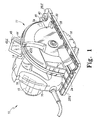
- the power tool assembly 10 includes a power tool 11 which in this embodiment is a power saw.
- the power tool 11 includes a housing 14 and an electric motor 15 (shown in phantom) positioned within the housing 14.
- the motor is connectable to a power source and is operable to rotatably drive a working element 18 to perform work on a workpiece.
- the power tool 11 is a circular saw and the working element 18 is a circular saw blade.
- the teachings of the present disclosure may apply to other power tools.
- the power tool may be a router and the working element may be a router bit.
- a handle 20 and a blade guard 24 are attached to the housing 14.
- the blade guard surrounds an upper portion of the saw blade 18.
- An on/off switch 19 (shown in phantom) is supported on the main handle 20 and selectively connects the motor 15 to the power source thereby enabling selective rotation of the saw blade 18.
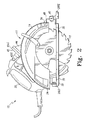
- the circular saw 11 also includes a base 28 attached to the housing 14.
- the base 28 serves for guiding the hand circular saw on the surface of a workpiece to be sawed.
- a portion of the saw blade 18 extends through an opening 30 defined in the base 28.
- the base 28 includes a leading edge 28LE and a trailing edge 28TE.
- the opening 30 is interposed between the leading edge 28LE and the trailing edge 28TE.
- the leading edge 28LE of the base 28 is positioned in front of (or leads) the trailing edge 28LE of the base 28 during a cutting operation.
- the circular saw 11 includes a front pivot depth adjustment mechanism 34 (shown in phantom) operable to adjust the depth of cut of the saw blade 18.
- the circular saw 10 may include, for example, a rear depth adjustment mechanism or a drop shoe depth adjustment mechanism rather than the front pivot depth adjustment mechanism 34.
- the present disclosure may apply to a circular saw with any type of depth adjustment mechanism or with no depth adjustment mechanism.
- the circular saw 11 may operate using a commercial power supply, such as an alternating current (AC) of, e.g., 110 volts, 120 volts or 220 volts.
- AC alternating current
- the circular saw may be "cordless” and may operate using a rechargeable battery, such as a nickel-cadmium or nickel metal-hydride battery.
- the present teachings may be advantageously utilized with both types of power tool designs, corded or cordless.
- the power tool assembly 10 further includes an imaging device 40 positioned on or otherwise supported by the power tool 11 to capture images of the work area, or the interface area at which the working element of the tool and the workpiece come into contact with each other.
- the power tool assembly 10 further includes a display device 44.
- the captured images of the interface area are output or otherwise transmitted to the display device 44 for viewing by the tool operator.
- the imaging device 40 is configured to generate data signals representative of a detected image.
- the display device 44 is configured to receive the data signals generated by the imaging device 40 and generated a visible representation of the detected image.
- the detected image is an image of the interface area at which the working element of the tool and the workpiece come into contact with each other.
- An exemplary imaging device 40 may include a camera with video recording or video streaming functionality.
- the video camera comprises a CCD (charge coupled device) camera although any suitable type of video camera may be used.
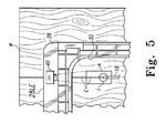
- the CCD camera 40 is mounted to the circular saw 11 so as to be positioned to capture images of the working element of the tool in contact with the workpiece as shown by the phantom lines in FIGS. 4 and 5 .
- the CCD camera 40 is mounted to the base 28 by fasteners (not shown).
- the CCD camera 40 is mounted to the base by an adhesive (not shown).
- FIG. 5 shows an exemplary image area A of the camera 40.
- the image area A preferably includes at least the interface area between the working element 18 and the workpiece W as well as a portion of the workpiece in front of the interface area.
- a portion of a cut line C may be included in the image to aid a tool operator in maintaining the working element 18 in alignment with the cut line C during a cutting operation.
- the CCD camera 40 may be elevated slightly with respect to the base 28 so that the camera may be tilted at a downward angle in relation to a horizontal plane defined by the base 28.
- the downward tilt of the camera allows the camera to capture images of the interface area A at the point of contact between the saw blade 18 and a workpiece W, as well as the area of the workpiece directly in front of the contact point as shown in FIGS. 4 and 5 .
- the CCD camera 40 may be mounted to the base in any suitable manner. In one embodiment, the CCD camera is fixedly mounted to the base by fasteners (not shown). In this embodiment, the alignment and orientation of the imaging device 40 may be provided during manufacturing of the power tool assembly 10.
- the CCD camera may be provided with a position adjustment mechanism (not shown) that allows a tool operator to selectively adjust the position of the camera 40 with respect to the base 28.
- the position adjustment mechanism would allow the imaging device 40 to be adjusted in relation to the base 28 in any of the following directions and/or orientations: laterally (i.e. from the left lateral side of the base 28 to the right lateral side, and vice versa), axially (i.e. away from the point of contact of the blade and the workpiece, and vice versa), and rotationally (i.e. at any of a plurality of angles of tilt of the camera 40 with respect to the plane defined by the base 28, for example, one angle of tilt being shown in FIG. 4 ).
- Video data representative of detected images of the interface area A in the form of video signals are provided or otherwise transmitted to the display device 44 via a signal wire 48 which may be routed from the imaging device 40 through the housing 14 to the display device 44.
- the imaging device 40 may be configured to wirelessly transmit the video data to the display device 44.
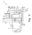
- the display device 44 includes a display screen 45 which is configured to display images representative of the detected images thereon for viewing by the tool operator.
- the display screen 45 includes a leading edge 45LE and a trailing edge 45TE.
- the display device 44 is preferably configured as a liquid crystal display device, although other types of display devices may be used.
- the display device 44 may be a color or a black and white display device. In the embodiment of FIGS.
- the display screen 45 is approximately 2"x2", although any suitably sized display screen may be used.
- a relatively small display screen such as one sized to be 2"x2" provides for adequate viewing of the working area by the operator while not being bulky or visually obstructive to a user.
- the imaging device 40 and/or the display device 44 includes the necessary data format conversion circuitry as is well know in the art.
- the display device 44 is positioned on or otherwise supported by an upper portion of the housing 14 and oriented to display images toward the rear of the power tool 11 as shown in FIGS. 1-3 .
- This positioning allows the operative part of the display screen 45 to remain in the field of view of a tool operator while the operator is in a natural work position.
- the display screen 45 is angled or otherwise tilted relative to horizontal with the top edge of the display screen 45 being positioned vertically higher than the bottom edge of the display screen 45.
- the exact angle or tilt of the display screen 45 depends on the configuration of the tool assembly, and the preference of the operator.
- the angle of the display screen 45 may selected to be vertical or horizontal or any angle therebetween.
- the display device 44 may be mounted to the saw housing in any suitable manner such as with fasteners (not shown) or an adhesive (not shown). In one embodiment (not shown), the display device 44 may be partially mounted within the housing 14 so that only the viewing portion of the display screen 45 is visible to the operator. Therefore, the housing can protect the display device 44 from damage that may occur from dropping the tool assembly 10. Moreover, the display device 44 may be fixedly mounted to the housing 14, or alternatively, the display device 44 may be attached to the housing in a manner that allows adjustment of the orientation of the display device 44 relative to horizontal. For instance, the display device may be attached to the housing by a hinge mechanism (not shown) that allows pivotal movement of the display device 44 relative to the housing 14.
- the display device may be attached to the housing via an adjustment mechanism (not shown) that allows the display device 44 to rotationally move about a vertical axis as well as pivotably move about a horizontal axis.
- an adjustment mechanism (not shown) that allows the display device 44 to rotationally move about a vertical axis as well as pivotably move about a horizontal axis.
- Such adjustment mechanism would allow the screen to be temporarily fixed in relation to the housing at any of these rotational and pivotal positions.
- the imaging device 40 and display device 44 may have their own power source, such as a battery.
- the imaging device 40 and display device 44 may be configured so that they are activated when the power to the circular saw is turned on.
- the imaging device 40 and display device 44 may be provided with a separate power switch (not shown) to turn the imaging device and display device on and off independently from the power tool 11. This allows a user to investigate the location of a cut to be made on a workpiece without the need to turn on the power to the power tool 11.
- the imaging device is positioned to capture images of the point of contact between the working element of the tool 11 and the workpiece (i.e. the working area) as well as the area of the workpiece immediately in front of the point of contact.
- the video data is provided to the display device 44 which is attached to the upper portion of the saw housing where representative images of the work area may be viewed by the tool operator.
- the positioning and orientation of the display device is such that the tool operator may maintain a natural work position while viewing the display screen, and hence, the work area of the tool. Therefore, alignment of the working element of the tool with a cut line marked on the workpiece is facilitated during a cutting operation thereby enabling highly accurate and precise cuts in the workpiece.
Landscapes
- Engineering & Computer Science (AREA)
- Mechanical Engineering (AREA)
- Sawing (AREA)
Applications Claiming Priority (1)
| Application Number | Priority Date | Filing Date | Title |
|---|---|---|---|
| US11/810,928 US20080302226A1 (en) | 2007-06-07 | 2007-06-07 | Power tool having imaging device and display device |
Publications (1)
| Publication Number | Publication Date |
|---|---|
| EP2000243A2 true EP2000243A2 (fr) | 2008-12-10 |
Family
ID=39731718
Family Applications (1)
| Application Number | Title | Priority Date | Filing Date |
|---|---|---|---|
| EP20080157246 Withdrawn EP2000243A2 (fr) | 2007-06-07 | 2008-05-30 | Outil électrique doté d'un dispositif d'imagerie et d'un dispositif d'affichage |
Country Status (3)
| Country | Link |
|---|---|
| US (1) | US20080302226A1 (fr) |
| EP (1) | EP2000243A2 (fr) |
| CN (1) | CN101323108A (fr) |
Cited By (4)
| Publication number | Priority date | Publication date | Assignee | Title |
|---|---|---|---|---|
| WO2009138271A1 (fr) * | 2008-05-14 | 2009-11-19 | Robert Bosch Gmbh | Machine-outil, en particulier machine-outil portative |
| WO2011163277A3 (fr) * | 2010-06-21 | 2012-05-03 | William Alexander Barr | Dispositif de localisation pour une utilisation avec des outils électriques |
| CN106270762A (zh) * | 2016-10-22 | 2017-01-04 | 郑运长 | 一种智能钢板切割机器人 |
| WO2021135876A1 (fr) * | 2019-12-31 | 2021-07-08 | 南京德朔实业有限公司 | Scie circulaire électrique |
Families Citing this family (21)
| Publication number | Priority date | Publication date | Assignee | Title |
|---|---|---|---|---|
| US8560047B2 (en) | 2006-06-16 | 2013-10-15 | Board Of Regents Of The University Of Nebraska | Method and apparatus for computer aided surgery |
| DE102006052808A1 (de) * | 2006-11-09 | 2008-05-15 | Robert Bosch Gmbh | Handhubsägemaschine |
| US20080229589A1 (en) * | 2007-03-23 | 2008-09-25 | Danny Bone | Power tool having improved visibility of the cutting area |
| DE102008001809A1 (de) * | 2008-05-15 | 2009-11-19 | Robert Bosch Gmbh | Arbeitsverfahren für eine Werkzeugmaschine, insbesondere eine handgehaltene Werkzeugmaschine |
| DE102008040071A1 (de) * | 2008-07-02 | 2010-01-07 | Robert Bosch Gmbh | Werkzeugmaschine, insbesondere handgehaltene Werkzeugmaschine |
| DE102008055059A1 (de) * | 2008-12-22 | 2010-06-24 | Robert Bosch Gmbh | Werkzeugmaschine, insbesondere Handwerkzeugmaschine |
| DE102009054709A1 (de) * | 2009-12-16 | 2011-06-22 | Robert Bosch GmbH, 70469 | Werkzeugmaschine, insbesondere handgehaltene Werkzeugmaschine |
| WO2012159123A2 (fr) * | 2011-05-19 | 2012-11-22 | Alec Rivers | Outils à guidage automatique |
| US11911117B2 (en) | 2011-06-27 | 2024-02-27 | Board Of Regents Of The University Of Nebraska | On-board tool tracking system and methods of computer assisted surgery |
| AU2012319093A1 (en) | 2011-06-27 | 2014-01-16 | Board Of Regents Of The University Of Nebraska | On-board tool tracking system and methods of computer assisted surgery |
| US9498231B2 (en) | 2011-06-27 | 2016-11-22 | Board Of Regents Of The University Of Nebraska | On-board tool tracking system and methods of computer assisted surgery |
| EP2852868B1 (fr) | 2012-04-26 | 2021-12-01 | Shaper Tools, Inc. | Systèmes et procédés permettant de réaliser une tâche sur un matériau, ou permettant de localiser la position d'un dispositif par rapport à la surface du matériau |
| US20140005807A1 (en) * | 2012-06-29 | 2014-01-02 | Black & Decker Inc. | System for Enhancing Operation of Power Tools |
| US10105149B2 (en) | 2013-03-15 | 2018-10-23 | Board Of Regents Of The University Of Nebraska | On-board tool tracking system and methods of computer assisted surgery |
| WO2016183390A1 (fr) | 2015-05-13 | 2016-11-17 | Taktia Llc | Systèmes, procédés et appareil pour outils guidés |
| DE102016210770A1 (de) * | 2016-06-16 | 2017-12-21 | Robert Bosch Gmbh | Verfahren zu einer Unterstützung eines Bedieners einer tragbaren Werkzeugmaschine |
| RU2748005C2 (ru) | 2016-08-19 | 2021-05-18 | Шапер Тулс, Инк. | Системы, способы и устройство для совместного использования данных об изготовлении инструмента и конструктивных данных |
| CN106735546A (zh) * | 2016-12-23 | 2017-05-31 | 常州格力博有限公司 | 一种切割工具 |
| US10875109B1 (en) | 2018-04-30 | 2020-12-29 | Kreg Enterprises, Inc. | Adaptive cutting system |
| US11858106B2 (en) * | 2019-08-08 | 2024-01-02 | Black & Decker Inc. | Power tools and power tools platform |
| US12544079B2 (en) | 2021-01-20 | 2026-02-10 | Mako Surgical Corp. | Robotic hand-held surgical instrument systems and methods |
Family Cites Families (18)
| Publication number | Priority date | Publication date | Assignee | Title |
|---|---|---|---|---|
| US3504716A (en) * | 1966-12-28 | 1970-04-07 | Stanley Works | Power tool and guide therefor |
| FI64760C (fi) * | 1981-05-29 | 1984-01-10 | Ahlstroem Oy | Foerfarande foer inriktning av en stock |
| US4667113A (en) * | 1985-08-09 | 1987-05-19 | Hitachi Seiko Ltd. | Tool failure detection apparatus |
| AT393986B (de) * | 1989-06-26 | 1992-01-10 | Payr Hans | Vorrichtung zum zerteilen von werkstuecken, insbesondere von holz |
| FR2651428A1 (fr) * | 1989-09-06 | 1991-03-08 | Bleicher Paul | Outil de dentisterie, notamment contre-angle de fraisage a controle-visuel. |
| US5038481A (en) * | 1990-05-04 | 1991-08-13 | Lonnie Smith | Saber saw tracking light |
| US5375495A (en) * | 1992-05-18 | 1994-12-27 | Porter-Cable Corporation | Optical alignment system for circular power saws |
| US6219585B1 (en) * | 1994-07-21 | 2001-04-17 | Silvatech Corporation | Three dimensional log scanning device for a log positioning and saw system |
| US6221007B1 (en) * | 1996-05-03 | 2001-04-24 | Philip S. Green | System and method for endoscopic imaging and endosurgery |
| US5928137A (en) * | 1996-05-03 | 1999-07-27 | Green; Philip S. | System and method for endoscopic imaging and endosurgery |
| US6055734A (en) * | 1999-03-04 | 2000-05-02 | Ryobi North America, Inc. | Circular saw with blade viewing window |
| WO2001007868A1 (fr) * | 1999-07-27 | 2001-02-01 | California Cedar Products Company | Systeme et procede automatiques d'inspection des dents d'une scie circulaire |
| DE10018255C2 (de) * | 2000-04-13 | 2003-08-28 | Leica Microsystems | Laserschneid-Verfahren und Laserschneid-Vorrichtung zum Laserschneiden mit mikroskopischer Proben |
| AU2002248470A1 (en) * | 2001-02-22 | 2002-09-12 | Toolz, Ltd. | Tools with orientation detection |
| US6474378B1 (en) * | 2001-05-07 | 2002-11-05 | S-B Power Tool Company | Plunge router having electronic depth adjustment |
| US6584695B1 (en) * | 2002-01-02 | 2003-07-01 | Chin-Chin Chang | Laser alignment device of a circular saw |
| US20060037445A1 (en) * | 2004-08-18 | 2006-02-23 | Sergyeyenko Oleksiy P | Circular saw with laser and protractor |
| US20080229589A1 (en) * | 2007-03-23 | 2008-09-25 | Danny Bone | Power tool having improved visibility of the cutting area |
-
2007
- 2007-06-07 US US11/810,928 patent/US20080302226A1/en not_active Abandoned
-
2008
- 2008-05-30 EP EP20080157246 patent/EP2000243A2/fr not_active Withdrawn
- 2008-06-06 CN CNA2008101446137A patent/CN101323108A/zh active Pending
Cited By (6)
| Publication number | Priority date | Publication date | Assignee | Title |
|---|---|---|---|---|
| WO2009138271A1 (fr) * | 2008-05-14 | 2009-11-19 | Robert Bosch Gmbh | Machine-outil, en particulier machine-outil portative |
| US9073134B2 (en) | 2008-05-14 | 2015-07-07 | Robert Bosch Gmbh | Power tool, particularly a hand-held power tool |
| WO2011163277A3 (fr) * | 2010-06-21 | 2012-05-03 | William Alexander Barr | Dispositif de localisation pour une utilisation avec des outils électriques |
| CN106270762A (zh) * | 2016-10-22 | 2017-01-04 | 郑运长 | 一种智能钢板切割机器人 |
| WO2021135876A1 (fr) * | 2019-12-31 | 2021-07-08 | 南京德朔实业有限公司 | Scie circulaire électrique |
| US12145205B2 (en) | 2019-12-31 | 2024-11-19 | Nanjing Chervon Industry Co., Ltd. | Electric circular saw |
Also Published As
| Publication number | Publication date |
|---|---|
| US20080302226A1 (en) | 2008-12-11 |
| CN101323108A (zh) | 2008-12-17 |
Similar Documents
| Publication | Publication Date | Title |
|---|---|---|
| EP2000243A2 (fr) | Outil électrique doté d'un dispositif d'imagerie et d'un dispositif d'affichage | |
| US11639009B2 (en) | Portable cutting devices | |
| US8826548B2 (en) | Hand-held jigsaw | |
| US10078320B2 (en) | Automatically guided tools | |
| US20080229589A1 (en) | Power tool having improved visibility of the cutting area | |
| US20080252726A1 (en) | Video aid system | |
| US20110251727A1 (en) | Motor-driven working device | |
| US20130019735A1 (en) | Machine Tool, Especially Hand-Held Machine Tool | |
| WO2009047629A1 (fr) | Moyens d'affichage visuel pour un outil électrique | |
| US20100032178A1 (en) | Procedure for operating a machine tool and machine tool for this purpose | |
| CN102105275A (zh) | 手持工具机 | |
| US12070871B2 (en) | Hand-held power tool having a bearing arrangement | |
| JP2010115794A (ja) | 切断機 | |
| CN1899762A (zh) | 安装在手持式切割装置的固定部件上的激光发生器 | |
| EP1707328B1 (fr) | Outil portatif de découpe | |
| US11226608B2 (en) | Method for machining a workpiece | |
| EP3067137B1 (fr) | Outil de découpe | |
| US20040168327A1 (en) | Cutting tool | |
| JP2011520628A (ja) | 工作機械、特に手持ち式の工作機械 | |
| US20110308369A1 (en) | Machine Tool, Particularly a Hand-Held Power Tool | |
| JP4864420B2 (ja) | 電動切削工具 | |
| JP5240671B2 (ja) | 切断工具 | |
| JP2010214536A (ja) | 切断工具 | |
| KR101795519B1 (ko) | 가이드 레이저 장치를 구비한 휴대용 컷소 | |
| JP2003089013A (ja) | 携帯用電気丸鋸 |
Legal Events
| Date | Code | Title | Description |
|---|---|---|---|
| PUAI | Public reference made under article 153(3) epc to a published international application that has entered the european phase |
Free format text: ORIGINAL CODE: 0009012 |
|
| AK | Designated contracting states |
Kind code of ref document: A2 Designated state(s): AT BE BG CH CY CZ DE DK EE ES FI FR GB GR HR HU IE IS IT LI LT LU LV MC MT NL NO PL PT RO SE SI SK TR |
|
| AX | Request for extension of the european patent |
Extension state: AL BA MK RS |
|
| STAA | Information on the status of an ep patent application or granted ep patent |
Free format text: STATUS: THE APPLICATION IS DEEMED TO BE WITHDRAWN |
|
| 18D | Application deemed to be withdrawn |
Effective date: 20101201 |