EP1998597B1 - Heizvorrichtung - Google Patents
Heizvorrichtung Download PDFInfo
- Publication number
- EP1998597B1 EP1998597B1 EP08103027A EP08103027A EP1998597B1 EP 1998597 B1 EP1998597 B1 EP 1998597B1 EP 08103027 A EP08103027 A EP 08103027A EP 08103027 A EP08103027 A EP 08103027A EP 1998597 B1 EP1998597 B1 EP 1998597B1
- Authority
- EP
- European Patent Office
- Prior art keywords
- heating device
- sleeve
- phase
- change material
- enclosure
- Prior art date
- Legal status (The legal status is an assumption and is not a legal conclusion. Google has not performed a legal analysis and makes no representation as to the accuracy of the status listed.)
- Not-in-force
Links
- 238000010438 heat treatment Methods 0.000 title claims description 62
- 239000012782 phase change material Substances 0.000 claims description 24
- 230000002441 reversible effect Effects 0.000 claims description 2
- 239000010410 layer Substances 0.000 description 5
- 239000011241 protective layer Substances 0.000 description 5
- 239000000463 material Substances 0.000 description 4
- 238000005452 bending Methods 0.000 description 3
- OKTJSMMVPCPJKN-UHFFFAOYSA-N Carbon Chemical compound [C] OKTJSMMVPCPJKN-UHFFFAOYSA-N 0.000 description 1
- 229910052799 carbon Inorganic materials 0.000 description 1
- 230000005484 gravity Effects 0.000 description 1
- 230000002459 sustained effect Effects 0.000 description 1
- XLYOFNOQVPJJNP-UHFFFAOYSA-N water Substances O XLYOFNOQVPJJNP-UHFFFAOYSA-N 0.000 description 1
Images



Classifications
-
- H—ELECTRICITY
- H05—ELECTRIC TECHNIQUES NOT OTHERWISE PROVIDED FOR
- H05B—ELECTRIC HEATING; ELECTRIC LIGHT SOURCES NOT OTHERWISE PROVIDED FOR; CIRCUIT ARRANGEMENTS FOR ELECTRIC LIGHT SOURCES, IN GENERAL
- H05B3/00—Ohmic-resistance heating
- H05B3/40—Heating elements having the shape of rods or tubes
Definitions
- This application claims priority of Chinese Application No. 200710108149.1, filed on May 30, 2007 .
- This invention relates to a heating device, and more particularly, to a heating device including a phase-change material and that can be arranged by bending thereof so as to optimize heat-release distribution.
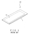
- a conventional heating device 100 commonly referred to as a "hand warmer, " comprises a pocket 7 that is filled with a phase-change material 70.
- the user Before the user can use the hand warmer 100, the user must pre-heat the hand warmer 100 using an external device or means, such as by putting the hand warmer 100 in hot water or by using a microwave oven, so that the phase-change material 70 is heated. As a result, the phase-change material 70 undergoes phase change and therefore, is able to better store heat.
- the conventional hand warmer 100 can be used only in an indoor setting where such external devices and means are readily available. Further, heat generated from the conventional hand warmer 100 cannot be sustained for a long time since the phase-change material 70 quickly loses its heat energy and returns to its initial state.
- the invention corresponds to a heating device according to claim 1.
- a heating device 1 includes an electrically conductive heating wire unit 3 that has two opposite end portions 10, 11 and a middle portion 12 extending between the end portions 10, 11, a phase-change material 6 that encloses the middle portion 12 of the heating wire unit 3 and that is capable of storing heat through phase changing, and an enclosure 4 that encloses the phase-change material 6 for preventing leakage of the phase-change material 6.
- the heating wire unit 3 is an electrothermal wire, which can be a metal- or carbon fiber-type electrothermal wire.
- the enclosure 4 includes a sleeve 41 and a pair of end caps 2.
- the phase-change material 6 fills the sleeve 41.
- the end caps 2 cap two ends of the sleeve 41 and are formed with holes 20 for extension of the end portions 10, 11 of the heating wire unit 3 therethrough, respectively.
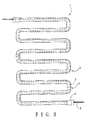
- the sleeve 41 of the enclosure 4 is made of a flexible material that allows for reversible reshaping of the sleeve 41. As such, the sleeve 41 is bendable to place the heating device 1 in any arrangement to suit the particular needs of a user. As an example, with reference to Fig. 3 , the heating device 1 is arranged in a meandering configuration to cover a relatively large area.
- a wire support 5 is disposed in the sleeve 41.
- the wire support 5 includes a C-shaped ring 50 for holding the heating wire unit 3 therein, and a plurality of protrusions 52 projecting outwardly from the C-shaped ring 50 and that are angularly displaced.
- a plurality of the wire supports 5 may be disposed in the sleeve 41 to provide full support to the heating wire unit 3.
- a temperature controller 15 and a temperature sensor 14 are separately mounted on the enclosure 4 of the heating device 1. Operations of the temperature controller 15 and the temperature sensor 14 will be described below.
- the end caps 2 are fabricated from the same flexible material as the enclosure 4. Further, the hole 20 in one of the end caps 2 is aligned with the hole 20 in the other of the end caps 2 so as to allow the heating wire unit 3 to extend approximately in a straight line through the sleeve 41 (prior to any bending thereof).
- the holes 20 are packed with a waterproof material to prevent leakage of the phase-change material 6.
- the heating wire unit 3 may shift downward to thereby contact the inner wall of the sleeve 41 by virtue of gravity acting thereupon. As a result, heat is not uniformly distributed within the enclosure 4.
- the wire support 5 mounted inside the sleeve 41 prevents the heating wire unit 3 from contacting the inner wall of the sleeve 41.
- the heating wire unit 3 is more fully supported to better prevent the same from contacting the inner wall of the sleeve 41.
- phase-change material 6 absorbs the heat and therefore, undergoes a change in phase so as to better store the heat. This stored heat is then released from the phase-change material 6. Because of the use of the phase-change material 6 in the heating device 1, only a small amount of the electrical power is required by the heating device 1.
- the phase-change material 6 may be omitted from the configuration of the heating device 1.
- the heating device 1 is still operable to generate, store, and emit heat, albeit in a manner less efficiently than when the phase-change material 6 is filled in the enclosure 4.
- the temperature sensor 14 is mounted on the enclosure 4 as described above, and is used to monitor the temperature of the heating device 1. Further, as shown in Figure 5 , the temperature controller 15 is mounted on the enclosure 4 and is coupled to the temperature sensor 14. The temperature controller 15 operates in conjunction with the temperature sensor 14 to control the temperature of the heating device 1. Once the temperature of the heating device 1 reaches a predetermined level, the temperature controller 15 will control the supply of the electrical power to the heating wire unit 3 such that the predetermined temperature level is maintained.
- FIG. 7 illustrates a modified example of the first preferred embodiment of the heating device 1 according to the present invention.
- each of the end caps 2 is further formed with a second hole 21 through which the phase-change material 6 may be filled into the enclosure 4. After the phase-change material 6 fills the enclosure 4, the hole 21 is packed with waterproof material.
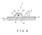
- Figure 8 illustrates the second preferred embodiment of the heating device 1' of the present invention.
- the enclosure 4' includes a corrugated layer 17 having a planar portion 171 and a protruding portion 172 protruding from the planar portion 171.
- the protruding portion 172 defines a groove 50 that has an open end 51.
- the enclosure 4' further includes a planar layer 16 that is attached to the corrugated layer 17 so as to cover the open end 51 of the groove 50.
- the phase-change material 6' fills the groove 50.
- a protective layer 18 is attached to the planar layer 16, and the temperature sensor 14' and the temperature controller 15' are sandwiched between the protective layer 18 and the planar layer 16.
- the heating device 1' can be provided on a piece of clothing (not shown) of the user, such as a jacket.
- the protective layer 18 is exposed to the environment, while the heating wire unit 3' is proximate to the user's body. Because of this arrangement, the protective layer 18 can insulate the heating device 1' from the cold environment while the heating wire unit 3' generates heat towards the user's body.
- the temperature sensor 14' and the temperature controller 15' of the second preferred embodiment may operate in combination to control the temperature setting of the heating device 1'.
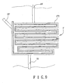
- FIG. 9 illustrates an exemplary layout of the heating device 1' in accordance with the second preferred embodiment.
- This exemplary layout of the heating device 1' is realized by forming the groove 50 in a meandering shape.
- the phase-change material 6' is supplied to fill the groove 50 through an inlet tube 19, and at least one outlet tube 19' may be provided on the heating device 1' so as to discharge air bubbles.
- the heating device 1' will nevertheless remain operable.
Landscapes
- Resistance Heating (AREA)
- Thermotherapy And Cooling Therapy Devices (AREA)
Claims (4)
- Heizgerät (1), gekennzeichnet durch:- eine elektrisch leitfähige Heizdrahteinheit (3) mit zwei gegenüberliegenden Endabschnitten (10, 11) und einem Mittelabschnitt (12), der zwischen den Endabschnitten (10, 11) verläuft;- einen Phasenwandelmaterial (6, 6'), das den Mittelabschnitt (12) der Heizdrahteinheit (3) umschließt und imstande ist, Wärme durch Phasenumwandlung zu speichern; und- eine Einfassung (4), die das Phasenwandelmaterial (6, 6') zum Verhindern von Entweichen des Phasenwandelmaterials (6, 6') umschließt, wobei die Einfassung (4) eine Hülse (41) und ein Paar Endkappen (2) enthält, wobei das Phasenwandelmaterial (6, 6') die Hülse (41) füllt, wobei die Endkappen (2) zwei Enden der Hülse (41) abdecken und mit Löchern (20) zur Erweiterung der Endabschnitte (10, 11) der Heizdrahteinheit (3) jeweils dort hindurch ausgebildet sind; gekennzeichnet durch- eine Drahthalterung (5), die in der Hülse (41) angeordnet ist und einen C-förmigen Ring (50) zum Halten der Heizdrahteinheit (3) darin und mehrere Vorsprünge (52) enthält, welche von dem C-förmigen Ring (50) nach außen vorstehen und winklig versetzt sind.
- Heizgerät (1) nach Anspruch 1, dadurch gekennzeichnet, dass die Hülse (41) biegsam ist, um reversibles Umformen der Hülse (41) zu ermöglichen.
- Heizgerät (1) nach Anspruch 1, ferner gekennzeichnet durch einen Temperaturregler (15, 15') und einen Temperaturfühler (14, 14'), die jeder an der Einfassung (4) des Heizgeräts (1) angebracht sind.
- Heizgerät (1) nach Anspruch 1, gekennzeichnet durch mehrere der Drahthalterungen (5), die in der Hülse (41) angeordnet sind.
Applications Claiming Priority (1)
| Application Number | Priority Date | Filing Date | Title |
|---|---|---|---|
| CN200710108149 | 2007-05-30 |
Publications (3)
| Publication Number | Publication Date |
|---|---|
| EP1998597A2 EP1998597A2 (de) | 2008-12-03 |
| EP1998597A3 EP1998597A3 (de) | 2009-03-04 |
| EP1998597B1 true EP1998597B1 (de) | 2013-02-13 |
Family
ID=39859725
Family Applications (1)
| Application Number | Title | Priority Date | Filing Date |
|---|---|---|---|
| EP08103027A Not-in-force EP1998597B1 (de) | 2007-05-30 | 2008-03-27 | Heizvorrichtung |
Country Status (4)
| Country | Link |
|---|---|
| US (2) | US20080296287A1 (de) |
| EP (1) | EP1998597B1 (de) |
| JP (1) | JP2008296019A (de) |
| CN (1) | CN101315259B (de) |
Families Citing this family (3)
| Publication number | Priority date | Publication date | Assignee | Title |
|---|---|---|---|---|
| CN103453572A (zh) * | 2013-08-23 | 2013-12-18 | 济南喜莱盈家俱制造有限公司 | 一种碳纤维水暖装置 |
| US9829947B1 (en) | 2014-04-04 | 2017-11-28 | Google Llc | Selecting and serving a content item based on device state data of a device |
| CN115844177A (zh) * | 2022-12-29 | 2023-03-28 | 北京科技大学 | 一种便携式可充电自控温相变储热睡袋 |
Family Cites Families (33)
| Publication number | Priority date | Publication date | Assignee | Title |
|---|---|---|---|---|
| US2529215A (en) * | 1947-11-10 | 1950-11-07 | Trane Co | Heat exchanger |
| US2915615A (en) * | 1957-09-09 | 1959-12-01 | Welcraft Products Co Inc | Electric heating unit with control thermostat |
| US3286078A (en) * | 1964-04-06 | 1966-11-15 | Hynes Electric Heating Company | Flexible internal heater |
| US3751620A (en) * | 1970-03-10 | 1973-08-07 | Yuasa Battery Co Ltd | Electric garment |
| GB1514789A (en) * | 1975-12-16 | 1978-06-21 | Liquifry Co Ltd | Electrical heater |
| US4543474A (en) * | 1979-09-24 | 1985-09-24 | Raychem Corporation | Layered self-regulating heating article |
| US4424422A (en) * | 1980-08-04 | 1984-01-03 | Technar, Inc. | Thermostatically controlled electric diesel fuel heater |
| JPS6012086U (ja) * | 1983-07-04 | 1985-01-26 | 松下電器産業株式会社 | 蓄熱体 |
| IT1177220B (it) * | 1983-12-03 | 1987-08-26 | Hotset Heizpatronen Zubehoer | Elemento riscaldante elettrico a cartuccia |
| FR2602959B1 (fr) * | 1986-08-19 | 1989-05-05 | Salomon Sa | Dispositif de chauffage loge dans un article vestimentaire ou une chaussure, notamment une chaussure de ski |
| US4743726A (en) * | 1986-10-14 | 1988-05-10 | Hughes Thomas E | Microwave activated heating element |
| JPH0215123U (de) * | 1988-07-15 | 1990-01-30 | ||
| US5300105A (en) * | 1990-02-26 | 1994-04-05 | Vesture Corporation | Therapeutic pad and method |
| US5245161A (en) * | 1990-08-31 | 1993-09-14 | Tokyo Kogyo Boyeki Shokai, Ltd. | Electric heater |
| US6004662A (en) * | 1992-07-14 | 1999-12-21 | Buckley; Theresa M. | Flexible composite material with phase change thermal storage |
| US5220954A (en) * | 1992-10-07 | 1993-06-22 | Shape, Inc. | Phase change heat exchanger |
| US5302806A (en) * | 1992-12-08 | 1994-04-12 | Thermo-Cool Products Inc. | Heated vest with pouches for accommodating inserted heating packets |
| JPH0675435U (ja) * | 1993-04-09 | 1994-10-25 | 東亜技研株式会社 | 蓄熱マット |
| US5386701A (en) * | 1994-02-03 | 1995-02-07 | Cao; Yiding | Human body cooling suit with heat pipe transfer |
| US5932129A (en) * | 1995-02-27 | 1999-08-03 | Vesture Corporation | Thermal retention device |
| US5750962A (en) * | 1995-02-27 | 1998-05-12 | Vesture Corporation | Thermal retention device |
| WO2000024348A1 (en) * | 1998-10-23 | 2000-05-04 | Medstat Financial, Inc. D/B/A Thermo-Tec | Pad for warming a patient |
| US6548789B1 (en) * | 1999-04-22 | 2003-04-15 | Malden Mills Industries, Inc. | Electric resistance heating/warming fabric articles |
| US6852956B2 (en) * | 1999-04-22 | 2005-02-08 | Malden Mills Industries, Inc. | Fabric with heated circuit printed on intermediate film |
| EP1220054B1 (de) * | 2000-12-22 | 2004-08-04 | Samsung Electronics Co., Ltd. | Fixierrolleranordnung eines elektrophotographischen Bilderzeugungsgeräts mit Arbeitsflüssigkeit in der Heizwalze |
| US7372006B2 (en) * | 2001-02-15 | 2008-05-13 | Integral Technologies, Inc | Low cost heating devices manufactured from conductive loaded resin-based materials |
| US6664512B2 (en) * | 2001-09-11 | 2003-12-16 | Sunbeam Products, Inc. | Warming blanket with heat reflective strips |
| US6727469B1 (en) * | 2002-11-22 | 2004-04-27 | April F. Parker | Heated booty |
| KR100513271B1 (ko) * | 2003-01-11 | 2005-09-09 | 김형곤 | 다공질의 난연성 압축섬유를 이용한 난방파이프 |
| FR2855359B1 (fr) * | 2003-05-19 | 2005-07-01 | Seb Sa | Dispositif de chauffage d'un liquide pour appareil electromenager, appareil electromenager equipe d'un tel dispositif. |
| CN2645645Y (zh) * | 2003-06-27 | 2004-10-06 | 喻孟华 | 相位转换储热装置 |
| CN1290474C (zh) * | 2003-06-27 | 2006-12-20 | 喻孟华 | 相位转换储热装置的制造方法及其产品 |
| US7765811B2 (en) * | 2007-06-29 | 2010-08-03 | Laird Technologies, Inc. | Flexible assemblies with integrated thermoelectric modules suitable for use in extracting power from or dissipating heat from fluid conduits |
-
2007
- 2007-12-17 US US11/957,791 patent/US20080296287A1/en not_active Abandoned
-
2008
- 2008-03-27 EP EP08103027A patent/EP1998597B1/de not_active Not-in-force
- 2008-05-29 JP JP2008140804A patent/JP2008296019A/ja active Pending
- 2008-05-29 CN CN2008101087505A patent/CN101315259B/zh not_active Expired - Fee Related
- 2008-09-10 US US12/207,538 patent/US20090151904A1/en not_active Abandoned
Also Published As
| Publication number | Publication date |
|---|---|
| JP2008296019A (ja) | 2008-12-11 |
| EP1998597A2 (de) | 2008-12-03 |
| US20080296287A1 (en) | 2008-12-04 |
| CN101315259B (zh) | 2011-10-26 |
| CN101315259A (zh) | 2008-12-03 |
| EP1998597A3 (de) | 2009-03-04 |
| US20090151904A1 (en) | 2009-06-18 |
Similar Documents
| Publication | Publication Date | Title |
|---|---|---|
| US7286752B2 (en) | Device for heating a liquid for domestic appliance, domestic appliance fitted with said device | |
| BR112020002075B1 (pt) | Prensa térmica | |
| US7135036B2 (en) | Heating pad having a phase change material | |
| EP1998597A2 (de) | Heizvorrichtung | |
| KR200182019Y1 (ko) | 반도체소자를 이용한 온열치료기의 발열장치 | |
| BRPI0714745A2 (pt) | dispositivo de aquecimento elÉtrico para sistemas de canal quente | |
| GB2160965A (en) | Thermal storage device | |
| CN104224430A (zh) | 热疗设备的发热装置 | |
| ITPD940133A1 (it) | Riscaldatore elettronico ad immersione perfezionato | |
| EP3879200B1 (de) | Heizkörper mit temperaturbegrenzung | |
| EP3009057A1 (de) | Handtucherwärmungskonstruktion mit hoher wärmeeffizienz | |
| EP3562518B1 (de) | Vorrichtung zur verdampfung von flüchtigen substanzen mit docht und wärmereflektierendem element | |
| KR102219522B1 (ko) | 이중 석영관 히터 및 이를 포함하는 온수 가열용 석영관 히터 | |
| KR101888818B1 (ko) | 안전성이 향상된 찜질기 | |
| ES2546791T3 (es) | Dispositivo para conmutar varios dispositivos calentadores de un aparato de cocción así como aparato de cocción con tal dispositivo | |
| GB2442094A (en) | Heat pad with heat storage medium | |
| KR200369464Y1 (ko) | 휴대용 가열장치 | |
| JP2007061126A (ja) | 電気湯沸かし器 | |
| US6948419B2 (en) | Coffee maker | |
| KR100479506B1 (ko) | 전기 히터장치 | |
| CN209757371U (zh) | 一种具有调温功能的自行车折叠车把 | |
| JP2008232601A (ja) | 保温具 | |
| JP3173145U (ja) | 水槽用ヒーター装置 | |
| JP2007230631A (ja) | 温度管理装置 | |
| KR200372656Y1 (ko) | 냉,난방 침대패널장치 |
Legal Events
| Date | Code | Title | Description |
|---|---|---|---|
| PUAI | Public reference made under article 153(3) epc to a published international application that has entered the european phase |
Free format text: ORIGINAL CODE: 0009012 |
|
| AK | Designated contracting states |
Kind code of ref document: A2 Designated state(s): AT BE BG CH CY CZ DE DK EE ES FI FR GB GR HR HU IE IS IT LI LT LU LV MC MT NL NO PL PT RO SE SI SK TR |
|
| AX | Request for extension of the european patent |
Extension state: AL BA MK RS |
|
| PUAL | Search report despatched |
Free format text: ORIGINAL CODE: 0009013 |
|
| AK | Designated contracting states |
Kind code of ref document: A3 Designated state(s): AT BE BG CH CY CZ DE DK EE ES FI FR GB GR HR HU IE IS IT LI LT LU LV MC MT NL NO PL PT RO SE SI SK TR |
|
| AX | Request for extension of the european patent |
Extension state: AL BA MK RS |
|
| 17Q | First examination report despatched |
Effective date: 20090923 |
|
| 17P | Request for examination filed |
Effective date: 20090825 |
|
| AKX | Designation fees paid |
Designated state(s): AT BE BG CH CY CZ DE DK EE ES FI FR GB GR HR HU IE IS IT LI LT LU LV MC MT NL NO PL PT RO SE SI SK TR |
|
| GRAP | Despatch of communication of intention to grant a patent |
Free format text: ORIGINAL CODE: EPIDOSNIGR1 |
|
| GRAS | Grant fee paid |
Free format text: ORIGINAL CODE: EPIDOSNIGR3 |
|
| GRAA | (expected) grant |
Free format text: ORIGINAL CODE: 0009210 |
|
| AK | Designated contracting states |
Kind code of ref document: B1 Designated state(s): AT BE BG CH CY CZ DE DK EE ES FI FR GB GR HR HU IE IS IT LI LT LU LV MC MT NL NO PL PT RO SE SI SK TR |
|
| REG | Reference to a national code |
Ref country code: GB Ref legal event code: FG4D |
|
| REG | Reference to a national code |
Ref country code: AT Ref legal event code: REF Ref document number: 597072 Country of ref document: AT Kind code of ref document: T Effective date: 20130215 |
|
| REG | Reference to a national code |
Ref country code: IE Ref legal event code: FG4D |
|
| REG | Reference to a national code |
Ref country code: DE Ref legal event code: R096 Ref document number: 602008022052 Country of ref document: DE Effective date: 20130411 |
|
| PGFP | Annual fee paid to national office [announced via postgrant information from national office to epo] |
Ref country code: GB Payment date: 20130311 Year of fee payment: 6 Ref country code: FR Payment date: 20130409 Year of fee payment: 6 Ref country code: DE Payment date: 20130328 Year of fee payment: 6 |
|
| REG | Reference to a national code |
Ref country code: AT Ref legal event code: MK05 Ref document number: 597072 Country of ref document: AT Kind code of ref document: T Effective date: 20130213 |
|
| REG | Reference to a national code |
Ref country code: NL Ref legal event code: VDEP Effective date: 20130213 |
|
| REG | Reference to a national code |
Ref country code: LT Ref legal event code: MG4D |
|
| PG25 | Lapsed in a contracting state [announced via postgrant information from national office to epo] |
Ref country code: BG Free format text: LAPSE BECAUSE OF FAILURE TO SUBMIT A TRANSLATION OF THE DESCRIPTION OR TO PAY THE FEE WITHIN THE PRESCRIBED TIME-LIMIT Effective date: 20130513 Ref country code: ES Free format text: LAPSE BECAUSE OF FAILURE TO SUBMIT A TRANSLATION OF THE DESCRIPTION OR TO PAY THE FEE WITHIN THE PRESCRIBED TIME-LIMIT Effective date: 20130524 Ref country code: AT Free format text: LAPSE BECAUSE OF FAILURE TO SUBMIT A TRANSLATION OF THE DESCRIPTION OR TO PAY THE FEE WITHIN THE PRESCRIBED TIME-LIMIT Effective date: 20130213 Ref country code: LT Free format text: LAPSE BECAUSE OF FAILURE TO SUBMIT A TRANSLATION OF THE DESCRIPTION OR TO PAY THE FEE WITHIN THE PRESCRIBED TIME-LIMIT Effective date: 20130213 Ref country code: IS Free format text: LAPSE BECAUSE OF FAILURE TO SUBMIT A TRANSLATION OF THE DESCRIPTION OR TO PAY THE FEE WITHIN THE PRESCRIBED TIME-LIMIT Effective date: 20130613 Ref country code: NO Free format text: LAPSE BECAUSE OF FAILURE TO SUBMIT A TRANSLATION OF THE DESCRIPTION OR TO PAY THE FEE WITHIN THE PRESCRIBED TIME-LIMIT Effective date: 20130513 Ref country code: SE Free format text: LAPSE BECAUSE OF FAILURE TO SUBMIT A TRANSLATION OF THE DESCRIPTION OR TO PAY THE FEE WITHIN THE PRESCRIBED TIME-LIMIT Effective date: 20130213 |
|
| PG25 | Lapsed in a contracting state [announced via postgrant information from national office to epo] |
Ref country code: SI Free format text: LAPSE BECAUSE OF FAILURE TO SUBMIT A TRANSLATION OF THE DESCRIPTION OR TO PAY THE FEE WITHIN THE PRESCRIBED TIME-LIMIT Effective date: 20130213 Ref country code: GR Free format text: LAPSE BECAUSE OF FAILURE TO SUBMIT A TRANSLATION OF THE DESCRIPTION OR TO PAY THE FEE WITHIN THE PRESCRIBED TIME-LIMIT Effective date: 20130514 Ref country code: PL Free format text: LAPSE BECAUSE OF FAILURE TO SUBMIT A TRANSLATION OF THE DESCRIPTION OR TO PAY THE FEE WITHIN THE PRESCRIBED TIME-LIMIT Effective date: 20130213 Ref country code: LV Free format text: LAPSE BECAUSE OF FAILURE TO SUBMIT A TRANSLATION OF THE DESCRIPTION OR TO PAY THE FEE WITHIN THE PRESCRIBED TIME-LIMIT Effective date: 20130213 Ref country code: FI Free format text: LAPSE BECAUSE OF FAILURE TO SUBMIT A TRANSLATION OF THE DESCRIPTION OR TO PAY THE FEE WITHIN THE PRESCRIBED TIME-LIMIT Effective date: 20130213 Ref country code: PT Free format text: LAPSE BECAUSE OF FAILURE TO SUBMIT A TRANSLATION OF THE DESCRIPTION OR TO PAY THE FEE WITHIN THE PRESCRIBED TIME-LIMIT Effective date: 20130613 Ref country code: BE Free format text: LAPSE BECAUSE OF FAILURE TO SUBMIT A TRANSLATION OF THE DESCRIPTION OR TO PAY THE FEE WITHIN THE PRESCRIBED TIME-LIMIT Effective date: 20130213 |
|
| PG25 | Lapsed in a contracting state [announced via postgrant information from national office to epo] |
Ref country code: HR Free format text: LAPSE BECAUSE OF FAILURE TO SUBMIT A TRANSLATION OF THE DESCRIPTION OR TO PAY THE FEE WITHIN THE PRESCRIBED TIME-LIMIT Effective date: 20130213 |
|
| PG25 | Lapsed in a contracting state [announced via postgrant information from national office to epo] |
Ref country code: RO Free format text: LAPSE BECAUSE OF FAILURE TO SUBMIT A TRANSLATION OF THE DESCRIPTION OR TO PAY THE FEE WITHIN THE PRESCRIBED TIME-LIMIT Effective date: 20130213 Ref country code: MC Free format text: LAPSE BECAUSE OF NON-PAYMENT OF DUE FEES Effective date: 20130331 Ref country code: SK Free format text: LAPSE BECAUSE OF FAILURE TO SUBMIT A TRANSLATION OF THE DESCRIPTION OR TO PAY THE FEE WITHIN THE PRESCRIBED TIME-LIMIT Effective date: 20130213 Ref country code: DK Free format text: LAPSE BECAUSE OF FAILURE TO SUBMIT A TRANSLATION OF THE DESCRIPTION OR TO PAY THE FEE WITHIN THE PRESCRIBED TIME-LIMIT Effective date: 20130213 Ref country code: NL Free format text: LAPSE BECAUSE OF FAILURE TO SUBMIT A TRANSLATION OF THE DESCRIPTION OR TO PAY THE FEE WITHIN THE PRESCRIBED TIME-LIMIT Effective date: 20130213 Ref country code: CZ Free format text: LAPSE BECAUSE OF FAILURE TO SUBMIT A TRANSLATION OF THE DESCRIPTION OR TO PAY THE FEE WITHIN THE PRESCRIBED TIME-LIMIT Effective date: 20130213 Ref country code: EE Free format text: LAPSE BECAUSE OF FAILURE TO SUBMIT A TRANSLATION OF THE DESCRIPTION OR TO PAY THE FEE WITHIN THE PRESCRIBED TIME-LIMIT Effective date: 20130213 |
|
| REG | Reference to a national code |
Ref country code: CH Ref legal event code: PL |
|
| PLBE | No opposition filed within time limit |
Free format text: ORIGINAL CODE: 0009261 |
|
| STAA | Information on the status of an ep patent application or granted ep patent |
Free format text: STATUS: NO OPPOSITION FILED WITHIN TIME LIMIT |
|
| PG25 | Lapsed in a contracting state [announced via postgrant information from national office to epo] |
Ref country code: IT Free format text: LAPSE BECAUSE OF FAILURE TO SUBMIT A TRANSLATION OF THE DESCRIPTION OR TO PAY THE FEE WITHIN THE PRESCRIBED TIME-LIMIT Effective date: 20130213 |
|
| REG | Reference to a national code |
Ref country code: IE Ref legal event code: MM4A |
|
| 26N | No opposition filed |
Effective date: 20131114 |
|
| PG25 | Lapsed in a contracting state [announced via postgrant information from national office to epo] |
Ref country code: IE Free format text: LAPSE BECAUSE OF NON-PAYMENT OF DUE FEES Effective date: 20130327 Ref country code: CH Free format text: LAPSE BECAUSE OF NON-PAYMENT OF DUE FEES Effective date: 20130331 Ref country code: LI Free format text: LAPSE BECAUSE OF NON-PAYMENT OF DUE FEES Effective date: 20130331 |
|
| REG | Reference to a national code |
Ref country code: DE Ref legal event code: R097 Ref document number: 602008022052 Country of ref document: DE Effective date: 20131114 |
|
| PG25 | Lapsed in a contracting state [announced via postgrant information from national office to epo] |
Ref country code: MT Free format text: LAPSE BECAUSE OF FAILURE TO SUBMIT A TRANSLATION OF THE DESCRIPTION OR TO PAY THE FEE WITHIN THE PRESCRIBED TIME-LIMIT Effective date: 20130213 |
|
| REG | Reference to a national code |
Ref country code: DE Ref legal event code: R119 Ref document number: 602008022052 Country of ref document: DE |
|
| GBPC | Gb: european patent ceased through non-payment of renewal fee |
Effective date: 20140327 |
|
| REG | Reference to a national code |
Ref country code: FR Ref legal event code: ST Effective date: 20141128 |
|
| REG | Reference to a national code |
Ref country code: DE Ref legal event code: R119 Ref document number: 602008022052 Country of ref document: DE Effective date: 20141001 |
|
| PG25 | Lapsed in a contracting state [announced via postgrant information from national office to epo] |
Ref country code: FR Free format text: LAPSE BECAUSE OF NON-PAYMENT OF DUE FEES Effective date: 20140331 Ref country code: GB Free format text: LAPSE BECAUSE OF NON-PAYMENT OF DUE FEES Effective date: 20140327 Ref country code: DE Free format text: LAPSE BECAUSE OF NON-PAYMENT OF DUE FEES Effective date: 20141001 |
|
| PG25 | Lapsed in a contracting state [announced via postgrant information from national office to epo] |
Ref country code: TR Free format text: LAPSE BECAUSE OF FAILURE TO SUBMIT A TRANSLATION OF THE DESCRIPTION OR TO PAY THE FEE WITHIN THE PRESCRIBED TIME-LIMIT Effective date: 20130213 Ref country code: CY Free format text: LAPSE BECAUSE OF FAILURE TO SUBMIT A TRANSLATION OF THE DESCRIPTION OR TO PAY THE FEE WITHIN THE PRESCRIBED TIME-LIMIT Effective date: 20130213 |
|
| PG25 | Lapsed in a contracting state [announced via postgrant information from national office to epo] |
Ref country code: LU Free format text: LAPSE BECAUSE OF NON-PAYMENT OF DUE FEES Effective date: 20130327 Ref country code: HU Free format text: LAPSE BECAUSE OF FAILURE TO SUBMIT A TRANSLATION OF THE DESCRIPTION OR TO PAY THE FEE WITHIN THE PRESCRIBED TIME-LIMIT; INVALID AB INITIO Effective date: 20080327 |