EP1998397B1 - Fuel cell system and method of starting operation of fuel cell system - Google Patents
Fuel cell system and method of starting operation of fuel cell system Download PDFInfo
- Publication number
- EP1998397B1 EP1998397B1 EP08009411A EP08009411A EP1998397B1 EP 1998397 B1 EP1998397 B1 EP 1998397B1 EP 08009411 A EP08009411 A EP 08009411A EP 08009411 A EP08009411 A EP 08009411A EP 1998397 B1 EP1998397 B1 EP 1998397B1
- Authority
- EP
- European Patent Office
- Prior art keywords
- fuel cell
- energy storage
- power generation
- electrical energy
- cell system
- Prior art date
- Legal status (The legal status is an assumption and is not a legal conclusion. Google has not performed a legal analysis and makes no representation as to the accuracy of the status listed.)
- Not-in-force
Links
Images


Classifications
-
- H—ELECTRICITY
- H01—ELECTRIC ELEMENTS
- H01M—PROCESSES OR MEANS, e.g. BATTERIES, FOR THE DIRECT CONVERSION OF CHEMICAL ENERGY INTO ELECTRICAL ENERGY
- H01M8/00—Fuel cells; Manufacture thereof
- H01M8/04—Auxiliary arrangements, e.g. for control of pressure or for circulation of fluids
- H01M8/04298—Processes for controlling fuel cells or fuel cell systems
- H01M8/04313—Processes for controlling fuel cells or fuel cell systems characterised by the detection or assessment of variables; characterised by the detection or assessment of failure or abnormal function
- H01M8/0432—Temperature; Ambient temperature
-
- H—ELECTRICITY
- H01—ELECTRIC ELEMENTS
- H01M—PROCESSES OR MEANS, e.g. BATTERIES, FOR THE DIRECT CONVERSION OF CHEMICAL ENERGY INTO ELECTRICAL ENERGY
- H01M16/00—Structural combinations of different types of electrochemical generators
- H01M16/003—Structural combinations of different types of electrochemical generators of fuel cells with other electrochemical devices, e.g. capacitors, electrolysers
-
- H—ELECTRICITY
- H01—ELECTRIC ELEMENTS
- H01M—PROCESSES OR MEANS, e.g. BATTERIES, FOR THE DIRECT CONVERSION OF CHEMICAL ENERGY INTO ELECTRICAL ENERGY
- H01M8/00—Fuel cells; Manufacture thereof
- H01M8/04—Auxiliary arrangements, e.g. for control of pressure or for circulation of fluids
- H01M8/04223—Auxiliary arrangements, e.g. for control of pressure or for circulation of fluids during start-up or shut-down; Depolarisation or activation, e.g. purging; Means for short-circuiting defective fuel cells
- H01M8/04225—Auxiliary arrangements, e.g. for control of pressure or for circulation of fluids during start-up or shut-down; Depolarisation or activation, e.g. purging; Means for short-circuiting defective fuel cells during start-up
-
- H—ELECTRICITY
- H01—ELECTRIC ELEMENTS
- H01M—PROCESSES OR MEANS, e.g. BATTERIES, FOR THE DIRECT CONVERSION OF CHEMICAL ENERGY INTO ELECTRICAL ENERGY
- H01M8/00—Fuel cells; Manufacture thereof
- H01M8/04—Auxiliary arrangements, e.g. for control of pressure or for circulation of fluids
- H01M8/04298—Processes for controlling fuel cells or fuel cell systems
- H01M8/043—Processes for controlling fuel cells or fuel cell systems applied during specific periods
- H01M8/04302—Processes for controlling fuel cells or fuel cell systems applied during specific periods applied during start-up
-
- H—ELECTRICITY
- H01—ELECTRIC ELEMENTS
- H01M—PROCESSES OR MEANS, e.g. BATTERIES, FOR THE DIRECT CONVERSION OF CHEMICAL ENERGY INTO ELECTRICAL ENERGY
- H01M8/00—Fuel cells; Manufacture thereof
- H01M8/04—Auxiliary arrangements, e.g. for control of pressure or for circulation of fluids
- H01M8/04298—Processes for controlling fuel cells or fuel cell systems
- H01M8/04694—Processes for controlling fuel cells or fuel cell systems characterised by variables to be controlled
- H01M8/04858—Electric variables
- H01M8/04925—Power, energy, capacity or load
- H01M8/0494—Power, energy, capacity or load of fuel cell stacks
-
- H—ELECTRICITY
- H01—ELECTRIC ELEMENTS
- H01M—PROCESSES OR MEANS, e.g. BATTERIES, FOR THE DIRECT CONVERSION OF CHEMICAL ENERGY INTO ELECTRICAL ENERGY
- H01M8/00—Fuel cells; Manufacture thereof
- H01M8/04—Auxiliary arrangements, e.g. for control of pressure or for circulation of fluids
- H01M8/04082—Arrangements for control of reactant parameters, e.g. pressure or concentration
- H01M8/04089—Arrangements for control of reactant parameters, e.g. pressure or concentration of gaseous reactants
- H01M8/04097—Arrangements for control of reactant parameters, e.g. pressure or concentration of gaseous reactants with recycling of the reactants
-
- Y—GENERAL TAGGING OF NEW TECHNOLOGICAL DEVELOPMENTS; GENERAL TAGGING OF CROSS-SECTIONAL TECHNOLOGIES SPANNING OVER SEVERAL SECTIONS OF THE IPC; TECHNICAL SUBJECTS COVERED BY FORMER USPC CROSS-REFERENCE ART COLLECTIONS [XRACs] AND DIGESTS
- Y02—TECHNOLOGIES OR APPLICATIONS FOR MITIGATION OR ADAPTATION AGAINST CLIMATE CHANGE
- Y02E—REDUCTION OF GREENHOUSE GAS [GHG] EMISSIONS, RELATED TO ENERGY GENERATION, TRANSMISSION OR DISTRIBUTION
- Y02E60/00—Enabling technologies; Technologies with a potential or indirect contribution to GHG emissions mitigation
- Y02E60/30—Hydrogen technology
- Y02E60/50—Fuel cells
Definitions
- the present invention relates to a fuel cell system including a fuel cell, an energy storage, and a group of loads.
- the fuel cell performs power generation by electrochemical reactions of reactant gases.
- the energy storage is capable of storing and discharging electrical energy generated by the fuel cell, and capable of being directly coupled to the fuel cell.
- the group of loads consume at least electrical energy generated by the fuel cell or electrical energy discharged from the energy storage. Further, the present invention relates to a method of starting operation of the fuel cell system.
- the fuel cell is a system for obtaining direct current electrical energy by electrochemical reactions of a fuel gas (chiefly hydrogen-containing gas) supplied to an anode and an oxygen-containing gas supplied to a cathode.
- a fuel gas chiefly hydrogen-containing gas
- a polymer electrolyte fuel cell includes a power generation cell formed by sandwiching a membrane electrode assembly between separators.
- the membrane electrode assembly includes the anode, and the cathode, and an electrolyte membrane interposed between the anode and the cathode.
- the electrolyte membrane is a solid polymer ion exchange membrane.
- the fuel cell is promising in vehicle applications.
- the fuel cell is mounted in a vehicle or the like.
- power generation efficiency is high, and the exhaust gas is clean advantageously.
- a hybrid power supply system In the fuel cell vehicle, a hybrid power supply system has been adopted.
- an energy storage such as a battery or a capacitor (electric double layer capacitor) is used in combination with the fuel cell.
- a capacitor electric double layer capacitor
- a fuel cell system disclosed in Japanese Laid-Open Patent Publication No. 2004-281219 includes a fuel cell for performing power generation using a fuel gas and an oxygen-containing gas supplied to the fuel cell, oxygen-containing gas supplying means for supplying the oxygen-containing gas to the fuel cell, a fuel gas supplying means for supplying the fuel gas to the fuel cell, a secondary battery for storing and discharging electrical energy, electrical energy distribution means for supplying electrical energy generated by the fuel cell to auxiliary devices required for power generation of the fuel cell to consume the electrical energy by the auxiliary devices, supplying the electrical energy to the secondary battery for charging the secondary battery, and discharging the secondary battery to supply the discharged electrical energy to the auxiliary devices.
- the fuel cell system includes control means for warming up the fuel cell and the secondary battery by repeating the step of controlling the electrical energy distribution means to supply electrical energy generated by the fuel cell to the auxiliary devices and the secondary battery at the time of starting operation of the system, and the step of controlling the electrical power distribution means to supply the electrical energy generated by the fuel cell and the electrical energy discharged from the secondary battery to the auxiliary devices.
- the fuel cell and the secondary battery are effectively warmed up in a short period of time.
- the energy storage such as a battery or a capacitor has characteristics in which as increase in the amount of charged electrical energy, the terminal voltage of the energy storage becomes high.
- the current -voltage characteristics change depending on the temperature. In particular, at the time of starting operation of the fuel cell at a temperature below the freezing point, the I-V characteristics are significantly poor.
- the available output power generation range is very small.
- the potential of the output voltage of the fuel cell becomes equal to the potential of the terminal voltage of the energy storage.
- Self-heating of the fuel cell is not performed sufficiently, and continuous power generation cannot be performed suitably.
- JP 2006 344498 A which corresponds to US 2006/0280977 A1 , the temperature of the fuel cell is monitored.
- a back-up battery 14 is provided to supply a heater 13 of the fuel cell.
- a fuel cell system comprises a secondary battery 13 which is provided with a heater 15 to bring the battery on optimal operating temperature. At first, the secondary battery 13 is heated and then the fuel cell 11 is heated to reduce warming time of the system.
- the present invention has been made to solve the above problems, and an object of the present invention is to provide a fuel cell system and a method of starting operation of the fuel cell system in which, at the time of starting operation of the fuel cell system at low temperature, self-heating of the fuel cell is achieved easily and reliably, and continuous power generation is performed suitably.
- the present invention relates to a fuel cell system in accordance with claim 1 and methods in accordance with claims 6 and 10.
- the fuel cell performs power generation by electrochemical reactions of reactant gases.
- the energy storage is capable of storing and discharging electrical energy generated by the fuel cell, and capable of being directly coupled to the fuel cell.
- the group of loads consume at least electrical energy generated by the fuel cell or electrical energy discharged from the energy storage.
- the fuel cell system includes a remaining electrical energy amount reduction device for reducing an amount of electrical energy remaining in the energy storage to a predetermined value by any of the group of loads, before starting power generation of the fuel cell.
- the amount of electrical energy remaining in the energy storage is reduced to a predetermined value by any of the group of loads, and then, operation of the fuel cell is started.
- the terminal voltage of the energy storage is decreased, and the available output power generation range of the fuel cell is expanded. Accordingly, it is possible to increase electrical current collected from the fuel cell. Further, in particular, at the time of starting operation at low temperature, self-heating of the fuel cell is achieved easily and reliably. Thus, it is possible to suitably warm up the fuel cell, and continuous power generation can be performed reliably.
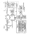
- a fuel cell system 10 includes a fuel cell stack 12, an oxygen-containing gas supply apparatus 14 for supplying an oxygen-containing gas to the fuel cell stack 12, a fuel gas supply apparatus 16 for supplying a fuel gas to the fuel cell stack 12, and a coolant supply apparatus (not shown) for supplying a coolant to the fuel cell stack 12, and an energy storage, e.g., a high voltage energy storage 18 which is capable of storing and discharging electrical energy generated by power generation of the fuel cell stack 12 and being directly coupled to the fuel cell stack 12, a group of loads 20 which consume at least electrical energy generated by the fuel cell stack 12 or electrical energy discharged from the high voltage energy storage 18, and a control device (controller) 22 for implementing the overall control of the fuel cell system 10.
- an energy storage e.g., a high voltage energy storage 18 which is capable of storing and discharging electrical energy generated by power generation of the fuel cell stack 12 and being directly coupled to the fuel cell stack 12, a group of loads 20 which consume at least electrical energy generated by the fuel cell stack 12 or electrical energy
- the fuel cell stack 12 is formed by stacking a plurality of fuel cells 24. Though not shown, each of the fuel cells 24 includes a membrane electrode assembly including an anode, a cathode, and a solid polymer electrolyte membrane interposed between the anode and the cathode. The membrane electrode assembly is sandwiched between a pair of separators.
- an oxygen-containing gas supply passage 26a for supplying an oxygen-containing gas such as the air and an oxygen-containing gas discharge passage 26b for discharging the oxygen-containing gas open.
- a fuel gas supply passage 28a for supplying the fuel gas such as a hydrogen-containing gas and a fuel gas discharge passage 28b for discharging the fuel gas open.
- the oxygen-containing gas supply passage 26a and the oxygen-containing gas discharge passage 26b are connected to an oxygen-containing gas flow field 30 formed between the membrane electrode assembly of each fuel cell 24 and one of the separators sandwiching the membrane electrode assembly.
- the fuel gas supply passage 28a and the fuel gas discharge passage 28b are connected to a fuel gas flow field 32 formed between the membrane electrode assembly of each fuel cell 24 and the other of the separators sandwiching the membrane electrode assembly.
- the oxygen-containing gas supply apparatus 14 includes an air compressor 34 for compressing the atmospheric air from the outside, and supplying the compressed air to the fuel cell stack 12.
- the air compressor 34 is provided in an air supply channel 36.
- the air supply channel 36 is connected to the oxygen-containing gas supply passage 26a of the fuel cell stack 12.
- the oxygen-containing gas supply apparatus 14 includes an air discharge channel 38 which is connected to the oxygen-containing gas discharge passage 26b.
- a back pressure control valve 40 is provided in the air discharge channel 38 for regulating the pressure of the air supplied from the air compressor 34 to the fuel cell stack 12 through the air supply channel 36.
- the fuel gas supply apparatus 16 includes a hydrogen tank 42 for storing a high pressure hydrogen (hydrogen-containing gas).
- the hydrogen tank 42 is connected to the fuel gas supply passage 28a of the fuel cell stack 12 through a hydrogen supply channel 44.
- An ejector 46 is provided in the hydrogen supply channel 44.
- the hydrogen gas is supplied from the hydrogen tank 42 to the ejector 46.
- the ejector 46 supplies the hydrogen gas to the fuel cell stack 12 through the hydrogen supply channel 44. Further, the ejector 46 sucks the exhaust gas containing the unconsumed hydrogen gas which has not been consumed in the fuel cell stack 12 such that the exhaust gas is discharged to a hydrogen circulation channel 48 connected to the fuel gas discharge passage 28b.
- the exhaust gas sucked by the ejector 46 is supplied again to the fuel cell stack 12.
- the group of loads 20 include, in addition to the air compressor 34, a pump 50 of the coolant supply apparatus, high voltage auxiliary devices 52 including an air conditioner, a heater 53. for heating the fuel cell stack 12, and a motor 54 for traveling.
- the fuel cell stack 12 and the group of loads 20 are connected through a first bus 56a.
- the high voltage energy storage 18 is connected to a position in the middle of the first bus 56a through a second bus 56b.
- a DC-DC converter 58 as a boosting converter which can increase the voltage of the electrical energy discharged from the high voltage energy storage 18 is provided in the second bus 56b.
- a capacitor such as an electric double layer capacitor or a battery is used as the high voltage energy storage 18.
- a group of low voltage auxiliary devices 59 such as an audio device and a light are provided in a position between the high voltage energy storage 18 and a DC-DC converter 58 through a down-converter 57.
- a first pressure sensor 60a is provided between the hydrogen tank 42 and the ejector 46, and a second pressure sensor 60b is provided between the ejector 46 and the fuel gas supply passage 28a of the fuel cell stack 12.
- a first temperature sensor 62a is provided near the fuel gas discharge passage 28b.
- first bus 56a a first voltage sensor 64a and a first current sensor 66a are provided near the fuel cell stack 12.
- a second current sensor 66b and a second voltage sensor 64b are provided near the high voltage energy storage 18.
- a second temperature sensor 62b for detecting the temperature of the high voltage energy storage 18 is provided in the high voltage energy storage 18.
- the control device 22 has functions of an auxiliary device control unit (remaining electrical energy amount reduction device) 70, a power generation control unit 72, a SOC calculation unit 74, an energy storage terminal voltage monitor unit 76, and a power generation state determination unit (power generation state determination device) 78.
- the auxiliary device control unit 70 is capable of decreasing the amount of remaining energy in the high voltage energy storage 18 to a predetermined value (described later) by any of the loads (described later).
- the power generation control unit 72 implements power generation control of the fuel cell stack 12.
- the SOC calculation unit 74 calculates the state of charge (SOC) in the high voltage energy storage 18.
- the energy storage terminal voltage monitor unit 76 monitors the terminal voltage of the high voltage energy storage 18.
- the power generation state determination unit 78 determines whether the fuel cell stack 12 performing power generation will be brought into a steady state or not based on whether operation of the fuel cell stack 12 is started at a temperature below the freezing point or not.
- step S1 when an ignition (not shown) of the fuel cell system 10 is turned on, (step S1), the process proceeds to step S2, and the power generation state determination unit 78 determines whether operation of the fuel cell stack 12 is started at a temperature below the freezing point or not.
- step S2 if it is determined that operation of the fuel cell stack 12 is started at a temperature below the freezing point (YES in step S2), i.e., if it is determined that operation of the fuel cell stack 12 will not be brought into a steady state, the process proceeds to step S3 to consume electrical energy in the high voltage energy storage 18 by the loads.
- the auxiliary device control unit 70 supplies electrical current from the high voltage energy storage 18 to loads of the group of loads 20, i.e., to the auxiliary devices such as the air compressor 34 and the pump 50 for operation of the fuel cell stack 12. Therefore, the rotation number of the air compressor 34 is increased. The air is increased and provided under high pressure, and energy consumption in the high voltage energy storage 18 is performed.
- electric current from the high voltage energy storage 18 is supplied to the external loads of the high voltage auxiliary devices 52 separately from operation of the fuel cell stack 12, such as an air conditioner heater or a fan to consume electrical energy in the high voltage energy storage 18. Further, by supplying electrical current to the heater 53, electrical energy in the high voltage energy storage 18 is consumed, and it is possible to warm up the fuel cell stack 12.
- the terminal voltage of the high voltage energy storage 18 changes depending on the state of charge (SOC). As the decrease in the amount of electrical energy in the high voltage energy storage 18, the terminal voltage of the high voltage energy storage 18 is decreased. Thus, in step S3, when electrical energy in the high voltage energy storage 18 is consumed by the loads, the terminal voltage of the high voltage energy storage 18 is decreased.
- the energy consumption may be performed before or after the supplying the fuel gas to the fuel cell stack 12, or may be performed before checking OCV (open circuit voltage).
- a SOC calculation unit 74 calculates the amount of electrical energy (charging amount) remaining in the high voltage energy storage 18 by the second current sensor 66b and the second voltage sensor 64b.
- an energy storage terminal voltage monitor unit 76 determines whether the terminal voltage of the high voltage energy storage 18 detected by the second voltage sensor 64b becomes a predetermined value or less.
- the predetermined value is close to the lower limit voltage outputted from the fuel cell stack 12 in the atmosphere at the temperature at which the electrical energy in the high voltage energy storage 18 is consumed as described above. If it is determined that the detected terminal voltage of the high voltage energy storage 18 is the predetermined voltage or less (YES in step S4), the process proceeds to step S5 to start power generation of the fuel cell stack 12.
- the air compressor 34 is driven.
- the compressed air supplied from the air compressor 34 is supplied to the oxygen-containing gas supply passage 26a of the fuel cell stack 12 through the air supply channel 36.
- the hydrogen gas supplied from the hydrogen tank 42 is supplied to the fuel gas supply passage 28a of the fuel cell stack 12 through the ejector 46 and the hydrogen supply channel 44.
- the air (oxygen-containing gas) supplied to the oxygen-containing gas supply passage 26a flows into the oxygen-containing gas flow field 30, and moves along the electrode surface of the cathode (not shown) for inducing an electrochemical reaction at the cathode. Then, the air is discharged into the oxygen-containing gas discharge passage 26b.
- the hydrogen gas (fuel gas) supplied to the fuel gas supply passage 28a moves along the electrode surface of the anode (not shown) of each fuel cell 24 for inducing an electrochemical reaction at the anode, and thereafter the hydrogen gas is discharged into the fuel gas discharge passage 28b.
- the electrochemical reactions of the oxygen in the air supplied to the cathode and the hydrogen supplied to the anode power generation is performed.
- the fuel gas discharge passage 28b of the fuel cell stack 12 is connected to the hydrogen circulation channel 48.
- the exhaust gas (exhaust fuel gas containing unconsumed hydrogen) discharged to the hydrogen circulation channel 48 returns to a position in the middle of the hydrogen supply channel 44 by sucking operation of the ejector 46, and then, the exhaust gas is supplied to the fuel cell stack 12 again as the fuel gas.
- step S6 by turning off the ignition, the power generation process in the fuel cell system 10 is finished.
- the process of decreasing the terminal voltage of the high voltage energy storage 18, i.e., the process of consuming electrical energy in the high voltage energy storage 18 by the loads is performed before starting power generation of the fuel cell stack 12.
- the terminal voltage of the high voltage energy storage 18 is decreased to a value close to the lower limit voltage of the fuel cell system 10.
- the range H1 of available power generation output of the fuel cell stack 12 is expanded to the range H2 of the available power generation output.
- the range of direct coupling between the fuel cell stack 12 and the high voltage energy storage 18 is sufficiently expanded, and it is possible to effectively increase the electrical current collected from the fuel cell stack 12.
- the fuel cell stack 12 is warmed up suitably, and it becomes possible to carry out continuous power generation reliably.
- the predetermined voltage may be the lower limit voltage of the fuel cell system 10 as the guaranteed operating voltage for the down-converter 57 connected between the DC-DC converter 58 and the high voltage energy storage 18 or the low voltage auxiliary devices 59.
- the lower limit voltage of the fuel cell system 10 is lower than the lower limit output voltage of the fuel cell stack 12 (see FIG. 5 ).
- control device 22 has functions of a warming up completion determining device for determining whether warming up of the high voltage energy storage 18 has been completed or not, and a voltage boosting restriction device for restricting increase in the voltage of the high voltage energy storage 18.
- step S11 to step S15 processes before power generation of the fuel cell stack 12 is started (step S11 to step S15) are performed in the same manner as the steps S1 to S5 of the first embodiment.
- step S16 determines whether it is necessary to restrict increase in the terminal voltage of the high voltage energy storage 18, e.g., based on whether warming up of the high voltage energy storage 18 has been completed or not.
- the high voltage energy storage 18 has characteristics in which as the increase in the charging amount, the terminal voltage of the high voltage energy storage 18 is increased. Further, while discharging electrical energy from the high voltage energy storage 18, the terminal voltage of the high voltage energy storage 18 is decreased temporarily, and while charging electrical energy in the high voltage energy storage 18, the terminal voltage of the high voltage energy voltage 18 is increased temporarily.
- the internal resistance of the high voltage energy storage 18 tends to become significantly high. Therefore, when the atmosphere around the fuel cell stack 12 is at a temperature below the freezing point, i.e., before warming up of the high voltage energy storage 18, if charging of the high voltage energy storage 18 is performed, the terminal voltage of the energy storage 18 is temporarily increased to a significantly large value. Thus, it may not be possible to collect electrically current from the fuel cell stack 12.
- the warming up completion determination device (control device) 22 determines whether warming up of the high voltage energy storage 18 has been completed or not based on the detected temperature by the second temperature sensor 62b. If it is determined that warming up of the high voltage energy storage 18 has not yet been completed, it is required to restrict increase in the terminal voltage of the high voltage energy storage 18 (YES, in step S16), and the process proceeds to step S17 for performing the process of restricting increase in the terminal voltage of the energy storage 18. As the process of restricting the terminal voltage of the high voltage energy storage 18, for example, without charging electrical energy in the high voltage energy storage 18, increase in the terminal voltage of the high voltage energy storage 18 is prevented. Alternatively, by discharging electrical energy from the high voltage energy storage 18, the terminal voltage of the high voltage energy storage 18 is decreased.
- step S16 determination as to whether increase in the terminal voltage of the energy storage 18 needs to be restricted or not may be performed not only based on determination of whether warming up of the high voltage energy storage 18 has been completed or not, but also whether the system is under control for starting operation at a temperature below the freezing point, the output voltage of the fuel cell stack 12 is equal to the terminal voltage of the high voltage energy storage 18, i.e., the system is in the direct coupling state, and whether the I-V characteristics of the fuel cell stack 12 are poor or not.
- whether the process proceeds to the step of consuming electrical energy in the high voltage energy storage 18 by the loads is determined based on whether operation of the fuel cell stack 12 is started at a temperature below the freezing point or not. Alternatively, the determination may be made based on whether the I-V characteristics of the fuel cell stack 12 are poor or not. At this time, the I-V characteristics during the previous power generation are used to determine whether the present I-V characteristics are poor or not.
- a fuel cell system (10) includes a fuel cell stack (12) for power generation by electrochemical reactions of a fuel gas and an oxygen-containing gas, a high voltage energy storage (18) capable of storing and discharging electrical energy generated by power generation of the fuel cell stack (12), and capable of being directly coupled to the fuel cell stack (12), a group of loads (20) consuming at least electrical energy generated by the fuel cell stack (12) or electrical energy discharged from the high voltage energy storage (18), and an auxiliary device control unit (70) for reducing an amount of electrical energy remaining in the energy storage (18) to a predetermined value by any of the group of loads (20), before starting power generation of the fuel cell stack (12).
Landscapes
- Life Sciences & Earth Sciences (AREA)
- Engineering & Computer Science (AREA)
- Sustainable Development (AREA)
- Sustainable Energy (AREA)
- Chemical & Material Sciences (AREA)
- Chemical Kinetics & Catalysis (AREA)
- Electrochemistry (AREA)
- General Chemical & Material Sciences (AREA)
- Manufacturing & Machinery (AREA)
- Fuel Cell (AREA)
- Secondary Cells (AREA)
Abstract
Description
- The present invention relates to a fuel cell system including a fuel cell, an energy storage, and a group of loads. The fuel cell performs power generation by electrochemical reactions of reactant gases. The energy storage is capable of storing and discharging electrical energy generated by the fuel cell, and capable of being directly coupled to the fuel cell. The group of loads consume at least electrical energy generated by the fuel cell or electrical energy discharged from the energy storage. Further, the present invention relates to a method of starting operation of the fuel cell system.
- The fuel cell is a system for obtaining direct current electrical energy by electrochemical reactions of a fuel gas (chiefly hydrogen-containing gas) supplied to an anode and an oxygen-containing gas supplied to a cathode.
- For example, a polymer electrolyte fuel cell includes a power generation cell formed by sandwiching a membrane electrode assembly between separators. The membrane electrode assembly includes the anode, and the cathode, and an electrolyte membrane interposed between the anode and the cathode. The electrolyte membrane is a solid polymer ion exchange membrane. In use of this type of the power generation cell, generally, predetermined numbers of the membrane electrode assemblies and separators are alternately stacked together to form a fuel cell stack.
- The fuel cell is promising in vehicle applications. For example, the fuel cell is mounted in a vehicle or the like. In the vehicle applications, power generation efficiency is high, and the exhaust gas is clean advantageously.
- In the fuel cell vehicle, a hybrid power supply system has been adopted. In the hybrid power supply system, in order to assist the output responsiveness or the like of the fuel cell, an energy storage such as a battery or a capacitor (electric double layer capacitor) is used in combination with the fuel cell. In this case, at the time of starting operation of the system, if the fuel cell is operated at a low temperature, power generation of the fuel cell may not be performed efficiently.
- In this regard, for example, a fuel cell system disclosed in Japanese Laid-Open Patent Publication No.
2004-281219 - According to the disclosure, at the time of starting operation of the system, it is possible to stabilize the fuel cell and raise the temperature of the fuel cell by self-heating. Also, it is possible to repeat charging and discharging the secondary battery and raise the temperature of the secondary battery by self-power generation. Therefore, the fuel cell and the secondary battery are effectively warmed up in a short period of time.
- In general, in the system, in a state where the output voltage of the fuel cell is equal to the terminal voltage of the battery (the fuel cell is directly coupled to the battery), it is no longer possible to further decrease the output voltage of the fuel cell from this state. Therefore, it is not possible to collect electrical current from the fuel cell.
- The energy storage such as a battery or a capacitor has characteristics in which as increase in the amount of charged electrical energy, the terminal voltage of the energy storage becomes high. In the fuel cell, the current -voltage characteristics (I-V characteristics) change depending on the temperature. In particular, at the time of starting operation of the fuel cell at a temperature below the freezing point, the I-V characteristics are significantly poor.
- Thus, as shown in
FIG. 8 , at the time of starting operation of the fuel cell at a temperature below the freezing point, the available output power generation range is very small. After collecting only a small amount of electrical current from the fuel cell, the potential of the output voltage of the fuel cell becomes equal to the potential of the terminal voltage of the energy storage. Thus, only small current can be colleted from the fuel cell. Self-heating of the fuel cell is not performed sufficiently, and continuous power generation cannot be performed suitably. -
US 2007/087232 A1 , on which the preamble ofclaims 1 and 6 is based, the temperature of the fuel cell is monitored. - In
JP 2006 344498 A US 2006/0280977 A1 , the temperature of the fuel cell is monitored. -
- In
US 2004/219409 A1 , a fuel cell system comprises asecondary battery 13 which is provided with aheater 15 to bring the battery on optimal operating temperature. At first, thesecondary battery 13 is heated and then the fuel cell 11 is heated to reduce warming time of the system. - The present invention has been made to solve the above problems, and an object of the present invention is to provide a fuel cell system and a method of starting operation of the fuel cell system in which, at the time of starting operation of the fuel cell system at low temperature, self-heating of the fuel cell is achieved easily and reliably, and continuous power generation is performed suitably.
- The present invention relates to a fuel cell system in accordance with claim 1 and methods in accordance with
claims - The fuel cell performs power generation by electrochemical reactions of reactant gases. The energy storage is capable of storing and discharging electrical energy generated by the fuel cell, and capable of being directly coupled to the fuel cell. The group of loads consume at least electrical energy generated by the fuel cell or electrical energy discharged from the energy storage.
- Further, the fuel cell system includes a remaining electrical energy amount reduction device for reducing an amount of electrical energy remaining in the energy storage to a predetermined value by any of the group of loads, before starting power generation of the fuel cell.
- According to the method of starting the fuel cell system of the present invention, before starting power generation of the fuel cell, the amount of electrical energy remaining in the energy storage is reduced to a predetermined value by any of the group of loads, and then, operation of the fuel cell is started.
- In the present invention, before starting power generation of the fuel cell, in order to reduce the amount of electrical energy remaining in the energy storage, the terminal voltage of the energy storage is decreased, and the available output power generation range of the fuel cell is expanded. Accordingly, it is possible to increase electrical current collected from the fuel cell. Further, in particular, at the time of starting operation at low temperature, self-heating of the fuel cell is achieved easily and reliably. Thus, it is possible to suitably warm up the fuel cell, and continuous power generation can be performed reliably.
- The above and other objects, features and advantages of the present invention will become more apparent from the following description when taken in conjunction with the accompanying drawings in which preferred embodiments of the present invention are shown by way of illustrative example.
-
-
FIG. 1 is a diagram schematically showing structure of a fuel cell system mounted in a vehicle according to embodiments of the present invention; -
FIG. 2 is a flow chart showing a method of starting operation according to a first embodiment of the present invention; -
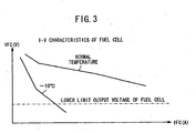
FIG. 3 is a graph showing I-V characteristics of a fuel cell depending on the change in the temperature; -
FIG. 4 is a graph showing characteristics of a high voltage energy storage; -
FIG. 5 is a graph showing I-V characteristics of a fuel cell when the terminal voltage of the high voltage energy storage is decreased; -
FIG. 6 is a flow chart showing a method of starting operation according to a second embodiment of the present invention; -
FIG. 7 is a graph showing the relationship between the internal resistance of the high voltage energy storage and the temperature of the high voltage energy storage; and -
FIG. 8 is a graph showing I-V characteristics of a normal fuel cell. - As shown in
FIG. 1 , afuel cell system 10 includes afuel cell stack 12, an oxygen-containinggas supply apparatus 14 for supplying an oxygen-containing gas to thefuel cell stack 12, a fuelgas supply apparatus 16 for supplying a fuel gas to thefuel cell stack 12, and a coolant supply apparatus (not shown) for supplying a coolant to thefuel cell stack 12, and an energy storage, e.g., a highvoltage energy storage 18 which is capable of storing and discharging electrical energy generated by power generation of thefuel cell stack 12 and being directly coupled to thefuel cell stack 12, a group of loads 20 which consume at least electrical energy generated by thefuel cell stack 12 or electrical energy discharged from the highvoltage energy storage 18, and a control device (controller) 22 for implementing the overall control of thefuel cell system 10. - The
fuel cell stack 12 is formed by stacking a plurality offuel cells 24. Though not shown, each of thefuel cells 24 includes a membrane electrode assembly including an anode, a cathode, and a solid polymer electrolyte membrane interposed between the anode and the cathode. The membrane electrode assembly is sandwiched between a pair of separators. - At one end of the
fuel cell stack 12 in the stacking direction, an oxygen-containinggas supply passage 26a for supplying an oxygen-containing gas such as the air and an oxygen-containinggas discharge passage 26b for discharging the oxygen-containing gas open. At the other end of thefuel cell stack 12 in the stacking direction, a fuelgas supply passage 28a for supplying the fuel gas such as a hydrogen-containing gas and a fuelgas discharge passage 28b for discharging the fuel gas open. - The oxygen-containing
gas supply passage 26a and the oxygen-containinggas discharge passage 26b are connected to an oxygen-containinggas flow field 30 formed between the membrane electrode assembly of eachfuel cell 24 and one of the separators sandwiching the membrane electrode assembly. The fuelgas supply passage 28a and the fuelgas discharge passage 28b are connected to a fuelgas flow field 32 formed between the membrane electrode assembly of eachfuel cell 24 and the other of the separators sandwiching the membrane electrode assembly. - The oxygen-containing
gas supply apparatus 14 includes anair compressor 34 for compressing the atmospheric air from the outside, and supplying the compressed air to thefuel cell stack 12. Theair compressor 34 is provided in anair supply channel 36. Theair supply channel 36 is connected to the oxygen-containinggas supply passage 26a of thefuel cell stack 12. - The oxygen-containing
gas supply apparatus 14 includes anair discharge channel 38 which is connected to the oxygen-containinggas discharge passage 26b. A backpressure control valve 40 is provided in theair discharge channel 38 for regulating the pressure of the air supplied from theair compressor 34 to thefuel cell stack 12 through theair supply channel 36. - The fuel
gas supply apparatus 16 includes ahydrogen tank 42 for storing a high pressure hydrogen (hydrogen-containing gas). Thehydrogen tank 42 is connected to the fuelgas supply passage 28a of thefuel cell stack 12 through ahydrogen supply channel 44. Anejector 46 is provided in thehydrogen supply channel 44. The hydrogen gas is supplied from thehydrogen tank 42 to theejector 46. Theejector 46 supplies the hydrogen gas to thefuel cell stack 12 through thehydrogen supply channel 44. Further, theejector 46 sucks the exhaust gas containing the unconsumed hydrogen gas which has not been consumed in thefuel cell stack 12 such that the exhaust gas is discharged to ahydrogen circulation channel 48 connected to the fuelgas discharge passage 28b. The exhaust gas sucked by theejector 46 is supplied again to thefuel cell stack 12. - The group of loads 20 include, in addition to the
air compressor 34, apump 50 of the coolant supply apparatus, high voltageauxiliary devices 52 including an air conditioner, aheater 53. for heating thefuel cell stack 12, and amotor 54 for traveling. - The
fuel cell stack 12 and the group of loads 20 are connected through afirst bus 56a. The highvoltage energy storage 18 is connected to a position in the middle of thefirst bus 56a through asecond bus 56b. Further, a DC-DC converter 58 as a boosting converter which can increase the voltage of the electrical energy discharged from the highvoltage energy storage 18 is provided in thesecond bus 56b. For example, a capacitor such as an electric double layer capacitor or a battery is used as the highvoltage energy storage 18. In thesecond bus 56b, a group of low voltageauxiliary devices 59 such as an audio device and a light are provided in a position between the highvoltage energy storage 18 and a DC-DC converter 58 through a down-converter 57. - In the fuel
gas supply apparatus 16, afirst pressure sensor 60a is provided between thehydrogen tank 42 and theejector 46, and asecond pressure sensor 60b is provided between theejector 46 and the fuelgas supply passage 28a of thefuel cell stack 12. In ahydrogen circulation channel 48, afirst temperature sensor 62a is provided near the fuelgas discharge passage 28b. - In the
first bus 56a, afirst voltage sensor 64a and a firstcurrent sensor 66a are provided near thefuel cell stack 12. In thesecond bus 56b, a secondcurrent sensor 66b and asecond voltage sensor 64b are provided near the highvoltage energy storage 18. Further, asecond temperature sensor 62b for detecting the temperature of the highvoltage energy storage 18 is provided in the highvoltage energy storage 18. - The
control device 22 has functions of an auxiliary device control unit (remaining electrical energy amount reduction device) 70, a powergeneration control unit 72, aSOC calculation unit 74, an energy storage terminalvoltage monitor unit 76, and a power generation state determination unit (power generation state determination device) 78. The auxiliarydevice control unit 70 is capable of decreasing the amount of remaining energy in the highvoltage energy storage 18 to a predetermined value (described later) by any of the loads (described later). The powergeneration control unit 72 implements power generation control of thefuel cell stack 12. TheSOC calculation unit 74 calculates the state of charge (SOC) in the highvoltage energy storage 18. The energy storage terminalvoltage monitor unit 76 monitors the terminal voltage of the highvoltage energy storage 18. The power generationstate determination unit 78 determines whether thefuel cell stack 12 performing power generation will be brought into a steady state or not based on whether operation of thefuel cell stack 12 is started at a temperature below the freezing point or not. - Next, operation of the
fuel cell system 10 will be descried in connection with a method of starting operation of a fuel cell system according to the first embodiment of the present invention with reference to a flow chart inFIG. 2 . - Firstly, when an ignition (not shown) of the
fuel cell system 10 is turned on, (step S1), the process proceeds to step S2, and the power generationstate determination unit 78 determines whether operation of thefuel cell stack 12 is started at a temperature below the freezing point or not. - As shown in
FIG. 3 , in comparison with the normal temperature, the I-V characteristics of the fuel cell 24 (current-voltage characteristic) are significantly poor at low temperature, in particular, below the freezing point. Thus, in step S2, if it is determined that operation of thefuel cell stack 12 is started at a temperature below the freezing point (YES in step S2), i.e., if it is determined that operation of thefuel cell stack 12 will not be brought into a steady state, the process proceeds to step S3 to consume electrical energy in the highvoltage energy storage 18 by the loads. - Specifically, the auxiliary
device control unit 70 supplies electrical current from the highvoltage energy storage 18 to loads of the group of loads 20, i.e., to the auxiliary devices such as theair compressor 34 and thepump 50 for operation of thefuel cell stack 12. Therefore, the rotation number of theair compressor 34 is increased. The air is increased and provided under high pressure, and energy consumption in the highvoltage energy storage 18 is performed. - Further, electric current from the high
voltage energy storage 18 is supplied to the external loads of the high voltageauxiliary devices 52 separately from operation of thefuel cell stack 12, such as an air conditioner heater or a fan to consume electrical energy in the highvoltage energy storage 18. Further, by supplying electrical current to theheater 53, electrical energy in the highvoltage energy storage 18 is consumed, and it is possible to warm up thefuel cell stack 12. - In this case, as shown in
FIG. 4 , the terminal voltage of the highvoltage energy storage 18 changes depending on the state of charge (SOC). As the decrease in the amount of electrical energy in the highvoltage energy storage 18, the terminal voltage of the highvoltage energy storage 18 is decreased. Thus, in step S3, when electrical energy in the highvoltage energy storage 18 is consumed by the loads, the terminal voltage of the highvoltage energy storage 18 is decreased. - As long as the electrical energy in the high
voltage energy storage 18 is consumed by the load substantially before starting of the power operation of thefuel cell stack 12, the energy consumption may be performed before or after the supplying the fuel gas to thefuel cell stack 12, or may be performed before checking OCV (open circuit voltage). - A
SOC calculation unit 74 calculates the amount of electrical energy (charging amount) remaining in the highvoltage energy storage 18 by the secondcurrent sensor 66b and thesecond voltage sensor 64b. In step S4, an energy storage terminalvoltage monitor unit 76 determines whether the terminal voltage of the highvoltage energy storage 18 detected by thesecond voltage sensor 64b becomes a predetermined value or less. - The predetermined value is close to the lower limit voltage outputted from the
fuel cell stack 12 in the atmosphere at the temperature at which the electrical energy in the highvoltage energy storage 18 is consumed as described above. If it is determined that the detected terminal voltage of the highvoltage energy storage 18 is the predetermined voltage or less (YES in step S4), the process proceeds to step S5 to start power generation of thefuel cell stack 12. - As shown in
FIG. 1 , in the oxygen-containinggas supply apparatus 14, theair compressor 34 is driven. The compressed air supplied from theair compressor 34 is supplied to the oxygen-containinggas supply passage 26a of thefuel cell stack 12 through theair supply channel 36. In the fuelgas supply apparatus 16, the hydrogen gas supplied from thehydrogen tank 42 is supplied to the fuelgas supply passage 28a of thefuel cell stack 12 through theejector 46 and thehydrogen supply channel 44. - In each of the
fuel cells 24 of thefuel cell stack 12, the air (oxygen-containing gas) supplied to the oxygen-containinggas supply passage 26a flows into the oxygen-containinggas flow field 30, and moves along the electrode surface of the cathode (not shown) for inducing an electrochemical reaction at the cathode. Then, the air is discharged into the oxygen-containinggas discharge passage 26b. - The hydrogen gas (fuel gas) supplied to the fuel
gas supply passage 28a moves along the electrode surface of the anode (not shown) of eachfuel cell 24 for inducing an electrochemical reaction at the anode, and thereafter the hydrogen gas is discharged into the fuelgas discharge passage 28b. Thus, in each of thefuel cells 24, by the electrochemical reactions of the oxygen in the air supplied to the cathode and the hydrogen supplied to the anode, power generation is performed. - The fuel
gas discharge passage 28b of thefuel cell stack 12 is connected to thehydrogen circulation channel 48. Thus, the exhaust gas (exhaust fuel gas containing unconsumed hydrogen) discharged to thehydrogen circulation channel 48 returns to a position in the middle of thehydrogen supply channel 44 by sucking operation of theejector 46, and then, the exhaust gas is supplied to thefuel cell stack 12 again as the fuel gas. - As described above, power generation is performed in each of the
fuel cells 24, and thefuel cell stack 12 is warmed up by self-heating. By supplying electrical energy generated by power generation from thefuel cell stack 12 to themotor 54 through thefirst bus 56a, normal operation by thefuel cell system 10 is performed. Thereafter, in step S6, by turning off the ignition, the power generation process in thefuel cell system 10 is finished. - In the first embodiment, before starting power generation of the
fuel cell stack 12, the process of decreasing the terminal voltage of the highvoltage energy storage 18, i.e., the process of consuming electrical energy in the highvoltage energy storage 18 by the loads is performed. Thus, as shown inFIG. 5 , the terminal voltage of the highvoltage energy storage 18 is decreased to a value close to the lower limit voltage of thefuel cell system 10. Thus, the range H1 of available power generation output of thefuel cell stack 12 is expanded to the range H2 of the available power generation output. - Thus, the range of direct coupling between the
fuel cell stack 12 and the highvoltage energy storage 18 is sufficiently expanded, and it is possible to effectively increase the electrical current collected from thefuel cell stack 12. Thus, in particular, at the time of starting operation of thefuel cell stack 12 at low temperature, it is possible to reliably and easily induce self-heating of thefuel cell stack 12. Thefuel cell stack 12 is warmed up suitably, and it becomes possible to carry out continuous power generation reliably. - Since the voltage of the DC-
DC converter 58 can be boosted (increased), the predetermined voltage may be the lower limit voltage of thefuel cell system 10 as the guaranteed operating voltage for the down-converter 57 connected between the DC-DC converter 58 and the highvoltage energy storage 18 or the low voltageauxiliary devices 59. The lower limit voltage of thefuel cell system 10 is lower than the lower limit output voltage of the fuel cell stack 12 (seeFIG. 5 ). - Next, a method of starting operation of the
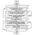
fuel cell stack 12 according to a second embodiment will be described with reference to a flow chart inFIG. 6 . - In the second embodiment, the
control device 22 has functions of a warming up completion determining device for determining whether warming up of the highvoltage energy storage 18 has been completed or not, and a voltage boosting restriction device for restricting increase in the voltage of the highvoltage energy storage 18. - Firstly, after the ignition is turned on, processes before power generation of the
fuel cell stack 12 is started (step S11 to step S15) are performed in the same manner as the steps S1 to S5 of the first embodiment. - Further, after power generation of the
fuel cell stack 12 is started, the process proceeds to step S16 to determine whether it is necessary to restrict increase in the terminal voltage of the highvoltage energy storage 18, e.g., based on whether warming up of the highvoltage energy storage 18 has been completed or not. - As shown in
FIG. 4 , the highvoltage energy storage 18 has characteristics in which as the increase in the charging amount, the terminal voltage of the highvoltage energy storage 18 is increased. Further, while discharging electrical energy from the highvoltage energy storage 18, the terminal voltage of the highvoltage energy storage 18 is decreased temporarily, and while charging electrical energy in the highvoltage energy storage 18, the terminal voltage of the highvoltage energy voltage 18 is increased temporarily. - As shown in
FIG. 7 , as the decrease in the temperature, specifically, as the decrease in the temperature below the freezing point, the internal resistance of the highvoltage energy storage 18 tends to become significantly high. Therefore, when the atmosphere around thefuel cell stack 12 is at a temperature below the freezing point, i.e., before warming up of the highvoltage energy storage 18, if charging of the highvoltage energy storage 18 is performed, the terminal voltage of theenergy storage 18 is temporarily increased to a significantly large value. Thus, it may not be possible to collect electrically current from thefuel cell stack 12. - Then, the warming up completion determination device (control device) 22 determines whether warming up of the high
voltage energy storage 18 has been completed or not based on the detected temperature by thesecond temperature sensor 62b. If it is determined that warming up of the highvoltage energy storage 18 has not yet been completed, it is required to restrict increase in the terminal voltage of the high voltage energy storage 18 (YES, in step S16), and the process proceeds to step S17 for performing the process of restricting increase in the terminal voltage of theenergy storage 18. As the process of restricting the terminal voltage of the highvoltage energy storage 18, for example, without charging electrical energy in the highvoltage energy storage 18, increase in the terminal voltage of the highvoltage energy storage 18 is prevented. Alternatively, by discharging electrical energy from the highvoltage energy storage 18, the terminal voltage of the highvoltage energy storage 18 is decreased. - It is necessary to control discharging of the high
voltage energy storage 18 such that the terminal voltage of the highvoltage energy storage 18 does not become the lower limit voltage of thefuel cell system 10 or less. By turning off the ignition (YES in step S18), warming up of thefuel cell system 10 is finished. - Thus, in the second embodiment, after starting power generation of the
fuel cell stack 12, until completion of warming up of the highvoltage energy storage 18, increase in the terminal voltage of the highvoltage energy storage 18 is restricted. Thus, in thefuel cell stack 12, it is possible to collect electrical current even at low voltage. Accordingly, warming up of thefuel cell stack 12 is performed reliably, and power generation continues suitably. - In step S16, determination as to whether increase in the terminal voltage of the
energy storage 18 needs to be restricted or not may be performed not only based on determination of whether warming up of the highvoltage energy storage 18 has been completed or not, but also whether the system is under control for starting operation at a temperature below the freezing point, the output voltage of thefuel cell stack 12 is equal to the terminal voltage of the highvoltage energy storage 18, i.e., the system is in the direct coupling state, and whether the I-V characteristics of thefuel cell stack 12 are poor or not. - In the first and second embodiments, whether the process proceeds to the step of consuming electrical energy in the high
voltage energy storage 18 by the loads is determined based on whether operation of thefuel cell stack 12 is started at a temperature below the freezing point or not. Alternatively, the determination may be made based on whether the I-V characteristics of thefuel cell stack 12 are poor or not. At this time, the I-V characteristics during the previous power generation are used to determine whether the present I-V characteristics are poor or not. - A fuel cell system (10) includes a fuel cell stack (12) for power generation by electrochemical reactions of a fuel gas and an oxygen-containing gas, a high voltage energy storage (18) capable of storing and discharging electrical energy generated by power generation of the fuel cell stack (12), and capable of being directly coupled to the fuel cell stack (12), a group of loads (20) consuming at least electrical energy generated by the fuel cell stack (12) or electrical energy discharged from the high voltage energy storage (18), and an auxiliary device control unit (70) for reducing an amount of electrical energy remaining in the energy storage (18) to a predetermined value by any of the group of loads (20), before starting power generation of the fuel cell stack (12).
Claims (14)
- A fuel cell system comprising:a fuel cell (24) for performing power generation by electrochemical reactions of reactant gases supplied to said fuel cell (24);an energy storage (18) capable of storing and discharging electrical energy generated by power generation of said fuel cell (24), andcapable of being directly coupled to said fuel cell (24);a group of loads (20) consuming at least electrical energy generated by said fuel cell (24) or electrical energy discharged from said energy storage (18); anda remaining electrical energy amount reduction device (70) for reducing an amount of electrical energy remaining in said energy storage (18) to a predetermined value by any of said group of loads (20), before starting power generation of said fuel cell (24), characterized by a warming up completion determination device (22) for determining whether warming up of said energy storage (18) has been completed or not, anda voltage boosting restriction device (22) for restricting increase in voltage of said energy storage (18) when said warming up completion determination device (22) determines that warming up of said energy storage (18) has not yet been completed.
- A fuel cell system according to claim 1, further comprising a power generation state determining device (78) for determining whether said fuel cell (24) performing power generation will, be brought into a steady state or not before starting operation of said fuel cell (24), wherein if it is determined that said fuel cell (24) will not be brought into the steady state, the electrical energy amount remaining in said energy storage (18) is reduced by said remaining electrical energy amount reduction device (70).
- A fuel cell system according to claim 2, wherein said power generation state determination device (78) determines that said fuel cell (24) will not be brought into the steady state when operation of said fuel cell (24) is started at a temperature below the freezing point.
- A fuel cell system according to claim 1, wherein the predetermined value is a value to achieve a state in which at least terminal voltage of said energy storage (18) becomes equal to lower limit output voltage of said fuel cell (24) or lower limit voltage of said fuel cell system.
- A fuel cell system according to claim 1, further comprising a first bus (56a) connecting said fuel cell (24) and said group of loads (20);
a second bus (56b) connecting a position in the middle of said first bus (56a) and said energy storage (18); and
a converter (58) provided in said second bus (56b), said converter (58) being capable of boosting voltage for discharging electrical energy from said energy storage (18). - A method of starting operation of a full cell system comprising:a fuel cell (24) for performing power generation by electrochemical reactions of reactant gases supplied to said fuel cell (24);an energy storage (18) capable of storing and discharging electrical energy generated by power generation of said fuel cell (24), and capable of being directly coupled to said fuel cell (24); anda group of loads (20) consuming at least electrical energy generated by said fuel cell (24) or electrical energy discharged from said energy storage (18), the method comprising the steps of:reducing an amount of electrical energy remaining in said energy storage (18) to a predetermined value by any of said group of loads (20) before starting power generation of said fuel cell (24); and thereafter,starting operation of said fuel cell (24),characterized by the steps ofdetermining whether warming up of said energy storage (18) has been completed or not; andrestricting increase in voltage of said energy storage (18) when it is determined that warming up of said energy storage (18) has not yet been completed.
- A method of starting operation of said full cell system according to claim 6, further comprising the steps of:determining whether said fuel cell (24) performing power generation will be brought into a steady state or not before starting operation of said fuel cell (24); andreducing electrical energy amount remaining in said energy storage (18) if it is determined that said fuel cell (24) will not be brought into the steady state.
- A method of starting operation of said full cell system according to claim 7, wherein it is determined that said fuel cell (24) will not be brought into the steady state when operation of said fuel cell (24) is started at a temperature below the freezing point.
- A method of starting operation of said full cell system according to claim 6, wherein the predetermined value is a value to achieve a state in which at least terminal voltage of said energy storage (18) becomes equal to lower limit output voltage of said fuel cell (24).
- A method of starting operation of a full cell system comprising:a fuel cell (24) for performing power generation by electrochemical reactions of reactant gases supplied to said fuel cell (24);an energy storage (18) capable of storing and discharging electrical energy generated by power generation of said fuel cell (24), andcapable of being directly coupled to said fuel cell (24); anda group of loads (20) consuming at least electrical energy generated by said fuel cell (24) or electrical energy discharged from said energy storage (18), the method comprising the steps of:reducing an amount of electrical energy remaining in said energy storage (18) to a predetermined value by any of said group of loads (20) before starting power generation of said fuel cell (24), said predetermined value being a value to achieve a state in which at least terminal voltage of said energy storage (18) becomes equal to lower limit output voltage of said fuel cell (24) or lower limit voltage of said fuel cell system; and thereafter, starting operation of said fuel cell (24).
- A method of starting operation of said full cell system according to claim 10, further comprising the steps of:determining whether said fuel cell (24) performing power generation will be brought into a steady state or not before starting operation of said fuel cell (24); andreducing electrical energy amount remaining in said energy storage (18) if it is determined that said fuel cell (24) will not be brought into the steady state.
- A method of starting operation of said full cell system according to claim 11,
wherein it is determined that said fuel cell (24) will not be brought into the steady state when operation of said fuel cell (24) is started at a temperature below the freezing point. - A method of starting operation of said full cell system according to claim 10, further comprising the step of restricting increase in voltage of said energy storage (18).
- A method of starting operation of said full cell system according to claim 13, further comprising the steps of
determining whether warming up of said energy storage (18) has been completed or not; and
restricting increase in voltage of said energy storage (18) when it is determined that warming up of said energy storage (18) has not yet been completed.
Applications Claiming Priority (1)
| Application Number | Priority Date | Filing Date | Title |
|---|---|---|---|
| JP2007135595A JP4516093B2 (en) | 2007-05-22 | 2007-05-22 | Fuel cell system and starting method thereof |
Publications (2)
| Publication Number | Publication Date |
|---|---|
| EP1998397A1 EP1998397A1 (en) | 2008-12-03 |
| EP1998397B1 true EP1998397B1 (en) | 2011-06-22 |
Family
ID=39735193
Family Applications (1)
| Application Number | Title | Priority Date | Filing Date |
|---|---|---|---|
| EP08009411A Not-in-force EP1998397B1 (en) | 2007-05-22 | 2008-05-21 | Fuel cell system and method of starting operation of fuel cell system |
Country Status (4)
| Country | Link |
|---|---|
| US (1) | US7816884B2 (en) |
| EP (1) | EP1998397B1 (en) |
| JP (1) | JP4516093B2 (en) |
| AT (1) | ATE514201T1 (en) |
Families Citing this family (9)
| Publication number | Priority date | Publication date | Assignee | Title |
|---|---|---|---|---|
| JP4505489B2 (en) * | 2007-09-10 | 2010-07-21 | 本田技研工業株式会社 | Fuel cell system and starting method thereof |
| JP4444343B2 (en) * | 2008-04-25 | 2010-03-31 | 本田技研工業株式会社 | Fuel cell vehicle |
| US8072224B2 (en) * | 2008-08-04 | 2011-12-06 | Toyoto Motor Engineering & Manufacturing North America, Inc. | Methods for predicting the future performance of fuel cell stacks and individual fuel cells |
| CN102340018A (en) * | 2010-07-15 | 2012-02-01 | 中兴电工机械股份有限公司 | Series system of multiple group fuel cell converters and control method thereof |
| JP2013254714A (en) * | 2012-06-08 | 2013-12-19 | Asahi Kasei E-Materials Corp | Fuel cell system |
| EP2988353B1 (en) * | 2013-04-16 | 2018-03-14 | Nissan Motor Co., Ltd | Fuel-cell system and method for controlling fuel-cell system |
| JP6361686B2 (en) * | 2016-04-22 | 2018-07-25 | トヨタ自動車株式会社 | Fuel cell system |
| CN110406429A (en) * | 2018-04-25 | 2019-11-05 | 天津银隆新能源有限公司 | High-efficiency low-temperature starting system and control method for extended-range fuel cell vehicles |
| JP7036929B2 (en) * | 2019-02-28 | 2022-03-15 | 京セラ株式会社 | Fuel cell device |
Family Cites Families (19)
| Publication number | Priority date | Publication date | Assignee | Title |
|---|---|---|---|---|
| ATE298291T1 (en) * | 1998-04-17 | 2005-07-15 | Siemens Ag | METHOD FOR STARTING A FUEL CELL SYSTEM AND FUEL CELL SYSTEM |
| JP3661643B2 (en) * | 2001-12-27 | 2005-06-15 | 日産自動車株式会社 | Fuel cell system |
| JP4131110B2 (en) * | 2002-02-28 | 2008-08-13 | 株式会社エクォス・リサーチ | Fuel cell stack |
| JP3922108B2 (en) * | 2002-06-19 | 2007-05-30 | 日産自動車株式会社 | Control device for fuel cell system |
| JP3832417B2 (en) * | 2002-10-22 | 2006-10-11 | 日産自動車株式会社 | Fuel cell system |
| JP2004146118A (en) * | 2002-10-22 | 2004-05-20 | Nissan Motor Co Ltd | Fuel cell system |
| JP3857214B2 (en) | 2002-10-31 | 2006-12-13 | 本田技研工業株式会社 | How to warm up a fuel cell system |
| JP4626125B2 (en) * | 2003-03-14 | 2011-02-02 | 日産自動車株式会社 | Fuel cell system |
| JP2004311218A (en) * | 2003-04-07 | 2004-11-04 | Toyota Industries Corp | Warming-up device for fuel cell system |
| JP2004342461A (en) * | 2003-05-15 | 2004-12-02 | Nissan Motor Co Ltd | Fuel cell system |
| JP4193639B2 (en) * | 2003-08-28 | 2008-12-10 | 日産自動車株式会社 | Control device for vehicle equipped with fuel cell |
| US7446501B2 (en) * | 2004-03-19 | 2008-11-04 | More Energy Ltd. | Integrated fuel cell controller for devices |
| JP4397739B2 (en) * | 2004-06-03 | 2010-01-13 | 本田技研工業株式会社 | Method for setting voltage state of fuel cell vehicle |
| JP2006114486A (en) * | 2004-09-17 | 2006-04-27 | Seiko Instruments Inc | Fuel cell power supply system |
| JP4613694B2 (en) * | 2005-05-25 | 2011-01-19 | トヨタ自動車株式会社 | Fuel cell vehicle and control method thereof |
| JP2006344498A (en) * | 2005-06-09 | 2006-12-21 | Denso Corp | Fuel cell system |
| US20070087232A1 (en) * | 2005-10-18 | 2007-04-19 | Robin Curtis M | Capacitor hybrid fuel cell power generator |
| JP5215583B2 (en) * | 2007-04-06 | 2013-06-19 | 本田技研工業株式会社 | Fuel cell system |
| JP4505489B2 (en) * | 2007-09-10 | 2010-07-21 | 本田技研工業株式会社 | Fuel cell system and starting method thereof |
-
2007
- 2007-05-22 JP JP2007135595A patent/JP4516093B2/en not_active Expired - Fee Related
-
2008
- 2008-05-21 AT AT08009411T patent/ATE514201T1/en not_active IP Right Cessation
- 2008-05-21 EP EP08009411A patent/EP1998397B1/en not_active Not-in-force
- 2008-05-22 US US12/125,668 patent/US7816884B2/en not_active Expired - Fee Related
Also Published As
| Publication number | Publication date |
|---|---|
| ATE514201T1 (en) | 2011-07-15 |
| JP4516093B2 (en) | 2010-08-04 |
| US20080290832A1 (en) | 2008-11-27 |
| JP2008293695A (en) | 2008-12-04 |
| EP1998397A1 (en) | 2008-12-03 |
| US7816884B2 (en) | 2010-10-19 |
Similar Documents
| Publication | Publication Date | Title |
|---|---|---|
| EP1998397B1 (en) | Fuel cell system and method of starting operation of fuel cell system | |
| US8415065B2 (en) | Fuel cell system and method of controlling fuel cell system | |
| US11108063B2 (en) | Fuel cell system | |
| CA2662903C (en) | Fuel cell system with low-efficiency operation control and its operation method | |
| CN104205454B (en) | Fuel cell system | |
| CN101322272B (en) | Fuel cell system | |
| CN101326662B (en) | Fuel cell system | |
| US20160181636A1 (en) | Open-loop system and method for fuel cell stack start-up with low-voltage source | |
| JP2002313388A (en) | Fuel cell control method and fuel cell electric vehicle | |
| CN101322275B (en) | Fuel cell system and mobile body | |
| US20100316921A1 (en) | Fuel cell system | |
| US8258740B2 (en) | Fuel cell system and method of starting operation of fuel cell system | |
| CA2553057C (en) | Fuel cell system and charge amount adjustment method for energy storage | |
| US20060021812A1 (en) | Fuel cell vehicle and control method thereof | |
| US20080118798A1 (en) | Fuel cell system apparatus | |
| US7776481B2 (en) | Fuel cell system and method of controlling electrical energy discharged in the fuel cell system | |
| US7078116B2 (en) | Method of warming up fuel cell system | |
| US11705562B2 (en) | Fuel cell system | |
| JP5773278B2 (en) | Fuel cell system and control method thereof | |
| JP2009129679A (en) | Fuel cell system | |
| JP2007250216A (en) | Fuel cell system and operation method thereof | |
| JP2009104977A (en) | Fuel cell system | |
| JP2009224169A (en) | Fuel cell system |
Legal Events
| Date | Code | Title | Description |
|---|---|---|---|
| PUAI | Public reference made under article 153(3) epc to a published international application that has entered the european phase |
Free format text: ORIGINAL CODE: 0009012 |
|
| 17P | Request for examination filed |
Effective date: 20080521 |
|
| AK | Designated contracting states |
Kind code of ref document: A1 Designated state(s): AT BE BG CH CY CZ DE DK EE ES FI FR GB GR HR HU IE IS IT LI LT LU LV MC MT NL NO PL PT RO SE SI SK TR |
|
| AX | Request for extension of the european patent |
Extension state: AL BA MK RS |
|
| 17Q | First examination report despatched |
Effective date: 20081124 |
|
| AKX | Designation fees paid |
Designated state(s): AT BE BG CH CY CZ DE DK EE ES FI FR GB GR HR HU IE IS IT LI LT LU LV MC MT NL NO PL PT RO SE SI SK TR |
|
| GRAP | Despatch of communication of intention to grant a patent |
Free format text: ORIGINAL CODE: EPIDOSNIGR1 |
|
| GRAS | Grant fee paid |
Free format text: ORIGINAL CODE: EPIDOSNIGR3 |
|
| GRAA | (expected) grant |
Free format text: ORIGINAL CODE: 0009210 |
|
| RAP1 | Party data changed (applicant data changed or rights of an application transferred) |
Owner name: HONDA MOTOR CO., LTD. |
|
| AK | Designated contracting states |
Kind code of ref document: B1 Designated state(s): AT BE BG CH CY CZ DE DK EE ES FI FR GB GR HR HU IE IS IT LI LT LU LV MC MT NL NO PL PT RO SE SI SK TR |
|
| REG | Reference to a national code |
Ref country code: GB Ref legal event code: FG4D |
|
| REG | Reference to a national code |
Ref country code: CH Ref legal event code: EP |
|
| REG | Reference to a national code |
Ref country code: IE Ref legal event code: FG4D |
|
| REG | Reference to a national code |
Ref country code: DE Ref legal event code: R096 Ref document number: 602008007721 Country of ref document: DE Effective date: 20110804 |
|
| REG | Reference to a national code |
Ref country code: NL Ref legal event code: VDEP Effective date: 20110622 |
|
| PG25 | Lapsed in a contracting state [announced via postgrant information from national office to epo] |
Ref country code: NO Free format text: LAPSE BECAUSE OF FAILURE TO SUBMIT A TRANSLATION OF THE DESCRIPTION OR TO PAY THE FEE WITHIN THE PRESCRIBED TIME-LIMIT Effective date: 20110922 Ref country code: HR Free format text: LAPSE BECAUSE OF FAILURE TO SUBMIT A TRANSLATION OF THE DESCRIPTION OR TO PAY THE FEE WITHIN THE PRESCRIBED TIME-LIMIT Effective date: 20110622 Ref country code: SE Free format text: LAPSE BECAUSE OF FAILURE TO SUBMIT A TRANSLATION OF THE DESCRIPTION OR TO PAY THE FEE WITHIN THE PRESCRIBED TIME-LIMIT Effective date: 20110622 Ref country code: LT Free format text: LAPSE BECAUSE OF FAILURE TO SUBMIT A TRANSLATION OF THE DESCRIPTION OR TO PAY THE FEE WITHIN THE PRESCRIBED TIME-LIMIT Effective date: 20110622 |
|
| PG25 | Lapsed in a contracting state [announced via postgrant information from national office to epo] |
Ref country code: AT Free format text: LAPSE BECAUSE OF FAILURE TO SUBMIT A TRANSLATION OF THE DESCRIPTION OR TO PAY THE FEE WITHIN THE PRESCRIBED TIME-LIMIT Effective date: 20110622 Ref country code: CY Free format text: LAPSE BECAUSE OF FAILURE TO SUBMIT A TRANSLATION OF THE DESCRIPTION OR TO PAY THE FEE WITHIN THE PRESCRIBED TIME-LIMIT Effective date: 20110622 Ref country code: FI Free format text: LAPSE BECAUSE OF FAILURE TO SUBMIT A TRANSLATION OF THE DESCRIPTION OR TO PAY THE FEE WITHIN THE PRESCRIBED TIME-LIMIT Effective date: 20110622 Ref country code: GR Free format text: LAPSE BECAUSE OF FAILURE TO SUBMIT A TRANSLATION OF THE DESCRIPTION OR TO PAY THE FEE WITHIN THE PRESCRIBED TIME-LIMIT Effective date: 20110923 Ref country code: SI Free format text: LAPSE BECAUSE OF FAILURE TO SUBMIT A TRANSLATION OF THE DESCRIPTION OR TO PAY THE FEE WITHIN THE PRESCRIBED TIME-LIMIT Effective date: 20110622 Ref country code: LV Free format text: LAPSE BECAUSE OF FAILURE TO SUBMIT A TRANSLATION OF THE DESCRIPTION OR TO PAY THE FEE WITHIN THE PRESCRIBED TIME-LIMIT Effective date: 20110622 |
|
| PG25 | Lapsed in a contracting state [announced via postgrant information from national office to epo] |
Ref country code: NL Free format text: LAPSE BECAUSE OF FAILURE TO SUBMIT A TRANSLATION OF THE DESCRIPTION OR TO PAY THE FEE WITHIN THE PRESCRIBED TIME-LIMIT Effective date: 20110622 Ref country code: BE Free format text: LAPSE BECAUSE OF FAILURE TO SUBMIT A TRANSLATION OF THE DESCRIPTION OR TO PAY THE FEE WITHIN THE PRESCRIBED TIME-LIMIT Effective date: 20110622 |
|
| PG25 | Lapsed in a contracting state [announced via postgrant information from national office to epo] |
Ref country code: IS Free format text: LAPSE BECAUSE OF FAILURE TO SUBMIT A TRANSLATION OF THE DESCRIPTION OR TO PAY THE FEE WITHIN THE PRESCRIBED TIME-LIMIT Effective date: 20111022 Ref country code: PT Free format text: LAPSE BECAUSE OF FAILURE TO SUBMIT A TRANSLATION OF THE DESCRIPTION OR TO PAY THE FEE WITHIN THE PRESCRIBED TIME-LIMIT Effective date: 20111024 Ref country code: EE Free format text: LAPSE BECAUSE OF FAILURE TO SUBMIT A TRANSLATION OF THE DESCRIPTION OR TO PAY THE FEE WITHIN THE PRESCRIBED TIME-LIMIT Effective date: 20110622 Ref country code: CZ Free format text: LAPSE BECAUSE OF FAILURE TO SUBMIT A TRANSLATION OF THE DESCRIPTION OR TO PAY THE FEE WITHIN THE PRESCRIBED TIME-LIMIT Effective date: 20110622 |
|
| PG25 | Lapsed in a contracting state [announced via postgrant information from national office to epo] |
Ref country code: SK Free format text: LAPSE BECAUSE OF FAILURE TO SUBMIT A TRANSLATION OF THE DESCRIPTION OR TO PAY THE FEE WITHIN THE PRESCRIBED TIME-LIMIT Effective date: 20110622 Ref country code: PL Free format text: LAPSE BECAUSE OF FAILURE TO SUBMIT A TRANSLATION OF THE DESCRIPTION OR TO PAY THE FEE WITHIN THE PRESCRIBED TIME-LIMIT Effective date: 20110622 Ref country code: RO Free format text: LAPSE BECAUSE OF FAILURE TO SUBMIT A TRANSLATION OF THE DESCRIPTION OR TO PAY THE FEE WITHIN THE PRESCRIBED TIME-LIMIT Effective date: 20110622 |
|
| PLBE | No opposition filed within time limit |
Free format text: ORIGINAL CODE: 0009261 |
|
| STAA | Information on the status of an ep patent application or granted ep patent |
Free format text: STATUS: NO OPPOSITION FILED WITHIN TIME LIMIT |
|
| 26N | No opposition filed |
Effective date: 20120323 |
|
| PG25 | Lapsed in a contracting state [announced via postgrant information from national office to epo] |
Ref country code: IT Free format text: LAPSE BECAUSE OF FAILURE TO SUBMIT A TRANSLATION OF THE DESCRIPTION OR TO PAY THE FEE WITHIN THE PRESCRIBED TIME-LIMIT Effective date: 20110622 |
|
| PG25 | Lapsed in a contracting state [announced via postgrant information from national office to epo] |
Ref country code: DK Free format text: LAPSE BECAUSE OF FAILURE TO SUBMIT A TRANSLATION OF THE DESCRIPTION OR TO PAY THE FEE WITHIN THE PRESCRIBED TIME-LIMIT Effective date: 20110622 |
|
| REG | Reference to a national code |
Ref country code: DE Ref legal event code: R097 Ref document number: 602008007721 Country of ref document: DE Effective date: 20120323 |
|
| PGFP | Annual fee paid to national office [announced via postgrant information from national office to epo] |
Ref country code: GB Payment date: 20120516 Year of fee payment: 5 |
|
| PG25 | Lapsed in a contracting state [announced via postgrant information from national office to epo] |
Ref country code: MC Free format text: LAPSE BECAUSE OF NON-PAYMENT OF DUE FEES Effective date: 20120531 |
|
| REG | Reference to a national code |
Ref country code: CH Ref legal event code: PL |
|
| PG25 | Lapsed in a contracting state [announced via postgrant information from national office to epo] |
Ref country code: CH Free format text: LAPSE BECAUSE OF NON-PAYMENT OF DUE FEES Effective date: 20120531 Ref country code: LI Free format text: LAPSE BECAUSE OF NON-PAYMENT OF DUE FEES Effective date: 20120531 |
|
| REG | Reference to a national code |
Ref country code: IE Ref legal event code: MM4A |
|
| REG | Reference to a national code |
Ref country code: FR Ref legal event code: ST Effective date: 20130131 |
|
| PG25 | Lapsed in a contracting state [announced via postgrant information from national office to epo] |
Ref country code: FR Free format text: LAPSE BECAUSE OF NON-PAYMENT OF DUE FEES Effective date: 20120531 Ref country code: ES Free format text: LAPSE BECAUSE OF FAILURE TO SUBMIT A TRANSLATION OF THE DESCRIPTION OR TO PAY THE FEE WITHIN THE PRESCRIBED TIME-LIMIT Effective date: 20111003 Ref country code: IE Free format text: LAPSE BECAUSE OF NON-PAYMENT OF DUE FEES Effective date: 20120521 |
|
| PG25 | Lapsed in a contracting state [announced via postgrant information from national office to epo] |
Ref country code: BG Free format text: LAPSE BECAUSE OF FAILURE TO SUBMIT A TRANSLATION OF THE DESCRIPTION OR TO PAY THE FEE WITHIN THE PRESCRIBED TIME-LIMIT Effective date: 20110922 |
|
| PG25 | Lapsed in a contracting state [announced via postgrant information from national office to epo] |
Ref country code: MT Free format text: LAPSE BECAUSE OF FAILURE TO SUBMIT A TRANSLATION OF THE DESCRIPTION OR TO PAY THE FEE WITHIN THE PRESCRIBED TIME-LIMIT Effective date: 20110622 |
|
| GBPC | Gb: european patent ceased through non-payment of renewal fee |
Effective date: 20130521 |
|
| PG25 | Lapsed in a contracting state [announced via postgrant information from national office to epo] |
Ref country code: GB Free format text: LAPSE BECAUSE OF NON-PAYMENT OF DUE FEES Effective date: 20130521 Ref country code: TR Free format text: LAPSE BECAUSE OF FAILURE TO SUBMIT A TRANSLATION OF THE DESCRIPTION OR TO PAY THE FEE WITHIN THE PRESCRIBED TIME-LIMIT Effective date: 20110622 |
|
| PG25 | Lapsed in a contracting state [announced via postgrant information from national office to epo] |
Ref country code: LU Free format text: LAPSE BECAUSE OF NON-PAYMENT OF DUE FEES Effective date: 20120521 |
|
| PG25 | Lapsed in a contracting state [announced via postgrant information from national office to epo] |
Ref country code: HU Free format text: LAPSE BECAUSE OF FAILURE TO SUBMIT A TRANSLATION OF THE DESCRIPTION OR TO PAY THE FEE WITHIN THE PRESCRIBED TIME-LIMIT Effective date: 20080521 |
|
| PGFP | Annual fee paid to national office [announced via postgrant information from national office to epo] |
Ref country code: DE Payment date: 20200506 Year of fee payment: 13 |
|
| REG | Reference to a national code |
Ref country code: DE Ref legal event code: R119 Ref document number: 602008007721 Country of ref document: DE |
|
| PG25 | Lapsed in a contracting state [announced via postgrant information from national office to epo] |
Ref country code: DE Free format text: LAPSE BECAUSE OF NON-PAYMENT OF DUE FEES Effective date: 20211201 |