EP1998353A1 - Matrix relay - Google Patents
Matrix relay Download PDFInfo
- Publication number
- EP1998353A1 EP1998353A1 EP07738298A EP07738298A EP1998353A1 EP 1998353 A1 EP1998353 A1 EP 1998353A1 EP 07738298 A EP07738298 A EP 07738298A EP 07738298 A EP07738298 A EP 07738298A EP 1998353 A1 EP1998353 A1 EP 1998353A1
- Authority
- EP
- European Patent Office
- Prior art keywords
- leads
- lead frame
- relay
- opening
- closing elements
- Prior art date
- Legal status (The legal status is an assumption and is not a legal conclusion. Google has not performed a legal analysis and makes no representation as to the accuracy of the status listed.)
- Withdrawn
Links
Images





Classifications
-
- H—ELECTRICITY
- H01—ELECTRIC ELEMENTS
- H01H—ELECTRIC SWITCHES; RELAYS; SELECTORS; EMERGENCY PROTECTIVE DEVICES
- H01H67/00—Electrically-operated selector switches
- H01H67/22—Switches without multi-position wipers
- H01H67/24—Co-ordinate-type relay switches having an individual electromagnet at each cross-point
-
- H—ELECTRICITY
- H01—ELECTRIC ELEMENTS
- H01H—ELECTRIC SWITCHES; RELAYS; SELECTORS; EMERGENCY PROTECTIVE DEVICES
- H01H1/00—Contacts
- H01H1/58—Electric connections to or between contacts; Terminals
- H01H2001/5888—Terminals of surface mounted devices [SMD]
-
- H—ELECTRICITY
- H01—ELECTRIC ELEMENTS
- H01H—ELECTRIC SWITCHES; RELAYS; SELECTORS; EMERGENCY PROTECTIVE DEVICES
- H01H59/00—Electrostatic relays; Electro-adhesion relays
- H01H59/0009—Electrostatic relays; Electro-adhesion relays making use of micromechanics
Definitions
- the present invention relates to a matrix relay, in particular to a matrix relay having excellent extensibility and high productivity.
- a matrix relay for example, there is one wherein yokes 3, in each of which a plurality of iron cores 2 are integrally vertically provided at predetermined intervals, are embedded in a base 1 at predetermined intervals to construct a number of relays, which are connected to one another (refer to Patent Document 1).
- the above matrix relay for example, when trying to change the number of contact circuits, it is required to change a design of a component such as the yoke 3 and thus its extensibility is low. Further, in a case where it is necessary to manufacture matrix relays with different numbers of contact circuits, it is required that components such as the yokes 3 with different outer dimensions be in stock, so that inventory control requires a lot of time and effort. Further, in the above matrix relay, it is required to successively assemble components such as the yokes 3 to the base 1, and thus there is a problem that the number of assembling processes is large and the productivity is low.
- row leads of a lead frame which are wired so that a plurality of input terminals and a plurality of output terminals are disposed respectively at opposite both sides
- column leads of the lead frame which are wired so that a plurality of input terminals and a plurality of output terminals are disposed respectively at both sides adjacent both the opposite sides
- a plurality of opening/closing elements which are respectively connected to the row leads and the column leads, are encapsulated with a resin in a square housing; at least one of the row leads and the column leads is formed through at least one jumper line.
- a matrix relay which can easily change the number of contact circuits and having excellent extensibility is obtained. Further, unlike the prior art example, it is not required that a large number of components with different outer dimensions be in stock, which facilitates inventory control. Furthermore, since the opening/closing elements are assembled in advance, a matrix relay having a small number of assembling processes and high productivity is obtained.
- an intermediate region of each of the row leads or each of the column leads may be formed of a relay lead disposed in the lead frame and the jumper line. According to the present embodiment, it becomes much easier to perform wiring through the relay leads, so that a degree of design freedom is enhanced.
- the jumper line may be obtained by providing a bar-shaped conductive wire with steps on each of which a die pad is provided protrusively. According to the present embodiment, if the die pads that are necessary are provided on desired positions of the jumper line, a matrix relay in which wiring work is facilitated is obtained.
- a first embodiment is a matrix relay 1 wherein opening/closing elements 51-54, 61-64 are mounted on a surface of a lead frame 10, and opening/closing elements 71-74, 81-84 are mounted on a rear surface thereof, which are encapsulated with a resin.
- the lead frame 10 which is obtained by press working a band-shaped conductive sheet, consists of row leads 11-14 for forming rows, column leads 21-24 for forming columns, and control leads 41-45, 46-49 for inputting control signals.
- die pads are extended at a predetermined pitch in order to mount the opening/closing elements 51-54 and the like.
- relay leads 25, 26 are formed simultaneously with the row leads 11-14 and the like in the lead frame 10 by press working, there is an advantage that the number of components to be inventory-controlled does not increase.
- the jumper lines 27-29 which are press working products, electrically connect the column leads 21-24 on one side serving as outer leads to the column leads 21-24 on the other side through the relay leads 25, 26.
- the control leads 41-45, 46-49 are for, for example, applying voltages as control signals to the opening/closing elements 51-54 and the like described below and exciting electromagnetic coils incorporated therein, and driving movable iron pieces so that contacts are opened/closed.
- some terminals serve as dummy terminals so as to cope with other matrix relays with different numbers of contact circuits.
- the opening/closing elements 51-54, 61-64, 71-74, 81-84 can open/close circuits based on the control signals, and a MOSFET, an electromagnetic relay wherein a movable iron piece is driven by an electromagnetic force to open/close a contact or an electrostatic relay wherein a movable iron piece is driven by an electrostatic attraction force to open/close a circuit is exemplified.
- the opening/closing elements 51-54, 61-64, 71-74, 81-84 those elements having terminals protruding from a bottom surface and bent outward are disclosed.
- the opening/closing elements are not limited to those elements in the above embodiment, and they may have terminals protruding from side surfaces and bent to a lower side or spherical terminals protruding from the bottom surface.
- a cream solder is applied to predetermined positions of the surface of the lead frame 10 formed by punching through the band-shaped conductive sheet, and the jumper lines 27, 28, 29 and the opening/closing elements 51-54, 61-64 are respectively placed thereon, which are then passed through a heating furnace so as to be electrically connected.
- the cream solder is applied to predetermined position of the rear surface of the lead frame 10, and the opening/closing elements 71-54, 81-84 are respectively placed thereon, which are then passed through the heating furnace so as to be electrically connected.
- the row leads 11-14, the column leads 21-24 and the control leads 41-49 that protrude from the housing 2 of the resin-encapsulated lead frame 10 are cut and bent to the lower side, whereby the matrix relay 1 shown in Fig. 1A is obtained.
- the matrix relay 1 having a small floor area and a high mounting density is obtained.
- the column leads 21-24 are connected through the jumper lines 27, 28, 29, whereby the order of the row leads 11-14 and the column leads 21-24 is not replaced. Therefore, an input signal terminal and an output signal terminal regularly correspond to each other. This has an advantage that it is easy to instantaneously find out a connection state and that it is easy to use.
- the matrix relay 1 which is capable of outputting signals inputted to the row leads 11-14 and the column leads 21-24 from desired positions selected.
- a second embodiment is a case where opening/closing elements 51-54, 61-64, 71-74, 81-84 are placed in a grid form only on a surface of a lead frame 10.
- the lead frame 10 which is obtained by press working a band-shaped conductive sheet, consists of row leads 11-14 for forming rows, column leads 21-24 for forming columns, and control leads 40-49 for inputting control signals.
- the row leads 11-14 are electrically connected through jumper lines 90, 90 as shown in Fig. 10 .
- the column leads 21-24 which are outer leads protruding from a housing 2 of the matrix relay 1, are respectively electrically connected through jumper lines 91-94 described below, which are placed on a rear side of the lead frame 10. It is a matter of course that the column leads 21-24 are insulated from the row leads 11-14 with an encapsulating resin material.
- the jumper lines 91-94 are each obtained by press working a bar-shaped conductive material to provide it with steps. For example, as shown in Fig. 10 , die pads 94a-94h are formed on predetermined positions of the jumper line 94.
- control leads 40-44, and the control leads 45-49 are leads, for example, for applying voltages as control signals to the opening/closing elements 51-54, 61-64, 71-74, 81-84 and exciting electromagnetic coils incorporated therein, whereby movable iron pieces are driven so that contacts are opened/closed.
- the opening/closing elements 51-54, 61-64, 71-74, 81-84 can open/close a circuit based on control signals, and they may not necessarily be the same as those of the first embodiment.
- One of two terminals that are connected to the same control lead is a dummy.
- One of two terminals that are positioned on the opposite side and connected to the same jumper line is a dummy. This is for stabilizing mounting of the opening/closing elements and also for coping with a case where opening/closing elements of different types are mounted.
- a cream solder is applied to predetermined positions of the surface of the lead frame 10 formed by punching through the band-shaped conductive sheet, and the jumper lines 90, 90 are placed thereon, which are then passed through the heating furnace so as to be electrically connected. Further, the die pads provided on both end portions of the jumper lines 91-94, for example the die pads 94a, 94b of the jumper line 94 are placed level on end portions of the column leads 24, 24 and soldered to be connected. The cream solder is applied to predetermined positions of the lead frame 10, and the opening/closing elements 51-54, 61-64, 71-74, 81-84 are respectively placed thereon, which are then passed through the heating furnace so as to be electrically connected.
- the row leads 11-14, the column leads 21-24 and the control leads 40-49 that protrude from the housing 2 of the resin-encapsulated lead frame 10 are cut and bent to the lower side, whereby the matrix relay 1 shown in Fig. 8A is obtained.
- the matrix relay 1 which is capable of selecting signals inputted to the row leads 11-14, the column leads 21-24 and outputting signals from desired positions is obtained.
- the matrix relay wherein 4X4 opening/closing elements are disposed was described in the above embodiments, for example, it may be formed by disposing 1X5 opening/closing elements or disposing 3X6 opening/closing elements. It goes without saying that this may be changed as required.
- the matrix relay according to the present invention can be applied not only to the above embodiments but also to other forms of matrix relays.
Landscapes
- Physics & Mathematics (AREA)
- Electromagnetism (AREA)
- Electronic Switches (AREA)
- Switch Cases, Indication, And Locking (AREA)
- Lead Frames For Integrated Circuits (AREA)
Abstract
To provide a matrix relay which has excellent extensibility that can easily change the number of contact circuits as required, a small number of components to be inventory-controlled, a small number of assembling processes and is highly productive. Therefore, there is provided a matrix relay wherein row leads 11-14 of a lead frame, which are wired so that a plurality of input terminals and a plurality of output terminals are disposed respectively at opposite both sides, column leads 21-24 of the lead frame, which are wired so that a plurality of input terminals and a plurality of output terminals are disposed respectively at both sides adjacent both the opposite sides, and a plurality of opening/closing elements 51-54, 61-64, 71-74, 81-84, which are respectively connected to the row leads 11-14 and the column leads 21-24, are encapsulated with a resin in a square housing. In particular, the row leads 11-14 are each formed with relay leads 25, 26 and three jumper lines 27-29.
Description
- The present invention relates to a matrix relay, in particular to a matrix relay having excellent extensibility and high productivity.
- Conventionally, as a matrix relay, for example, there is one wherein yokes 3, in each of which a plurality of iron cores 2 are integrally vertically provided at predetermined intervals, are embedded in a base 1 at predetermined intervals to construct a number of relays, which are connected to one another (refer to Patent Document 1).
- Patent Document 1:
JP8-250005A - However, in the above matrix relay, for example, when trying to change the number of contact circuits, it is required to change a design of a component such as the yoke 3 and thus its extensibility is low. Further, in a case where it is necessary to manufacture matrix relays with different numbers of contact circuits, it is required that components such as the yokes 3 with different outer dimensions be in stock, so that inventory control requires a lot of time and effort. Further, in the above matrix relay, it is required to successively assemble components such as the yokes 3 to the base 1, and thus there is a problem that the number of assembling processes is large and the productivity is low.
- In view of the above problems, it is an object of the present invention to provide a matrix relay having excellent extensibility that is capable of easily changing the number of contact circuits as required, a small number of components to be inventory-controlled, a small number of assembling processes and high productivity.
- In order to solve the above problems, in a matrix relay of the present invention, row leads of a lead frame, which are wired so that a plurality of input terminals and a plurality of output terminals are disposed respectively at opposite both sides, column leads of the lead frame, which are wired so that a plurality of input terminals and a plurality of output terminals are disposed respectively at both sides adjacent both the opposite sides, and a plurality of opening/closing elements, which are respectively connected to the row leads and the column leads, are encapsulated with a resin in a square housing; at least one of the row leads and the column leads is formed through at least one jumper line.
- According to the present invention, by changing the shape of the leads of the lead frame and appropriately selecting the jumper lines, a matrix relay which can easily change the number of contact circuits and having excellent extensibility is obtained. Further, unlike the prior art example, it is not required that a large number of components with different outer dimensions be in stock, which facilitates inventory control. Furthermore, since the opening/closing elements are assembled in advance, a matrix relay having a small number of assembling processes and high productivity is obtained.
- In an embodiment of the present invention, an intermediate region of each of the row leads or each of the column leads may be formed of a relay lead disposed in the lead frame and the jumper line.
According to the present embodiment, it becomes much easier to perform wiring through the relay leads, so that a degree of design freedom is enhanced. - In another embodiment of the present invention, the jumper line may be obtained by providing a bar-shaped conductive wire with steps on each of which a die pad is provided protrusively.
According to the present embodiment, if the die pads that are necessary are provided on desired positions of the jumper line, a matrix relay in which wiring work is facilitated is obtained. -
-
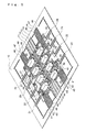
Fig. 1A is a perspective view showing a first embodiment of a matrix relay of the present invention, andFig. 1B a plan view showing an electrical wiring thereof; -
Fig. 2 is a perspective view showing a case where a housing of the matrix relay ofFig. 1A is removed; -
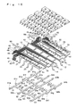
Fig. 3 is an exploded perspective view showing a case where the housing of the matrix relay ofFig 1A is removed; -
Fig. 4 is a perspective view showing a surface of a lead frame of the first embodiment; -
Fig. 5 is a perspective view of the surface of the lead frame showing a state in which opening/closing elements are mounted; -
Fig. 6 is a perspective view showing a rear surface of the lead frame of the first embodiment; -
Fig. 7 is a perspective view of the rear surface of the lead frame showing a state in which opening/closing elements are mounted; -
Fig. 8 is a perspective view showing a second embodiment of the matrix relay of the present invention; -
Fig. 9 is a perspective view showing a case where a housing of the matrix relay shown inFig. 8 is removed; -
Fig. 10 is an exploded perspective view showing a case where the housing of the matrix relay shown inFig. 8 is removed; -
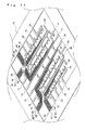
Fig. 11 is a perspective view showing a surface of a lead frame of the second embodiment; -
Fig. 12 is a perspective view of the surface of the lead frame showing a state in which opening/closing elements are mounted; and -
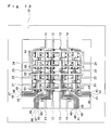
Fig. 13 is a plan view showing a rear surface of the lead frame of the second embodiment. -
- 1: matrix relay
- 2: housing
- 10: lead frame
- 11-14: row leads
- 21-24: column leads
- 25, 26: relay leads
- 27-29: jumper lines
- 40-49: control leads
- 51-54: opening/closing elements
- 61-64: opening/closing elements
- 71-74: opening/closing elements
- 81-84: opening/closing elements
- 90: jumper lines
- 91-94: jumper lines
- 91a-91h: die pads
- 92a-92h: die pads
- 93a-93h: die pads
- 94a-94h: die pads
- Embodiments of the present invention will be described with reference to the accompanying drawings of
Figs. 1 to 13 .
As shown inFigs. 1 to 7 , a first embodiment is a matrix relay 1 wherein opening/closing elements 51-54, 61-64 are mounted on a surface of alead frame 10, and opening/closing elements 71-74, 81-84 are mounted on a rear surface thereof, which are encapsulated with a resin. - As shown in
Fig. 4 , thelead frame 10, which is obtained by press working a band-shaped conductive sheet, consists of row leads 11-14 for forming rows, column leads 21-24 for forming columns, and control leads 41-45, 46-49 for inputting control signals. - In the row leads 11-14, die pads are extended at a predetermined pitch in order to mount the opening/closing elements 51-54 and the like.
- The column leads 21, 22, 23, 24, which are outer leads protruding from a housing 2 of the matrix relay 1, are electrically connected through relay leads 25, 26 and
jumper lines lead frame 10. It is a matter of course that the column leads 21-24 are insulated from the row leads 11-14 with an encapsulating resin material. - Since the relay leads 25, 26 are formed simultaneously with the row leads 11-14 and the like in the
lead frame 10 by press working, there is an advantage that the number of components to be inventory-controlled does not increase. - The jumper lines 27-29, which are press working products, electrically connect the column leads 21-24 on one side serving as outer leads to the column leads 21-24 on the other side through the relay leads 25, 26.
- The control leads 41-45, 46-49 are for, for example, applying voltages as control signals to the opening/closing elements 51-54 and the like described below and exciting electromagnetic coils incorporated therein, and driving movable iron pieces so that contacts are opened/closed. However, in the
lead frame 10 of the present embodiment, some terminals serve as dummy terminals so as to cope with other matrix relays with different numbers of contact circuits. - It is sufficient if the opening/closing elements 51-54, 61-64, 71-74, 81-84 can open/close circuits based on the control signals, and a MOSFET, an electromagnetic relay wherein a movable iron piece is driven by an electromagnetic force to open/close a contact or an electrostatic relay wherein a movable iron piece is driven by an electrostatic attraction force to open/close a circuit is exemplified. In the present embodiment, as the opening/closing elements 51-54, 61-64, 71-74, 81-84, those elements having terminals protruding from a bottom surface and bent outward are disclosed. However, the opening/closing elements are not limited to those elements in the above embodiment, and they may have terminals protruding from side surfaces and bent to a lower side or spherical terminals protruding from the bottom surface.
- Next, a method for manufacturing the matrix relay will be described.
First, as shown inFig. 4 , a cream solder is applied to predetermined positions of the surface of thelead frame 10 formed by punching through the band-shaped conductive sheet, and the jumper lines 27, 28, 29 and the opening/closing elements 51-54, 61-64 are respectively placed thereon, which are then passed through a heating furnace so as to be electrically connected. - Subsequently, the cream solder is applied to predetermined position of the rear surface of the
lead frame 10, and the opening/closing elements 71-54, 81-84 are respectively placed thereon, which are then passed through the heating furnace so as to be electrically connected. - Then, after removing unnecessary connection portions for supporting the relay leads 25, 26 and the like, outer perimeter edges of the front and rear surfaces of the
lead frame 10 are clamped from upper and lower sides by an integral mold not shown so that a cavity is formed. Thereafter, an encapsulation resin is injected into the cavity so as to be solidified, whereby the housing 2 is formed. - Further, the row leads 11-14, the column leads 21-24 and the control leads 41-49 that protrude from the housing 2 of the resin-encapsulated
lead frame 10 are cut and bent to the lower side, whereby the matrix relay 1 shown inFig. 1A is obtained. - According to the present embodiment, since the opening/closing elements 51-54, 61-64, and the opening/closing elements 71-74, 81-84 are placed on the front and rear surfaces of the
lead frame 10, respectively, the matrix relay 1 having a small floor area and a high mounting density is obtained.
Further, in the present embodiment, the column leads 21-24 are connected through the jumper lines 27, 28, 29, whereby the order of the row leads 11-14 and the column leads 21-24 is not replaced. Therefore, an input signal terminal and an output signal terminal regularly correspond to each other. This has an advantage that it is easy to instantaneously find out a connection state and that it is easy to use. - In the present embodiment, by transmitting control signals to the control terminals 41-49 and driving the opening/closing elements 51-54, 61-64, 71-74, 81-84 so that circuits are switched over, the matrix relay 1 which is capable of outputting signals inputted to the row leads 11-14 and the column leads 21-24 from desired positions selected.
- As shown in
Figs. 8 to 13 , a second embodiment is a case where opening/closing elements 51-54, 61-64, 71-74, 81-84 are placed in a grid form only on a surface of alead frame 10. - As shown in
Fig. 11 , thelead frame 10, which is obtained by press working a band-shaped conductive sheet, consists of row leads 11-14 for forming rows, column leads 21-24 for forming columns, and control leads 40-49 for inputting control signals. - Of the row leads 11-14, the row leads 11 and 14 are electrically connected through
jumper lines Fig. 10 . - The column leads 21-24, which are outer leads protruding from a housing 2 of the matrix relay 1, are respectively electrically connected through jumper lines 91-94 described below, which are placed on a rear side of the
lead frame 10. It is a matter of course that the column leads 21-24 are insulated from the row leads 11-14 with an encapsulating resin material. - The jumper lines 91-94 are each obtained by press working a bar-shaped conductive material to provide it with steps. For example, as shown in
Fig. 10 , diepads 94a-94h are formed on predetermined positions of thejumper line 94. - The control leads 40-44, and the control leads 45-49 are leads, for example, for applying voltages as control signals to the opening/closing elements 51-54, 61-64, 71-74, 81-84 and exciting electromagnetic coils incorporated therein, whereby movable iron pieces are driven so that contacts are opened/closed.
- It is sufficient if the opening/closing elements 51-54, 61-64, 71-74, 81-84 can open/close a circuit based on control signals, and they may not necessarily be the same as those of the first embodiment.
In the present embodiment, there are six terminals in total that are protruded, each three of which terminals are protruded from each of opposite side surfaces of each of the opening/closing elements 51-54, 61-64, 71-74, 81-84. One of two terminals that are connected to the same control lead is a dummy. One of two terminals that are positioned on the opposite side and connected to the same jumper line is a dummy. This is for stabilizing mounting of the opening/closing elements and also for coping with a case where opening/closing elements of different types are mounted. - Next, a method for manufacturing the matrix relay will be described.
First, as shown inFig. 11 , a cream solder is applied to predetermined positions of the surface of thelead frame 10 formed by punching through the band-shaped conductive sheet, and the jumper lines 90, 90 are placed thereon, which are then passed through the heating furnace so as to be electrically connected. Further, the die pads provided on both end portions of the jumper lines 91-94, for example thedie pads jumper line 94 are placed level on end portions of the column leads 24, 24 and soldered to be connected. The cream solder is applied to predetermined positions of thelead frame 10, and the opening/closing elements 51-54, 61-64, 71-74, 81-84 are respectively placed thereon, which are then passed through the heating furnace so as to be electrically connected. - Subsequently, outer perimeter edges of the front and rear surfaces of the
lead frame 10 are clamped from upper and lower sides by the integral mold not shown so that a cavity is formed. Thereafter, an encapsulation resin is injected into the cavity so as to be solidified, whereby the entirety is encapsulated. - Further, the row leads 11-14, the column leads 21-24 and the control leads 40-49 that protrude from the housing 2 of the resin-encapsulated
lead frame 10 are cut and bent to the lower side, whereby the matrix relay 1 shown inFig. 8A is obtained. - According to the present embodiment, since a working process of cutting unnecessary portions of the
lead frame 10 is not required during the manufacturing process unlike the first embodiment, there is an advantage of being highly productive. - In the present embodiment, by transmitting control signals to the control terminals 40-49 and driving the opening/closing elements 51-54, 61-64, 71-74, 81-84 so that the circuits are switched over, the matrix relay 1 which is capable of selecting signals inputted to the row leads 11-14, the column leads 21-24 and outputting signals from desired positions is obtained.
- Although the matrix relay wherein 4X4 opening/closing elements are disposed was described in the above embodiments, for example, it may be formed by disposing 1X5 opening/closing elements or disposing 3X6 opening/closing elements. It goes without saying that this may be changed as required.
- The matrix relay according to the present invention can be applied not only to the above embodiments but also to other forms of matrix relays.
Claims (3)
- A matrix relay wherein row leads of a lead frame, which are wired so that a plurality of input terminals and a plurality of output terminals are disposed respectively at opposite both sides, column leads of the lead frame, which are wired so that a plurality of input terminals and a plurality of output terminals are disposed respectively at both sides adjacent both the opposite sides, and a plurality of opening/closing elements, which are respectively connected to the row leads and the column leads, are encapsulated with a resin in a square housing; wherein
at least one of the row leads and the column leads is formed through at least one jumper line. - The matrix relay according to claim 1, wherein an intermediate region of each of the row leads or each of the column leads is formed of a relay lead disposed in the lead frame and the jumper line.
- The matrix relay according to claim 1 or 2, wherein the jumper line is obtained by providing a bar-shaped conductive wire with steps on each of which a die pad is provided protrusively.
Applications Claiming Priority (2)
| Application Number | Priority Date | Filing Date | Title |
|---|---|---|---|
| JP2006069427A JP2007250262A (en) | 2006-03-14 | 2006-03-14 | Matrix relay |
| PCT/JP2007/054826 WO2007105686A1 (en) | 2006-03-14 | 2007-03-12 | Matrix relay |
Publications (1)
| Publication Number | Publication Date |
|---|---|
| EP1998353A1 true EP1998353A1 (en) | 2008-12-03 |
Family
ID=38509506
Family Applications (1)
| Application Number | Title | Priority Date | Filing Date |
|---|---|---|---|
| EP07738298A Withdrawn EP1998353A1 (en) | 2006-03-14 | 2007-03-12 | Matrix relay |
Country Status (5)
| Country | Link |
|---|---|
| US (1) | US20090016038A1 (en) |
| EP (1) | EP1998353A1 (en) |
| JP (1) | JP2007250262A (en) |
| CN (1) | CN101401180A (en) |
| WO (1) | WO2007105686A1 (en) |
Families Citing this family (2)
| Publication number | Priority date | Publication date | Assignee | Title |
|---|---|---|---|---|
| TWI392065B (en) * | 2009-06-08 | 2013-04-01 | 乾坤科技股份有限公司 | Electronic component packaging module |
| CN114870531B (en) * | 2022-05-07 | 2023-09-29 | 西安热工研究院有限公司 | A control circuit for the pulse valve of a bag dust collector |
Family Cites Families (8)
| Publication number | Priority date | Publication date | Assignee | Title |
|---|---|---|---|---|
| JPH0581960U (en) * | 1992-03-31 | 1993-11-05 | ミツミ電機株式会社 | Jumper chip |
| JP3575707B2 (en) | 1995-03-13 | 2004-10-13 | 松下電工株式会社 | Matrix relay |
| JPH0982199A (en) * | 1995-09-11 | 1997-03-28 | Omron Corp | relay |
| KR100303576B1 (en) * | 1995-10-20 | 2001-09-29 | 타테이시 요시오 | Relay and matrix relay |
| JP3493446B2 (en) * | 1996-07-31 | 2004-02-03 | オムロン株式会社 | Matrix switch |
| JP2000012767A (en) * | 1998-06-18 | 2000-01-14 | Tokai Rika Co Ltd | Control IC and power window device |
| JP2001007565A (en) * | 1999-06-25 | 2001-01-12 | Matsushita Electric Works Ltd | Semiconductor relay device |
| JP2008294278A (en) * | 2007-05-25 | 2008-12-04 | Fujitsu Microelectronics Ltd | Semiconductor device, lead frame, and mounting structure of semiconductor device |
-
2006
- 2006-03-14 JP JP2006069427A patent/JP2007250262A/en active Pending
-
2007
- 2007-03-12 EP EP07738298A patent/EP1998353A1/en not_active Withdrawn
- 2007-03-12 CN CNA2007800088203A patent/CN101401180A/en active Pending
- 2007-03-12 WO PCT/JP2007/054826 patent/WO2007105686A1/en not_active Ceased
- 2007-03-12 US US12/280,653 patent/US20090016038A1/en not_active Abandoned
Non-Patent Citations (1)
| Title |
|---|
| See references of WO2007105686A1 * |
Also Published As
| Publication number | Publication date |
|---|---|
| WO2007105686A1 (en) | 2007-09-20 |
| CN101401180A (en) | 2009-04-01 |
| US20090016038A1 (en) | 2009-01-15 |
| JP2007250262A (en) | 2007-09-27 |
Similar Documents
| Publication | Publication Date | Title |
|---|---|---|
| US20100170706A1 (en) | Electronic module and method for manufacturing an electronic module | |
| EP2115774A2 (en) | Embedded inductor and method of producing thereof | |
| US6700074B2 (en) | Electrical component housing structures and their method of manufacture | |
| EP1772884B1 (en) | Electromagnetic relay | |
| JP5029536B2 (en) | Relay device | |
| US20090016038A1 (en) | Matrix relay | |
| JP4183010B2 (en) | Adapter board for insertion mounting type relay and surface mounting type relay using the same | |
| EP1885171A1 (en) | Package for electronic component, electronic component using such package, and method for producing package for electronic component | |
| JP6634748B2 (en) | Circuit components | |
| JP3977832B2 (en) | Circuit structure | |
| EP1119225A2 (en) | Circuit board, electrical connection box having the circuit board and method of making the circuit board | |
| US20060056648A1 (en) | Method for manufacturing a carrier element for a hearing aid and a carrier element for a hearing aid | |
| JP2016018821A (en) | Semiconductor device manufacturing method, semiconductor device, and lead frame | |
| KR100737135B1 (en) | Motor Control Electronic Control Unit of Vehicle | |
| US10421225B2 (en) | Method for manufacturing an arrangement comprising a housing part and at least two conductor paths | |
| JP2002134870A (en) | Circuit board for large current, manufacturing method thereof and composite circuit board | |
| JP2659316B2 (en) | Manufacturing method of leadless chip carrier | |
| JP2009152324A (en) | Manufacturing method of semiconductor device | |
| JP4737755B2 (en) | Electromagnetic relay | |
| JP2009135256A (en) | Semiconductor device and manufacturing method thereof | |
| JP5341389B2 (en) | Manufacturing method of resin-encapsulated semiconductor device | |
| JP2699163B2 (en) | Manufacturing method of pulse transformer | |
| US20040232526A1 (en) | Lead frame for stacked semiconductor packages, stacked semiconductor packages using it, and fabrication method thereof | |
| US20200066702A1 (en) | System in a package connectors | |
| JPH097492A (en) | Electronic fuse |
Legal Events
| Date | Code | Title | Description |
|---|---|---|---|
| PUAI | Public reference made under article 153(3) epc to a published international application that has entered the european phase |
Free format text: ORIGINAL CODE: 0009012 |
|
| 17P | Request for examination filed |
Effective date: 20081010 |
|
| AK | Designated contracting states |
Kind code of ref document: A1 Designated state(s): DE ES FR GB IT |
|
| STAA | Information on the status of an ep patent application or granted ep patent |
Free format text: STATUS: THE APPLICATION HAS BEEN WITHDRAWN |
|
| 18W | Application withdrawn |
Effective date: 20090121 |