EP1997688A2 - Einrichtung für Absorption der Kräfte bei Fahrzeugaufprall - Google Patents
Einrichtung für Absorption der Kräfte bei Fahrzeugaufprall Download PDFInfo
- Publication number
- EP1997688A2 EP1997688A2 EP08466011A EP08466011A EP1997688A2 EP 1997688 A2 EP1997688 A2 EP 1997688A2 EP 08466011 A EP08466011 A EP 08466011A EP 08466011 A EP08466011 A EP 08466011A EP 1997688 A2 EP1997688 A2 EP 1997688A2
- Authority
- EP
- European Patent Office
- Prior art keywords
- impact
- absorber
- forces
- vehicle
- deformation element
- Prior art date
- Legal status (The legal status is an assumption and is not a legal conclusion. Google has not performed a legal analysis and makes no representation as to the accuracy of the status listed.)
- Granted
Links
Images


Classifications
-
- B—PERFORMING OPERATIONS; TRANSPORTING
- B62—LAND VEHICLES FOR TRAVELLING OTHERWISE THAN ON RAILS
- B62D—MOTOR VEHICLES; TRAILERS
- B62D21/00—Understructures, i.e. chassis frame on which a vehicle body may be mounted
- B62D21/15—Understructures, i.e. chassis frame on which a vehicle body may be mounted having impact absorbing means, e.g. a frame designed to permanently or temporarily change shape or dimension upon impact with another body
-
- B—PERFORMING OPERATIONS; TRANSPORTING
- B60—VEHICLES IN GENERAL
- B60K—ARRANGEMENT OR MOUNTING OF PROPULSION UNITS OR OF TRANSMISSIONS IN VEHICLES; ARRANGEMENT OR MOUNTING OF PLURAL DIVERSE PRIME-MOVERS IN VEHICLES; AUXILIARY DRIVES FOR VEHICLES; INSTRUMENTATION OR DASHBOARDS FOR VEHICLES; ARRANGEMENTS IN CONNECTION WITH COOLING, AIR INTAKE, GAS EXHAUST OR FUEL SUPPLY OF PROPULSION UNITS IN VEHICLES
- B60K5/00—Arrangement or mounting of internal-combustion or jet-propulsion units
- B60K5/12—Arrangement of engine supports
Definitions
- the invention relates to a device for absorbing forces during vehicle impact.
- the prior art knows the solution when the vehicle is equipped with a deformation element for absorption of forces in the event of a vehicle collision.
- Deformation element is formed by rounded steel skid, which is connected to steel casting by screw. This assembly is then fastened by means of screws from below to the most rigid gear part, which is achieved in cooperation with the front axle of the required absorption of the forces. Disadvantage of this solution is high weight gain and complicated assembly.
- Cited disadvantages eliminates the device for absorbing the forces in vehicle impact, usually in the form of a forging, which is attached to the drive unit.
- the principle of the function of the device for absorbing the forces in the event of vehicle impact is that after a frontal collision of the vehicle comes into the obstacle to the movement of the unit and therefore also impact absorber against the direction of travel of the vehicle.
- the absorber is designed in such a way that it causes its impact on the axle beam, its subsequent deformation and therefore the desired absorption of the energy of the moving aggregate.
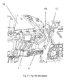
- Fig. 1 On the Fig. 1 is the impact absorber on the Fig. 2 the device for absorbing the forces at vehicle impact shown.
- Fig. 3 provides the impact absorber resp. Deformation element after impact of the vehicle.
- the device for absorption of forces in the event of vehicle impact is formed by impact absorber 1 , which is fastened to the drive unit 10 and contains the deformation element 5 .
- Fig. 1 On Fig. 1 the view is shown on impact absorber 1 from the side, which bears against the drive unit 10 , which is formed by flange 2 , connecting part 3, support member 4 and deformation element 5 .
- Fig. 2 represents the impact absorber 1 , which is attached to the drive unit 10 by means of flange 2 .
- the existing mounting points are exploited and the absorber 1 is fastened together with the torque arm 11 by two screws to the drive unit 10.
- the deformation element 5 has the shape of a quadrilateral with rounded corners and concave sides, being connected by a corner 100 " to the support part 4 and facing the axle support 12 with its opposite corner 100. It is designed so that, after impact of the absorber 1 in FIG Achstands the axle support 12 during movement of the unit 10 increasing resistance.
- the impact absorber 1 is designed in the form of an aluminum forgings.
- the support member 4 of the impact absorber 1 is provided with recesses 6 , 6 ', in which engages the ribbing of the drive unit 10 into it. This supports the effect of the caulking of the absorber 1 upon impact with the axle beam 12.
Landscapes
- Engineering & Computer Science (AREA)
- Chemical & Material Sciences (AREA)
- Combustion & Propulsion (AREA)
- Transportation (AREA)
- Mechanical Engineering (AREA)
- Vibration Dampers (AREA)
- Body Structure For Vehicles (AREA)
Abstract
Description
- Die Erfindung betrifft Einrichtung für Absorption der Kräfte bei Fahrzeugaufprall.
- Zurzeit ist vom Stand der Technik die Lösung bekannt, wann das Fahrzeug mit Deformationselement für Absorption der Kräfte bei Fahrzeugaufprall ausgerüstet ist. Deformationselement wird durch abgerundete Stahlkufe gebildet, die mit Stahlgussteil durch Schraube verbunden ist. Diese Baugruppe ist dann mittels Schrauben von unten zum starrsten Getriebeteil befestigt, wodurch unter Mitwirkung mit vorderem Achsträger der erforderlichen Absorption der Kräfte erzielt wird. Nachteil dieser Lösung ist hoher Gewichtszuwachs und komplizierte Montage.
- Angeführte Nachteile beseitigt die Einrichtung für Absorption der Kräfte bei Fahrzeugaufprall, meistens in Form eines Schmiedestücks, das zum Antriebsaggregat befestigt ist. Prinzip der Funktion der Einrichtung für Absorption der Kräfte bei Fahrzeugaufprall besteht darin, dass nach Frontalanprall des Fahrzeugs ins Hindernis zur Bewegung des Aggregats kommt und daher auch Aufprallabsorbers gegen Fahrtrichtung des Fahrzeugs. Der Absorber ist so konstruiert, dass bei dieser Bewegung zu dessen Aufprall in den Achsträger, dessen folgender Deformation und daher der gewünschten Absorption der Energie des sich bewegenden Aggregats kommt.
- Vorteil dieser Lösung ist niedrigeres Gewicht, einfache Montage auch in bestehenden Befestigungspunkten und Einbau.
- Auf der
Abb. 1 ist der Aufprallabsorber, auf derAbb. 2 die Einrichtung für Absorption der Kräfte bei Fahrzeugaufprall dargestellt.Abb. 3 stellt den Aufprallabsorber resp. Deformationselement nach Aufprall des Fahrzeugs dar. - Die Einrichtung für Absorption der Kräfte bei Fahrzeugaufprall wird durch Aufprallabsorber 1 gebildet, der zum Antriebsaggregat 10 befestigt ist und das Deformationselement 5 enthält.
- Auf
Abb. 1 ist die Ansicht auf Aufprallabsorber 1 von der Seite dargestellt, die zum Antriebsaggregat 10 anliegt, der durch Flansch 2, Verbindungsteil 3, Stützteil 4 und Deformationselement 5 gebildet ist. -
Abb. 2 stellt den Aufprallabsorber 1 dar, der zum Antriebsaggregat 10 mittels Flansches 2 befestigt ist. In günstiger Ausführung werden die bestehenden Montagepunkte ausgenutzt und der Absorber 1 ist zusammen mit Momentstrebe 11 durch zwei Schrauben zum Antriebsaggregat 10 befestigt. - Das Deformationselement 5 hat die Form eines Vierecks mit abgerundeten Ecken und konkaven Seiten, wobei durch eine Ecke 100" mit Stützteil 4 verbunden ist und mit gegenüberliegender Ecke 100 gegen den Achsträger 12 richtet. Es ist so konstruiert, dass es nach Aufprall des Absorbers 1 in den Achsträger 12 bei Bewegung des Aggregats 10 zunehmenden Widerstand leistet.
- Der Aufprallabsorber 1 ist in Form eines Aluminiumschmiedestücks ausgeführt.
- Der Stützteil 4 des Aufprallabsorbers 1 ist mit Ausnehmungen 6, 6' versehen, in welche die Verrippung des Antriebsaggregats 10 hinein greift. Dies unterstützt die Wirkung der Stemmung des Absorbers 1 beim Aufprall auf den Achsträger 12.
- Einrichtung für Absorption der Kräfte bei Fahrzeugaufprall nach der Erfindung kann in allen Landradfahrzeugen ausgenutzt werden.
-
- 1
- Aufprallabsorber
- 2
- Flansch
- 3
- Verbindungsteil
- 4
- Stützteil
- 5
- Deformationselement
- 6, 6'
- Ausnehmungen
- 10
- Antriebsaggregat
- 11
- Momentstrebe
- 12
- Achsträger
- 100, 100', 100", 100"'
- Ecken des Deformationselements
Claims (6)
- Einrichtung für Absorption der Kräfte bei Fahrzeugaufprall, gekennzeichnet dadurch, dass durch den Aufprallabsorber (1) gebildet ist, der zum Antriebsaggregat (10) befestigt ist und das Deformationselement (5) enthält.
- Einrichtung für Absorption der Kräfte bei Fahrzeugaufprall nach Anspruch 1, gekennzeichnet dadurch, dass der Aufprallabsorber (1) durch Flansch (2), Verbindungsteil (3), Stützteil (4) und Deformationselement (5) gebildet ist
- Einrichtung für Absorption der Kräfte bei Fahrzeugaufprall nach vorherigen Ansprüchen, gekennzeichnet dadurch, dass der Aufprallabsorber (1) zum Antriebsaggregat (10) mittels Flansches (2) befestigt ist.
- Einrichtung für Absorption der Kräfte bei Fahrzeugaufprall nach vorherigen Ansprüchen, gekennzeichnet dadurch, dass das Deformationselement (5) die Form eines Vierecks mit abgerundeten Ecken und konkaven Seiten, wobei durch eine Ecke (100") mit Stützteil (4) verbunden ist und mit gegenüberliegender Ecke (100) gegen den Achsträger (12) richtet.
- Einrichtung für Absorption der Kräfte bei Fahrzeugaufprall nach vorherigen Ansprüchen, gekennzeichnet dadurch, dass der Aufprallabsorber (1) in Form eines Aluminiumschmiedestücks ausgeführt ist.
- Einrichtung für Absorption der Kräfte bei Fahrzeugaufprall nach vorherigen Ansprüchen, gekennzeichnet dadurch, dass der Stützteil (4) des Aufprallabsorbers (1) mit Ausnehmungen (6, 6') versehen ist.
Applications Claiming Priority (1)
| Application Number | Priority Date | Filing Date | Title |
|---|---|---|---|
| CZ20070375A CZ2007375A3 (cs) | 2007-05-30 | 2007-05-30 | Zarízení k absorpci sil pri nárazu vozidla |
Publications (3)
| Publication Number | Publication Date |
|---|---|
| EP1997688A2 true EP1997688A2 (de) | 2008-12-03 |
| EP1997688A3 EP1997688A3 (de) | 2010-05-05 |
| EP1997688B1 EP1997688B1 (de) | 2012-01-04 |
Family
ID=39720373
Family Applications (1)
| Application Number | Title | Priority Date | Filing Date |
|---|---|---|---|
| EP08466011A Not-in-force EP1997688B1 (de) | 2007-05-30 | 2008-05-14 | Einrichtung für Absorption der Kräfte bei Fahrzeugaufprall |
Country Status (3)
| Country | Link |
|---|---|
| EP (1) | EP1997688B1 (de) |
| AT (1) | ATE539920T1 (de) |
| CZ (1) | CZ2007375A3 (de) |
Cited By (5)
| Publication number | Priority date | Publication date | Assignee | Title |
|---|---|---|---|---|
| FR2981620A1 (fr) * | 2011-10-19 | 2013-04-26 | Peugeot Citroen Automobiles Sa | Impacteur de choc pour groupe motopropulseur |
| WO2013072589A1 (fr) * | 2011-11-18 | 2013-05-23 | Peugeot Citroen Automobiles Sa | Dispositif de protection du moteur d'un véhicule automobile en cas de choc frontal |
| FR2990400A1 (fr) * | 2012-05-09 | 2013-11-15 | Peugeot Citroen Automobiles Sa | Impacteur de choc dynamique pour vehicule automobile |
| FR3013009A1 (fr) * | 2013-11-14 | 2015-05-15 | Peugeot Citroen Automobiles Sa | Impacteur avec fontionnement en traction pour un vehicule automobile |
| DE102016113197A1 (de) * | 2016-07-18 | 2018-01-18 | Dr. Ing. H.C. F. Porsche Aktiengesellschaft | Aufprallsicherung für ein Antriebsaggregat eines Fahrzeugs |
Family Cites Families (5)
| Publication number | Priority date | Publication date | Assignee | Title |
|---|---|---|---|---|
| DE3117378C2 (de) * | 1981-05-02 | 1986-10-23 | Dr.Ing.H.C. F. Porsche Ag, 7000 Stuttgart | Aufhängung für ein frontseitig, insbesondere querliegend angeordnetes Antriebsaggregat eines Kraftfahrzeugs |
| DE3710808A1 (de) * | 1987-03-31 | 1988-10-20 | Daimler Benz Ag | Abstuetzung von energieabsorbierend deformierten karosseriestrukturen an einem elastisch gelagerten frontmotor von kraftfahrzeugen |
| DE4313785C2 (de) * | 1993-04-27 | 1995-10-26 | Daimler Benz Ag | Kraftfahrzeug mit einer zwei Längsträger aufweisenden Tragstruktur |
| JP3698349B2 (ja) * | 1999-02-22 | 2005-09-21 | 本田技研工業株式会社 | 衝撃吸収ストッパ |
| US6276484B1 (en) * | 1999-09-30 | 2001-08-21 | Daimlerchrysler Corporation | Impact bar |
-
2007
- 2007-05-30 CZ CZ20070375A patent/CZ2007375A3/cs unknown
-
2008
- 2008-05-14 AT AT08466011T patent/ATE539920T1/de active
- 2008-05-14 EP EP08466011A patent/EP1997688B1/de not_active Not-in-force
Cited By (9)
| Publication number | Priority date | Publication date | Assignee | Title |
|---|---|---|---|---|
| FR2981620A1 (fr) * | 2011-10-19 | 2013-04-26 | Peugeot Citroen Automobiles Sa | Impacteur de choc pour groupe motopropulseur |
| WO2013072589A1 (fr) * | 2011-11-18 | 2013-05-23 | Peugeot Citroen Automobiles Sa | Dispositif de protection du moteur d'un véhicule automobile en cas de choc frontal |
| FR2982829A1 (fr) * | 2011-11-18 | 2013-05-24 | Peugeot Citroen Automobiles Sa | Dispositif de protection du moteur d'un vehicule automobile en cas de choc frontal |
| CN103998326A (zh) * | 2011-11-18 | 2014-08-20 | 标致·雪铁龙汽车公司 | 正面撞击时用于机动车辆发动机的保护装置 |
| RU2596387C2 (ru) * | 2011-11-18 | 2016-09-10 | Пежо Ситроен Отомобиль Са | Устройство защиты двигателя автотранспортного средства в случае лобового столкновения |
| CN103998326B (zh) * | 2011-11-18 | 2018-04-10 | 标致·雪铁龙汽车公司 | 正面撞击时用于机动车辆发动机的保护装置 |
| FR2990400A1 (fr) * | 2012-05-09 | 2013-11-15 | Peugeot Citroen Automobiles Sa | Impacteur de choc dynamique pour vehicule automobile |
| FR3013009A1 (fr) * | 2013-11-14 | 2015-05-15 | Peugeot Citroen Automobiles Sa | Impacteur avec fontionnement en traction pour un vehicule automobile |
| DE102016113197A1 (de) * | 2016-07-18 | 2018-01-18 | Dr. Ing. H.C. F. Porsche Aktiengesellschaft | Aufprallsicherung für ein Antriebsaggregat eines Fahrzeugs |
Also Published As
| Publication number | Publication date |
|---|---|
| EP1997688B1 (de) | 2012-01-04 |
| EP1997688A3 (de) | 2010-05-05 |
| ATE539920T1 (de) | 2012-01-15 |
| CZ2007375A3 (cs) | 2008-12-10 |
Similar Documents
| Publication | Publication Date | Title |
|---|---|---|
| EP1997688B1 (de) | Einrichtung für Absorption der Kräfte bei Fahrzeugaufprall | |
| EP3587221A1 (de) | Achsträger mit integrierter träger für einen antrieb | |
| DE202018103151U1 (de) | Aufhängungssystem mit lösbarer Verbindung | |
| DE102012101494B3 (de) | Lenksäule für ein Kraftfahrzeug mit einem Tragteil | |
| EP2931587B1 (de) | Kraftfahrzeug mit einem achsträger | |
| EP2754512B1 (de) | Fügevorrichtung und Verfahren zum vorlochfreien Fügen von Bauteilen mittels kraftimpulsbeaufschlagtem Fügeelement | |
| DE102004028161A1 (de) | Unterfahrschutz für Personenkraftfahrzeuge zur Anordnung unter Längsträgerniveau vor einem Hilfsrahmen oder Achsträger als zusätzliche Crashebene | |
| EP2231463B1 (de) | Lenksäulenanordnung für kraftfahrzeuge | |
| DE102018202795A1 (de) | Lenksäule für ein Kraftfahrzeug | |
| EP0252232B1 (de) | Haltevorrichtung für eine Lenksäule eines Kraftfahrzeugs | |
| EP1720746A1 (de) | Scheibenwischvorrichtung, insbesondere für ein kraftfahrzeug | |
| DE3544345A1 (de) | Kraftfahrzeuglenkung mit einer teleskoplenksaeule | |
| DE102015120013A1 (de) | Adaptive Stoßfängeranordnung | |
| DE102012111203B4 (de) | Struktur eines Fahrzeugunterrahmens | |
| DE102019129056A1 (de) | Aufhängungssystem mit lösbarer verbindung | |
| EP1306290A1 (de) | Frontpartie eines Kraftfahrzeugs | |
| EP2996908B1 (de) | Fahrzeug mit einem knickelement zwischen der grundkarosserie und einem aussenkarosserieteil | |
| DE102005049641A1 (de) | Aktives Scharnier einer Fahrzeughaube | |
| DE69403187T2 (de) | Vorderes Tragwerk für ein Kraftfahrzeug und Kraftfahrzeug mit diesem Tragwerk | |
| EP4259504B1 (de) | Halterungsschnittstelle und puffersystem für ein schienenfahrzeug | |
| DE102008022154A1 (de) | Vorrichtung zur aktiven Spurlenkung von Fahrzeugrädern | |
| DE4213101A1 (de) | Hinterachsaufhaengung fuer insbesondere autobusse | |
| DE2255963A1 (de) | Kraftfahrzeug | |
| DE102013019641A1 (de) | Fahrzeug | |
| DE102015210296A1 (de) | Crash-Vorrichtung für ein Kraftfahrzeug |
Legal Events
| Date | Code | Title | Description |
|---|---|---|---|
| PUAI | Public reference made under article 153(3) epc to a published international application that has entered the european phase |
Free format text: ORIGINAL CODE: 0009012 |
|
| AK | Designated contracting states |
Kind code of ref document: A2 Designated state(s): AT BE BG CH CY CZ DE DK EE ES FI FR GB GR HR HU IE IS IT LI LT LU LV MC MT NL NO PL PT RO SE SI SK TR |
|
| AX | Request for extension of the european patent |
Extension state: AL BA MK RS |
|
| PUAL | Search report despatched |
Free format text: ORIGINAL CODE: 0009013 |
|
| AK | Designated contracting states |
Kind code of ref document: A3 Designated state(s): AT BE BG CH CY CZ DE DK EE ES FI FR GB GR HR HU IE IS IT LI LT LU LV MC MT NL NO PL PT RO SE SI SK TR |
|
| AX | Request for extension of the european patent |
Extension state: AL BA MK RS |
|
| RIC1 | Information provided on ipc code assigned before grant |
Ipc: B60K 5/12 20060101ALI20100330BHEP Ipc: B60R 19/00 20060101AFI20080909BHEP |
|
| 17P | Request for examination filed |
Effective date: 20101105 |
|
| 17Q | First examination report despatched |
Effective date: 20101126 |
|
| AKX | Designation fees paid |
Designated state(s): AT BE BG CH CY CZ DE DK EE ES FI FR GB GR HR HU IE IS IT LI LT LU LV MC MT NL NO PL PT RO SE SI SK TR |
|
| RIC1 | Information provided on ipc code assigned before grant |
Ipc: B60K 5/12 20060101ALI20110608BHEP Ipc: B60R 19/00 20060101AFI20110608BHEP |
|
| GRAP | Despatch of communication of intention to grant a patent |
Free format text: ORIGINAL CODE: EPIDOSNIGR1 |
|
| GRAS | Grant fee paid |
Free format text: ORIGINAL CODE: EPIDOSNIGR3 |
|
| GRAA | (expected) grant |
Free format text: ORIGINAL CODE: 0009210 |
|
| AK | Designated contracting states |
Kind code of ref document: B1 Designated state(s): AT BE BG CH CY CZ DE DK EE ES FI FR GB GR HR HU IE IS IT LI LT LU LV MC MT NL NO PL PT RO SE SI SK TR |
|
| REG | Reference to a national code |
Ref country code: GB Ref legal event code: FG4D Free format text: NOT ENGLISH |
|
| REG | Reference to a national code |
Ref country code: CH Ref legal event code: EP |
|
| REG | Reference to a national code |
Ref country code: AT Ref legal event code: REF Ref document number: 539920 Country of ref document: AT Kind code of ref document: T Effective date: 20120115 |
|
| REG | Reference to a national code |
Ref country code: IE Ref legal event code: FG4D |
|
| REG | Reference to a national code |
Ref country code: DE Ref legal event code: R096 Ref document number: 502008006045 Country of ref document: DE Effective date: 20120308 |
|
| REG | Reference to a national code |
Ref country code: NL Ref legal event code: VDEP Effective date: 20120104 |
|
| PG25 | Lapsed in a contracting state [announced via postgrant information from national office to epo] |
Ref country code: SI Free format text: LAPSE BECAUSE OF FAILURE TO SUBMIT A TRANSLATION OF THE DESCRIPTION OR TO PAY THE FEE WITHIN THE PRESCRIBED TIME-LIMIT Effective date: 20120104 |
|
| LTIE | Lt: invalidation of european patent or patent extension |
Effective date: 20120104 |
|
| PG25 | Lapsed in a contracting state [announced via postgrant information from national office to epo] |
Ref country code: HR Free format text: LAPSE BECAUSE OF FAILURE TO SUBMIT A TRANSLATION OF THE DESCRIPTION OR TO PAY THE FEE WITHIN THE PRESCRIBED TIME-LIMIT Effective date: 20120104 Ref country code: LT Free format text: LAPSE BECAUSE OF FAILURE TO SUBMIT A TRANSLATION OF THE DESCRIPTION OR TO PAY THE FEE WITHIN THE PRESCRIBED TIME-LIMIT Effective date: 20120104 Ref country code: NO Free format text: LAPSE BECAUSE OF FAILURE TO SUBMIT A TRANSLATION OF THE DESCRIPTION OR TO PAY THE FEE WITHIN THE PRESCRIBED TIME-LIMIT Effective date: 20120404 Ref country code: BG Free format text: LAPSE BECAUSE OF FAILURE TO SUBMIT A TRANSLATION OF THE DESCRIPTION OR TO PAY THE FEE WITHIN THE PRESCRIBED TIME-LIMIT Effective date: 20120404 Ref country code: IS Free format text: LAPSE BECAUSE OF FAILURE TO SUBMIT A TRANSLATION OF THE DESCRIPTION OR TO PAY THE FEE WITHIN THE PRESCRIBED TIME-LIMIT Effective date: 20120504 Ref country code: NL Free format text: LAPSE BECAUSE OF FAILURE TO SUBMIT A TRANSLATION OF THE DESCRIPTION OR TO PAY THE FEE WITHIN THE PRESCRIBED TIME-LIMIT Effective date: 20120104 |
|
| REG | Reference to a national code |
Ref country code: IE Ref legal event code: FD4D |
|
| PG25 | Lapsed in a contracting state [announced via postgrant information from national office to epo] |
Ref country code: PT Free format text: LAPSE BECAUSE OF FAILURE TO SUBMIT A TRANSLATION OF THE DESCRIPTION OR TO PAY THE FEE WITHIN THE PRESCRIBED TIME-LIMIT Effective date: 20120504 Ref country code: GR Free format text: LAPSE BECAUSE OF FAILURE TO SUBMIT A TRANSLATION OF THE DESCRIPTION OR TO PAY THE FEE WITHIN THE PRESCRIBED TIME-LIMIT Effective date: 20120405 Ref country code: FI Free format text: LAPSE BECAUSE OF FAILURE TO SUBMIT A TRANSLATION OF THE DESCRIPTION OR TO PAY THE FEE WITHIN THE PRESCRIBED TIME-LIMIT Effective date: 20120104 Ref country code: PL Free format text: LAPSE BECAUSE OF FAILURE TO SUBMIT A TRANSLATION OF THE DESCRIPTION OR TO PAY THE FEE WITHIN THE PRESCRIBED TIME-LIMIT Effective date: 20120104 Ref country code: LV Free format text: LAPSE BECAUSE OF FAILURE TO SUBMIT A TRANSLATION OF THE DESCRIPTION OR TO PAY THE FEE WITHIN THE PRESCRIBED TIME-LIMIT Effective date: 20120104 |
|
| PG25 | Lapsed in a contracting state [announced via postgrant information from national office to epo] |
Ref country code: CY Free format text: LAPSE BECAUSE OF FAILURE TO SUBMIT A TRANSLATION OF THE DESCRIPTION OR TO PAY THE FEE WITHIN THE PRESCRIBED TIME-LIMIT Effective date: 20120104 |
|
| PG25 | Lapsed in a contracting state [announced via postgrant information from national office to epo] |
Ref country code: RO Free format text: LAPSE BECAUSE OF FAILURE TO SUBMIT A TRANSLATION OF THE DESCRIPTION OR TO PAY THE FEE WITHIN THE PRESCRIBED TIME-LIMIT Effective date: 20120104 Ref country code: SE Free format text: LAPSE BECAUSE OF FAILURE TO SUBMIT A TRANSLATION OF THE DESCRIPTION OR TO PAY THE FEE WITHIN THE PRESCRIBED TIME-LIMIT Effective date: 20120104 Ref country code: IE Free format text: LAPSE BECAUSE OF FAILURE TO SUBMIT A TRANSLATION OF THE DESCRIPTION OR TO PAY THE FEE WITHIN THE PRESCRIBED TIME-LIMIT Effective date: 20120104 Ref country code: DK Free format text: LAPSE BECAUSE OF FAILURE TO SUBMIT A TRANSLATION OF THE DESCRIPTION OR TO PAY THE FEE WITHIN THE PRESCRIBED TIME-LIMIT Effective date: 20120104 Ref country code: EE Free format text: LAPSE BECAUSE OF FAILURE TO SUBMIT A TRANSLATION OF THE DESCRIPTION OR TO PAY THE FEE WITHIN THE PRESCRIBED TIME-LIMIT Effective date: 20120104 |
|
| PLBE | No opposition filed within time limit |
Free format text: ORIGINAL CODE: 0009261 |
|
| STAA | Information on the status of an ep patent application or granted ep patent |
Free format text: STATUS: NO OPPOSITION FILED WITHIN TIME LIMIT |
|
| BERE | Be: lapsed |
Owner name: SKODA AUTO A.S. Effective date: 20120531 |
|
| PG25 | Lapsed in a contracting state [announced via postgrant information from national office to epo] |
Ref country code: SK Free format text: LAPSE BECAUSE OF FAILURE TO SUBMIT A TRANSLATION OF THE DESCRIPTION OR TO PAY THE FEE WITHIN THE PRESCRIBED TIME-LIMIT Effective date: 20120104 |
|
| 26N | No opposition filed |
Effective date: 20121005 |
|
| PG25 | Lapsed in a contracting state [announced via postgrant information from national office to epo] |
Ref country code: MC Free format text: LAPSE BECAUSE OF NON-PAYMENT OF DUE FEES Effective date: 20120531 |
|
| REG | Reference to a national code |
Ref country code: CH Ref legal event code: PL |
|
| PG25 | Lapsed in a contracting state [announced via postgrant information from national office to epo] |
Ref country code: CH Free format text: LAPSE BECAUSE OF NON-PAYMENT OF DUE FEES Effective date: 20120531 Ref country code: LI Free format text: LAPSE BECAUSE OF NON-PAYMENT OF DUE FEES Effective date: 20120531 |
|
| REG | Reference to a national code |
Ref country code: DE Ref legal event code: R097 Ref document number: 502008006045 Country of ref document: DE Effective date: 20121005 |
|
| PG25 | Lapsed in a contracting state [announced via postgrant information from national office to epo] |
Ref country code: BE Free format text: LAPSE BECAUSE OF NON-PAYMENT OF DUE FEES Effective date: 20120531 |
|
| PG25 | Lapsed in a contracting state [announced via postgrant information from national office to epo] |
Ref country code: ES Free format text: LAPSE BECAUSE OF FAILURE TO SUBMIT A TRANSLATION OF THE DESCRIPTION OR TO PAY THE FEE WITHIN THE PRESCRIBED TIME-LIMIT Effective date: 20120415 |
|
| PG25 | Lapsed in a contracting state [announced via postgrant information from national office to epo] |
Ref country code: MT Free format text: LAPSE BECAUSE OF FAILURE TO SUBMIT A TRANSLATION OF THE DESCRIPTION OR TO PAY THE FEE WITHIN THE PRESCRIBED TIME-LIMIT Effective date: 20120104 |
|
| PGFP | Annual fee paid to national office [announced via postgrant information from national office to epo] |
Ref country code: DE Payment date: 20130522 Year of fee payment: 6 Ref country code: GB Payment date: 20130522 Year of fee payment: 6 |
|
| PGFP | Annual fee paid to national office [announced via postgrant information from national office to epo] |
Ref country code: FR Payment date: 20130604 Year of fee payment: 6 Ref country code: IT Payment date: 20130525 Year of fee payment: 6 |
|
| PG25 | Lapsed in a contracting state [announced via postgrant information from national office to epo] |
Ref country code: TR Free format text: LAPSE BECAUSE OF FAILURE TO SUBMIT A TRANSLATION OF THE DESCRIPTION OR TO PAY THE FEE WITHIN THE PRESCRIBED TIME-LIMIT Effective date: 20120104 |
|
| PG25 | Lapsed in a contracting state [announced via postgrant information from national office to epo] |
Ref country code: LU Free format text: LAPSE BECAUSE OF NON-PAYMENT OF DUE FEES Effective date: 20120514 |
|
| REG | Reference to a national code |
Ref country code: AT Ref legal event code: MM01 Ref document number: 539920 Country of ref document: AT Kind code of ref document: T Effective date: 20130514 |
|
| PG25 | Lapsed in a contracting state [announced via postgrant information from national office to epo] |
Ref country code: HU Free format text: LAPSE BECAUSE OF FAILURE TO SUBMIT A TRANSLATION OF THE DESCRIPTION OR TO PAY THE FEE WITHIN THE PRESCRIBED TIME-LIMIT Effective date: 20080514 |
|
| PG25 | Lapsed in a contracting state [announced via postgrant information from national office to epo] |
Ref country code: AT Free format text: LAPSE BECAUSE OF NON-PAYMENT OF DUE FEES Effective date: 20130514 |
|
| REG | Reference to a national code |
Ref country code: DE Ref legal event code: R119 Ref document number: 502008006045 Country of ref document: DE |
|
| GBPC | Gb: european patent ceased through non-payment of renewal fee |
Effective date: 20140514 |
|
| REG | Reference to a national code |
Ref country code: FR Ref legal event code: ST Effective date: 20150130 |
|
| REG | Reference to a national code |
Ref country code: DE Ref legal event code: R119 Ref document number: 502008006045 Country of ref document: DE Effective date: 20141202 |
|
| PG25 | Lapsed in a contracting state [announced via postgrant information from national office to epo] |
Ref country code: DE Free format text: LAPSE BECAUSE OF NON-PAYMENT OF DUE FEES Effective date: 20141202 Ref country code: IT Free format text: LAPSE BECAUSE OF NON-PAYMENT OF DUE FEES Effective date: 20140514 |
|
| PG25 | Lapsed in a contracting state [announced via postgrant information from national office to epo] |
Ref country code: GB Free format text: LAPSE BECAUSE OF NON-PAYMENT OF DUE FEES Effective date: 20140514 Ref country code: FR Free format text: LAPSE BECAUSE OF NON-PAYMENT OF DUE FEES Effective date: 20140602 |
|
| PGFP | Annual fee paid to national office [announced via postgrant information from national office to epo] |
Ref country code: CZ Payment date: 20201126 Year of fee payment: 14 |
|
| PG25 | Lapsed in a contracting state [announced via postgrant information from national office to epo] |
Ref country code: CZ Free format text: LAPSE BECAUSE OF NON-PAYMENT OF DUE FEES Effective date: 20220514 |