EP1997683A2 - Vehicle outside mirror device - Google Patents
Vehicle outside mirror device Download PDFInfo
- Publication number
- EP1997683A2 EP1997683A2 EP08009735A EP08009735A EP1997683A2 EP 1997683 A2 EP1997683 A2 EP 1997683A2 EP 08009735 A EP08009735 A EP 08009735A EP 08009735 A EP08009735 A EP 08009735A EP 1997683 A2 EP1997683 A2 EP 1997683A2
- Authority
- EP
- European Patent Office
- Prior art keywords
- clutch
- shaft
- gear
- holder
- mirror assembly
- Prior art date
- Legal status (The legal status is an assumption and is not a legal conclusion. Google has not performed a legal analysis and makes no representation as to the accuracy of the status listed.)
- Granted
Links
- 238000003780 insertion Methods 0.000 description 6
- 230000037431 insertion Effects 0.000 description 6
- 230000001105 regulatory effect Effects 0.000 description 6
- 238000010586 diagram Methods 0.000 description 4
- 239000002184 metal Substances 0.000 description 3
- 239000000758 substrate Substances 0.000 description 3
- 238000005516 engineering process Methods 0.000 description 2
- 239000011347 resin Substances 0.000 description 2
- 229920005989 resin Polymers 0.000 description 2
- 239000004677 Nylon Substances 0.000 description 1
- 239000000853 adhesive Substances 0.000 description 1
- 230000001070 adhesive effect Effects 0.000 description 1
- 230000005540 biological transmission Effects 0.000 description 1
- 239000000872 buffer Substances 0.000 description 1
- 238000010276 construction Methods 0.000 description 1
- 230000000694 effects Effects 0.000 description 1
- 238000012986 modification Methods 0.000 description 1
- 230000004048 modification Effects 0.000 description 1
- 229920001778 nylon Polymers 0.000 description 1
Images


Classifications
-
- B—PERFORMING OPERATIONS; TRANSPORTING
- B60—VEHICLES IN GENERAL
- B60R—VEHICLES, VEHICLE FITTINGS, OR VEHICLE PARTS, NOT OTHERWISE PROVIDED FOR
- B60R1/00—Optical viewing arrangements; Real-time viewing arrangements for drivers or passengers using optical image capturing systems, e.g. cameras or video systems specially adapted for use in or on vehicles
- B60R1/02—Rear-view mirror arrangements
- B60R1/06—Rear-view mirror arrangements mounted on vehicle exterior
- B60R1/062—Rear-view mirror arrangements mounted on vehicle exterior with remote control for adjusting position
- B60R1/07—Rear-view mirror arrangements mounted on vehicle exterior with remote control for adjusting position by electrically powered actuators
- B60R1/074—Rear-view mirror arrangements mounted on vehicle exterior with remote control for adjusting position by electrically powered actuators for retracting the mirror arrangements to a non-use position alongside the vehicle
Definitions
- the present invention relates to a vehicle outside mirror device.
- the conventional vehicle outside mirror device includes a mirror, a door mirror stay, and a mechanism including a casing, a motor assembly, a gear plate, and a clutch plate.
- the mirror assembly can be rotated automatically, by using the motor, or manually, by pushing with a hand. Specifically, when the motor is driven, the gear plate and the clutch plate engage with each other whereby the mirror assembly rotates. On the contrary, when the mirror assembly is pushed with a hand, the gear plate and the clutch plate disengage from each other whereby the mirror assembly rotates.
- the clutch plate is accommodated inside the gear plate.
- the gear plate must be made larger enough to accommodate the clutch plate. Such a configuration increases the size of the mechanism.
- a vehicle outside mirror device including a mirror assembly; an electronic unit; and a base configured to be attachable to a vehicle body.
- the electronic unit includes a shaft holder that is fixed to the base; a shaft that is fixed to the shaft holder; a casing that houses the mirror assembly and that is rotatably attached to the shaft; and a driving mechanism that is housed in the casing and that rotates the mirror assembly with respect to the shaft, the driving mechanism including a motor and a rotational force transmitting mechanism, the rotational force transmitting mechanism including a deceleration unit and a clutch unit.
- the clutch unit includes a clutch gear that is rotatably attached to the shaft, and that is a last gear in the deceleration unit; and a clutch holder that is attached to the shaft so as not to be rotatable.
- the clutch gear and the clutch holder are engaged with each other by an urging force.
- the clutch gear and the clutch holder are disengaged from each other when a force of a predetermined amount or more acts on the mirror assembly.
- the clutch gear has a first guide portion that is formed in an inner position with respect to an outer circumference of the clutch gear and the clutch holder has a second guide portion that is formed in an inner position with respect to an outer circumference of the clutch holder.
- the clutch gear and the clutch holder relatively move in a direction of an axis of the shaft by guiding along the first guide portion and the second guide portion.
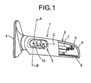
- FIG. 1 is a schematic diagram of the vehicle outside mirror device 1.
- the vehicle outside mirror device 1 is an electronic door mirror device, and it is for attaching to a right door (not shown) of a vehicle (not shown).
- a vehicle outside mirror device for attaching to a left door basically has the same structure as that of the vehicle outside mirror device 1 except that it is for a left hand application.
- the vehicle outside mirror device 1 includes a mirror assembly 2, an electronic unit 3, and a base 4 (mirror base).
- the base 4 is fixed to the right door.
- the mirror assembly 2 is held by the base 4 in such a manner that the mirror assembly 2 is rotatable with respect to the right door.
- the mirror assembly 2 includes a mirror housing 5, an attachment bracket 6, a power unit 7, and a mirror 8.
- the attachment bracket 6 is attached to an inner wall of the mirror housing 5.
- the power unit 7 is attached to the attachment bracket 6.
- the mirror 8 is movably attached to the power unit 7 so as to incline vertically and horizontally.
- the electronic unit 3 includes a shaft holder 9, a shaft 10, a gear case 11, a cover 12, a motor 13, a deceleration mechanism 14 as a torque transmission mechanism, a clutch mechanism 15, a plate 16, a fixation plate 17, and a substrate 27.
- the deceleration mechanism 14 is rotatably borne by the plate 16.
- the plate 16 and the deceleration mechanism 14 constitute a subassembly.
- the shaft holder 9 is fixed to the base 4.
- the shaft 10 is integral with the shaft holder 9.
- the shaft 10 is hollow, and harnesses 44 are passed though the shaft 10 (see Fig. 3 ).
- the gear case 11 and the cover 12 are rotatably attached to the shaft 10.
- the gear case 11 is attached to the attachment bracket 6.
- the motor 13, the deceleration mechanism 14, the clutch mechanism 15, and the plate 16 are housed in the gear case 11.
- the gear case 11 is made of, for example, resin such as nylon. As shown in Figs. 2 to 7 , a cross section of the gear case 11 has a concave shape, i.e., the gear case 11 has a closed portion on one side (bottom side) and an open portion on the other side (top side).
- the housing unit 18 having a cross section in a concave shape i.e., the housing unit 18 having a closed portion on a side of the shaft holder 9 and an open portion on a side of the cover 12, is provided in the gear case 11.
- a circular insertion hole 19 is formed on the closed side of the gear case 11. The shaft 10 is inserted into the insertion hole 19 such that the gear case 11 is rotatable on the shaft 10.
- a guide protruding portion 20 having an annular shape and that is concentric with the shaft 10 is provided integrally with an upper surface of the shaft holder 9.
- a stopper protruding portion 21 having an arc shape and that is concentric with the shaft 10 is provided integrally with an outer surface of the guide protruding portion 20.
- the stopper protruding portion 21 has stopper facets 22 on both ends. Only one of the stopper facets 22 is seen in Fig. 2 because the other stopper facet is behind the shaft 10.
- a guide groove 23 having an annular shape and the same center axis as that of the shaft 10 is formed in a bottom surface of the gear case 11.
- a guide groove 24 having an arc shape and that is concentric with the shaft 10 is formed in the bottom surface of the gear case 11 in an outer position with respect to an outer circumference of the guide groove 23.
- stopper facets 25 are formed in the gear case 11 at both boundaries between the guide groove 23 and the guide groove 24.
- the guide protruding portion 20 and the stopper protruding portion 21 are inserted into and fitted to the guide groove 23 and the guide groove 24.
- the guide groove 23, the guide groove 24, the guide protruding portion 20, and the stopper protruding portion 21 constitute a guide unit that guides the mirror assembly 2 to rotate with respect to the base 4.
- the stopper facets 22 of the stopper protruding portion 21 abut with the stopper facets 25 of the gear case 11.
- the mirror assembly 2 can not be rotated further when the stopper facets 22 abut with the stopper facets 25, which prevents hitting of the mirror assembly 2 with the vehicle body.
- the guide groove 23, the guide groove 24, the guide protruding portion 20, and the stopper protruding portion 21 constitute a stopper unit that prevents hitting of the mirror assembly 2 with the vehicle body.
- the cover 12 is made of resin.
- the cross section of the cover 12 has an inverted concave shape as shown in Figs. 2 , 3 , and 7 , i.e., the cover 12 has a closed portion on one (top) side and an open portion on the other (bottom) side.
- the housing unit 18 having a cross section in an inverted concave shape i.e., the housing unit 18 having a closed portion on one side and having an open portion on a side of the gear case 11, is provided to the cover 12.
- a harness insertion cylindrical portion 26 that communicates with the shaft 10 is integrally mounted to the cover 12.
- a periphery of the housing unit 18 of the gear case 11 and a periphery of the housing unit 18 of the cover 12 are engaged and fixed to each other.
- the gear case 11 and the cover 12 can be fixed to each other by adhering with an adhesive.
- the substrate 27 is attached to the plate 16.
- a switch circuit that controls (drives and stops) the motor 13 is mounted on the substrate 27.
- An insertion hole 39 that communicates with the harness insertion cylindrical portion 26 is formed in the cover 12.
- the shaft 10 is inserted into the insertion hole 39.
- the cover 12 and the gear case 11 are rotatably attached to the shaft 10.
- the deceleration mechanism 14 and the clutch mechanism 15 are positioned between an output shaft 28 of the motor 13 and the shaft 10, and the deceleration mechanism 14 and the clutch mechanism 15 transmit a rotational force of the motor 13 to the shaft 10.
- the motor 13, the deceleration mechanism 14, and the clutch mechanism 15 rotate the mirror assembly 2 with respect to the shaft 10.
- the deceleration mechanism 14 includes a first worm gear 29, i.e., a first gear, a helical gear 30, i.e., a second gear, and engages with the first worm gear 29, a second worm gear 31, i.e., a third gear, and a clutch gear 32, i.e., a last gear, and with which the second worm gear 31 is engaged.
- the first worm gear 29 is rotatably borne by the plate 16 via a pin 33.
- the first worm gear 29 is connected to the output shaft 28.
- the helical gear 30 is rotatably bored by the plate 16.
- the second worm gear 31 is integrally and rotatably engaged with the helical gear 30 and rotatably borne by the gear case 11.
- the clutch mechanism 15 includes the clutch gear 32 made of metal, a clutch holder 35 made of metal, a spring 36, a push nut 37, and a washer 38 made of metal.
- the washer 38, the clutch holder 35, the clutch gear 32, and the spring 36 are sequentially fitted to the shaft 10, and the push nut 37 is fixed to the shaft 10, so that the spring 36 is compressed by the push nut 37.
- the clutch gear 32 and the clutch holder 35 are engaged with each other such that they can be disengaged from each other.
- a rotational force of the motor 13 is transmitted to the shaft 10.
- the clutch gear 32 and the clutch holder 35 constitute a clutch mechanism.
- the clutch gear 32 is attached to the shaft 10 so as to be rotatable and movable in a direction of an axis (hereinafter, "axial direction") of the shaft 10.
- the clutch holder 35 is attached to the shaft 10 so as not to be rotatable and so as to be movable in the axial direction of the shaft 10.
- a plurality of, for example three, clutch protruding portions 40 are formed on a bottom surface of the clutch gear 32 and a plurality of, for example three, clutch recess portions 41 are formed in an upper surface of the clutch holder 35.
- the clutch protruding portions 40 are positioned at equal intervals on the bottom surface of the clutch gear 32 and the clutch recess portions 41 are positioned at equal intervals on the upper surface of the clutch holder 35.
- the clutch protruding portions 40 and the clutch recess portions 41 engage with each other.
- the clutch gear 32 and the clutch holder 35 are in an engaged state.
- a force (external force) of a predetermined amount or more is applied to the mirror assembly 2 with, for example, hand, the clutch protruding portions 40 and the clutch recess portions 41 disengage from each other (released).
- the clutch gear 32 and the clutch holder 35 disengaged from each other (released).
- Guide portions are formed in the clutch gear 32 in an inner position with respect to an outer circumference of the clutch gear 32 and in the clutch holder 35 in an inner position with respect to an outer circumference of the clutch holder 35.
- the guide portions guide the clutch gear 32 to move with respect to the clutch holder 35 in an axial direction thereof (i.e., with respect to the shaft 10 in the axial direction of the shaft 10).
- a guide protruding portion 42 that is cylindrical (or, in which at least one arc is provided) is integrally provided as a step to the upper surface of the clutch holder 35 in an inner position with respect to the outer circumference of the clutch holder 35.
- a guide hole 43 having a circular shape (or, in which at least one arc is formed) is formed in an inner position with respect to an outer circumference of the clutch gear 32.
- the guide protruding portion 42 is inserted into the guide hole 43 so as to be rotatable and movable in the axial direction of the shaft 10.
- the outer circumference of the guide protruding portion 42 and an inner circumference of the guide hole 43 contact with each other and the guide protruding portion 42 and the guide hole 43 guide the clutch gear 32 to move in the axial direction of the shaft 10.
- An outer diameter of the outer circumference of the guide protruding portion 42 and an inner diameter of an inner circumference of the guide hole 43 is equal or approximately equal to each other, i.e., or the outer diameter of the outer circumference of the guide protruding portion 42 is slightly larger than the inner diameter of the inner periphery of the guide hole 43.
- the clutch gear 32 is opposed to the spring 36 and the clutch holder 35 is opposed to the washer 38 and the gear case 11.
- the washer 38 is fixed to the gear case 11.
- the clutch holder 35 and the washer 38 include a rotation range regulating mechanism that regulates a range of automatic rotation of the mirror assembly 2 between the use position C and the storage position B.
- the mirror assembly 2 can be stopped at the storage position B not only because of the regulation by the automatic rotation range regulating mechanism but also because the stopper facets 25 of the gear case 11 make contact with the stopper facets 22 of the stopper protruding portion 21.
- the motor 13 When the driver of the vehicle operates a switch (not shown) provided inside the vehicle in a state that the mirror assembly 2 is in the use position C, the motor 13 generates a rotational force.
- the rotational force of the motor 13 is transmitted via the output shaft 28 and the deceleration mechanism 14 to the clutch gear 32 that is fixed to the shaft 10.
- the clutch protruding portions 40 of the clutch gear 32 and the clutch recess portions 41 of the clutch holder 35 are maintained engaged with each other.
- the clutch gear 32 is not rotatable on the shaft 10. Therefore, the second worm gear 31 rotates on the clutch gear 32, and thus, the mirror assembly 2 is rotated on the shaft 10.
- the mirror assembly 2 rotates from the use position C to the storage position B.
- a current supplied to the motor 13 increases as a result of regulation by the automatic rotation range regulating mechanism.
- the switch circuit operates to stop supply of the current to the motor 13.
- the mirror assembly 2 stops at the storage position B.
- the stopper facets 22 of the stopper protruding portion 21 make contact with the stopper facets 25 of the gear case 11. Therefore, the mirror assembly 2 can not rotate further, which prevents hitting of the mirror assembly 2 with the vehicle body.
- the mirror assembly 2 is automatically rotated from the storage position B to the use position C.
- the motor 13 When the driver operates the switch arranged inside the vehicle in a state that the mirror assembly is in the storage position B, the motor 13 generates a rotational force. Because of the rotational force of the motor 13, the gear case 11 rotates counterclockwise on the shaft 10, so that the mirror assembly 2 rotates counterclockwise from the storage position B.
- the current (operation current) supplied to the motor 13 increases as a result of regulation by the automatic rotation range regulating mechanism.
- the switch circuit operates to stop the supply of the current to the motor 13. As a result, the mirror assembly 2 stops at the storage position C.
- the driver pushes (or pulls) the mirror assembly 2 is a desired direction, i.e., the driver applies a force (external force) of a predetermined amount or more in a desired direction to the mirror assembly 2.
- a force external force
- an inclining surface of the clutch protruding portion 40 slips up on an inclining surface of the clutch recess portion 41. Therefore, the clutch gear 32 rotates and moves upward with respect to the clutch holder 35, which is not rotatable, in the axial direction of the shaft 10 against the urging force of the spring 36.
- the mirror assembly 2 rotates on the shaft 10. In this manner, the mirror assembly 2 is manually rotated clockwise from the use position C to the storage position B or counterclockwise from the storage unit B to the use position C.
- the clutch protruding portions 40 of the clutch gear 32 and the clutch recess portions 41 of the clutch holder 35 are engaged with each other by the urging force of the spring 36, i.e., the clutch gear 32 and the clutch holder 35 are engaged with each other.
- the driver pushes (or pulls) the mirror assembly 2 in the counterclockwise direction.
- the clutch protruding portions 40 of the clutch gear 32 and the clutch recess portions 41 of the clutch holder 35 are maintained engaged with each other, i.e., the clutch gear 32 and the clutch holder 35 are maintained engaged with each other. Therefore, the clutch gear 32 and the clutch holder 35 move upwards against the urging force of the spring 36.
- the automatic rotation range regulating mechanism does not regulate the rotation of the mirror assembly 2.
- the mirror assembly 2 is rotated counterclockwise from the use position C to the forward inclination position A.
- the stopper facets 22 of the stopper protruding portion 21 abut with the stopper facets 25 of the gear case 11. Therefore, the rotation of the mirror assembly 2 can not be rotated further, which prevents hitting of the mirror assembly 2 with the vehicle body.
- the driver pushes (or pulls) the mirror assembly 2 in the clockwise direction.
- the gear case 11 attached to the mirror assembly 2 rotates clockwise. Therefore, the mirror assembly 2 rotates clockwise from the forward inclination position A to the use position C.
- the clutch gear 32 and the clutch holder 35 move downward as shown in Fig. 3 because of the urging force of the spring 36.
- the mirror assembly 2 stops at the use position C because of the regulation by the automatic rotation range regulating mechanism.
- the mirror assembly 2 When a load of a predetermined amount or more is undesirably applied to the mirror assembly 2, clockwise or counterclockwise, the mirror assembly 2 rotates between the use position C and the storage position B or between the use position C and the forward inclination position A. Such motion buffers the applied force and prevents damage of the vehicle external mirror device 1.
- the clutch gear 32 and the clutch holder 35 can have same outer diameters.
- the outer diameter of the clutch gear 32 can be made smaller than that of a conventional gear plate of a conventional vehicle outside mirror device. Therefore, the clutch mechanism 15 can be made smaller as compared with the conventional one, and thus, the electronic unit 3 can be made smaller compared with a conventional one.
- the clutch gear 32 is provided with the guide hole 43 and the clutch holder 35 is provided with the guide protruding portion 42. Therefore, the clutch gear 32 and the clutch holder 35 are engaged with each other or disengaged from each other while being guided by the guide hole 43 and the guide protruding portion 42. This achieves smooth engagement and disengagement between the clutch gear 32 and the clutch holder 35.
- a harness can be inserted into the shaft 10. Because the clutch gear 32 can have a smaller outer diameter than that of the gear plate of the conventional vehicle outside mirror device, the shaft 10 can have a larger diameter than that of the conventional vehicle outside mirror device. Therefore, it is possible to insert more harnesses into the shaft 10 (about 16 harnesses can be inserted into the shaft 10 at maximum in this embodiment) compared with the conventional vehicle outside mirror device.
- the vehicle outside mirror device 1 is an electronic foldable door mirror device. However, the same technology can be applied to other vehicle outside mirror devices such as vehicle fender mirrors.
- the clutch gear 32 and the clutch holder 35 are attached to the shaft 10 so as to movable in the axial direction of the shaft 10.
- any one of the clutch gear 32 and the clutch holder 35 can be attached to the shaft 10 so as to be movable in the axial direction of the shaft 10.
- the clutch gear 32 has the guide hole 43 and the clutch holder 35 has the guide protruding portion 42.
- the clutch gear 32 can have a guide protruding portion and the clutch holder 35 can have a guide hole.
Landscapes
- Engineering & Computer Science (AREA)
- Multimedia (AREA)
- Mechanical Engineering (AREA)
- Rear-View Mirror Devices That Are Mounted On The Exterior Of The Vehicle (AREA)
Abstract
Description
- The present invention relates to a vehicle outside mirror device.
- Vehicle outside mirror devices are known in the art. A conventional vehicle outside mirror device has been disclosed in Japanese Patent Application Laid-open No.
2002-36955 - In the conventional vehicle outside mirror device, the clutch plate is accommodated inside the gear plate. The gear plate must be made larger enough to accommodate the clutch plate. Such a configuration increases the size of the mechanism.
- It is an object of the present invention to at least partially solve the problems in the conventional technology.
- According to an aspect of the present invention, there is provided a vehicle outside mirror device including a mirror assembly; an electronic unit; and a base configured to be attachable to a vehicle body. The electronic unit includes a shaft holder that is fixed to the base; a shaft that is fixed to the shaft holder; a casing that houses the mirror assembly and that is rotatably attached to the shaft; and a driving mechanism that is housed in the casing and that rotates the mirror assembly with respect to the shaft, the driving mechanism including a motor and a rotational force transmitting mechanism, the rotational force transmitting mechanism including a deceleration unit and a clutch unit. The clutch unit includes a clutch gear that is rotatably attached to the shaft, and that is a last gear in the deceleration unit; and a clutch holder that is attached to the shaft so as not to be rotatable. The clutch gear and the clutch holder are engaged with each other by an urging force. The clutch gear and the clutch holder are disengaged from each other when a force of a predetermined amount or more acts on the mirror assembly. The clutch gear has a first guide portion that is formed in an inner position with respect to an outer circumference of the clutch gear and the clutch holder has a second guide portion that is formed in an inner position with respect to an outer circumference of the clutch holder. The clutch gear and the clutch holder relatively move in a direction of an axis of the shaft by guiding along the first guide portion and the second guide portion.
- The above and other objects, features, advantages and technical and industrial significance of this invention will be better understood by reading the following detailed description of presently preferred embodiments of the invention, when considered in connection with the accompanying drawings.
-
-
Fig. 1 is a schematic diagram of a vehicle outside mirror device according to an embodiment of the present invention; -
Fig. 2 is an exploded perspective view of an electronic unit shown inFig. 1 ; -
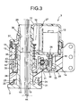
Fig. 3 is a vertical cross section of the electronic unit; -
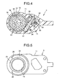
Fig. 4 is a horizontal cross section of the electronic unit; -
Fig. 5 is a bottom plan view of a gear case shown inFig. 2 ; -
Fig. 6 is a top view of the electronic unit without a cover shown inFig. 2 ; -
Fig. 7 is an exploded view of a clutch gear and a gear holder shown inFig. 2 ; -
Fig. 8 is a vertical cross section of a part of the electronic unit for explaining a disengaged state of clutch protrusion portions of a clutch gear shown inFig. 2 and clutch recess portions of a gear holder shown inFig. 2 ; -
Fig. 9 is a schematic diagram for explaining engagement between the clutch protruding portions and the clutch recess portions; and -
Fig. 10 is a schematic diagram for explaining disengagement between the clutch protruding portions and the clutch recess portions. - Exemplary embodiments of the present invention are explained in detail below with reference to the accompanying drawings.
- A vehicle outside
mirror device 1 according to an embodiment of the present invention is explained in detail below.Fig. 1 is a schematic diagram of the vehicle outsidemirror device 1. The vehicle outsidemirror device 1 is an electronic door mirror device, and it is for attaching to a right door (not shown) of a vehicle (not shown). A vehicle outside mirror device for attaching to a left door basically has the same structure as that of the vehicle outsidemirror device 1 except that it is for a left hand application. - As shown in
Fig. 1 , the vehicle outsidemirror device 1 includes amirror assembly 2, anelectronic unit 3, and a base 4 (mirror base). Thebase 4 is fixed to the right door. Themirror assembly 2 is held by thebase 4 in such a manner that themirror assembly 2 is rotatable with respect to the right door. - The
mirror assembly 2 includes amirror housing 5, anattachment bracket 6, apower unit 7, and amirror 8. Theattachment bracket 6 is attached to an inner wall of themirror housing 5. Thepower unit 7 is attached to theattachment bracket 6. Themirror 8 is movably attached to thepower unit 7 so as to incline vertically and horizontally. - As shown in
Fig. 2 , theelectronic unit 3 includes ashaft holder 9, ashaft 10, agear case 11, acover 12, amotor 13, adeceleration mechanism 14 as a torque transmission mechanism, aclutch mechanism 15, aplate 16, afixation plate 17, and asubstrate 27. Thedeceleration mechanism 14 is rotatably borne by theplate 16. Theplate 16 and thedeceleration mechanism 14 constitute a subassembly. - The
shaft holder 9 is fixed to thebase 4. Theshaft 10 is integral with theshaft holder 9. Theshaft 10 is hollow, andharnesses 44 are passed though the shaft 10 (seeFig. 3 ). Thegear case 11 and thecover 12 are rotatably attached to theshaft 10. Thegear case 11 is attached to theattachment bracket 6. Themotor 13, thedeceleration mechanism 14, theclutch mechanism 15, and theplate 16 are housed in thegear case 11. - The
gear case 11 is made of, for example, resin such as nylon. As shown inFigs. 2 to 7 , a cross section of thegear case 11 has a concave shape, i.e., thegear case 11 has a closed portion on one side (bottom side) and an open portion on the other side (top side). In other words, thehousing unit 18 having a cross section in a concave shape, i.e., thehousing unit 18 having a closed portion on a side of theshaft holder 9 and an open portion on a side of thecover 12, is provided in thegear case 11. Acircular insertion hole 19 is formed on the closed side of thegear case 11. Theshaft 10 is inserted into theinsertion hole 19 such that thegear case 11 is rotatable on theshaft 10. - As shown in
Figs. 2 and3 , aguide protruding portion 20 having an annular shape and that is concentric with theshaft 10 is provided integrally with an upper surface of theshaft holder 9. In addition, astopper protruding portion 21 having an arc shape and that is concentric with theshaft 10 is provided integrally with an outer surface of theguide protruding portion 20. Thestopper protruding portion 21 has stopperfacets 22 on both ends. Only one of thestopper facets 22 is seen inFig. 2 because the other stopper facet is behind theshaft 10. As shown inFigs. 3 and5 , aguide groove 23 having an annular shape and the same center axis as that of theshaft 10 is formed in a bottom surface of thegear case 11. In addition, aguide groove 24 having an arc shape and that is concentric with theshaft 10 is formed in the bottom surface of thegear case 11 in an outer position with respect to an outer circumference of theguide groove 23. In addition,stopper facets 25 are formed in thegear case 11 at both boundaries between theguide groove 23 and theguide groove 24. - The
guide protruding portion 20 and thestopper protruding portion 21 are inserted into and fitted to theguide groove 23 and theguide groove 24. Theguide groove 23, theguide groove 24, theguide protruding portion 20, and thestopper protruding portion 21 constitute a guide unit that guides themirror assembly 2 to rotate with respect to thebase 4. - When the
mirror assembly 2 is rotated forward (i.e., clockwise) from a use position C shown inFig. 1 to a storage position B shown inFig. 1 or rotated backward (counterclockwise) from the use position C to a forward inclination position A shown inFig. 1 , thestopper facets 22 of thestopper protruding portion 21 abut with thestopper facets 25 of thegear case 11. Themirror assembly 2 can not be rotated further when thestopper facets 22 abut with thestopper facets 25, which prevents hitting of themirror assembly 2 with the vehicle body. Thus, theguide groove 23, theguide groove 24, theguide protruding portion 20, and thestopper protruding portion 21 constitute a stopper unit that prevents hitting of themirror assembly 2 with the vehicle body. - The
cover 12 is made of resin. The cross section of thecover 12 has an inverted concave shape as shown inFigs. 2 ,3 , and7 , i.e., thecover 12 has a closed portion on one (top) side and an open portion on the other (bottom) side. In other words, thehousing unit 18 having a cross section in an inverted concave shape, i.e., thehousing unit 18 having a closed portion on one side and having an open portion on a side of thegear case 11, is provided to thecover 12. A harness insertioncylindrical portion 26 that communicates with theshaft 10 is integrally mounted to thecover 12. - A periphery of the
housing unit 18 of thegear case 11 and a periphery of thehousing unit 18 of thecover 12 are engaged and fixed to each other. Alternatively, for example, thegear case 11 and thecover 12 can be fixed to each other by adhering with an adhesive. - The
substrate 27 is attached to theplate 16. A switch circuit that controls (drives and stops) themotor 13 is mounted on thesubstrate 27. Aninsertion hole 39 that communicates with the harness insertioncylindrical portion 26 is formed in thecover 12. Theshaft 10 is inserted into theinsertion hole 39. Thecover 12 and thegear case 11 are rotatably attached to theshaft 10. - As shown in
Figs. 2 to 4 , thedeceleration mechanism 14 and theclutch mechanism 15 are positioned between anoutput shaft 28 of themotor 13 and theshaft 10, and thedeceleration mechanism 14 and theclutch mechanism 15 transmit a rotational force of themotor 13 to theshaft 10. Themotor 13, thedeceleration mechanism 14, and theclutch mechanism 15 rotate themirror assembly 2 with respect to theshaft 10. - The
deceleration mechanism 14 includes afirst worm gear 29, i.e., a first gear, ahelical gear 30, i.e., a second gear, and engages with thefirst worm gear 29, asecond worm gear 31, i.e., a third gear, and aclutch gear 32, i.e., a last gear, and with which thesecond worm gear 31 is engaged. - The
first worm gear 29 is rotatably borne by theplate 16 via apin 33. Thefirst worm gear 29 is connected to theoutput shaft 28. Thehelical gear 30 is rotatably bored by theplate 16. Thesecond worm gear 31 is integrally and rotatably engaged with thehelical gear 30 and rotatably borne by thegear case 11. - The
clutch mechanism 15 includes theclutch gear 32 made of metal, aclutch holder 35 made of metal, aspring 36, apush nut 37, and awasher 38 made of metal. Thewasher 38, theclutch holder 35, theclutch gear 32, and thespring 36 are sequentially fitted to theshaft 10, and thepush nut 37 is fixed to theshaft 10, so that thespring 36 is compressed by thepush nut 37. Theclutch gear 32 and theclutch holder 35 are engaged with each other such that they can be disengaged from each other. When thesecond worm gear 31 and theclutch gear 32 are engaged with each other, a rotational force of themotor 13 is transmitted to theshaft 10. - The
clutch gear 32 and theclutch holder 35 constitute a clutch mechanism. Theclutch gear 32 is attached to theshaft 10 so as to be rotatable and movable in a direction of an axis (hereinafter, "axial direction") of theshaft 10. Theclutch holder 35 is attached to theshaft 10 so as not to be rotatable and so as to be movable in the axial direction of theshaft 10. As shown inFig. 7 , a plurality of, for example three, clutch protrudingportions 40 are formed on a bottom surface of theclutch gear 32 and a plurality of, for example three,clutch recess portions 41 are formed in an upper surface of theclutch holder 35. The clutch protrudingportions 40 are positioned at equal intervals on the bottom surface of theclutch gear 32 and theclutch recess portions 41 are positioned at equal intervals on the upper surface of theclutch holder 35. When an urging force of thespring 36 acts on theclutch gear 32, the clutch protrudingportions 40 and theclutch recess portions 41 engage with each other. In other words, when the urging force of thespring 36 acts on theclutch gear 32, theclutch gear 32 and theclutch holder 35 are in an engaged state. On the other hand, when a force (external force) of a predetermined amount or more is applied to themirror assembly 2 with, for example, hand, the clutch protrudingportions 40 and theclutch recess portions 41 disengage from each other (released). In other words, when the predetermined force is applied to themirror assembly 2, theclutch gear 32 and theclutch holder 35 disengaged from each other (released). - Guide portions are formed in the
clutch gear 32 in an inner position with respect to an outer circumference of theclutch gear 32 and in theclutch holder 35 in an inner position with respect to an outer circumference of theclutch holder 35. The guide portions guide theclutch gear 32 to move with respect to theclutch holder 35 in an axial direction thereof (i.e., with respect to theshaft 10 in the axial direction of the shaft 10). Specifically, as shown inFigs. 3 ,7, and 8 , aguide protruding portion 42 that is cylindrical (or, in which at least one arc is provided) is integrally provided as a step to the upper surface of theclutch holder 35 in an inner position with respect to the outer circumference of theclutch holder 35. On the other hand, aguide hole 43 having a circular shape (or, in which at least one arc is formed) is formed in an inner position with respect to an outer circumference of theclutch gear 32. Theguide protruding portion 42 is inserted into theguide hole 43 so as to be rotatable and movable in the axial direction of theshaft 10. The outer circumference of theguide protruding portion 42 and an inner circumference of theguide hole 43 contact with each other and theguide protruding portion 42 and theguide hole 43 guide theclutch gear 32 to move in the axial direction of theshaft 10. An outer diameter of the outer circumference of theguide protruding portion 42 and an inner diameter of an inner circumference of theguide hole 43 is equal or approximately equal to each other, i.e., or the outer diameter of the outer circumference of theguide protruding portion 42 is slightly larger than the inner diameter of the inner periphery of theguide hole 43. - The
clutch gear 32 is opposed to thespring 36 and theclutch holder 35 is opposed to thewasher 38 and thegear case 11. Thewasher 38 is fixed to thegear case 11. Theclutch holder 35 and thewasher 38 include a rotation range regulating mechanism that regulates a range of automatic rotation of themirror assembly 2 between the use position C and the storage position B. Themirror assembly 2 can be stopped at the storage position B not only because of the regulation by the automatic rotation range regulating mechanism but also because thestopper facets 25 of thegear case 11 make contact with thestopper facets 22 of thestopper protruding portion 21. - How the
mirror assembly 2 is automatically rotated from the use position C to the storage position B is explained below. When themirror assembly 2 is in the use position C, the clutch protrudingportions 40 of theclutch gear 32 and theclutch recess portions 41 of theclutch holder 35 are engaged with each other as shown inFig. 9 , i.e., theclutch gear 32 and theclutch holder 35 are engaged with each other. Therefore, theclutch gear 32 is not rotatable on theshaft 10. - When the driver of the vehicle operates a switch (not shown) provided inside the vehicle in a state that the
mirror assembly 2 is in the use position C, themotor 13 generates a rotational force. The rotational force of themotor 13 is transmitted via theoutput shaft 28 and thedeceleration mechanism 14 to theclutch gear 32 that is fixed to theshaft 10. Because of the rotational force of themotor 13, the clutch protrudingportions 40 of theclutch gear 32 and theclutch recess portions 41 of theclutch holder 35 are maintained engaged with each other. Thus, in addition to theclutch holder 35, theclutch gear 32 is not rotatable on theshaft 10. Therefore, thesecond worm gear 31 rotates on theclutch gear 32, and thus, themirror assembly 2 is rotated on theshaft 10. As a result, themirror assembly 2 rotates from the use position C to the storage position B. When themirror assembly 2 is positioned in the storage position B, a current supplied to the motor 13 (operation current) increases as a result of regulation by the automatic rotation range regulating mechanism. When the current reaches a predetermined value, the switch circuit operates to stop supply of the current to themotor 13. As a result, themirror assembly 2 stops at the storage position B. When themirror assembly 2 has reached the storage position B, thestopper facets 22 of thestopper protruding portion 21 make contact with thestopper facets 25 of thegear case 11. Therefore, themirror assembly 2 can not rotate further, which prevents hitting of themirror assembly 2 with the vehicle body. - How the
mirror assembly 2 is automatically rotated from the storage position B to the use position C is explained below. When the driver operates the switch arranged inside the vehicle in a state that the mirror assembly is in the storage position B, themotor 13 generates a rotational force. Because of the rotational force of themotor 13, thegear case 11 rotates counterclockwise on theshaft 10, so that themirror assembly 2 rotates counterclockwise from the storage position B. When themirror assembly 2 reaches the use position C, the current (operation current) supplied to themotor 13 increases as a result of regulation by the automatic rotation range regulating mechanism. When the current reaches a predetermined value, the switch circuit operates to stop the supply of the current to themotor 13. As a result, themirror assembly 2 stops at the storage position C. - How the
mirror assembly 2 is manually rotated between the use position C and the storage position B is explained below. When manually rotating themirror assembly 2 clockwise from the use position C to the storage position B or counterclockwise from the storage position B to the use position C, the driver pushes (or pulls) themirror assembly 2 is a desired direction, i.e., the driver applies a force (external force) of a predetermined amount or more in a desired direction to themirror assembly 2. As a result, as shown inFig. 10 , an inclining surface of the clutch protrudingportion 40 slips up on an inclining surface of theclutch recess portion 41. Therefore, theclutch gear 32 rotates and moves upward with respect to theclutch holder 35, which is not rotatable, in the axial direction of theshaft 10 against the urging force of thespring 36. - The outer circumference of the
guide protruding portion 42 of theclutch holder 35 and the inner circumference of theguide hole 43 of theclutch gear 32 contact with each other and theguide protruding portion 42 and theguide hole 43 guide theclutch gear 32. Therefore, theclutch gear 32 rotates and moves upward with respect to theclutch holder 35 smoothly. As a result, theclutch recess portions 41 and the clutch protrudingportions 40 are disengaged from each other and theclutch gear 32 is rotatable on theshaft 10. Thus, theclutch gear 32 rotates on theshaft 10 with thesecond worm gear 31 of thedeceleration mechanism 14. - Because the
clutch gear 32 rotates with thesecond worm gear 31 on theshaft 10, themirror assembly 2 rotates on theshaft 10. In this manner, themirror assembly 2 is manually rotated clockwise from the use position C to the storage position B or counterclockwise from the storage unit B to the use position C. When themirror assembly 2 is manually rotated from the use position C to the storage position B, the clutch protrudingportions 40 of theclutch gear 32 and theclutch recess portions 41 of theclutch holder 35 are engaged with each other by the urging force of thespring 36, i.e., theclutch gear 32 and theclutch holder 35 are engaged with each other. - When manually rotating the
mirror assembly 2 positioned in the use position C in the counterclockwise direction, the driver pushes (or pulls) themirror assembly 2 in the counterclockwise direction. In this case, the clutch protrudingportions 40 of theclutch gear 32 and theclutch recess portions 41 of theclutch holder 35 are maintained engaged with each other, i.e., theclutch gear 32 and theclutch holder 35 are maintained engaged with each other. Therefore, theclutch gear 32 and theclutch holder 35 move upwards against the urging force of thespring 36. In other words, the automatic rotation range regulating mechanism does not regulate the rotation of themirror assembly 2. Thus, themirror assembly 2 is rotated counterclockwise from the use position C to the forward inclination position A. When themirror assembly 2 reaches the forward inclination position A, thestopper facets 22 of thestopper protruding portion 21 abut with thestopper facets 25 of thegear case 11. Therefore, the rotation of themirror assembly 2 can not be rotated further, which prevents hitting of themirror assembly 2 with the vehicle body. - When manually rotating the
mirror assembly 2 positioned in the forward inclination position A in the clockwise direction, the driver pushes (or pulls) themirror assembly 2 in the clockwise direction. As a result, thegear case 11 attached to themirror assembly 2 rotates clockwise. Therefore, themirror assembly 2 rotates clockwise from the forward inclination position A to the use position C. When themirror assembly 2 reaches the use position C, theclutch gear 32 and theclutch holder 35 move downward as shown inFig. 3 because of the urging force of thespring 36. Thus, themirror assembly 2 stops at the use position C because of the regulation by the automatic rotation range regulating mechanism. - When a load of a predetermined amount or more is undesirably applied to the
mirror assembly 2, clockwise or counterclockwise, themirror assembly 2 rotates between the use position C and the storage position B or between the use position C and the forward inclination position A. Such motion buffers the applied force and prevents damage of the vehicleexternal mirror device 1. - Effects of the vehicle outside
mirror device 1 are explained below. - Because the
guide hole 43 and theguide protruding portion 42 are provided in the inner position with respect to the outer circumference of theclutch holder 35 and the inner position with respect to the outer circumference of theclutch gear 32, theclutch gear 32 and theclutch holder 35 can have same outer diameters. In other words, the outer diameter of theclutch gear 32 can be made smaller than that of a conventional gear plate of a conventional vehicle outside mirror device. Therefore, theclutch mechanism 15 can be made smaller as compared with the conventional one, and thus, theelectronic unit 3 can be made smaller compared with a conventional one. - Furthermore, the
clutch gear 32 is provided with theguide hole 43 and theclutch holder 35 is provided with theguide protruding portion 42. Therefore, theclutch gear 32 and theclutch holder 35 are engaged with each other or disengaged from each other while being guided by theguide hole 43 and theguide protruding portion 42. This achieves smooth engagement and disengagement between theclutch gear 32 and theclutch holder 35. - Furthermore, a harness can be inserted into the
shaft 10. Because theclutch gear 32 can have a smaller outer diameter than that of the gear plate of the conventional vehicle outside mirror device, theshaft 10 can have a larger diameter than that of the conventional vehicle outside mirror device. Therefore, it is possible to insert more harnesses into the shaft 10 (about 16 harnesses can be inserted into theshaft 10 at maximum in this embodiment) compared with the conventional vehicle outside mirror device. - The vehicle outside
mirror device 1 is an electronic foldable door mirror device. However, the same technology can be applied to other vehicle outside mirror devices such as vehicle fender mirrors. - It has been explained above that the
clutch gear 32 and theclutch holder 35 are attached to theshaft 10 so as to movable in the axial direction of theshaft 10. However, any one of theclutch gear 32 and theclutch holder 35 can be attached to theshaft 10 so as to be movable in the axial direction of theshaft 10. - Furthermore, it has been explained above that the
clutch gear 32 has theguide hole 43 and theclutch holder 35 has theguide protruding portion 42. Alternatively, theclutch gear 32 can have a guide protruding portion and theclutch holder 35 can have a guide hole. - Although the invention has been described with respect to specific embodiments for a complete and clear disclosure, the appended claims are not to be thus limited but are to be construed as embodying all modifications and alternative constructions that may occur to one skilled in the art that fairly fall within the basic teaching herein set forth.
Claims (2)
- A vehicle outside mirror device comprising:a mirror assembly (2);an electronic unit (3); anda base (4) configured to be attachable to a vehicle body,the electronic unit (3) includinga shaft holder (9) that is fixed to the base;a shaft (10) that is fixed to the shaft holder;a casing (11, 12) that houses the mirror assembly and that is rotatably attached to the shaft; anda driving mechanism (14, 15) that is housed in the casing and that rotates the mirror assembly with respect to the shaft, the driving mechanism including a motor (13) and a rotational force transmitting mechanism, the rotational force transmitting mechanism including a deceleration unit (14) and a clutch unit (15), the clutch unit includinga clutch gear (32) that is rotatably attached to the shaft, and that is a last gear in the deceleration unit; anda clutch holder (35) that is attached to the shaft so as not to be rotatable, whereinthe clutch gear and the clutch holder are engaged with each other by an urging force,the clutch gear and the clutch holder are disengaged from each other when a force of a predetermined amount or more acts on the mirror assembly,the clutch gear has a first guide portion (42) that is formed in an inner position with respect to an outer circumference of the clutch gear and the clutch holder has a second guide portion (43) that is formed in an inner position with respect to an outer circumference of the clutch holder, andthe clutch gear and the clutch holder relatively move in a direction of an axis of the shaft by guiding along the first guide portion and the second guide portion.
- The vehicle outside mirror device according to claim 1, wherein the shaft (10) is hollow whereby a harness can be inserted into the shaft.
Applications Claiming Priority (1)
| Application Number | Priority Date | Filing Date | Title |
|---|---|---|---|
| JP2007144530A JP2008296721A (en) | 2007-05-31 | 2007-05-31 | Outside mirror device for vehicle |
Publications (3)
| Publication Number | Publication Date |
|---|---|
| EP1997683A2 true EP1997683A2 (en) | 2008-12-03 |
| EP1997683A3 EP1997683A3 (en) | 2010-04-14 |
| EP1997683B1 EP1997683B1 (en) | 2013-03-06 |
Family
ID=39665939
Family Applications (1)
| Application Number | Title | Priority Date | Filing Date |
|---|---|---|---|
| EP08009735A Not-in-force EP1997683B1 (en) | 2007-05-31 | 2008-05-28 | Vehicle outside mirror device |
Country Status (5)
| Country | Link |
|---|---|
| US (1) | US20090040639A1 (en) |
| EP (1) | EP1997683B1 (en) |
| JP (1) | JP2008296721A (en) |
| KR (1) | KR100909016B1 (en) |
| CN (1) | CN101314341A (en) |
Cited By (1)
| Publication number | Priority date | Publication date | Assignee | Title |
|---|---|---|---|---|
| ES2781124A1 (en) * | 2019-02-26 | 2020-08-28 | Compania Levantina De Reductores S L | EXTERIOR REAR VIEW MIRROR ROTATION MECHANISM FOR VEHICLES AND REAR VIEW MIRROR INCLUDING IT (Machine-translation by Google Translate, not legally binding) |
Families Citing this family (9)
| Publication number | Priority date | Publication date | Assignee | Title |
|---|---|---|---|---|
| JP5488429B2 (en) * | 2010-11-26 | 2014-05-14 | 市光工業株式会社 | Outside mirror device for vehicle |
| JP2013075618A (en) * | 2011-09-30 | 2013-04-25 | Ichikoh Ind Ltd | Vehicle outside mirror device |
| EP2716927B1 (en) * | 2012-10-02 | 2016-03-09 | Fico Mirrors, S.A. | Clutch suitable for vehicles' powered mirrors |
| DE102013201434B3 (en) | 2013-01-29 | 2014-05-28 | Mekra Lang Gmbh & Co. Kg | Electric rotary adjustment unit and indirect vision system for vehicles with such an adjustment |
| US20150335093A1 (en) * | 2014-05-20 | 2015-11-26 | Honeywell International, Inc. | Hard hat adapter |
| JP6482353B2 (en) | 2015-03-31 | 2019-03-13 | 株式会社村上開明堂 | Electric retractable visual recognition device for vehicles |
| WO2018206458A1 (en) * | 2017-05-11 | 2018-11-15 | Smr Patents Sarl | Drive mechanism and rear view device |
| ES2781125B2 (en) * | 2019-02-26 | 2021-02-25 | Compania Levantina De Reductores S L | OUTER REAR VIEW MIRROR MOUNTING STRUCTURE FIXING ASSEMBLY FOR VEHICLES AND INCLUDING REAR VIEW MIRROR |
| KR102654582B1 (en) * | 2019-05-08 | 2024-04-03 | 현대자동차주식회사 | Structure for Camera Mirror System Disposed inside the Panel of Vehicle |
Citations (1)
| Publication number | Priority date | Publication date | Assignee | Title |
|---|---|---|---|---|
| JP2002036955A (en) | 2000-07-25 | 2002-02-06 | Tokai Rika Co Ltd | Mirror device for vehicle |
Family Cites Families (17)
| Publication number | Priority date | Publication date | Assignee | Title |
|---|---|---|---|---|
| EP0314135B1 (en) * | 1987-10-27 | 1993-08-04 | Ichikoh Industries Limited | Electrically swingable door mirror |
| DE69018238T2 (en) * | 1989-08-31 | 1995-07-27 | Ichiko Industries Ltd | ELECTRICALLY FOLDABLE DOOR MIRROR. |
| JP3022159B2 (en) * | 1994-04-19 | 2000-03-15 | 株式会社村上開明堂 | Door mirror drive control section seal structure |
| JP3208994B2 (en) * | 1994-06-09 | 2001-09-17 | 市光工業株式会社 | Drive device for rearview mirror device for vehicles |
| JP3008334U (en) * | 1994-08-25 | 1995-03-14 | 株式会社村上開明堂 | Electric retractable door mirror deceleration mechanism |
| JPH08310303A (en) * | 1995-05-22 | 1996-11-26 | Ichikoh Ind Ltd | Remote control mirror overload prevention mechanism |
| EP0881124B1 (en) * | 1997-05-29 | 2004-03-31 | Schefenacker Vision Systems Australia Pty Ltd | A mirror operating mechanism |
| JP3795194B2 (en) * | 1997-08-20 | 2006-07-12 | 株式会社東海理化電機製作所 | Door mirror electric storage device |
| DE60212745T2 (en) * | 2001-03-19 | 2006-11-02 | Kabushiki Kaisha Tokai Rika Denki Seisakusho | Automotive mirror assembly |
| JP3887543B2 (en) * | 2001-03-19 | 2007-02-28 | 株式会社東海理化電機製作所 | Mirror device for vehicle |
| JP2004009806A (en) * | 2002-06-04 | 2004-01-15 | Ichikoh Ind Ltd | Outer mirror for vehicles |
| JP2004082953A (en) | 2002-08-28 | 2004-03-18 | Ichikoh Ind Ltd | Electric retractable door mirror |
| JP4054252B2 (en) * | 2002-12-04 | 2008-02-27 | 株式会社東海理化電機製作所 | Mirror device for vehicle and storage mechanism for vehicle outer mirror device |
| JP4122993B2 (en) * | 2003-02-04 | 2008-07-23 | 市光工業株式会社 | Electric retractable door mirror |
| JP2005193818A (en) * | 2004-01-08 | 2005-07-21 | Ishizaki Honten:Kk | Electric mirror |
| JP2006007925A (en) * | 2004-06-24 | 2006-01-12 | Ichikoh Ind Ltd | Outside mirror for vehicle |
| JP2008007706A (en) * | 2006-06-30 | 2008-01-17 | Lion Corp | Liquid detergent composition |
-
2007
- 2007-05-31 JP JP2007144530A patent/JP2008296721A/en active Pending
-
2008
- 2008-05-06 KR KR1020080041923A patent/KR100909016B1/en not_active Expired - Fee Related
- 2008-05-27 CN CNA2008101084085A patent/CN101314341A/en active Pending
- 2008-05-28 US US12/128,295 patent/US20090040639A1/en not_active Abandoned
- 2008-05-28 EP EP08009735A patent/EP1997683B1/en not_active Not-in-force
Patent Citations (1)
| Publication number | Priority date | Publication date | Assignee | Title |
|---|---|---|---|---|
| JP2002036955A (en) | 2000-07-25 | 2002-02-06 | Tokai Rika Co Ltd | Mirror device for vehicle |
Cited By (2)
| Publication number | Priority date | Publication date | Assignee | Title |
|---|---|---|---|---|
| ES2781124A1 (en) * | 2019-02-26 | 2020-08-28 | Compania Levantina De Reductores S L | EXTERIOR REAR VIEW MIRROR ROTATION MECHANISM FOR VEHICLES AND REAR VIEW MIRROR INCLUDING IT (Machine-translation by Google Translate, not legally binding) |
| WO2020174108A1 (en) * | 2019-02-26 | 2020-09-03 | Compañía Levantina De Reductores, S.L. | Mechanism for rotating a side mirror for vehicles and side mirror including same |
Also Published As
| Publication number | Publication date |
|---|---|
| EP1997683A3 (en) | 2010-04-14 |
| KR100909016B1 (en) | 2009-07-22 |
| CN101314341A (en) | 2008-12-03 |
| US20090040639A1 (en) | 2009-02-12 |
| JP2008296721A (en) | 2008-12-11 |
| EP1997683B1 (en) | 2013-03-06 |
| KR20080105995A (en) | 2008-12-04 |
Similar Documents
| Publication | Publication Date | Title |
|---|---|---|
| EP1997683A2 (en) | Vehicle outside mirror device | |
| EP1997682A1 (en) | Vehicle outside mirror device | |
| EP2368762B1 (en) | Vehicle outside mirror device | |
| US12024093B2 (en) | Combined actuator for mirror folding and lifting, rear view device and vehicle | |
| EP1908635B1 (en) | Vehicle outside mirror device | |
| US10807534B2 (en) | Electric retractable view device for vehicle | |
| EP2543546B1 (en) | Vehicle outside mirror device | |
| US20100296185A1 (en) | Shaft structure of retractable outer mirror | |
| EP2574504A1 (en) | Vehicle outside mirror device | |
| KR101837106B1 (en) | Outside mirror device for vehicle | |
| US20180111557A1 (en) | Electric retractable view device for vehicle | |
| EP2644452A1 (en) | Vehicle outside mirror device | |
| EP2377726B1 (en) | Vehicle outside mirror device | |
| US6769781B2 (en) | Remote control mirror apparatus for automobile | |
| JP2008296720A (en) | Outside mirror device for vehicle | |
| JP7703375B2 (en) | Mirror surface angle adjustment unit for vehicle outside mirror device, vehicle outside mirror device | |
| JPH0872612A (en) | Vehicle mirror | |
| JP3988716B2 (en) | Electric storage device for vehicle | |
| JP3209002B2 (en) | Outer mirror device for vehicles | |
| JP2003011725A (en) | Outer mirror device for vehicles | |
| JP2008296718A (en) | Outside mirror device for vehicle | |
| JP2003011724A (en) | Outer mirror device for vehicles | |
| JPH10258683A (en) | Outer mirror device for vehicles | |
| JP2013063781A (en) | Outside mirror device for vehicle |
Legal Events
| Date | Code | Title | Description |
|---|---|---|---|
| PUAI | Public reference made under article 153(3) epc to a published international application that has entered the european phase |
Free format text: ORIGINAL CODE: 0009012 |
|
| AK | Designated contracting states |
Kind code of ref document: A2 Designated state(s): AT BE BG CH CY CZ DE DK EE ES FI FR GB GR HR HU IE IS IT LI LT LU LV MC MT NL NO PL PT RO SE SI SK TR |
|
| AX | Request for extension of the european patent |
Extension state: AL BA MK RS |
|
| PUAL | Search report despatched |
Free format text: ORIGINAL CODE: 0009013 |
|
| AK | Designated contracting states |
Kind code of ref document: A3 Designated state(s): AT BE BG CH CY CZ DE DK EE ES FI FR GB GR HR HU IE IS IT LI LT LU LV MC MT NL NO PL PT RO SE SI SK TR |
|
| AX | Request for extension of the european patent |
Extension state: AL BA MK RS |
|
| 17P | Request for examination filed |
Effective date: 20100726 |
|
| AKX | Designation fees paid |
Designated state(s): DE FR GB |
|
| 17Q | First examination report despatched |
Effective date: 20110418 |
|
| GRAP | Despatch of communication of intention to grant a patent |
Free format text: ORIGINAL CODE: EPIDOSNIGR1 |
|
| GRAS | Grant fee paid |
Free format text: ORIGINAL CODE: EPIDOSNIGR3 |
|
| GRAA | (expected) grant |
Free format text: ORIGINAL CODE: 0009210 |
|
| AK | Designated contracting states |
Kind code of ref document: B1 Designated state(s): DE FR GB |
|
| REG | Reference to a national code |
Ref country code: GB Ref legal event code: FG4D |
|
| REG | Reference to a national code |
Ref country code: DE Ref legal event code: R096 Ref document number: 602008022637 Country of ref document: DE Effective date: 20130425 |
|
| PLBE | No opposition filed within time limit |
Free format text: ORIGINAL CODE: 0009261 |
|
| STAA | Information on the status of an ep patent application or granted ep patent |
Free format text: STATUS: NO OPPOSITION FILED WITHIN TIME LIMIT |
|
| PG25 | Lapsed in a contracting state [announced via postgrant information from national office to epo] |
Ref country code: DE Free format text: LAPSE BECAUSE OF NON-PAYMENT OF DUE FEES Effective date: 20131203 |
|
| 26N | No opposition filed |
Effective date: 20131209 |
|
| GBPC | Gb: european patent ceased through non-payment of renewal fee |
Effective date: 20130606 |
|
| REG | Reference to a national code |
Ref country code: FR Ref legal event code: ST Effective date: 20140131 |
|
| REG | Reference to a national code |
Ref country code: DE Ref legal event code: R119 Ref document number: 602008022637 Country of ref document: DE Effective date: 20131203 |
|
| PG25 | Lapsed in a contracting state [announced via postgrant information from national office to epo] |
Ref country code: GB Free format text: LAPSE BECAUSE OF NON-PAYMENT OF DUE FEES Effective date: 20130606 |
|
| PG25 | Lapsed in a contracting state [announced via postgrant information from national office to epo] |
Ref country code: FR Free format text: LAPSE BECAUSE OF NON-PAYMENT OF DUE FEES Effective date: 20130531 |