EP1997666B1 - Verfahren und Vorrichtung zur Erkennung eines Ermüdungszustands eines Fahrers eines Kraftfahrzeugs - Google Patents
Verfahren und Vorrichtung zur Erkennung eines Ermüdungszustands eines Fahrers eines Kraftfahrzeugs Download PDFInfo
- Publication number
- EP1997666B1 EP1997666B1 EP08009171A EP08009171A EP1997666B1 EP 1997666 B1 EP1997666 B1 EP 1997666B1 EP 08009171 A EP08009171 A EP 08009171A EP 08009171 A EP08009171 A EP 08009171A EP 1997666 B1 EP1997666 B1 EP 1997666B1
- Authority
- EP
- European Patent Office
- Prior art keywords
- steering
- signal
- steering angle
- driver
- calculated
- Prior art date
- Legal status (The legal status is an assumption and is not a legal conclusion. Google has not performed a legal analysis and makes no representation as to the accuracy of the status listed.)
- Active
Links
Images

Classifications
-
- B—PERFORMING OPERATIONS; TRANSPORTING
- B60—VEHICLES IN GENERAL
- B60K—ARRANGEMENT OR MOUNTING OF PROPULSION UNITS OR OF TRANSMISSIONS IN VEHICLES; ARRANGEMENT OR MOUNTING OF PLURAL DIVERSE PRIME-MOVERS IN VEHICLES; AUXILIARY DRIVES FOR VEHICLES; INSTRUMENTATION OR DASHBOARDS FOR VEHICLES; ARRANGEMENTS IN CONNECTION WITH COOLING, AIR INTAKE, GAS EXHAUST OR FUEL SUPPLY OF PROPULSION UNITS IN VEHICLES
- B60K28/00—Safety devices for propulsion-unit control, specially adapted for, or arranged in, vehicles, e.g. preventing fuel supply or ignition in the event of potentially dangerous conditions
- B60K28/02—Safety devices for propulsion-unit control, specially adapted for, or arranged in, vehicles, e.g. preventing fuel supply or ignition in the event of potentially dangerous conditions responsive to conditions relating to the driver
- B60K28/06—Safety devices for propulsion-unit control, specially adapted for, or arranged in, vehicles, e.g. preventing fuel supply or ignition in the event of potentially dangerous conditions responsive to conditions relating to the driver responsive to incapacity of driver
- B60K28/066—Safety devices for propulsion-unit control, specially adapted for, or arranged in, vehicles, e.g. preventing fuel supply or ignition in the event of potentially dangerous conditions responsive to conditions relating to the driver responsive to incapacity of driver actuating a signalling device
-
- B—PERFORMING OPERATIONS; TRANSPORTING
- B60—VEHICLES IN GENERAL
- B60W—CONJOINT CONTROL OF VEHICLE SUB-UNITS OF DIFFERENT TYPE OR DIFFERENT FUNCTION; CONTROL SYSTEMS SPECIALLY ADAPTED FOR HYBRID VEHICLES; ROAD VEHICLE DRIVE CONTROL SYSTEMS FOR PURPOSES NOT RELATED TO THE CONTROL OF A PARTICULAR SUB-UNIT
- B60W40/00—Estimation or calculation of non-directly measurable driving parameters for road vehicle drive control systems not related to the control of a particular sub unit, e.g. by using mathematical models
- B60W40/08—Estimation or calculation of non-directly measurable driving parameters for road vehicle drive control systems not related to the control of a particular sub unit, e.g. by using mathematical models related to drivers or passengers
- B60W40/09—Driving style or behaviour
-
- B—PERFORMING OPERATIONS; TRANSPORTING
- B60—VEHICLES IN GENERAL
- B60W—CONJOINT CONTROL OF VEHICLE SUB-UNITS OF DIFFERENT TYPE OR DIFFERENT FUNCTION; CONTROL SYSTEMS SPECIALLY ADAPTED FOR HYBRID VEHICLES; ROAD VEHICLE DRIVE CONTROL SYSTEMS FOR PURPOSES NOT RELATED TO THE CONTROL OF A PARTICULAR SUB-UNIT
- B60W10/00—Conjoint control of vehicle sub-units of different type or different function
- B60W10/20—Conjoint control of vehicle sub-units of different type or different function including control of steering systems
-
- B—PERFORMING OPERATIONS; TRANSPORTING
- B60—VEHICLES IN GENERAL
- B60W—CONJOINT CONTROL OF VEHICLE SUB-UNITS OF DIFFERENT TYPE OR DIFFERENT FUNCTION; CONTROL SYSTEMS SPECIALLY ADAPTED FOR HYBRID VEHICLES; ROAD VEHICLE DRIVE CONTROL SYSTEMS FOR PURPOSES NOT RELATED TO THE CONTROL OF A PARTICULAR SUB-UNIT
- B60W40/00—Estimation or calculation of non-directly measurable driving parameters for road vehicle drive control systems not related to the control of a particular sub unit, e.g. by using mathematical models
- B60W40/08—Estimation or calculation of non-directly measurable driving parameters for road vehicle drive control systems not related to the control of a particular sub unit, e.g. by using mathematical models related to drivers or passengers
- B60W2040/0818—Inactivity or incapacity of driver
Definitions
- the invention relates to a method for detecting a fatigue state of a driver of a motor vehicle. Furthermore, the invention relates to a corresponding device.
- Methods and devices for detecting a fatigue state of a driver of a motor vehicle are, for example, from EP 1 312 499 A2 , of the DE 10 2004 029 825 A1 , of the DE 10 2005 001 230 A1 and the DE 10 2005 026 456 A1 known.
- EP 1 312 499 A2 and the DE 10 2005 001 230 A1 can be used to detect a state of fatigue on physiological data of the driver such as the lid closure behavior or the skin temperature, which, however, requires additional sensors.
- a steering torque sensor for detecting the driver's request, which usually detects the rotation of a provided in the region of the steering column or shaft torsion bar.
- the signal of the steering torque sensor is taken into account in the regulation of the steering assistance, respectively the steering assist force or the steering assist torque.
- the steering angle calculated in the control unit could be used to detect the state of fatigue.
- a procedure does not always provide satisfactory results. Since the steering wheel and the steering are not rigidly coupled to each other, but, as stated, inter alia, for determining the steering torque, a torsion bar in the steering column between the steering wheel and the steering gear is coupled, deviates the calculated steering angle of the actual angle on the steering wheel.
- the elasticities of the steering also act as a low-pass filter, so that relevant for the detection of fatigue state frequencies are largely outside the observation area. Without a steering angle sensor coupled to the steering wheel, the steering operation of the driver can not be measured with the resolution required for fatigue detection in such a case.
- the invention has for its object to remedy this situation.
- the invention aims, even without a steering angle sensor on the steering wheel to realize a fast and reliable fatigue detection of a driver.
- the course of the steering torque applied by the driver correlates strongly with the steering angle speed on the steering wheel, so that conclusions can be drawn from the course of a signal representing the steering torque on the fatigue state of the driver.
- the evaluation of the waveform can be done with known algorithms. For example, this can be done in the DE 10 2004 029 825 A1 and the DE 10 2005 026 456 A1 illustrated algorithms are used.
- the signal of the steering torque sensor is, for example, a path or angular size, which represents the expansion of a torsion bar or the relative rotation between a coupled via a torsion bar input and output shaft. Since the elasticity of the torsion bar is known, the path or angle size corresponds to the moment to be detected.
- the steering torque sensor detects a torsion of a steering column by means of strain gauges or by means of a rotary encoder.
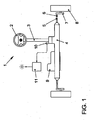
- FIG. 1 shows an electromechanical steering system 1 for a motor vehicle.
- the steering 1 comprises a steering wheel 2, via which a steering torque can be applied by a driver.
- This steering torque is transmitted from the steering wheel 2 via a steering column 3 to a steering gear 4.
- the steering gear 4 has a rack, which is coupled at its ends in each case via a hinge 5 with a tie rod 6.
- Each tie rod 6 engages a supported on the vehicle body wheel carrier 7, on which a vehicle wheel 8 is mounted.
- the steering torque is brought in the form of a steering force along the rack on the tie rods 6 and ultimately to the vehicle wheels 8 to action.
- an additional steering torque is introduced into the steering 1 to assist the driver when steering.
- This additional steering torque is generated in the illustrated steering 1 by an electric motor 9, which can be arranged, for example, axially parallel or coaxial with the rack. It is also possible to arrange the engine elsewhere or to provide a force attack on the steering column 3. For controlling the electric motor 9, this can be equipped with an engine position sensor, not shown.
- the additional steering torque is set as a function of the steering torque applied by the driver. This steering torque representing the driver's request can be detected, for example, via a steering torque sensor 10 on the steering column 3.
- the steering torque sensor 10 may comprise strain gauges, for example, which are applied to a torsion element incorporated into the steering column 3, for example a torsion bar.
- strain gauges for example, which are applied to a torsion element incorporated into the steering column 3, for example a torsion bar.
- other sensor principles can also be used.
- the signal of the steering torque sensor 10 represents the applied steering torque, but from which, if necessary, again an angular dimension can be calculated.
- the output signal of the steering torque sensor 10 is applied to a device 11 for evaluating the signal waveform.
- a device 11 for evaluating the signal waveform In this an algorithm for the conclusion of a fatigue state of the driver is stored. If such a state of fatigue is detected, a warning signal can be generated and displayed to the driver.
- the steering torque sensor 10 can be used in particular algorithms, which on the evaluation of a measured Steering angle velocity based.
- the steering torque can replace the steering angle as an input signal in the algorithm.
- the driver's fatigue condition when the waveform remains within a predetermined bandwidth tolerance band in a predetermined time interval that is only a fraction of a second.
- a predetermined time interval that is only a fraction of a second.
- several such time intervals can be evaluated.
- the means 11 for evaluating the waveform is preferably included in a steering controller.
- the signal of the steering torque sensor 10 is interpreted as a rotation angle.
- This can be summed up with a steering angle calculated in the steering control unit 12, which is provided, for example, to an electronic stability program.
- the sum signal then forms the input signal of the device 11 for evaluating the signal profile, as shown in FIG FIG. 2 is shown.
- the torsion or rotation of the measuring element can be determined via a calibration of the measured electrical voltage with respect to the angle of rotation. This makes it possible to determine the steering angle from the sum of the calculated steering angle of the electromechanical steering and the torsion of the measuring element.
- the position of the rack or the tie rods 6 correlated with the position of the vehicle wheels 8, but in an acting on the rack or on the steering column 3 and equipped with a Motoriagesensor electric motor 9 by means of the signals of the motor position sensor, the position of the rack and thus the angle of the steered vehicle wheels 8 and - directly or indirectly by means of the output signal of the steering torque sensor - and the steering angle are calculated on the steering wheel. Likewise, of course, the corresponding steering angle velocity can also be calculated.
- the idle state via the steering torque sensor and the breaking be detected from the idle state via the calculated for example by means of the motor position sensor steering angle or Lenkwinkei educaen.
- both the observation of the steering angle and the steering wheel speed are suitable for the invention for detecting a fatigue state of a driver in addition to the waveform of the steering torque sensor.
Landscapes
- Engineering & Computer Science (AREA)
- Transportation (AREA)
- Mechanical Engineering (AREA)
- Physics & Mathematics (AREA)
- Automation & Control Theory (AREA)
- Mathematical Physics (AREA)
- Chemical & Material Sciences (AREA)
- Combustion & Propulsion (AREA)
- Power Steering Mechanism (AREA)
- Steering Control In Accordance With Driving Conditions (AREA)
- Auxiliary Drives, Propulsion Controls, And Safety Devices (AREA)
- Testing Of Devices, Machine Parts, Or Other Structures Thereof (AREA)
Priority Applications (1)
| Application Number | Priority Date | Filing Date | Title |
|---|---|---|---|
| PL08009171T PL1997666T3 (pl) | 2007-06-01 | 2008-05-19 | Sposób i urządzenie do rozpoznawania stanu zmęczenia kierowcy pojazdu samochodowego |
Applications Claiming Priority (1)
| Application Number | Priority Date | Filing Date | Title |
|---|---|---|---|
| DE102007025643A DE102007025643A1 (de) | 2007-06-01 | 2007-06-01 | Verfahren und Vorrichtung zur Erkennung eines Ermüdungszustands eines Fahrers eines Kraftfahrzeugs |
Publications (2)
| Publication Number | Publication Date |
|---|---|
| EP1997666A1 EP1997666A1 (de) | 2008-12-03 |
| EP1997666B1 true EP1997666B1 (de) | 2010-11-03 |
Family
ID=39521963
Family Applications (1)
| Application Number | Title | Priority Date | Filing Date |
|---|---|---|---|
| EP08009171A Active EP1997666B1 (de) | 2007-06-01 | 2008-05-19 | Verfahren und Vorrichtung zur Erkennung eines Ermüdungszustands eines Fahrers eines Kraftfahrzeugs |
Country Status (4)
| Country | Link |
|---|---|
| EP (1) | EP1997666B1 (pl) |
| AT (1) | ATE486741T1 (pl) |
| DE (2) | DE102007025643A1 (pl) |
| PL (1) | PL1997666T3 (pl) |
Families Citing this family (9)
| Publication number | Priority date | Publication date | Assignee | Title |
|---|---|---|---|---|
| DE102010034599A1 (de) | 2010-08-16 | 2012-02-16 | Hooshiar Mahdjour | Verfahren zur Erfassung des Benutzerprofils zur Müdigkeitserkennung eines Fahrzeugfahrers |
| DE102010039949A1 (de) | 2010-08-30 | 2012-03-01 | Bayerische Motoren Werke Aktiengesellschaft | Verfahren zur Erkennung fehlender Fahreraktivität am Lenkrad eines Kraftfahrzeugs |
| DE102014008791A1 (de) | 2014-06-11 | 2015-12-17 | Frank Munser-Herzog | Fahrerassistenzsystem und Verfahren zur Müdigkeitserkennung und Sekundenschlaf-Vermeidung eines Fahrzeugführers |
| DE202014004917U1 (de) | 2014-06-11 | 2014-07-14 | Frank Munser-Herzog | Fahrerassistenzsystem zur Müdigkeitserkennung und Sekundenschlaf-Vermeidung eines Fahrzeugführers |
| FR3028827B1 (fr) * | 2014-11-20 | 2018-03-09 | Renault S.A.S. | Procede de detection de la perte de vigilance d'un conducteur de vehicule |
| CN108169015B (zh) * | 2017-12-01 | 2020-06-09 | 中国直升机设计研究所 | 一种尾桨柔性梁扭矩加载试验装置 |
| DE102018204409A1 (de) * | 2018-03-22 | 2019-09-26 | Volkswagen Aktiengesellschaft | Verfahren zum Anzeigen von den Betrieb eines Fahrzeugs betreffende Informationen und Anzeigesystem |
| DE102018220612A1 (de) | 2018-11-29 | 2020-06-04 | Audi Ag | Verfahren zum Schätzen eines Lenkradwinkels |
| CN109823345B (zh) * | 2019-04-03 | 2023-04-18 | 吉林大学 | 一种基于生理信息的安全驾驶系统 |
Family Cites Families (7)
| Publication number | Priority date | Publication date | Assignee | Title |
|---|---|---|---|---|
| SE0002804D0 (sv) * | 2000-08-01 | 2000-08-01 | Promind Ab | Teknik för att fortlöpande kartlägga fordons/förares uppträdande/beteende för att fastställa fordons reaktionskoefficient resp. förares kompetenskoefficient, samt anordning för grafisk presentation av dessa koefficienter |
| JP2003016959A (ja) * | 2001-07-02 | 2003-01-17 | Hitachi Ltd | カラー陰極線管 |
| DE10156509B4 (de) | 2001-11-16 | 2007-12-06 | Audi Ag | Fahrerassistenzsystem |
| DE102004029825A1 (de) | 2004-06-19 | 2006-01-05 | Daimlerchrysler Ag | Verfahren und Vorrichtung zum Detektieren von Müdigkeit bei dem Fahrer eines Fahrzeugs |
| DE102004047861A1 (de) | 2004-10-01 | 2006-04-06 | Daimlerchrysler Ag | Verfahren und Vorrichtung zur Unterstützung des Fahrers eines Fahrzeugs bei der Einhaltung einer Fahrspur |
| DE102005001230A1 (de) | 2005-01-11 | 2006-07-20 | Robert Bosch Gmbh | Verfahren und Vorrichtung zur Fahrerzustandserkennung |
| DE102005026456B4 (de) | 2005-06-09 | 2017-04-20 | Daimler Ag | Verfahren zur Müdigkeitserkennung |
-
2007
- 2007-06-01 DE DE102007025643A patent/DE102007025643A1/de active Pending
-
2008
- 2008-05-19 DE DE502008001687T patent/DE502008001687D1/de active Active
- 2008-05-19 EP EP08009171A patent/EP1997666B1/de active Active
- 2008-05-19 PL PL08009171T patent/PL1997666T3/pl unknown
- 2008-05-19 AT AT08009171T patent/ATE486741T1/de active
Also Published As
| Publication number | Publication date |
|---|---|
| ATE486741T1 (de) | 2010-11-15 |
| DE102007025643A1 (de) | 2008-12-04 |
| EP1997666A1 (de) | 2008-12-03 |
| DE502008001687D1 (de) | 2010-12-16 |
| PL1997666T3 (pl) | 2011-04-29 |
Similar Documents
| Publication | Publication Date | Title |
|---|---|---|
| EP1997666B1 (de) | Verfahren und Vorrichtung zur Erkennung eines Ermüdungszustands eines Fahrers eines Kraftfahrzeugs | |
| DE102007027039B4 (de) | Bestimmung der absoluten Position eines Lenksystems durch einen Linearsensor an der Zahnstange | |
| DE102011002997A1 (de) | Verfahren zum Erkennen einer freihändigen Fahrsituation eines Kraftfahrzeuges | |
| DE102009020157B4 (de) | Verfahren und Vorrichtung zur Berechnung eines virtuellen Rotorwinkels | |
| DE102009026497A1 (de) | Verfahren zum Erkennen interner Reibung in einem Lenksystem | |
| WO2017102375A1 (de) | Verfahren zur zustandsüberwachung einer elektronischen servolenkvorrichtung oder wenigstens eines bestandteils der elektronischen servolenkvorrichtung eines kraftfahrzeugs | |
| DE10206474B4 (de) | Verfahren und Vorrichtung zur Erfassung der Reibung in einer elektrischen oder elektromechanischen Lenkvorrichtung eines Kraftfahrzeugs | |
| EP3898383B1 (de) | Verfahren zur bestimmung eines lenkgefühls eines steer-by-wire-lenksystems | |
| EP1536971B1 (de) | Verfahren und vorrichtung zur erkennung des aufmerksamkeitsgrades eines fahrzeugführers | |
| EP4380844B1 (de) | Verfahren zur überwachung eines lenksystems | |
| DE102022200268A1 (de) | Verfahren zum Betrieb eines Lenksystems | |
| EP2393702B1 (de) | Verfahren und vorrichtung zum betreiben einer lenkanordnung eines kraftfahrzeugs | |
| DE102013218721B4 (de) | Verfahren zur Reduktion von Lenkmomenten einer Lenkung eines Kraftfahrzeugs | |
| EP1970289B1 (de) | Verfahren zum Betrieb einer elektrischen Servolenkvorrichtung | |
| DE19720440A1 (de) | Verfahren zur Regelung einer dynamischen Zustandsgröße eines Fahrzeugs | |
| DE102012023463B4 (de) | Verfahren und Erkennungssystem zur Erkennung eines Luftdruckabfalls in mindestens einem Fahrzeugreifen, sowie ein Fahrzeug mit einem derartigen Erkennungssystem | |
| DE102011105949B4 (de) | Verfahren und Vorrichtung zur Müdigkeits- und/oder Aufmerksamkeitsbeurteilung | |
| DE102009047323A1 (de) | Verfahren und Vorrichtung zum Erkennen eines Ermüdungszustands des Fahrers eines Fahrzeugs | |
| DE102010049431B4 (de) | Verfahren zur Diagnose mindestens einer zu diagnostizierenden Sensoreinheit einer elektromechanischen Lenkung und elektromechanische Lenkung | |
| EP2228283B1 (de) | Verfahren zum Erfassen des Gehalten- oder Nichtgehaltenwerdens einer Lenkhandhabe, Verfahren zum Betreiben eines Fahrerassistenzsystems sowie Kraftfahrzeug | |
| DE102009011853B4 (de) | Elektrische Servolenkungssysteme für Fahrzeuge mit einstellbaren Drehstabfedern | |
| EP2093093A2 (de) | Verfahren und Vorrichtung zur Erkennung fehlender Fahreraktivität am Lenkrad | |
| EP1568570A2 (de) | Berechnung eines Radwinkels eines Fahrzeugs | |
| DE102009019194A1 (de) | Verfahren zum Detektieren der Kondition, insbesondere der Müdigkeit und/oder Unaufmerksamkeit, eines Fahrers eines Kraftfahrzeugs | |
| DE102009060171B4 (de) | Verfahren zum Betrieb eines Kraftfahrzeugs mit einer elektromechanischen Lenkung |
Legal Events
| Date | Code | Title | Description |
|---|---|---|---|
| PUAI | Public reference made under article 153(3) epc to a published international application that has entered the european phase |
Free format text: ORIGINAL CODE: 0009012 |
|
| AK | Designated contracting states |
Kind code of ref document: A1 Designated state(s): AT BE BG CH CY CZ DE DK EE ES FI FR GB GR HR HU IE IS IT LI LT LU LV MC MT NL NO PL PT RO SE SI SK TR |
|
| AX | Request for extension of the european patent |
Extension state: AL BA MK RS |
|
| 17P | Request for examination filed |
Effective date: 20090603 |
|
| 17Q | First examination report despatched |
Effective date: 20090710 |
|
| AKX | Designation fees paid |
Designated state(s): AT BE BG CH CY CZ DE DK EE ES FI FR GB GR HR HU IE IS IT LI LT LU LV MC MT NL NO PL PT RO SE SI SK TR |
|
| GRAC | Information related to communication of intention to grant a patent modified |
Free format text: ORIGINAL CODE: EPIDOSCIGR1 |
|
| GRAP | Despatch of communication of intention to grant a patent |
Free format text: ORIGINAL CODE: EPIDOSNIGR1 |
|
| GRAS | Grant fee paid |
Free format text: ORIGINAL CODE: EPIDOSNIGR3 |
|
| GRAA | (expected) grant |
Free format text: ORIGINAL CODE: 0009210 |
|
| AK | Designated contracting states |
Kind code of ref document: B1 Designated state(s): AT BE BG CH CY CZ DE DK EE ES FI FR GB GR HR HU IE IS IT LI LT LU LV MC MT NL NO PL PT RO SE SI SK TR |
|
| REG | Reference to a national code |
Ref country code: GB Ref legal event code: FG4D Free format text: NOT ENGLISH |
|
| REG | Reference to a national code |
Ref country code: CH Ref legal event code: EP |
|
| REG | Reference to a national code |
Ref country code: IE Ref legal event code: FG4D Free format text: LANGUAGE OF EP DOCUMENT: GERMAN |
|
| REF | Corresponds to: |
Ref document number: 502008001687 Country of ref document: DE Date of ref document: 20101216 Kind code of ref document: P |
|
| REG | Reference to a national code |
Ref country code: NL Ref legal event code: VDEP Effective date: 20101103 |
|
| LTIE | Lt: invalidation of european patent or patent extension |
Effective date: 20101103 |
|
| PG25 | Lapsed in a contracting state [announced via postgrant information from national office to epo] |
Ref country code: LT Free format text: LAPSE BECAUSE OF FAILURE TO SUBMIT A TRANSLATION OF THE DESCRIPTION OR TO PAY THE FEE WITHIN THE PRESCRIBED TIME-LIMIT Effective date: 20101103 Ref country code: NO Free format text: LAPSE BECAUSE OF FAILURE TO SUBMIT A TRANSLATION OF THE DESCRIPTION OR TO PAY THE FEE WITHIN THE PRESCRIBED TIME-LIMIT Effective date: 20110203 |
|
| REG | Reference to a national code |
Ref country code: PL Ref legal event code: T3 |
|
| REG | Reference to a national code |
Ref country code: IE Ref legal event code: FD4D |
|
| PG25 | Lapsed in a contracting state [announced via postgrant information from national office to epo] |
Ref country code: HR Free format text: LAPSE BECAUSE OF FAILURE TO SUBMIT A TRANSLATION OF THE DESCRIPTION OR TO PAY THE FEE WITHIN THE PRESCRIBED TIME-LIMIT Effective date: 20101103 Ref country code: FI Free format text: LAPSE BECAUSE OF FAILURE TO SUBMIT A TRANSLATION OF THE DESCRIPTION OR TO PAY THE FEE WITHIN THE PRESCRIBED TIME-LIMIT Effective date: 20101103 Ref country code: IS Free format text: LAPSE BECAUSE OF FAILURE TO SUBMIT A TRANSLATION OF THE DESCRIPTION OR TO PAY THE FEE WITHIN THE PRESCRIBED TIME-LIMIT Effective date: 20110303 Ref country code: LV Free format text: LAPSE BECAUSE OF FAILURE TO SUBMIT A TRANSLATION OF THE DESCRIPTION OR TO PAY THE FEE WITHIN THE PRESCRIBED TIME-LIMIT Effective date: 20101103 Ref country code: BG Free format text: LAPSE BECAUSE OF FAILURE TO SUBMIT A TRANSLATION OF THE DESCRIPTION OR TO PAY THE FEE WITHIN THE PRESCRIBED TIME-LIMIT Effective date: 20110203 Ref country code: PT Free format text: LAPSE BECAUSE OF FAILURE TO SUBMIT A TRANSLATION OF THE DESCRIPTION OR TO PAY THE FEE WITHIN THE PRESCRIBED TIME-LIMIT Effective date: 20110303 Ref country code: SE Free format text: LAPSE BECAUSE OF FAILURE TO SUBMIT A TRANSLATION OF THE DESCRIPTION OR TO PAY THE FEE WITHIN THE PRESCRIBED TIME-LIMIT Effective date: 20101103 Ref country code: NL Free format text: LAPSE BECAUSE OF FAILURE TO SUBMIT A TRANSLATION OF THE DESCRIPTION OR TO PAY THE FEE WITHIN THE PRESCRIBED TIME-LIMIT Effective date: 20101103 Ref country code: SI Free format text: LAPSE BECAUSE OF FAILURE TO SUBMIT A TRANSLATION OF THE DESCRIPTION OR TO PAY THE FEE WITHIN THE PRESCRIBED TIME-LIMIT Effective date: 20101103 |
|
| PG25 | Lapsed in a contracting state [announced via postgrant information from national office to epo] |
Ref country code: GR Free format text: LAPSE BECAUSE OF FAILURE TO SUBMIT A TRANSLATION OF THE DESCRIPTION OR TO PAY THE FEE WITHIN THE PRESCRIBED TIME-LIMIT Effective date: 20110204 |
|
| PG25 | Lapsed in a contracting state [announced via postgrant information from national office to epo] |
Ref country code: CZ Free format text: LAPSE BECAUSE OF FAILURE TO SUBMIT A TRANSLATION OF THE DESCRIPTION OR TO PAY THE FEE WITHIN THE PRESCRIBED TIME-LIMIT Effective date: 20101103 Ref country code: EE Free format text: LAPSE BECAUSE OF FAILURE TO SUBMIT A TRANSLATION OF THE DESCRIPTION OR TO PAY THE FEE WITHIN THE PRESCRIBED TIME-LIMIT Effective date: 20101103 Ref country code: IE Free format text: LAPSE BECAUSE OF FAILURE TO SUBMIT A TRANSLATION OF THE DESCRIPTION OR TO PAY THE FEE WITHIN THE PRESCRIBED TIME-LIMIT Effective date: 20101103 Ref country code: ES Free format text: LAPSE BECAUSE OF FAILURE TO SUBMIT A TRANSLATION OF THE DESCRIPTION OR TO PAY THE FEE WITHIN THE PRESCRIBED TIME-LIMIT Effective date: 20110214 |
|
| PG25 | Lapsed in a contracting state [announced via postgrant information from national office to epo] |
Ref country code: RO Free format text: LAPSE BECAUSE OF FAILURE TO SUBMIT A TRANSLATION OF THE DESCRIPTION OR TO PAY THE FEE WITHIN THE PRESCRIBED TIME-LIMIT Effective date: 20101103 Ref country code: SK Free format text: LAPSE BECAUSE OF FAILURE TO SUBMIT A TRANSLATION OF THE DESCRIPTION OR TO PAY THE FEE WITHIN THE PRESCRIBED TIME-LIMIT Effective date: 20101103 Ref country code: DK Free format text: LAPSE BECAUSE OF FAILURE TO SUBMIT A TRANSLATION OF THE DESCRIPTION OR TO PAY THE FEE WITHIN THE PRESCRIBED TIME-LIMIT Effective date: 20101103 |
|
| PLBE | No opposition filed within time limit |
Free format text: ORIGINAL CODE: 0009261 |
|
| STAA | Information on the status of an ep patent application or granted ep patent |
Free format text: STATUS: NO OPPOSITION FILED WITHIN TIME LIMIT |
|
| 26N | No opposition filed |
Effective date: 20110804 |
|
| BERE | Be: lapsed |
Owner name: VOLKSWAGEN A.G. Effective date: 20110531 |
|
| REG | Reference to a national code |
Ref country code: DE Ref legal event code: R097 Ref document number: 502008001687 Country of ref document: DE Effective date: 20110804 |
|
| PG25 | Lapsed in a contracting state [announced via postgrant information from national office to epo] |
Ref country code: MT Free format text: LAPSE BECAUSE OF FAILURE TO SUBMIT A TRANSLATION OF THE DESCRIPTION OR TO PAY THE FEE WITHIN THE PRESCRIBED TIME-LIMIT Effective date: 20101103 Ref country code: IT Free format text: LAPSE BECAUSE OF FAILURE TO SUBMIT A TRANSLATION OF THE DESCRIPTION OR TO PAY THE FEE WITHIN THE PRESCRIBED TIME-LIMIT Effective date: 20101103 Ref country code: MC Free format text: LAPSE BECAUSE OF NON-PAYMENT OF DUE FEES Effective date: 20110531 |
|
| PG25 | Lapsed in a contracting state [announced via postgrant information from national office to epo] |
Ref country code: BE Free format text: LAPSE BECAUSE OF NON-PAYMENT OF DUE FEES Effective date: 20110531 |
|
| REG | Reference to a national code |
Ref country code: CH Ref legal event code: PL |
|
| PG25 | Lapsed in a contracting state [announced via postgrant information from national office to epo] |
Ref country code: LI Free format text: LAPSE BECAUSE OF NON-PAYMENT OF DUE FEES Effective date: 20120531 Ref country code: CH Free format text: LAPSE BECAUSE OF NON-PAYMENT OF DUE FEES Effective date: 20120531 |
|
| PG25 | Lapsed in a contracting state [announced via postgrant information from national office to epo] |
Ref country code: CY Free format text: LAPSE BECAUSE OF FAILURE TO SUBMIT A TRANSLATION OF THE DESCRIPTION OR TO PAY THE FEE WITHIN THE PRESCRIBED TIME-LIMIT Effective date: 20101103 Ref country code: LU Free format text: LAPSE BECAUSE OF NON-PAYMENT OF DUE FEES Effective date: 20110519 |
|
| PG25 | Lapsed in a contracting state [announced via postgrant information from national office to epo] |
Ref country code: TR Free format text: LAPSE BECAUSE OF FAILURE TO SUBMIT A TRANSLATION OF THE DESCRIPTION OR TO PAY THE FEE WITHIN THE PRESCRIBED TIME-LIMIT Effective date: 20101103 |
|
| PG25 | Lapsed in a contracting state [announced via postgrant information from national office to epo] |
Ref country code: HU Free format text: LAPSE BECAUSE OF FAILURE TO SUBMIT A TRANSLATION OF THE DESCRIPTION OR TO PAY THE FEE WITHIN THE PRESCRIBED TIME-LIMIT Effective date: 20101103 |
|
| REG | Reference to a national code |
Ref country code: AT Ref legal event code: MM01 Ref document number: 486741 Country of ref document: AT Kind code of ref document: T Effective date: 20130519 |
|
| PG25 | Lapsed in a contracting state [announced via postgrant information from national office to epo] |
Ref country code: AT Free format text: LAPSE BECAUSE OF NON-PAYMENT OF DUE FEES Effective date: 20130519 |
|
| REG | Reference to a national code |
Ref country code: FR Ref legal event code: PLFP Year of fee payment: 9 |
|
| REG | Reference to a national code |
Ref country code: FR Ref legal event code: PLFP Year of fee payment: 10 |
|
| REG | Reference to a national code |
Ref country code: FR Ref legal event code: PLFP Year of fee payment: 11 |
|
| P01 | Opt-out of the competence of the unified patent court (upc) registered |
Effective date: 20230523 |
|
| PGFP | Annual fee paid to national office [announced via postgrant information from national office to epo] |
Ref country code: DE Payment date: 20250531 Year of fee payment: 18 Ref country code: PL Payment date: 20250507 Year of fee payment: 18 |
|
| PGFP | Annual fee paid to national office [announced via postgrant information from national office to epo] |
Ref country code: GB Payment date: 20250520 Year of fee payment: 18 |
|
| PGFP | Annual fee paid to national office [announced via postgrant information from national office to epo] |
Ref country code: FR Payment date: 20250526 Year of fee payment: 18 |