EP1997666B1 - Method and device for recognizing a tiredness condition of a car driver - Google Patents
Method and device for recognizing a tiredness condition of a car driver Download PDFInfo
- Publication number
- EP1997666B1 EP1997666B1 EP08009171A EP08009171A EP1997666B1 EP 1997666 B1 EP1997666 B1 EP 1997666B1 EP 08009171 A EP08009171 A EP 08009171A EP 08009171 A EP08009171 A EP 08009171A EP 1997666 B1 EP1997666 B1 EP 1997666B1
- Authority
- EP
- European Patent Office
- Prior art keywords
- steering
- signal
- steering angle
- driver
- calculated
- Prior art date
- Legal status (The legal status is an assumption and is not a legal conclusion. Google has not performed a legal analysis and makes no representation as to the accuracy of the status listed.)
- Active
Links
Images

Classifications
-
- B—PERFORMING OPERATIONS; TRANSPORTING
- B60—VEHICLES IN GENERAL
- B60K—ARRANGEMENT OR MOUNTING OF PROPULSION UNITS OR OF TRANSMISSIONS IN VEHICLES; ARRANGEMENT OR MOUNTING OF PLURAL DIVERSE PRIME-MOVERS IN VEHICLES; AUXILIARY DRIVES FOR VEHICLES; INSTRUMENTATION OR DASHBOARDS FOR VEHICLES; ARRANGEMENTS IN CONNECTION WITH COOLING, AIR INTAKE, GAS EXHAUST OR FUEL SUPPLY OF PROPULSION UNITS IN VEHICLES
- B60K28/00—Safety devices for propulsion-unit control, specially adapted for, or arranged in, vehicles, e.g. preventing fuel supply or ignition in the event of potentially dangerous conditions
- B60K28/02—Safety devices for propulsion-unit control, specially adapted for, or arranged in, vehicles, e.g. preventing fuel supply or ignition in the event of potentially dangerous conditions responsive to conditions relating to the driver
- B60K28/06—Safety devices for propulsion-unit control, specially adapted for, or arranged in, vehicles, e.g. preventing fuel supply or ignition in the event of potentially dangerous conditions responsive to conditions relating to the driver responsive to incapacity of driver
- B60K28/066—Safety devices for propulsion-unit control, specially adapted for, or arranged in, vehicles, e.g. preventing fuel supply or ignition in the event of potentially dangerous conditions responsive to conditions relating to the driver responsive to incapacity of driver actuating a signalling device
-
- B—PERFORMING OPERATIONS; TRANSPORTING
- B60—VEHICLES IN GENERAL
- B60W—CONJOINT CONTROL OF VEHICLE SUB-UNITS OF DIFFERENT TYPE OR DIFFERENT FUNCTION; CONTROL SYSTEMS SPECIALLY ADAPTED FOR HYBRID VEHICLES; ROAD VEHICLE DRIVE CONTROL SYSTEMS FOR PURPOSES NOT RELATED TO THE CONTROL OF A PARTICULAR SUB-UNIT
- B60W40/00—Estimation or calculation of non-directly measurable driving parameters for road vehicle drive control systems not related to the control of a particular sub unit, e.g. by using mathematical models
- B60W40/08—Estimation or calculation of non-directly measurable driving parameters for road vehicle drive control systems not related to the control of a particular sub unit, e.g. by using mathematical models related to drivers or passengers
- B60W40/09—Driving style or behaviour
-
- B—PERFORMING OPERATIONS; TRANSPORTING
- B60—VEHICLES IN GENERAL
- B60W—CONJOINT CONTROL OF VEHICLE SUB-UNITS OF DIFFERENT TYPE OR DIFFERENT FUNCTION; CONTROL SYSTEMS SPECIALLY ADAPTED FOR HYBRID VEHICLES; ROAD VEHICLE DRIVE CONTROL SYSTEMS FOR PURPOSES NOT RELATED TO THE CONTROL OF A PARTICULAR SUB-UNIT
- B60W10/00—Conjoint control of vehicle sub-units of different type or different function
- B60W10/20—Conjoint control of vehicle sub-units of different type or different function including control of steering systems
-
- B—PERFORMING OPERATIONS; TRANSPORTING
- B60—VEHICLES IN GENERAL
- B60W—CONJOINT CONTROL OF VEHICLE SUB-UNITS OF DIFFERENT TYPE OR DIFFERENT FUNCTION; CONTROL SYSTEMS SPECIALLY ADAPTED FOR HYBRID VEHICLES; ROAD VEHICLE DRIVE CONTROL SYSTEMS FOR PURPOSES NOT RELATED TO THE CONTROL OF A PARTICULAR SUB-UNIT
- B60W40/00—Estimation or calculation of non-directly measurable driving parameters for road vehicle drive control systems not related to the control of a particular sub unit, e.g. by using mathematical models
- B60W40/08—Estimation or calculation of non-directly measurable driving parameters for road vehicle drive control systems not related to the control of a particular sub unit, e.g. by using mathematical models related to drivers or passengers
- B60W2040/0818—Inactivity or incapacity of driver
Definitions
- the invention relates to a method for detecting a fatigue state of a driver of a motor vehicle. Furthermore, the invention relates to a corresponding device.
- Methods and devices for detecting a fatigue state of a driver of a motor vehicle are, for example, from EP 1 312 499 A2 , of the DE 10 2004 029 825 A1 , of the DE 10 2005 001 230 A1 and the DE 10 2005 026 456 A1 known.
- EP 1 312 499 A2 and the DE 10 2005 001 230 A1 can be used to detect a state of fatigue on physiological data of the driver such as the lid closure behavior or the skin temperature, which, however, requires additional sensors.
- a steering torque sensor for detecting the driver's request, which usually detects the rotation of a provided in the region of the steering column or shaft torsion bar.
- the signal of the steering torque sensor is taken into account in the regulation of the steering assistance, respectively the steering assist force or the steering assist torque.
- the steering angle calculated in the control unit could be used to detect the state of fatigue.
- a procedure does not always provide satisfactory results. Since the steering wheel and the steering are not rigidly coupled to each other, but, as stated, inter alia, for determining the steering torque, a torsion bar in the steering column between the steering wheel and the steering gear is coupled, deviates the calculated steering angle of the actual angle on the steering wheel.
- the elasticities of the steering also act as a low-pass filter, so that relevant for the detection of fatigue state frequencies are largely outside the observation area. Without a steering angle sensor coupled to the steering wheel, the steering operation of the driver can not be measured with the resolution required for fatigue detection in such a case.
- the invention has for its object to remedy this situation.
- the invention aims, even without a steering angle sensor on the steering wheel to realize a fast and reliable fatigue detection of a driver.
- the course of the steering torque applied by the driver correlates strongly with the steering angle speed on the steering wheel, so that conclusions can be drawn from the course of a signal representing the steering torque on the fatigue state of the driver.
- the evaluation of the waveform can be done with known algorithms. For example, this can be done in the DE 10 2004 029 825 A1 and the DE 10 2005 026 456 A1 illustrated algorithms are used.
- the signal of the steering torque sensor is, for example, a path or angular size, which represents the expansion of a torsion bar or the relative rotation between a coupled via a torsion bar input and output shaft. Since the elasticity of the torsion bar is known, the path or angle size corresponds to the moment to be detected.
- the steering torque sensor detects a torsion of a steering column by means of strain gauges or by means of a rotary encoder.
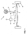
- FIG. 1 shows an electromechanical steering system 1 for a motor vehicle.
- the steering 1 comprises a steering wheel 2, via which a steering torque can be applied by a driver.
- This steering torque is transmitted from the steering wheel 2 via a steering column 3 to a steering gear 4.
- the steering gear 4 has a rack, which is coupled at its ends in each case via a hinge 5 with a tie rod 6.
- Each tie rod 6 engages a supported on the vehicle body wheel carrier 7, on which a vehicle wheel 8 is mounted.
- the steering torque is brought in the form of a steering force along the rack on the tie rods 6 and ultimately to the vehicle wheels 8 to action.
- an additional steering torque is introduced into the steering 1 to assist the driver when steering.
- This additional steering torque is generated in the illustrated steering 1 by an electric motor 9, which can be arranged, for example, axially parallel or coaxial with the rack. It is also possible to arrange the engine elsewhere or to provide a force attack on the steering column 3. For controlling the electric motor 9, this can be equipped with an engine position sensor, not shown.
- the additional steering torque is set as a function of the steering torque applied by the driver. This steering torque representing the driver's request can be detected, for example, via a steering torque sensor 10 on the steering column 3.
- the steering torque sensor 10 may comprise strain gauges, for example, which are applied to a torsion element incorporated into the steering column 3, for example a torsion bar.
- strain gauges for example, which are applied to a torsion element incorporated into the steering column 3, for example a torsion bar.
- other sensor principles can also be used.
- the signal of the steering torque sensor 10 represents the applied steering torque, but from which, if necessary, again an angular dimension can be calculated.
- the output signal of the steering torque sensor 10 is applied to a device 11 for evaluating the signal waveform.
- a device 11 for evaluating the signal waveform In this an algorithm for the conclusion of a fatigue state of the driver is stored. If such a state of fatigue is detected, a warning signal can be generated and displayed to the driver.
- the steering torque sensor 10 can be used in particular algorithms, which on the evaluation of a measured Steering angle velocity based.
- the steering torque can replace the steering angle as an input signal in the algorithm.
- the driver's fatigue condition when the waveform remains within a predetermined bandwidth tolerance band in a predetermined time interval that is only a fraction of a second.
- a predetermined time interval that is only a fraction of a second.
- several such time intervals can be evaluated.
- the means 11 for evaluating the waveform is preferably included in a steering controller.
- the signal of the steering torque sensor 10 is interpreted as a rotation angle.
- This can be summed up with a steering angle calculated in the steering control unit 12, which is provided, for example, to an electronic stability program.
- the sum signal then forms the input signal of the device 11 for evaluating the signal profile, as shown in FIG FIG. 2 is shown.
- the torsion or rotation of the measuring element can be determined via a calibration of the measured electrical voltage with respect to the angle of rotation. This makes it possible to determine the steering angle from the sum of the calculated steering angle of the electromechanical steering and the torsion of the measuring element.
- the position of the rack or the tie rods 6 correlated with the position of the vehicle wheels 8, but in an acting on the rack or on the steering column 3 and equipped with a Motoriagesensor electric motor 9 by means of the signals of the motor position sensor, the position of the rack and thus the angle of the steered vehicle wheels 8 and - directly or indirectly by means of the output signal of the steering torque sensor - and the steering angle are calculated on the steering wheel. Likewise, of course, the corresponding steering angle velocity can also be calculated.
- the idle state via the steering torque sensor and the breaking be detected from the idle state via the calculated for example by means of the motor position sensor steering angle or Lenkwinkei educaen.
- both the observation of the steering angle and the steering wheel speed are suitable for the invention for detecting a fatigue state of a driver in addition to the waveform of the steering torque sensor.
Abstract
Description
Die Erfindung bezieht sich auf ein Verfahren zur Erkennung eines Ermüdungszustands eines Fahrers eines Kraftfahrzeugs. Weiterhin bezieht sich die Erfindung auf eine entsprechende Vorrichtung.The invention relates to a method for detecting a fatigue state of a driver of a motor vehicle. Furthermore, the invention relates to a corresponding device.
Verfahren und Vorrichtungen zur Erkennung eines Ermüdungszustands eines Fahrers eines Kraftfahrzeugs sind beispielsweise aus der
Unfallstatistiken zeigen, dass ein hoher Anteil schwerer Unfälle auf das Einschlafen des Fahrers am Lenkrad zurückzuführen ist. Aus dem Lenkverhalten ist es möglich, die Müdigkeit des Fahrers zu erkennen. Normalerweise zeigt der Fahrer ein unbewusstes Regelverhalten, bei dem er ständig die Lenkung korrigiert. Wird der Fahrer zunehmend müde, setzt dieses Regelverhalten aus und er hält das Lenkrad zunehmend starr und korrigiert dann schnell (sogenannter Dead-Band-Event). Zum Erkennen des Ermüdungszustands werden demzufolge Erelgnisse gesucht, bei denen auf eine Ruhephase eine Korrekturphase folgt. Durch eine geeignete Überwachung der Betätigung der Lenkung kann eine Ermüdung des Fahrers erkannt und der Fahrer durch geeignete Maßnahmen zu einer erhöhten Aufmerksamkeit angeregt oder gewarnt werden.Accident statistics show that a high proportion of serious accidents is due to the driver falling asleep on the steering wheel. From the steering behavior it is possible to detect the tiredness of the driver. Normally, the driver shows an unconscious control behavior, in which he constantly corrects the steering. If the driver becomes increasingly tired, this control behavior stops and he keeps the steering wheel increasingly rigid and then corrects quickly (so-called dead band event). Accordingly, to detect the state of fatigue, findings are sought in which a rest phase is followed by a correction phase. By a suitable monitoring of the operation of the steering, fatigue of the driver can be detected and the driver can be stimulated or warned by appropriate measures to increased attention.
Gemäß der
Aus der
In der
Es ist aber ebenfalls möglich, z.B. aus Kostengründen auf einen Lenkwinkelsensor am Lenkrad zu verzichten und seine Funktion durch eine rechnerische Abschätzung des Lenkwinkels zu ersetzen, In diesem Fall ist es erforderlich, für das ESP benötigte Lenkwinkel im Steuergerät der Lenkung anhand anderer Informationen zu berechnen.However, it is also possible, e.g. For reasons of cost, to dispense with a steering angle sensor on the steering wheel and to replace its function by a mathematical estimation of the steering angle, in this case, it is necessary to calculate the steering angle required for the ESP in the control unit of the steering using other information.
Zwischen dem Lenkrad und dem Lenkgetriebe einer Lenkung Ist In der Regel ein Lenkmomentsensor zur Erfassung des Fahrerwunsches vorgesehen, der üblicherweise die Verdrehung eines im Bereich der Lenksäule oder -welle vorgesehenen Torsionsstabs erfasst. Das Signal des Lenkmomentsensors wird bei der Regelung der Lenkunterstützung, respektive der Lenkhilfskraft bzw. des Lenkhilfsmoments, berücksichtigt.Between the steering wheel and the steering gear of a steering system is usually provided a steering torque sensor for detecting the driver's request, which usually detects the rotation of a provided in the region of the steering column or shaft torsion bar. The signal of the steering torque sensor is taken into account in the regulation of the steering assistance, respectively the steering assist force or the steering assist torque.
Bei einem Entfall des Lenkwinkelsensors am Lenkrad könnte für die Erkennung des Ermüdungszustands der im Steuergerät berechnete Lenkwinkel herangezogen werden. Eine solche Vorgehensweise liefert Jedoch nicht immer zufriedenstellende Ergebnisse. Da das Lenkrad und die Lenkung nicht starr miteinander gekoppelt sind, sondern, wie angegeben, unter anderem zur Ermittlung des Lenkmoments ein Torsionsstab in der Lenksäule zwischen dem Lenkrad und dem Lenkgetriebe eingekoppelt ist, weicht der berechnete Lenkwinkel von dem tatsächlichen Winkel am Lenkrad ab. Die Elastizitäten der Lenkung wirken zudem wie ein Tiefpassfilter, so dass für die Erkennung des Ermüdungszustands relevante Frequenzen weitgehend außerhalb des Beobachtungsbereichs liegen. Ohne einen mit dem Lenkrad gekoppelten Lenkwinkelsensor ist in einem solchen Fall die Lenktätigkeit des Fahrers nicht mit der für die Ermüdungserkennung erforderlichen Auflösung messbar.If there is no steering angle sensor on the steering wheel, the steering angle calculated in the control unit could be used to detect the state of fatigue. However, such a procedure does not always provide satisfactory results. Since the steering wheel and the steering are not rigidly coupled to each other, but, as stated, inter alia, for determining the steering torque, a torsion bar in the steering column between the steering wheel and the steering gear is coupled, deviates the calculated steering angle of the actual angle on the steering wheel. The elasticities of the steering also act as a low-pass filter, so that relevant for the detection of fatigue state frequencies are largely outside the observation area. Without a steering angle sensor coupled to the steering wheel, the steering operation of the driver can not be measured with the resolution required for fatigue detection in such a case.
Der Erfindung liegt die Aufgabe zugrunde, hier Abhilfe zu schaffen. Insbesondere zielt die Erfindung darauf ab, auch ohne einen Lenkwinkelsensor am Lenkrad eine schnelle und zuverlässige Ermüdungserkennung eines Fahrers zu realisieren.The invention has for its object to remedy this situation. In particular, the invention aims, even without a steering angle sensor on the steering wheel to realize a fast and reliable fatigue detection of a driver.
Diese Aufgabe wird durch ein Verfahren gemäß Patentanspruch 1 sowie alternativ Patentanspruch 2 bzw. durch eine Vorrichtung gemäß Patentanspruch 9 sowie alternativ Patentanspruch 10 gelöst.This object is achieved by a method according to claim 1 and alternatively claim 2 or by a device according to
Der Verlauf des vom Fahrer aufgebrachten Lenkmoments korreliert stark mit der Lenkwinkelgeschwindigkeit am Lenkrad, so dass aus dem Verlauf eines das Lenkmoment repräsentierenden Signals auf den Ermüdungszustand des Fahrers geschlossen werden kann. Die Auswertung des Signalverlaufs kann dabei mit an sich bekannten Algorithmen erfolgen. Beispielsweise können hierzu die in der
Das Signal des Lenkmomentsensors Ist beispielsweise eine Weg- oder Winkelgröße, welche die Dehnung eines Torsionsstabs oder die Relativverdrehung zwischen einer über einen Torsionsstab gekoppelten Eingangs- und Ausgangswelle repräsentiert. Da die Elastizität des Torsionsstabs bekannt ist, entspricht die Weg- bzw. Winkelgröße dem zu erfassenden Moment.The signal of the steering torque sensor is, for example, a path or angular size, which represents the expansion of a torsion bar or the relative rotation between a coupled via a torsion bar input and output shaft. Since the elasticity of the torsion bar is known, the path or angle size corresponds to the moment to be detected.
Für eine sichere schnelle und genaue Erfassung des Ermüdungszustands des Fahrers, insbesondere schneller Korrekturbewegungen des Fahrers am Lenkrad am Ende eines Dead-Band-Events, wird aus dem Ausgangssignal des Lenkmomentsensors und einem Signal, welches einen berechneten Lenkwinkel oder eine berechnete Lenkwinkelgeschwindigkeit repräsentiert, ein Summensignal erzeugt und aus dessen Verlauf auf den Ermüdungszustand des Fahrers geschlossen.For a sure fast and accurate detection of the fatigue state of the driver, in particular quick correction of the driver on the steering wheel at the end of a dead band event, from the output of the steering torque sensor and a signal representing a calculated steering angle or a calculated steering angular velocity, a sum signal generated and closed from the course of the driver's state of fatigue.
Aus dem gleichen Grund ist es ebenfalls vorteilhaft, wenn der zeitliche Verlauf des Ausgangssignals des Lenkmomentsensors und eines Signals, welches einen berechneten Lenkwinkel oder eine berechnete Lenkwinkelgeschwindigkeit repräsentiert, verglichen und aus diesem Verlauf der beiden Signale auf den Ermüdungszustand des Fahrers geschlossen wird.For the same reason, it is also advantageous if the time course of the output signal of the steering torque sensor and a signal representing a calculated steering angle or a calculated steering angular velocity, compared and concluded from this course of the two signals on the driver's fatigue state.
Vorteilhafte Ausgestaltungen und Verbesserungen sind in abhängigen Patentansprüchen angegeben.Advantageous embodiments and improvements are specified in the dependent claims.
Für eine einfache Bildung eines Summensignals bzw. für einen einfachen Vergleich des Ausgangssignals des Lenkmomentsensors und eines Signals, welches einen berechneten Lenkwinkel oder eine berechnete Lenkwinkeigeschwindigkeit repräsentiert, ist es von Vorteil, wenn das Ausgangssignal des Lenkmomentsensors als Drehwinkel und/oder Drehwinkelgeschwindigkeit Interpretiert wird.For a simple formation of a sum signal or for a simple comparison of the output signal of the steering torque sensor and a signal representing a calculated steering angle or a calculated Lenkwinkeigeschwindigkeit, it is advantageous if the output of the steering torque sensor is interpreted as rotation angle and / or rotational angular velocity.
Für eine zuverlässige Erfassung des Ermüdungszustands des Fahrers ist es zudem von Vorteil, wenn auf einen Ermüdungszustand des Fahrers geschlossen wird, wenn der Signalverlauf über ein oder mehrere vorgegebene Zeitintervalle innerhalb eines Toleranzbandes mit vorgegebener Bandbreite bleibt.For a reliable detection of the fatigue state of the driver, it is also advantageous if it is concluded that the driver is in a state of fatigue if the signal course remains within a tolerance band with a predetermined bandwidth over one or more predetermined time intervals.
Bei Verzicht auf einen mit dem Lenkrad gekoppelten Lenkwinkelsensor Ist es zur einfachen Ermittlung von Lenkwinkel und/oder Lenkwinkelgeschwindigkeit von Vorteil, wenn ein Signal eines Motorlagesensors eines der elektrischen Lenkhllfeunterstützung dienenden Elektromotors erfasst wird. Dabei ist es von Vorteil, wenn aus dem Signal des Motorlagesensors der Lenkwinkel und/oder die Lenkwinkelgeschwindigkeit an den gelenkten Fahrzeugrädern bzw. der Lenkwinkel und/oder die Lenkwinkelgeschwindigkeit des Fahrers am Lenkrad berechnet wird.In the absence of a steering angle sensor coupled to the steering wheel, it is advantageous for the simple determination of steering angle and / or steering angle speed when a signal of a motor position sensor of an electric steering assisting electric motor is detected. It is advantageous if the steering angle and / or the steering angle speed at the steered vehicle wheels or the steering angle and / or the steering angle speed of the driver on the steering wheel is calculated from the signal of the motor position sensor.
Zur einfachen Ermittlung des vom Fahrer aufgebrachten Lenkmoments ist es vorteilhaft, wenn der Lenkmomentsensor eine Torsion einer Lenksäule mittels Dehnungsmessstreifen oder mittels eines Drehwinkelgebers erfasst.For easy determination of the steering torque applied by the driver, it is advantageous if the steering torque sensor detects a torsion of a steering column by means of strain gauges or by means of a rotary encoder.
Nachfolgend wird die Erfindung anhand eines In der Zeichnung dargestellten Ausführungsbeispiels näher erläutert. Die Zeichnung zeigt in:
- Figur 1
- eine schematische Ansicht einer Vorrichtung zur Erkennung eines Ermüdungszustands eines Fahrers eines Kraftfahrzeugs nach einem ersten Ausführungsbeispiel der Erfindung.
Figur 2- eine schematische Ansicht einer Vorrichtung zur Erkennung eines Ermüdungszustands eines Fahrers eines Kraftfahrzeugs nach einem zweiten Ausführungsbeispiel der Erfindung.
- FIG. 1
- a schematic view of a device for detecting a fatigue state of a driver of a motor vehicle according to a first embodiment of the invention.
- FIG. 2
- a schematic view of a device for detecting a fatigue state of a driver of a motor vehicle according to a second embodiment of the invention.
Das Ausführungsbeispiel in
An geeigneter Stelle, bei dem Ausführungsbeispiel an dem Lenkgetriebe 4, wird ein Zusatzlenkmoment in die Lenkung 1 eingeleitet, um den Fahrer beim Lenken zu unterstützen. Dieses Zusatzlenkmoment wird bei der dargestellten Lenkung 1 durch einen Elektromotor 9 erzeugt, der beispielsweise achsparallel oder koaxial zu der Zahnstange angeordnet werden kann. Es ist auch möglich, den Motor an anderer Stelle anzuordnen oder einen Kraftangriff an der Lenksäule 3 vorzusehen. Zur Regelung des Elektromotors 9 kann dieser mit einem nicht dargestellten Motorlagesensor ausgestattet sein. Das Zusatzlenkmoment wird in Abhängigkeit des vom Fahrer aufgebrachten Lenkmoments eingestellt. Dieses den Fahrerwunsch repräsentierende Lenkmoment kann beispielsweise über einen Lenkmomentsensor 10 an der Lenksäule 3 erfasst werden.At an appropriate point, in the embodiment of the
Aus dem Lenkverhalten eines Fahrers kann auf einen Ermüdungszustande des Fahrers geschlossen werden. Normalerweise zeigt der Fahrer ein unbewusstes Regelverhalten, bei dem er ständig die Lenkung korrigiert. Wird der Fahrer zunehmend müde, setzt dieses Regelverhalten aus und er hält das Lenkrad zunächst starr und korrigiert dann schnell. Dieses Verhalten wird als Dead-Band-Event bezeichnet. Ziel ist es, diese Ereignisse, bei denen auf eine Ruhephase eine Korrekturphase mit deutlichen Abweichungen z.B. der Lenkwinkelgeschwindigkeit aus dem üblichen Korrekturbereich folgt, Im Lenkverhalten zu detektieren, wobei eine Häufung solcher Ereignisse auf eine zunehmende Müdigkeit hindeutet.From the steering behavior of a driver can be concluded on a state of fatigue of the driver. Normally, the driver shows an unconscious control behavior, in which he constantly corrects the steering. If the driver becomes increasingly tired, this control behavior stops and he keeps the steering wheel rigid at first and then corrects quickly. This behavior is called a dead band event. The aim is to avoid these events, where a rest phase is followed by a correction phase with significant deviations, e.g. The steering angle velocity from the usual correction range follows to detect in the steering behavior, with an accumulation of such events indicating an increasing fatigue.
Erfindungsgemäß wird aus dem Signal des Lenkmomentsensors 10 auf einen Ermüdungszustand des Fahrers geschlossen. Der Lenkmomentsensor 10 kann beispielsweise Dehnungsmessstreifen aufweisen, die an einem in die Lenksäule 3 eingegliederten Torsionselement, beispielsweise einem Torsionsstab, appliziert sind. Jedoch können auch andere Sensorprinzipien zum Einsatz kommen. Insbesondere ist es möglich, einen Verdrehwinkel zwischen den Enden eines Torsionsstabs zu messen. In sämtlichen Fällen repräsentiert das Signal des Lenkmomentsensors 10 das anliegende Lenkmoment, aus dem aber, sofern erforderlich, wiederum ein Winkelmaß berechnet werden kann.According to the invention, it is concluded from the signal of the
Das Ausgangssignal des Lenkmomentsensors 10 ist an eine Einrichtung 11 zum Auswerten des Signalverlaufs angelegt. In dieser ist ein Algorithmus zum Rückschluss auf einen Ermüdungszustand des Fahrers abgelegt. Wird, ein solcher Ermüdungszustand festgestellt, kann ein Warnsignal generiert und dem Fahrer zur Anzeige gebracht werden.The output signal of the
Bei der Auswertung des SIgnalverlaufs des Lenkmomentsensors 10 kann insbesondere auf Algorithmen zurückgegriffen werden, welche auf der Auswertung einer gemessenen Lenkwinkelgeschwindigkeit basieren. Dabei kann das Lenkmoment den Lenkwinkel als Eingangssignal im Algorithmus ersetzen.In the evaluation of the SIgnalverlaufs the
Beispielsweise ist es möglich, auf das Vorliegen eines Ermüdungszustands des Fahrers dann zu schließen, wenn der Signalverlauf in einem vorgegebenen Zeitintervall, das lediglich einen Bruchteil einer Sekunde beträgt, innerhalb eines Toleranzbandes mit vorgegebener Bandbreite bleibt. Gegebenenfalls können auch mehrere solcher Zeitintervalle ausgewertet werden.For example, it is possible to infer the driver's fatigue condition when the waveform remains within a predetermined bandwidth tolerance band in a predetermined time interval that is only a fraction of a second. Optionally, several such time intervals can be evaluated.
Die Einrichtung 11 zum Auswerten des Signalverlaufs wird vorzugsweise in einem Lenkungssteuergerät mituntergebracht.The means 11 for evaluating the waveform is preferably included in a steering controller.
In einer Abwandlung des vorstehend erläuterten Ausführungsbeispiels wird das Signal des Lenkmomentsensors 10 als Drehwinkel interpretiert. Dieser kann mit einem im Lenkungssteuergerät 12 berechneten Lenkwinkel, der beispielsweise einem elektronischen Stabilitätsprogramm zur Verfügung gestellt wird, summiert werden. Das Summensignal bildet dann das Eingangssignal der Einrichtung 11 zum Auswerten des Signalverlaufs, wie dies in
Da die Lage der Zahnstange bzw. der Spurstangen 6 mit der Stellung der Fahrzeugräder 8 korreliert, kann aber bei einem auf die Zahnstange bzw. auf die Lenksäule 3 wirkenden und mit einem Motoriagesensor ausgestatteten Elektromotor 9 mittels der Signale des Motorlagesensors die Stellung der Zahnstange und damit der Winkel der gelenkten Fahrzeugräder 8 und - direkt oder indirekt mit Hilfe des Ausgangssignals des Lenkmomentsensors - auch der Lenkwinkel am Lenkrad berechnet werden. Ebenso lässt sich selbstverständlich auch die entsprechende Lenkwinkelgeschwindigkeit berechnen.Since the position of the rack or the
Alternativ ist es zum Erhalt von weiteren Informationen möglich, dass der zeitliche Verlauf des Ausgangssignals des Lenkmomentsensors (10) und eines Signals, welches einen berechneten Lenkwinkel oder eine berechnete Lenkwinkelgeschwindigkeit repräsentiert, verglichen und aus diesem Verlauf der beiden Signale, also der zeitlichen Abfolge eines hohen Moments gefolgt von einem hohen berechneten Lenkwinkel oder einer hohen berechneten Lenkwinkelgeschwindigkeit, auf den Ermüdungszustand des Fahrers geschlossen wird. So können vorteilhafterweise der Ruhezustand über den Lenkmomentsensor und das Ausbrechen aus dem Ruhezustand über die z.B. mittels des Motorlagesensors errechneten Lenkwinkel oder Lenkwinkeigeschwindigkeiten erfasst werden.Alternatively, it is possible to obtain further information that the time course of the output signal of the steering torque sensor (10) and a signal representing a calculated steering angle or a calculated steering angular velocity compared and from this course of the two signals, ie the time sequence of a high Moments followed by a high calculated steering angle or a high calculated steering angle speed, the driver's state of fatigue is concluded. Thus, advantageously, the idle state via the steering torque sensor and the breaking be detected from the idle state via the calculated for example by means of the motor position sensor steering angle or Lenkwinkeigeschwindigkeiten.
Grundsätzlich sind für die Erfindung zum Erkennen eines Ermüdungszustands eines Fahrers neben dem Signalverlauf des Lenkmomentsensors sowohl die Betrachtung des Lenkwinkels als auch der Lenkwhkelgeschwindigkeit geeignet.Basically, both the observation of the steering angle and the steering wheel speed are suitable for the invention for detecting a fatigue state of a driver in addition to the waveform of the steering torque sensor.
- 11
- elektromechanische LenkungElectric Power Steering
- 22
- Lenkradsteering wheel
- 33
- Lenksäulesteering column
- 4.4th
- Lenkgetriebesteering gear
- 55
- SpurstangengelenkTie joint
- 66
- Spurstangetie rod
- 77
- Radträgerwheel carrier
- 88th
- Fahrzeugradvehicle
- 99
- Elektromotorelectric motor
- 1010
- LenkmomentsensorSteering torque sensor
- 1111
- Auswertungsmittelevaluating means
- 1212
- Lenkungssteuergerät .Steering control unit.
Claims (12)
- Method for detecting a tiredness state of a driver of a motor vehicle, characterized in that- an output signal of a steering torque sensor (10) is acquired,- a signal which represents a steering angle or a steering angle speed is calculated,- the output signal and the signal which represents a steering angle or a steering angle speed are summed in order to generate a sum signal, and- a tiredness state of the driver is inferred from the signal profile of the sum signal.
- Method for detecting a tiredness state of a driver of a motor vehicle, characterized in that- an output signal of a steering torque sensor (10) is acquired,- a signal which represents a steering angle or a steering angle speed is calculated,- the time profile of the output signal of the steering torque sensor (10) and that of the signal which represents the calculated steering angle or the calculated steering angle speed are compared, and- the tiredness state of the driver is inferred from the profile of the two signals.
- Method according to Claim 1 or 2, characterized in that the output signal of the steering torque sensor (10) is interpreted as a rotational angle and/or rotational angle speed.
- Method according to one of Claims 1 to 3, characterized in that a tiredness state of the driver is inferred if the signal profile remains within a tolerance range with a predefined bandwidth over one or more predefined time intervals.
- Method according to one of Claims 1 to 4, characterized in that the steering angle signal is calculated in a steering control unit (12).
- Method according to one of Claims 1 to 5, characterized in that a signal of a motor position sensor of an electric motor (9) which serves to provide electrical steering assistance is acquired.
- Method according to Claim 6, characterized in that the steering angle and/or the steering angle speed at the steered vehicle wheels (8) and/or the steering angle and/or the steering angle speed of the driver at the steering wheel (2) are/is calculated from the signal of the motor position sensor.
- Method according to one of Claims 1 to 7, characterized in that the steering torque sensor (10) acquires a torsion of a steering column (3) by means of strain gauges or by means of a rotational angle signal generator.
- Device for detecting a tiredness state of a driver of a motor vehicle, comprising:- a steering torque sensor (10) for acquiring a torsion torque applied to a steering column (3) and for generating a signal which represents said torsion torque, and- a steering control unit (12) which is configured to calculate a steering angle or a steering angle speed and to generate a representative signal, wherein the calculated steering angle or the calculated steering angle speed and the signal of the steering torque sensor (10) are summed to form a sum signal and the sum signal which results therefrom is applied as an input signal to the evaluation means (11),- evaluation means (11) for evaluating the signal profile of the sum signal applied as an input signal to the evaluation means on the basis of an algorithm for determining a tiredness state of the driver.
- Device for detecting a tiredness state of a driver of a motor vehicle, comprising:- a steering torque sensor (10) for acquiring a torsion torque applied to a steering column (3) and for generating a signal which represents said torsion torque, and- a steering control unit (12) which is configured to calculate a steering angle or a steering angle speed and to generate a representative signal, and- evaluation means (11) for evaluating the signal profile on the basis of an algorithm, for determining a tiredness state of the driver, wherein the time profile of the output signal of the steering torque sensor (10) and that of the signal which represents the calculated steering angle or the calculated steering angle speed are compared.
- Device according to Claim 9 or 10, characterized in that the steering torque sensor (10) is a rotational angle signal generator or has strain gauges.
- Device according to one of Claims 9 to 11, characterized in that a motor position sensor of an electric motor which serves to provide electrical steering assistance and which serves to detect the steering angle or the steering angle speed is provided.
Priority Applications (1)
| Application Number | Priority Date | Filing Date | Title |
|---|---|---|---|
| PL08009171T PL1997666T3 (en) | 2007-06-01 | 2008-05-19 | Method and device for recognizing a tiredness condition of a car driver |
Applications Claiming Priority (1)
| Application Number | Priority Date | Filing Date | Title |
|---|---|---|---|
| DE102007025643A DE102007025643A1 (en) | 2007-06-01 | 2007-06-01 | Method and device for detecting a state of fatigue of a driver of a motor vehicle |
Publications (2)
| Publication Number | Publication Date |
|---|---|
| EP1997666A1 EP1997666A1 (en) | 2008-12-03 |
| EP1997666B1 true EP1997666B1 (en) | 2010-11-03 |
Family
ID=39521963
Family Applications (1)
| Application Number | Title | Priority Date | Filing Date |
|---|---|---|---|
| EP08009171A Active EP1997666B1 (en) | 2007-06-01 | 2008-05-19 | Method and device for recognizing a tiredness condition of a car driver |
Country Status (4)
| Country | Link |
|---|---|
| EP (1) | EP1997666B1 (en) |
| AT (1) | ATE486741T1 (en) |
| DE (2) | DE102007025643A1 (en) |
| PL (1) | PL1997666T3 (en) |
Families Citing this family (9)
| Publication number | Priority date | Publication date | Assignee | Title |
|---|---|---|---|---|
| DE102010034599A1 (en) | 2010-08-16 | 2012-02-16 | Hooshiar Mahdjour | Method for recognition of tiredness of driver of vehicle, involves indicating tiredness of the driver, if difference between normative data and current data is exceeds threshold value |
| DE102010039949A1 (en) | 2010-08-30 | 2012-03-01 | Bayerische Motoren Werke Aktiengesellschaft | Method for detecting missing driver activity on the steering wheel of a motor vehicle |
| DE102014008791A1 (en) | 2014-06-11 | 2015-12-17 | Frank Munser-Herzog | Driver assistance system and method for detection of fatigue and microsleep avoidance of a driver |
| DE202014004917U1 (en) | 2014-06-11 | 2014-07-14 | Frank Munser-Herzog | Driver assistance system for detecting fatigue and avoiding the sleep of a driver |
| FR3028827B1 (en) * | 2014-11-20 | 2018-03-09 | Renault S.A.S. | METHOD FOR DETECTING THE LOSS OF VIGILANCE OF A VEHICLE DRIVER |
| CN108169015B (en) * | 2017-12-01 | 2020-06-09 | 中国直升机设计研究所 | Tail rotor flexible beam torque loading test device |
| DE102018204409A1 (en) * | 2018-03-22 | 2019-09-26 | Volkswagen Aktiengesellschaft | A method of displaying vehicle information and display system information |
| DE102018220612A1 (en) | 2018-11-29 | 2020-06-04 | Audi Ag | Steering wheel angle estimation method |
| CN109823345B (en) * | 2019-04-03 | 2023-04-18 | 吉林大学 | Safe driving system based on physiological information |
Family Cites Families (7)
| Publication number | Priority date | Publication date | Assignee | Title |
|---|---|---|---|---|
| SE0002804D0 (en) * | 2000-08-01 | 2000-08-01 | Promind Ab | Technology for continuously mapping the behavior / behavior of the vehicle / driver to determine the reaction coefficient of the vehicle or the vehicle. driver's skill coefficient, and device for graphical presentation of these coefficients |
| JP2003016959A (en) * | 2001-07-02 | 2003-01-17 | Hitachi Ltd | Color cathode-ray tube |
| DE10156509B4 (en) | 2001-11-16 | 2007-12-06 | Audi Ag | Driver assistance system |
| DE102004029825A1 (en) | 2004-06-19 | 2006-01-05 | Daimlerchrysler Ag | Method and device for detecting fatigue in the driver of a vehicle |
| DE102004047861A1 (en) | 2004-10-01 | 2006-04-06 | Daimlerchrysler Ag | Method and device for assisting the driver of a vehicle in the maintenance of a traffic lane |
| DE102005001230A1 (en) | 2005-01-11 | 2006-07-20 | Robert Bosch Gmbh | Driver`s state detecting method for vehicle, involves determining temperature of e.g. finger, comparing temperature with given threshold value and determining drowsiness or sleepiness of driver when temperature exceeds threshold value |
| DE102005026456B4 (en) | 2005-06-09 | 2017-04-20 | Daimler Ag | Method for detecting fatigue |
-
2007
- 2007-06-01 DE DE102007025643A patent/DE102007025643A1/en active Pending
-
2008
- 2008-05-19 PL PL08009171T patent/PL1997666T3/en unknown
- 2008-05-19 DE DE502008001687T patent/DE502008001687D1/en active Active
- 2008-05-19 AT AT08009171T patent/ATE486741T1/en active
- 2008-05-19 EP EP08009171A patent/EP1997666B1/en active Active
Also Published As
| Publication number | Publication date |
|---|---|
| EP1997666A1 (en) | 2008-12-03 |
| PL1997666T3 (en) | 2011-04-29 |
| DE102007025643A1 (en) | 2008-12-04 |
| ATE486741T1 (en) | 2010-11-15 |
| DE502008001687D1 (en) | 2010-12-16 |
Similar Documents
| Publication | Publication Date | Title |
|---|---|---|
| EP1997666B1 (en) | Method and device for recognizing a tiredness condition of a car driver | |
| DE102007027039B4 (en) | Determination of the absolute position of a steering system by a linear sensor on the rack | |
| WO2017186564A1 (en) | Hands-on/-off detection in a steer-by-wire system | |
| DE102011002997A1 (en) | Method for detecting a hands-free driving situation of a motor vehicle | |
| DE102009020157B4 (en) | Method and device for calculating a virtual rotor angle | |
| WO2017102375A1 (en) | Method for monitoring the status of an electronic power steering device or of at least one component of the electronic power steering device of a motor vehicle. | |
| DE10206474B4 (en) | Method and device for detecting the friction in an electrical or electromechanical steering device of a motor vehicle | |
| EP1536971B1 (en) | Method and device for recognizing the level of awareness of a vehicle driver | |
| DE102009026497A1 (en) | Method for detecting internal friction in a steering system | |
| EP2393702B1 (en) | Method and device for operating a steering arrangement of a motor vehicle | |
| DE102013218721B4 (en) | Method for reducing steering torque of a steering of a motor vehicle | |
| EP2544935B1 (en) | Method and device for detecting a deviation of a rotation rate signal of a rotation rate sensor | |
| EP1970289B1 (en) | Method for operating an electric power steering system | |
| DE19720440A1 (en) | Fault diagnostic monitoring e.g. for road FWD vehicle control system | |
| WO2020127265A1 (en) | Method for determining a steering sensation of a steer-by-wire steering system | |
| DE102009047323A1 (en) | Method for detecting fatigue state of driver while driving motor vehicle, involves completing active driver moment cycle based on comparison of active driver moment cycle with reference cycle or threshold value | |
| DE102012023463B4 (en) | Method and detection system for detecting a drop in air pressure in at least one vehicle tire, and a vehicle with such a detection system | |
| EP2228283B1 (en) | Method for recording whether a steering handle is held or not, method for operating a driver assistance system and motor vehicle | |
| DE102009011853B4 (en) | Electric power steering systems for vehicles with adjustable torsion bars | |
| EP2093093A2 (en) | Method and device for recognising missing driver activity on the steering wheel | |
| DE102010049431B4 (en) | Method for diagnosing at least one sensor unit to be diagnosed in an electromechanical steering system and electromechanical steering system | |
| DE102011105949A1 (en) | Method for fatigue- or attention evaluation of driver of vehicle during autonomous or semi-autonomous transverse guidance of vehicle, involves introducing driver to steering system of vehicle by torque | |
| DE102009019194A1 (en) | Method for detecting condition e.g. tiredness, of driver of motor vehicle, involves determining and evaluating duration of steering pause and number of steering pauses based on detected change of steering wheel angle | |
| DE102017213415B4 (en) | Method of operating a steering device | |
| WO2023011788A1 (en) | Method for monitoring a steering system |
Legal Events
| Date | Code | Title | Description |
|---|---|---|---|
| PUAI | Public reference made under article 153(3) epc to a published international application that has entered the european phase |
Free format text: ORIGINAL CODE: 0009012 |
|
| AK | Designated contracting states |
Kind code of ref document: A1 Designated state(s): AT BE BG CH CY CZ DE DK EE ES FI FR GB GR HR HU IE IS IT LI LT LU LV MC MT NL NO PL PT RO SE SI SK TR |
|
| AX | Request for extension of the european patent |
Extension state: AL BA MK RS |
|
| 17P | Request for examination filed |
Effective date: 20090603 |
|
| 17Q | First examination report despatched |
Effective date: 20090710 |
|
| AKX | Designation fees paid |
Designated state(s): AT BE BG CH CY CZ DE DK EE ES FI FR GB GR HR HU IE IS IT LI LT LU LV MC MT NL NO PL PT RO SE SI SK TR |
|
| GRAC | Information related to communication of intention to grant a patent modified |
Free format text: ORIGINAL CODE: EPIDOSCIGR1 |
|
| GRAP | Despatch of communication of intention to grant a patent |
Free format text: ORIGINAL CODE: EPIDOSNIGR1 |
|
| GRAS | Grant fee paid |
Free format text: ORIGINAL CODE: EPIDOSNIGR3 |
|
| GRAA | (expected) grant |
Free format text: ORIGINAL CODE: 0009210 |
|
| AK | Designated contracting states |
Kind code of ref document: B1 Designated state(s): AT BE BG CH CY CZ DE DK EE ES FI FR GB GR HR HU IE IS IT LI LT LU LV MC MT NL NO PL PT RO SE SI SK TR |
|
| REG | Reference to a national code |
Ref country code: GB Ref legal event code: FG4D Free format text: NOT ENGLISH |
|
| REG | Reference to a national code |
Ref country code: CH Ref legal event code: EP |
|
| REG | Reference to a national code |
Ref country code: IE Ref legal event code: FG4D Free format text: LANGUAGE OF EP DOCUMENT: GERMAN |
|
| REF | Corresponds to: |
Ref document number: 502008001687 Country of ref document: DE Date of ref document: 20101216 Kind code of ref document: P |
|
| REG | Reference to a national code |
Ref country code: NL Ref legal event code: VDEP Effective date: 20101103 |
|
| LTIE | Lt: invalidation of european patent or patent extension |
Effective date: 20101103 |
|
| PG25 | Lapsed in a contracting state [announced via postgrant information from national office to epo] |
Ref country code: LT Free format text: LAPSE BECAUSE OF FAILURE TO SUBMIT A TRANSLATION OF THE DESCRIPTION OR TO PAY THE FEE WITHIN THE PRESCRIBED TIME-LIMIT Effective date: 20101103 Ref country code: NO Free format text: LAPSE BECAUSE OF FAILURE TO SUBMIT A TRANSLATION OF THE DESCRIPTION OR TO PAY THE FEE WITHIN THE PRESCRIBED TIME-LIMIT Effective date: 20110203 |
|
| REG | Reference to a national code |
Ref country code: PL Ref legal event code: T3 |
|
| REG | Reference to a national code |
Ref country code: IE Ref legal event code: FD4D |
|
| PG25 | Lapsed in a contracting state [announced via postgrant information from national office to epo] |
Ref country code: HR Free format text: LAPSE BECAUSE OF FAILURE TO SUBMIT A TRANSLATION OF THE DESCRIPTION OR TO PAY THE FEE WITHIN THE PRESCRIBED TIME-LIMIT Effective date: 20101103 Ref country code: FI Free format text: LAPSE BECAUSE OF FAILURE TO SUBMIT A TRANSLATION OF THE DESCRIPTION OR TO PAY THE FEE WITHIN THE PRESCRIBED TIME-LIMIT Effective date: 20101103 Ref country code: IS Free format text: LAPSE BECAUSE OF FAILURE TO SUBMIT A TRANSLATION OF THE DESCRIPTION OR TO PAY THE FEE WITHIN THE PRESCRIBED TIME-LIMIT Effective date: 20110303 Ref country code: LV Free format text: LAPSE BECAUSE OF FAILURE TO SUBMIT A TRANSLATION OF THE DESCRIPTION OR TO PAY THE FEE WITHIN THE PRESCRIBED TIME-LIMIT Effective date: 20101103 Ref country code: BG Free format text: LAPSE BECAUSE OF FAILURE TO SUBMIT A TRANSLATION OF THE DESCRIPTION OR TO PAY THE FEE WITHIN THE PRESCRIBED TIME-LIMIT Effective date: 20110203 Ref country code: PT Free format text: LAPSE BECAUSE OF FAILURE TO SUBMIT A TRANSLATION OF THE DESCRIPTION OR TO PAY THE FEE WITHIN THE PRESCRIBED TIME-LIMIT Effective date: 20110303 Ref country code: SE Free format text: LAPSE BECAUSE OF FAILURE TO SUBMIT A TRANSLATION OF THE DESCRIPTION OR TO PAY THE FEE WITHIN THE PRESCRIBED TIME-LIMIT Effective date: 20101103 Ref country code: NL Free format text: LAPSE BECAUSE OF FAILURE TO SUBMIT A TRANSLATION OF THE DESCRIPTION OR TO PAY THE FEE WITHIN THE PRESCRIBED TIME-LIMIT Effective date: 20101103 Ref country code: SI Free format text: LAPSE BECAUSE OF FAILURE TO SUBMIT A TRANSLATION OF THE DESCRIPTION OR TO PAY THE FEE WITHIN THE PRESCRIBED TIME-LIMIT Effective date: 20101103 |
|
| PG25 | Lapsed in a contracting state [announced via postgrant information from national office to epo] |
Ref country code: GR Free format text: LAPSE BECAUSE OF FAILURE TO SUBMIT A TRANSLATION OF THE DESCRIPTION OR TO PAY THE FEE WITHIN THE PRESCRIBED TIME-LIMIT Effective date: 20110204 |
|
| PG25 | Lapsed in a contracting state [announced via postgrant information from national office to epo] |
Ref country code: CZ Free format text: LAPSE BECAUSE OF FAILURE TO SUBMIT A TRANSLATION OF THE DESCRIPTION OR TO PAY THE FEE WITHIN THE PRESCRIBED TIME-LIMIT Effective date: 20101103 Ref country code: EE Free format text: LAPSE BECAUSE OF FAILURE TO SUBMIT A TRANSLATION OF THE DESCRIPTION OR TO PAY THE FEE WITHIN THE PRESCRIBED TIME-LIMIT Effective date: 20101103 Ref country code: IE Free format text: LAPSE BECAUSE OF FAILURE TO SUBMIT A TRANSLATION OF THE DESCRIPTION OR TO PAY THE FEE WITHIN THE PRESCRIBED TIME-LIMIT Effective date: 20101103 Ref country code: ES Free format text: LAPSE BECAUSE OF FAILURE TO SUBMIT A TRANSLATION OF THE DESCRIPTION OR TO PAY THE FEE WITHIN THE PRESCRIBED TIME-LIMIT Effective date: 20110214 |
|
| PG25 | Lapsed in a contracting state [announced via postgrant information from national office to epo] |
Ref country code: RO Free format text: LAPSE BECAUSE OF FAILURE TO SUBMIT A TRANSLATION OF THE DESCRIPTION OR TO PAY THE FEE WITHIN THE PRESCRIBED TIME-LIMIT Effective date: 20101103 Ref country code: SK Free format text: LAPSE BECAUSE OF FAILURE TO SUBMIT A TRANSLATION OF THE DESCRIPTION OR TO PAY THE FEE WITHIN THE PRESCRIBED TIME-LIMIT Effective date: 20101103 Ref country code: DK Free format text: LAPSE BECAUSE OF FAILURE TO SUBMIT A TRANSLATION OF THE DESCRIPTION OR TO PAY THE FEE WITHIN THE PRESCRIBED TIME-LIMIT Effective date: 20101103 |
|
| PLBE | No opposition filed within time limit |
Free format text: ORIGINAL CODE: 0009261 |
|
| STAA | Information on the status of an ep patent application or granted ep patent |
Free format text: STATUS: NO OPPOSITION FILED WITHIN TIME LIMIT |
|
| 26N | No opposition filed |
Effective date: 20110804 |
|
| BERE | Be: lapsed |
Owner name: VOLKSWAGEN A.G. Effective date: 20110531 |
|
| REG | Reference to a national code |
Ref country code: DE Ref legal event code: R097 Ref document number: 502008001687 Country of ref document: DE Effective date: 20110804 |
|
| PG25 | Lapsed in a contracting state [announced via postgrant information from national office to epo] |
Ref country code: MT Free format text: LAPSE BECAUSE OF FAILURE TO SUBMIT A TRANSLATION OF THE DESCRIPTION OR TO PAY THE FEE WITHIN THE PRESCRIBED TIME-LIMIT Effective date: 20101103 Ref country code: IT Free format text: LAPSE BECAUSE OF FAILURE TO SUBMIT A TRANSLATION OF THE DESCRIPTION OR TO PAY THE FEE WITHIN THE PRESCRIBED TIME-LIMIT Effective date: 20101103 Ref country code: MC Free format text: LAPSE BECAUSE OF NON-PAYMENT OF DUE FEES Effective date: 20110531 |
|
| PG25 | Lapsed in a contracting state [announced via postgrant information from national office to epo] |
Ref country code: BE Free format text: LAPSE BECAUSE OF NON-PAYMENT OF DUE FEES Effective date: 20110531 |
|
| REG | Reference to a national code |
Ref country code: CH Ref legal event code: PL |
|
| PG25 | Lapsed in a contracting state [announced via postgrant information from national office to epo] |
Ref country code: LI Free format text: LAPSE BECAUSE OF NON-PAYMENT OF DUE FEES Effective date: 20120531 Ref country code: CH Free format text: LAPSE BECAUSE OF NON-PAYMENT OF DUE FEES Effective date: 20120531 |
|
| PG25 | Lapsed in a contracting state [announced via postgrant information from national office to epo] |
Ref country code: CY Free format text: LAPSE BECAUSE OF FAILURE TO SUBMIT A TRANSLATION OF THE DESCRIPTION OR TO PAY THE FEE WITHIN THE PRESCRIBED TIME-LIMIT Effective date: 20101103 Ref country code: LU Free format text: LAPSE BECAUSE OF NON-PAYMENT OF DUE FEES Effective date: 20110519 |
|
| PG25 | Lapsed in a contracting state [announced via postgrant information from national office to epo] |
Ref country code: TR Free format text: LAPSE BECAUSE OF FAILURE TO SUBMIT A TRANSLATION OF THE DESCRIPTION OR TO PAY THE FEE WITHIN THE PRESCRIBED TIME-LIMIT Effective date: 20101103 |
|
| PG25 | Lapsed in a contracting state [announced via postgrant information from national office to epo] |
Ref country code: HU Free format text: LAPSE BECAUSE OF FAILURE TO SUBMIT A TRANSLATION OF THE DESCRIPTION OR TO PAY THE FEE WITHIN THE PRESCRIBED TIME-LIMIT Effective date: 20101103 |
|
| REG | Reference to a national code |
Ref country code: AT Ref legal event code: MM01 Ref document number: 486741 Country of ref document: AT Kind code of ref document: T Effective date: 20130519 |
|
| PG25 | Lapsed in a contracting state [announced via postgrant information from national office to epo] |
Ref country code: AT Free format text: LAPSE BECAUSE OF NON-PAYMENT OF DUE FEES Effective date: 20130519 |
|
| REG | Reference to a national code |
Ref country code: FR Ref legal event code: PLFP Year of fee payment: 9 |
|
| REG | Reference to a national code |
Ref country code: FR Ref legal event code: PLFP Year of fee payment: 10 |
|
| REG | Reference to a national code |
Ref country code: FR Ref legal event code: PLFP Year of fee payment: 11 |
|
| P01 | Opt-out of the competence of the unified patent court (upc) registered |
Effective date: 20230523 |
|
| PGFP | Annual fee paid to national office [announced via postgrant information from national office to epo] |
Ref country code: FR Payment date: 20230523 Year of fee payment: 16 Ref country code: DE Payment date: 20230531 Year of fee payment: 16 |
|
| PGFP | Annual fee paid to national office [announced via postgrant information from national office to epo] |
Ref country code: PL Payment date: 20230511 Year of fee payment: 16 |
|
| PGFP | Annual fee paid to national office [announced via postgrant information from national office to epo] |
Ref country code: GB Payment date: 20230523 Year of fee payment: 16 |