EP1997452A2 - Vorrichtung zur sterilen Umhüllung eines sterilisationsempfindlichen Bedienteils - Google Patents
Vorrichtung zur sterilen Umhüllung eines sterilisationsempfindlichen Bedienteils Download PDFInfo
- Publication number
- EP1997452A2 EP1997452A2 EP08009824A EP08009824A EP1997452A2 EP 1997452 A2 EP1997452 A2 EP 1997452A2 EP 08009824 A EP08009824 A EP 08009824A EP 08009824 A EP08009824 A EP 08009824A EP 1997452 A2 EP1997452 A2 EP 1997452A2
- Authority
- EP
- European Patent Office
- Prior art keywords
- transfer station
- sterilization
- medical instrument
- handling element
- docking
- Prior art date
- Legal status (The legal status is an assumption and is not a legal conclusion. Google has not performed a legal analysis and makes no representation as to the accuracy of the status listed.)
- Granted
Links
- 238000004659 sterilization and disinfection Methods 0.000 title claims abstract description 56
- 238000012546 transfer Methods 0.000 claims abstract description 75
- 230000001954 sterilising effect Effects 0.000 claims abstract description 55
- 230000008878 coupling Effects 0.000 claims description 29
- 238000010168 coupling process Methods 0.000 claims description 29
- 238000005859 coupling reaction Methods 0.000 claims description 29
- 238000003032 molecular docking Methods 0.000 claims description 29
- 238000011477 surgical intervention Methods 0.000 claims description 3
- 239000003814 drug Substances 0.000 claims 1
- 239000011248 coating agent Substances 0.000 description 9
- 238000000576 coating method Methods 0.000 description 9
- 238000000034 method Methods 0.000 description 4
- 238000001356 surgical procedure Methods 0.000 description 4
- 238000011109 contamination Methods 0.000 description 3
- 230000005540 biological transmission Effects 0.000 description 2
- 238000013459 approach Methods 0.000 description 1
- 238000004140 cleaning Methods 0.000 description 1
- 238000005520 cutting process Methods 0.000 description 1
- 238000013461 design Methods 0.000 description 1
- 238000005516 engineering process Methods 0.000 description 1
- 238000011010 flushing procedure Methods 0.000 description 1
- 238000005286 illumination Methods 0.000 description 1
- 238000004519 manufacturing process Methods 0.000 description 1
- 239000013307 optical fiber Substances 0.000 description 1
- 238000004806 packaging method and process Methods 0.000 description 1
- 238000002360 preparation method Methods 0.000 description 1
- 238000012545 processing Methods 0.000 description 1
- 230000001681 protective effect Effects 0.000 description 1
- 238000004064 recycling Methods 0.000 description 1
Images


Classifications
-
- A—HUMAN NECESSITIES
- A61—MEDICAL OR VETERINARY SCIENCE; HYGIENE
- A61B—DIAGNOSIS; SURGERY; IDENTIFICATION
- A61B1/00—Instruments for performing medical examinations of the interior of cavities or tubes of the body by visual or photographical inspection, e.g. endoscopes; Illuminating arrangements therefor
- A61B1/00142—Instruments for performing medical examinations of the interior of cavities or tubes of the body by visual or photographical inspection, e.g. endoscopes; Illuminating arrangements therefor with means for preventing contamination, e.g. by using a sanitary sheath
-
- A—HUMAN NECESSITIES
- A61—MEDICAL OR VETERINARY SCIENCE; HYGIENE
- A61B—DIAGNOSIS; SURGERY; IDENTIFICATION
- A61B1/00—Instruments for performing medical examinations of the interior of cavities or tubes of the body by visual or photographical inspection, e.g. endoscopes; Illuminating arrangements therefor
- A61B1/00002—Operational features of endoscopes
- A61B1/00039—Operational features of endoscopes provided with input arrangements for the user
- A61B1/00042—Operational features of endoscopes provided with input arrangements for the user for mechanical operation
-
- A—HUMAN NECESSITIES
- A61—MEDICAL OR VETERINARY SCIENCE; HYGIENE
- A61B—DIAGNOSIS; SURGERY; IDENTIFICATION
- A61B46/00—Surgical drapes
- A61B46/10—Surgical drapes specially adapted for instruments, e.g. microscopes
Definitions
- the invention relates to a device for sterile enclosure of a sterilization-sensitive control unit, which is connectable for surgical intervention with a medical instrument, with a handling element having a collapsed sterile tube at a distal end, wherein the handling element further comprises an opening through which proximally to the distal end of the sterilization-sensitive control panel is inserted into the sterile tube, that while the sterilization-sensitive control panel with the sterile tube is umhüllbar.
- Such a device for the sterile enclosure of a sterilization-sensitive control unit is known from DE 39 20 508 A1 known.
- Such devices are used in surgical procedures in which equipment is used that is difficult or impossible to sterilize.
- Such sterilization-sensitive keypads include camera systems used in conjunction with the endoscopes for various surgical procedures.
- An endoscopic camera system includes a camera head having sensitive internal electronic components, e.g. a signal processing unit which processes the signals from image sensing optics into video signals suitable for being fed to a monitor.
- a signal processing unit which processes the signals from image sensing optics into video signals suitable for being fed to a monitor.
- Such a camera system is compared to a medical instrument, e.g. connected to an endoscope.
- a medical instrument e.g. connected to an endoscope.
- the surgeon can observe the surgical site on a monitor.
- the surgeon handles the assembly via a control panel of the camera system.
- Other control elements such as switches, taps, electrical plug-in systems, etc. may also be present on the control unit, via which additional instrumentation of the instrument, such as e.g. Suction and flushing lines can be operated.
- This control panel is sensitive to sterilization due to its complexity and sensitive components.
- the camera system and its connecting cable are coated with a sterile coating in the form of a tube before it is placed on the endoscope. After the procedure, the camera system is disconnected from the endoscope.
- the device known from the document mentioned has for this purpose a handling element in the form of a pickup on which a collapsed sterile coating is fixed.
- a control panel of a sterilization-sensitive camera is inserted through an opening in the receptacle so far into the receptacle until the camera is fixed in the receptacle.
- a sterile person opens an outer protective cover over which the transducer is coated, and the camera is grasped through the sterile cover by a hand of the surgeon and pulled away from the transducer.
- the camera and the camera cable are automatically wrapped with the sterile coating.
- the camera Before removing the camera from the pickup, the camera can be connected to a medical instrument.
- the sterile coating has an opening at its distal end.
- a proximal end of the medical instrument is inserted through the distal opening in the sterile coating into the interior of the coating where it is connected to a coupling element of the sterilization-sensitive camera.
- the invention is therefore the object of further developing a device for the sterile enclosure of a sterilization-sensitive control unit of the type mentioned in that the connection of the medical instrument with the sterilization-sensitive control panel and the wrapping of the sterilization-sensitive control panel easily, if possible even with one hand, be performed by a person can, without the risk of contamination of the sterilization-sensitive control panel is.
- the object is achieved in that a medical instrument at its proximal end portion with a distal end of the hose is firmly connected, and that a transfer station, in which the sterilization-sensitive control unit is received, is present, wherein the handling element with the transfer station is so connectable in that the medical instrument and the sterilization-sensitive operating part can be connected to one another, and that this assembly can be pulled off the transfer station, wherein the shirred tube can be pulled over the sterilization-sensitive operating part.
- the firm connection of the medical instrument to the distal end of the sterile tube connected to the handling element initially has the advantage that these three components can be prefabricated, assembled and sterilized as a compact sterile unit. Furthermore, the prefabricated unit has the considerable advantage that in a single step, both the medical instrument is connected to the sterilization-sensitive control unit, and the sterile tube is placed with respect to the transfer station such that the sterilization-sensitive control panel automatically when it is pulled out of the transfer station is wrapped with the hose.
- This step can be performed with one person's (sterile) hand from the sterile area without the risk of contaminating the sterile area or compromising the tubing. With the other (not necessarily sterile) hand, this person can previously prepare the transfer station.
- the sterilization-sensitive control panel is first fixed in the non-sterile area in the transfer station.
- the sterile assembly of handling element, tube and the medical instrument is brought by the person with one hand to the transfer station and connected to the transfer station.
- the medical instrument is connected to the recorded in the transfer station sterilization-sensitive control panel.
- the sterile medical instrument can now be grasped by the surgeon.
- the sterilization-sensitive control unit temporarily connected to it is pulled out of the transfer station and thereby automatically enveloped by the sterile tube.
- the medical instrument can be versatile. It may be an endoscope that performs pure observation function, it may also be additionally or exclusively a tool that is a working instrument. These include, for example, tools for tissue manipulation, such as drills or cutting elements. These can be powered by a motor. The drive or motor can be accommodated in the control panel.
- the handling element on the distal side on a handle in a further embodiment of the invention, the handling element on the distal side on a handle.
- This measure has the advantage that the handle of the docking operation of the unit at the transfer station can be carried out particularly safely and easily with a (sterile) hand.
- the handling element has a coupling on the proximal side.
- This measure has the advantage that the coupling, which is brought to the unsterilized transfer station to connect the handling element to the transfer station, from the sterile area, in which both the handle and the sterile tube and fixed with the hose connected medical instrument, is spatially separated. This further contributes to the fact that the sterile area is not contaminated.
- the handling element on a flat base part, projecting from the handle and the coupling.
- This measure has the advantage that the flat base part separates the handle and the clutch from each other. This helps to ensure that the surgeon does not accidentally seize the coupling.
- the base part prevents the hand that has grasped the handle from coming into contact with the transfer station.
- the sterile tube is attached to the handle.
- This measure has the advantage that the shirred tube can be mounted in a compact design.
- the handle is designed as an annular flange.
- This measure has the advantage that such a trained handle can be safely held by a surgeon. This ensures that the handling element with the sterile tube and the medical instrument when attaching it to the transfer station does not fall out of the hand of the surgeon.
- the coupling has a coupling element.
- This measure has the advantage that the handling element can be connected to the transfer station in a simple and targeted manner.
- the coupling is designed as a bayonet coupling.
- the coupling element on the handling element can be formed as a pin, which can be accomplished by a manufacturing technology extremely simple operation.
- a bayonet guide at the transfer station can be accomplished by a simple Einfräsvorgang.
- the base part of the handling element has an orientation feature.
- This measure has the advantage that, by providing the orientation feature on the base part, the surgeon can particularly easily recognize in which position the handling element has to be brought to the transfer station for docking.
- the handling element and the hose are designed as disposable elements.
- This measure has the advantage that after use the handling element and the hose need not be cleaned, but can be disposed of.
- the medical instrument is designed as a disposable instrument.
- the medical instrument does not need to be sterilized, but can be disposed of together with the handling element and the hose.
- the medical instrument is designed as a reusable instrument.
- the medical instrument must be separated after use of the hose and the handling element and can be cleaned and sterilized, to be then reconnected to the hose of a new handling element.
- the transfer station has a docking and undocking mechanism, which can be actuated via the handle.
- This measure has the advantage that the docking and undocking mechanism can be actuated from the sterile area.
- the operation of the docking and undocking mechanism can also be performed one-handedly by the same person who has brought the assembly of the handling element and the medical instrument to the transfer station.
- the docking and undocking mechanism can be actuated via operating elements which are arranged at the transfer station.
- controls that are located at the non-sterilized transfer station must be provided with a sterile cover before use.
- the actuation of the docking and Abdockmechanismus with the controls can be done in a mechanical or electronic manner.
- the docking and undocking mechanism has a starting position in which the sterilization-sensitive control unit is locked in the transfer station.
- This measure has the advantage that the sterilization-sensitive control unit is locked in the transfer station against pulling out, pushing in and twisting.
- the surgeon can bring with one hand the assembly consisting of the handling element with the medical instrument to the transfer station and connect the medical instrument with the sterilization-sensitive control panel without having to take the transfer station or the sterilization-sensitive control panel.
- the docking and undocking mechanism has a first position, in which the handling element is locked at the transfer station and the sterilization-sensitive operating part and the associated medical instrument are released for withdrawal.
- This measure has the advantage that only after the handling element is locked at the transfer station, the sterilization-sensitive control panel and the medical instrument are released to pull out. This ensures that the control unit can only be pulled out of the transfer station when the sterile hose arranged on the handling element is placed so that the sterilization-sensitive control panel is automatically wrapped with the sterile tube when pulling out of the transfer station.
- the docking and undocking mechanism has a second position, in which the sterilization-sensitive control unit and the associated medical instrument are released for returning.
- This measure has the advantage that if the sterilization-sensitive control unit, which usually has a cable, is pulled out too far, via short-term operation of the handle (from the first position to the second position of the docking and Abdockmechanismus) the control panel with the cable is released for recycling.
- the docking and undocking mechanism allows the sterilization-sensitive control panel to be returned to the transfer station after work has been completed.
- the return of the sterilization-sensitive control unit in the transfer station can be done via a spring mechanism or electric motor.
- the docking and undocking mechanism has a third position in which the connection between the medical instrument and the sterilization-sensitive control panel is detachable.
- This measure has the advantage that after use, the medical instrument can be separated from the sterilization-sensitive control unit received in the transfer station.
- the docking and undocking mechanism has a fourth position in which the locking of the handling element can be released.
- This measure has the advantage that the handling element can be released from the transfer station.
- FIGS. 1 to 5 An in FIGS. 1 to 5 shown device for the sterile enclosure of a sterilization-sensitive control panel is provided in its entirety by the reference numeral 10.
- FIG. 1 illustrated device 10 has a handling element 12 which has a collapsed sterile tube 14. With the hose 14, a medical instrument 16 is firmly connected.
- the device 10 has a transfer station 18 in which a sterilization-sensitive operating part 20, which is shown here only in fragmentary form, is accommodated.
- the handling element 12 has on the distal side a handle 22, as can be seen in particular from the enlarged illustration in FIG. 2 is apparent.
- the handling element 12 has a coupling 24, which from the illustration in FIG. 3 is apparent. By means of the coupling 24, the handling element 12 is connected to the transfer station 18.
- the handling element 12 has a flat base part 26, from which the handle 22 and the coupling 24 protrude.
- the base part 26 is disc-shaped. The size of the base part 26 is selected so that a hand that has grasped the handle 22, when coupling to the transfer station 18 does not come into contact with this. This avoids that any contamination from the non-sterile transfer station 18 to reach the handling element 12. Accordingly, it can be avoided that the doctor, who grasps the handling element 12 during use, is thereby contaminated.
- the handle 22 is formed as an annular flange 28, in the outside of a notch pattern 30 is cut, so that the handle 22 can be securely grasped by fingers of a human hand.
- a proximal end of the sterile tube 14 is fixed on the handle 22 .
- a distal end of the tube 14, which is in FIGS. 2 and 3 is shown in a Lovegerafften form is fixed to the medical instrument 16.
- the distal end 32 of the tube 14 is fixed to a proximal end portion 34 of the medical instrument 16.
- the fixation is carried out in this embodiment by adhering the tube 14 to the medical instrument 16.
- the proximal end 34 of the medical instrument 16 is inserted in an opening (not visible here) in the base part 26.
- the proximally arranged coupling 24, which from the representation of FIG. 3 it can be seen is formed in this embodiment as a bayonet coupling.
- the coupling 24 designed as a bayonet coupling has a coupling element 36 which has pins 38, 39.
- a bayonet guide 40 is arranged, as shown in particular in the FIG. 1 is apparent.
- the handling element 12 has a control cam 42 arranged on the proximal side.
- the control cam 42 When connecting the handling member 12 to the transfer station 18, the control cam 42, with a contact switch 44, which is arranged at the transfer station 18, brought into connection.
- a docking and undocking mechanism 60 which later in connection with FIGS. 4 and 5 is described in more detail, operated.
- An orientation feature 46 is arranged on the base part 26, whose function will be described in more detail later.
- the medical instrument 16 which is fixedly connected to the distal end 32 of the tube 14 and in the FIGS. 1 to 5 only fragmentary is shown in This embodiment is designed as an endoscope 48.
- the endoscope 48 shown in this embodiment is designed as a disposable instrument.
- the endoscope 48 designed as a disposable instrument has the following elements, which are not apparent from any of the figures, namely at least one distally arranged video sensor with a lens, a light transmission element which conducts light from proximal to distal, and an electrical transmission system which transmits the image information transfers.
- the proximal end 34 of the endoscope 48 is arranged such that it protrudes proximally beyond the coupling 24, as shown in particular in the illustration of FIG FIG. 3 is apparent.
- the sterilization-sensitive control unit 20 is formed in this embodiment as a handle 50 which is connected to a cable 52.
- the sterilization-sensitive control unit 20 contains sensitive electronic components and an integrated illumination unit with LEDs or optical fibers, which are not shown here.
- the control unit 20 is received in the transfer station 18 such that its distal end protrudes in front of the transfer station 18, as shown in particular from the illustration of FIG. 1 is apparent.
- the distal end of the operating part 20 is designed such that it is suitable to receive the proximal end 34 of the medical instrument 16, so that the medical instrument 16 is coupled to the operating part 20.
- FIGS. 4 and 5 Based on FIGS. 4 and 5 combined with FIG. 1 should a handling of the device 10 according to the invention will be explained.
- the sterilization-sensitive control unit 20 is inserted in the non-sterile area in the transfer station 18 and locked against pulling out, pushing in and twisting. Such a situation is in FIG. 1 shown.
- An assembly consisting of the handling element 12, the sterile tube 14 and the medical instrument 16 firmly connected to the sterile tube 14 is removed by the surgeon in the sterile area from a sterile packaging.
- This compact unit is gripped by a person's sterile hand on the handle 22 and the assembly is brought to the transfer station 18 (see arrow 54, FIG. FIG. 1 ).
- the proximal end 34 of the medical instrument 16 is inserted into the distal end of the operating part 20, which projects in front of the transfer station 18.
- the medical instrument 16 is connected to the control unit 20.
- the handling member 12 When attaching the handling member 12 to the transfer station 18, the handling member 12 is to be oriented such that the orientation feature 46 of the base member 26 is in alignment with a home position 62 of the docking and undocking mechanism 60.
- the handling element 12 is locked by means of the bayonet coupling at the transfer station 18 (see arrow 56, FIG. FIG. 1 ).
- the medical instrument 16 with the operating part 20 is now freely movable.
- the operating part 20 can be released via short-term actuation of the handle 22 from the first position 64 to a second position 66 for return.
- the handling element 12 is brought by turning the handle 22 to the second position 66 of the docking and undocking mechanism 60.
- the operating part 20 and thus the handle 48 and the medical instrument 16 are withdrawn, namely until the operating part 20 is locked in the transfer station 18.
- the retraction takes place via a spring mechanism or electric motor.
- the tube 14 Upon retraction, the tube 14 folds more or less in front of the handle 22 together.
- the handling member 12 is brought by rotating the handle 22 to a third position 68 of the docking and undocking mechanism 60.
- this position 68 the connection between the medical instrument 16 and the operating part 20 is released, so that the medical instrument 16 is separated from the operating part 20.
- the handling member 12 is brought by turning the handle 22 to a fourth position 70 of the docking and undocking mechanism 60. In the fourth position 70, the handling element 12 is released from the transfer station 18.
- the removed from the transfer station 18 assembly consisting of the handling element 12, the hose 14 and the medical instrument 16, which is formed in this embodiment as a disposable instrument is disposed of without cleaning.
- This process can also be carried out with one hand.
- the handling of the device 10 according to the invention is the same as in the disposable instrument, with the only difference that the reusable instrument must be sterilized before it is firmly connected to the tube 14. After work, the reusable instrument is separated from the hose 14 and cleaned.
Landscapes
- Health & Medical Sciences (AREA)
- Life Sciences & Earth Sciences (AREA)
- Surgery (AREA)
- Engineering & Computer Science (AREA)
- Animal Behavior & Ethology (AREA)
- Public Health (AREA)
- Veterinary Medicine (AREA)
- General Health & Medical Sciences (AREA)
- Molecular Biology (AREA)
- Medical Informatics (AREA)
- Heart & Thoracic Surgery (AREA)
- Biomedical Technology (AREA)
- Physics & Mathematics (AREA)
- Radiology & Medical Imaging (AREA)
- Pathology (AREA)
- Optics & Photonics (AREA)
- Biophysics (AREA)
- Nuclear Medicine, Radiotherapy & Molecular Imaging (AREA)
- Mechanical Engineering (AREA)
- Surgical Instruments (AREA)
- Apparatus For Disinfection Or Sterilisation (AREA)
Abstract
Description
- Die Erfindung betrifft eine Vorrichtung zur sterilen Umhüllung eines sterilisationsempfindlichen Bedienteils, das für einen chirurgischen Eingriff mit einem medizinischen Instrument verbindbar ist, mit einem Handhabungselement, das an einem distalen Ende einen zusammengerafften sterilen Schlauch aufweist, wobei das Handhabungselement ferner eine Öffnung aufweist, durch die von proximal nach distal das sterilisationsempfindliche Bedienteil derart in den sterilen Schlauch einführbar ist, dass dabei das sterilisationsempfindliche Bedienteil mit dem sterilen Schlauch umhüllbar ist.
- Eine derartige Vorrichtung zur sterilen Umhüllung eines sterilisationsempfindlichen Bedienteils ist aus der
DE 39 20 508 A1 bekannt. - Solche Vorrichtungen kommen bei chirurgischen Eingriffen zum Einsatz, bei denen Gerätschaften verwendet werden, die nicht oder nur schwer sterilisierbar sind.
- Zu solchen sterilisationsempfindlichen Bedienteilen gehören Kamerasysteme, die in Verbindung mit den Endoskopen bei unterschiedlichen chirurgischen Eingriffen verwendet werden.
- Ein endoskopisches Kamerasystem beinhaltet einen Kamerakopf, der empfindliche innere elektronische Bauteile aufweist, z.B. eine Signalprozesseinheit, die die Signale von einer Bilderfassungsoptik in Videosignale verarbeitet, die geeignet sind, einem Monitor zugeführt zu werden.
- Solch ein Kamerasystem wird vor einem chirurgischen Eingriff mit einem medizinischen Instrument, z.B. einem Endoskop, verbunden. Während des chirurgischen Eingriffes kann der Operateur die Operationsstelle an einem Monitor beobachten. Der Chirurg handhabt den Zusammenbau über ein Bedienteil des Kamerasystems. An dem Bedienteil können noch andere Steuerelemente, wie Schalter, Hähne, elektrische Stecksysteme etc. vorhanden sein, über die zusätzliche Gerätschaften des Instrumentes, wie z.B. Saug- und Spülleitungen bedient werden können. Dieses Bedienteil ist aufgrund seiner Komplexität und der empfindlichen Bauteile sterilisationsempfindlich.
- Um eine Sterilisation des Kamerasystems bzw. des proximalen Handhabungsteils zu vermeiden, wird das Kamerasystem und sein Anschlusskabel, bevor es auf das Endoskop aufgesetzt wird, mit einem sterilen Überzug in Form eines Schlauches überzogen. Nach dem Eingriff wird das Kamerasystem von dem Endoskop getrennt.
- Die aus dem eingangs genannten Dokument bekannte Vorrichtung weist dazu ein Handhabungselement in Form eines Aufnehmers auf, an dem ein zusammengeraffter steriler Überzug fixiert ist. Ein Bedienteil einer sterilisationsempfindlichen Kamera wird durch eine Öffnung in dem Aufnehmer so weit in den Aufnehmer eingeführt, bis die Kamera in dem Aufnehmer fixiert ist. Dann wird von einer sterilen Person eine äußere Schutzhülle, mit der der Aufnehmer überzogen ist, geöffnet, und die Kamera wird durch den sterilen Überzug hindurch von einer Hand des Operateurs ergriffen und von dem Aufnehmer weggezogen. Bei der Entnahme der Kamera aus dem Aufnehmer wird die Kamera und das Kamerakabel automatisch mit dem sterilen Überzug umhüllt.
- Vor der Entnahme der Kamera aus dem Aufnehmer kann die Kamera mit einem medizinischen Instrument verbunden werden. Dazu weist der sterile Überzug an seinem distalen Ende eine Öffnung auf.
- Um das medizinische Instrument mit der sterilisationsempfindlichen Kamera, die in dem Aufnehmer fixiert ist, zu verbinden, wird ein proximales Ende des medizinischen Instruments durch die distale Öffnung in dem sterilen Überzug in das Innere des Überzugs eingeführt und dort mit einem Kupplungselement der sterilisationsempfindlichen Kamera verbunden.
- Das Durchfädeln bzw. das Durchschieben des Instruments durch die enge Öffnung erfordert eine hohe Aufmerksamkeit und eine gewisse Geschicklichkeit. Üblicherweise werden dabei beide Hände einer Person benötigt, oder eine Person hält den Aufnehmer und die bereits in den Überzug eingeschobene Kamera und eine andere Person führt von der anderen Seite her das Instrument durch die enge Öffnung in den Überzug ein und koppelt dieses mit der Kamera. Diese Vorgehensweise ist umständlich und verlängert unnötig die Vorbereitungszeit für einen chirurgischen Eingriff. Ferner können über die distale Öffnung Kontaminationen in den Innenraum des sterilen Überzuges gelangen und somit an das eigentlich zu schützende Bedienteil der Kamera gelangen.
- Ferner erweist es sich als Nachteil, dass bei der Entnahme der Kamera aus dem Aufnehmer eine sterile Person die Kamera durch den schlauchförmigen Überzug hindurch ergreifen muss. Dabei kann auch der Überzug beeinträchtigt werden. Dies könnte dazu führen, dass die sterilisationsempfindliche Kamera dennoch kontaminiert wird.
- Der Erfindung liegt daher die Aufgabe zugrunde, eine Vorrichtung zur sterilen Umhüllung eines sterilisationsempfindlichen Bedienteils der eingangs genannten Art dahingehend weiterzuentwickeln, dass das Verbinden des medizinischen Instrumentes mit dem sterilisationsempfindlichen Bedienteil und das Umhüllen des sterilisationsempfindlichen Bedienteils einfach, möglichst sogar einhändig, durch eine Person durchgeführt werden kann, ohne dass die Gefahr der Kontaminierung des sterilisationsempfindlichen Bedienteils besteht.
- Erfindungsgemäß wird die Aufgabe dadurch gelöst, dass ein medizinisches Instrument an seinem proximalen Endbereich mit einem distalen Ende des Schlauches fest verbunden ist, und dass eine Übergabestation, in der das sterilisationsempfindliche Bedienteil aufgenommen ist, vorhanden ist, wobei das Handhabungselement mit der Übergabestation derart verbindbar ist, dass das medizinische Instrument und das sterilisationsempfindliche Bedienteil miteinander verbindbar sind, und dass dieser Zusammenbau von der Übergabestation abziehbar ist, wobei der geraffte Schlauch über das sterilisationsempfindliche Bedienteil ziehbar ist.
- Das feste Verbinden des medizinischen Instrumentes mit dem distalen Ende des mit dem Handhabungselement verbundenen sterilen Schlauches hat zunächst den Vorteil, dass diese drei Bauelemente als kompakte sterile Baueinheit vorgefertigt, zusammengebaut und sterilisiert werden können. Ferner hat die vorgefertigte Baueinheit den erheblichen Vorteil, dass in nur einem Schritt sowohl das medizinische Instrument mit dem sterilisationsempfindlichen Bedienteil verbunden wird, als auch der sterile Schlauch in Bezug auf die Übergabestation derart platziert wird, dass das sterilisationsempfindliche Bedienteil bei dessen Herausziehen aus der Übergabestation automatisch mit dem Schlauch umhüllt wird.
- Dieser Schritt ist mit einer (der sterilen) Hand einer Person vom sterilen Bereich aus durchführbar, ohne dass die Gefahr besteht, dass der sterile Bereich kontaminiert wird oder dass der Schlauch beeinträchtigt wird. Mit der anderen (der nicht zwingend sterilen) Hand kann diese Person zuvor die Übergabestation vorbereiten.
- Bei einer Vorgehensweise wird zuerst das sterilisationsempfindliche Bedienteil im nichtsterilen Bereich in der Übergabestation fixiert. Im sterilen Bereich wird die sterile Baueinheit aus Handhabungselement, Schlauch und dem medizinischen Instrument von der Person mit einer Hand an die Übergabestation herangebracht und mit der Übergabestation verbunden. Dabei wird gleichzeitig das medizinische Instrument mit dem in der Übergabestation aufgenommenen sterilisationsempfindlichen Bedienteil verbunden.
- Das sterile medizinische Instrument kann jetzt vom Operateur ergriffen werden. Durch Abziehen des medizinischen Instruments von der Übergabestation wird das mit diesem zwischenzeitlich verbundene sterilisationsempfindliche Bedienteil aus der Übergabestation herausgezogen und dabei automatisch mit dem sterilen Schlauch umhüllt.
- Das medizinische Instrument kann vielseitig ausgestaltet sein. Es kann ein Endoskop sein das reine Beobachtungsfunktion ausübt, es kann auch zusätzlich oder ausschließlich ein Werkzeug also ein arbeitendes Instrument sein. Dazu gehören bspw. Werkzeuge zur Gewebemanipulation, wie Bohrer oder Schneideelemente. Diese können motorisch angetrieben sein. Der Antrieb bzw. der Motor sind im Bedienteil aufnehmbar.
- In einer weiteren Ausgestaltung der Erfindung weist das Handhabungselement distalseitig eine Handhabe auf.
- Diese Maßnahme hat den Vorteil, dass durch die Handhabe der Andockvorgang der Baueinheit an der Übergabestation besonders sicher und einfach mit einer (der sterilen) Hand durchgeführt werden kann.
- In einer weiteren Ausgestaltung der Erfindung weist das Handhabungselement proximalseitig eine Kupplung auf.
- Diese Maßnahme hat den Vorteil, dass die Kupplung, die an die nicht sterilisierte Übergabestation gebracht wird, um das Handhabungselement mit der Übergabestation zu verbinden, von dem sterilen Bereich, in dem sich sowohl die Handhabe als auch der sterile Schlauch und das mit dem Schlauch fest verbundene medizinische Instrument befinden, räumlich getrennt ist. Dies trägt weiter dazu bei, dass der sterile Bereich nicht kontaminiert wird.
- In einer weiteren Ausgestaltung der Erfindung weist das Handhabungselement ein flächiges Basisteil auf, von dem die Handhabe und die Kupplung vorspringen.
- Diese Maßnahme hat den Vorteil, dass das flächige Basisteil die Handhabe und die Kupplung voneinander trennt. Dadurch wird dazu beigetragen, dass der Operateur die Kupplung nicht versehentlich ergreift. Das Basisteil verhindert, dass die Hand, die die Handhabe erfasst hat mit der Übergabestation in Berührung tritt.
- In einer weiteren Ausgestaltung der Erfindung ist der sterile Schlauch an der Handhabe befestigt.
- Diese Maßnahme hat den Vorteil, dass der geraffte Schlauch in einer kompakten Bauweise angebracht werden kann.
- In einer weiteren Ausgestaltung der Erfindung ist die Handhabe als Ringflansch ausgebildet.
- Diese Maßnahme hat den Vorteil, dass eine derartig ausgebildete Handhabe sicher von einem Operateur gehalten werden kann. Dadurch wird sichergestellt, dass das Handhabungselement mit dem sterilen Schlauch und dem medizinischen Instrument beim Anbringen dessen an die Übergabestation dem Operateur nicht aus der Hand fällt.
- In einer weiteren Ausgestaltung der Erfindung weist die Kupplung ein Kupplungselement auf.
- Diese Maßnahme hat den Vorteil, dass das Handhabungselement einfach und gezielt mit der Übergabestation verbindbar ist.
- In einer weiteren Ausgestaltung der Erfindung ist die Kupplung als Bajonettkupplung ausgebildet.
- Diese Maßnahme hat den Vorteil, die Bajonettkupplung konstruktiv einfach ausgestaltet sein kann. Das Kupplungselement an dem Handhabungselement kann als ein Stift ausgebildet werden, der durch einen fertigungstechnisch äußerst einfachen Vorgang bewerkstelligt werden kann. Eine Bajonettführung an der Übergabestation kann durch einen einfachen Einfräsvorgang bewerkstelligt werden.
- In einer weiteren Ausgestaltung der Erfindung weist das Basisteil des Handhabungselements ein Orientierungsmerkmal auf.
- Diese Maßnahme hat den Vorteil, dass durch Vorsehen des Orientierungsmerkmals an dem Basisteil der Operateur besonders einfach erkennen kann, in welcher Stellung das Handhabungselement zum Andocken an die Übergabestation gebracht werden muss.
- In einer weiteren Ausgestaltung der Erfindung sind das Handhabungselement und der Schlauch als Einwegelemente ausgebildet.
- Diese Maßnahme hat den Vorteil, dass nach dem Einsatz das Handhabungselement und der Schlauch nicht gereinigt werden müssen, sondern entsorgt werden können.
- In einer weiteren Ausgestaltung der Erfindung ist das medizinische Instrument als Einweginstrument ausgebildet.
- Auch hierbei besteht wiederum der Vorteil, dass nach dem Einsatz das medizinische Instrument nicht sterilisiert werden muss, sondern zusammen mit dem Handhabungselement und dem Schlauch entsorgt werden kann.
- In einer weiteren Ausgestaltung der Erfindung, die alternativ zu der zuvor genannten Ausgestaltung verwendet werden kann, ist das medizinische Instrument als Mehrweginstrument ausgebildet.
- Diese Maßnahme ist für teure Instrumente vorteilhaft. Bei dieser Ausgestaltung muss das medizinische Instrument nach Gebrauch von dem Schlauch und dem Handhabungselement getrennt werden und kann gereinigt und sterilisiert werden, um danach wieder mit dem Schlauch eines neuen Handhabungselements verbunden zu werden.
- In einer weiteren Ausgestaltung der Erfindung weist die Übergabestation einen An- und Abdockmechanismus auf, der über die Handhabe betätigbar ist.
- Diese Maßnahme hat den Vorteil, dass der An- und Abdockmechanismus von dem sterilen Bereich aus betätigt werden kann. Somit kann die Betätigung des An- und Abdockmechanismus ebenfalls einhändig von derselben Person, die den Zusammenbau aus dem Handhabungselement und dem medizinischem Instrument an die Übergabestation gebracht hat, durchgeführt werden.
- In einer weiteren Ausgestaltung der Erfindung, die alternativ zu der zuvor genannten Ausgestaltung verwendet werden kann, ist der An- und Abdockmechanismus über Bedienelemente, die an der Übergabestation angeordnet sind, betätigbar.
- Bei dieser Ausgestaltung müssen Bedienelemente, die an der nicht sterilisierten Übergabestation angeordnet sind, vor Gebrauch mit einer sterilen Abdeckung versehen werden. Das Betätigen des An- und Abdockmechanismus mit den Bedienelementen kann auf mechanische oder elektronische Weise erfolgen.
- In einer weiteren Ausgestaltung der Erfindung weist der An- und Abdockmechanismus eine Ausgangsstellung auf, in der das sterilisationsempfindliche Bedienteil in der Übergabestation verriegelt ist.
- Diese Maßnahme hat den Vorteil, dass das sterilisationsempfindliche Bedienteil in der Übergabestation gegen Herausziehen, Hineinschieben und Verdrehen verriegelt ist. Somit kann der Operateur mit einer Hand den Zusammenbau bestehend aus dem Handhabungselement mit dem medizinischen Instrument an die Übergabestation bringen und das medizinische Instrument mit dem sterilisationsempfindlichen Bedienteil verbinden, ohne dass er die Übergabestation bzw. das sterilisationsempfindliche Bedienteil ergreifen muss.
- In einer weiteren Ausgestaltung der Erfindung weist der An- und Abdockmechanismus eine erste Stellung auf, in der das Handhabungselement an der Übergabestation verriegelt ist und das sterilisationsempfindliche Bedienteil und das damit verbundene medizinische Instrument zum Herausziehen freigegeben sind.
- Diese Maßnahme hat den Vorteil, dass erst nachdem das Handhabungselement an der Übergabestation verriegelt ist, das sterilisationsempfindliche Bedienteil und das medizinische Instrument zum Herausziehen freigegeben werden. Dadurch wird sichergestellt, dass das Bedienteil erst dann aus der Übergabestation herausgezogen werden kann, wenn der sterile an dem Handhabungselement angeordnete Schlauch so platziert ist, dass das sterilisationsempfindliche Bedienteil beim Herausziehen aus der Übergabestation automatisch mit dem sterilen Schlauch umhüllt wird.
- In einer weiteren Ausgestaltung der Erfindung weist der An- und Abdockmechanismus eine zweite Stellung auf, in der das sterilisationsempfindliche Bedienteil und das damit verbundene medizinische Instrument zum Rückführen freigegeben sind.
- Diese Maßnahme hat zum einen den Vorteil, dass wenn das sterilisationsempfindliche Bedienteil, das üblicherweise ein Kabel aufweist, zu weit herausgezogen wird, über kurzzeitige Betätigung der Handhabe (von der ersten Stellung auf die zweite Stellung des An- und Abdockmechanismus) das Bedienteil mit dem Kabel zur Rückführung freigegeben wird. Zum anderen ermöglicht eine derartige Ausgestaltung des An- und Abdockmechanismus, dass das sterilisationsempfindliche Bedienteil nach erfolgter Arbeit wieder in die Übergabestation zurückgeführt werde kann. Das Rückführen des sterilisationsempfindlichen Bedienteils in die Übergabestation kann über einen Federmechanismus oder elektromotorisch erfolgen.
- In einer weiteren Ausgestaltung der Erfindung weist der An- und Abdockmechanismus eine dritte Stellung auf, in der die Verbindung zwischen dem medizinischen Instrument und dem sterilisationsempfindlichen Bedienteil lösbar ist.
- Diese Maßnahme hat den Vorteil, dass nach dem Einsatz das medizinische Instrument von dem in der Übergabestation aufgenommenen sterilisationsempfindlichen Bedienteil getrennt werden kann.
- In einer weiteren Ausgestaltung der Erfindung weist der An- und Abdockmechanismus eine vierte Stellung auf, in der die Verriegelung des Handhabungselements lösbar ist.
- Diese Maßnahme hat den Vorteil, dass das Handhabungselement von der Übergabestation gelöst werden kann.
- Weitere Merkmale und Vorteile ergeben sich aus der nachfolgenden Beschreibung und der beiliegenden Zeichnung.
- Es versteht sich, dass die vorstehend genannten und die nachstehend noch zu erläuternden Merkmale nicht nur in der angegebenen Kombination, sondern auch in anderen Kombinationen oder in Alleinstellung einsetzbar sind, ohne den Rahmen der vorliegenden Erfindung zu verlassen.
- Die Erfindung wird nachfolgend anhand ausgewählter Ausführungsbeispiele in Zusammenhang mit der beiliegenden Zeichnung näher beschrieben und erläutert. Es zeigen:
- Figur 1
- eine perspektivische Ansicht einer erfindungsgemäßen Vorrichtung;
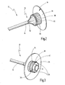
- Figur 2
- eine vergrößerte perspektivische Ansicht des distalen Bereichs eines Handhabungselements, das mit dem medizinischen Instrument verbunden ist;
- Figur 3
- eine perspektivische Ansicht des proximalen Bereichs des Hand-habungselements;
- Figur 4
- eine Situation, in der das Handhabungselement mit der Übergabestation und das medizinische Instrument mit dem sterilisationsempfindlichen Bedienteil verbunden ist; und
- Figur 5
- eine der Darstellung in
Figur 4 vergleichbare Darstellung, wobei das sterilisationsempfindliche Bedienteil von der Übergabestation abgezogen ist und mit dem sterilen Schlauch umhüllt ist. - Eine in
Figuren 1 bis 5 dargestellte Vorrichtung zur sterilen Umhüllung eines sterilisationsempfindlichen Bedienteils ist in ihrer Gesamtheit mit der Bezugsziffer 10 versehen. - Die in
Figur 1 dargestellte erfindungsgemäße Vorrichtung 10 weist ein Handhabungselement 12 auf, das einen zusammengerafften sterilen Schlauch 14 aufweist. Mit dem Schlauch 14 ist ein medizinisches Instrument 16 fest verbunden. - Ferner weist die erfindungsgemäße Vorrichtung 10 eine Übergabestation 18 auf, in der ein sterilisationsempfindliches Bedienteil 20, das hier nur fragmentarisch dargestellt ist, aufgenommen ist.
- Das Handhabungselement 12 weist distalseitig eine Handhabe 22 auf, wie es insbesondere aus der vergrößerten Darstellung in
Figur 2 ersichtlich ist. - Proximalseitig weist das Handhabungselement 12 eine Kupplung 24 auf, die aus der Darstellung in
Figur 3 ersichtlich ist. Mittels der Kupplung 24 wird das Handhabungselement 12 mit der Übergabestation 18 verbunden. - Ferner weist das Handhabungselement 12 ein flächiges Basisteil 26 auf, von dem die Handhabe 22 und die Kupplung 24 vorspringen. In diesem Ausführungsbeispiel ist das Basisteil 26 scheibenförmig ausgebildet. Die Größe des Basisteils 26 ist so gewählt, dass eine Hand, die die Handhabe 22 ergriffen hat, beim Ankoppeln an die Übergabestation 18 mit dieser nicht in Berührung tritt. Dadurch wird vermieden, dass allfällige Kontamination von der nicht sterilen Übergabestation 18 an das Handhabungselement 12 gelangen. Dementsprechend kann vermieden werden, dass der Arzt, der im Einsatz das Handhabungselement 12 erfasst dadurch kontaminiert wird.
- Die Handhabe 22 ist als Ringflansch 28 ausgebildet, in dessen Außenseite ein Kerbenmuster 30 eingeschnitten ist, so dass die Handhabe 22 sicher von Fingern einer menschlichen Hand ergriffen werden kann.
- An der Handhabe 22 ist ein proximales Ende des sterilen Schlauchs 14 fixiert. Ein distales Ende des Schlauchs 14, der in
Figuren 2 und 3 in einer zusammengerafften Form dargestellt ist, ist an dem medizinischen Instrument 16 fixiert. In diesem Ausführungsbeispiel ist das distale Ende 32 des Schlauchs 14 an einem proximalen Endbereich 34 des medizinischen Instruments 16 fixiert. Die Fixierung erfolgt bei diesem Ausführungsbeispiel durch Ankleben des Schlauchs 14 an dem medizinischen Instrument 16. Das proximale Ende 34 des medizinischen Instrumentes 16 steckt in einer hier nicht ersichtlichen Öffnung im Basisteil 26. - Die proximal angeordnete Kupplung 24, die aus der Darstellung von
Figur 3 ersichtlich ist, ist in diesem Ausführungsbeispiel als Bajonettkupplung ausgebildet. - Die als Bajonettkupplung ausgebildete Kupplung 24 weist ein Kupplungselement 36 auf, das Stifte 38, 39 aufweist. An der Übergabestation 18 ist eine Bajonettführung 40 angeordnet, wie es insbesondere aus der Darstellung in
Figur 1 ersichtlich ist. Beim Verbinden des Handhabungselements 12 mit der Übergabestation 18 greifen die Stifte 38, 39 in die Bajonettführung 40 ein. Durch Drehen des Handhabungselements 12 kommt es zum Verriegeln. - Ferner weist das Handhabungselement 12 eine proximalseitig angeordnete Steuernocke 42 auf. Beim Verbinden des Handhabungselements 12 mit der Übergabestation 18 wird die Steuernocke 42, mit einem Kontaktschalter 44, der an der Übergabestation 18 angeordnet ist, in Verbindung gebracht. Dadurch wird ein An- und Abdockmechanismus 60, der noch später in Zusammenhang mit
Figuren 4 und5 näher beschrieben wird, betätigt. - An dem Basisteil 26 ist ein Orientierungsmerkmal 46 angeordnet, dessen Funktion noch später näher beschrieben wird.
- Das medizinische Instrument 16, das mit dem distalen Ende 32 des Schlauchs 14 fest verbunden ist und in den
Figuren 1 bis 5 nur fragmentarisch dargestellt ist, ist in diesem Ausführungsbeispiel als Endoskop 48 ausgebildet. Das in diesem Ausführungsbeispiel dargestellte Endoskop 48 ist als Einweginstrument ausgebildet. - Das als Einweginstrument ausgebildete Endoskop 48 weist folgende Elemente auf, die aus keiner der Figuren ersichtlich sind, nämlich zumindest einen distalseitig angeordneten Video-Sensor mit einem Objektiv, ein Lichtübertragungselement, welches Licht von proximal nach distal leitet, und ein elektrisches Übertragungssystem, welches die Bildinformation überträgt.
- In diesem Ausführungsbeispiel ist das proximale Ende 34 des Endoskops 48 derart angeordnet, dass es proximal über die Kupplung 24 hinausragt, wie es insbesondere aus der Darstellung von
Figur 3 ersichtlich ist. - Das sterilisationsempfindliche Bedienteil 20 ist in diesem Ausführungsbeispiel als ein Handgriff 50 ausgebildet, der mit einem Kabel 52 verbunden ist. Das sterilisationsempfindliche Bedienteil 20 enthält empfindliche elektronische Bauteile und eine integrierte Beleuchtungseinheit mit LEDs bzw. Lichtfasern, die hier nicht dargestellt sind.
- Das Bedienteil 20 ist in der Übergabestation 18 derart aufgenommen, dass dessen distales Ende vor der Übergabestation 18 vorsteht, wie es insbesondere aus der Darstellung von
Figur 1 ersichtlich ist. - Das distale Ende des Bedienteils 20 ist derart ausgebildet, dass es geeignet ist, das proximale 34 Ende des medizinischen Instruments 16 aufzunehmen, so dass das medizinische Instrument 16 mit dem Bedienteil 20 gekoppelt wird.
- Anhand von
Figuren 4 und5 in Verbindung mitFigur 1 soll eine Handhabung der erfindungsgemäßen Vorrichtung 10 erläutert werden. - Das sterilisationsempfindliche Bedienteil 20 wird im nichtsterilen Bereich in der Übergabestation 18 eingeschoben und gegen Herausziehen, Hineinschieben und Verdrehen verriegelt. Solch eine Situation ist in
Figur 1 dargestellt. - Ein Zusammenbau bestehend aus dem Handhabungselement 12, dem sterilen Schlauch 14 und dem mit dem sterilen Schlauch 14 fest verbundenen medizinischen Instrument 16 wird vom Operateur im sterilen Bereich aus einer sterilen Verpackung entnommen.
- Diese kompakte Baueinheit wird von einer sterilen Hand einer Person an der Handhabe 22 ergriffen und der Zusammenbau wird an die Übergabestation 18 gebracht (siehe Pfeil 54,
Figur 1 ). - Zuerst wird das proximale Ende 34 des medizinischen Instruments 16 in das distale Ende des Bedienteils 20, das vor der Übergabestation 18 vorsteht, eingeführt. Dadurch wird das medizinische Instrument 16 mit dem Bedienteil 20 verbunden.
- Gleichzeitig werden die Stifte 38, 39 der Kupplung 24 in die Bajonettführung 40, die an der Übergabestation 18 angeordnet ist, eingeführt. Solch eine Situation ist in
Figur 4 dargestellt. - Beim Anbringen des Handhabungselements 12 an die Übergabestation 18 ist das Handhabungselement 12 derart auszurichten, dass sich das Orientierungsmerkmal 46 des Basisteils 26 in Ausrichtung mit einer Ausgangsstellung 62 des An- und Abdockmechanismus 60 befindet.
- Diese Vorgänge können mit einer einzigen, der sterilen, Hand einer Person durchgeführt werden.
- Durch Drehen der Handhabe 22 von der Ausgangsstellung 62 auf die erste Stellung 64 des An- und Abdockmechanismus 60 wird das Handhabungselement 12 mittels der Bajonettkupplung an der Übergabestation 18 verriegelt (siehe Pfeil 56,
Figur 1 ). - In der ersten Stellung 64 wird gleichzeitig das in der Übergabestation 18 verriegelte Bedienteil 20 zum Herausziehen freigegeben.
- In dieser Stellung 64 wird das medizinische Instrument 16, das im sterilen Bereich angeordnet ist, vom Operateur ergriffen und von der Übergabestation abgezogen (siehe Pfeil 58,
Figur 5 ). Dadurch wird das Bedienteil 20 aus der Übergabestation 18 herausgezogen. Beim Herausziehen entfaltet sich der sterile Schlauch 14 automatisch über das Bedienteil 20 und das Kabel 48. Solch eine Situation ist inFigur 5 dargestellt. - In der ersten Stellung 64 des An- und Abdockmechanismus 60, die als Arbeitsstellung bezeichnet wird, ist das medizinische Instrument 16 mit dem Bedienteil 20 nun frei bewegbar.
- Wurde das Bedienteil 20 zu weit herausgezogen, kann das Bedienteil 20 über kurzzeitiges Betätigen der Handhabe 22 von der ersten Stellung 64 auf eine zweite Stellung 66 zur Rückführung freigegeben werden.
- Nach erfolgtem chirurgischem Eingriff wird das Handhabungselement 12 durch Drehen der Handhabe 22 auf die zweite Stellung 66 des An- und Abdockmechanismus 60 gebracht. In der zweiten Stellung 66 des An- und Abdockmechanismus 60 wird das Bedienteil 20 und damit das Handgriff 48 und das medizinische Instrument 16 zurückgezogen, und zwar so weit bis das Bedienteil 20 in der Übergabestation 18 verriegelt wird. Das Zurückziehen erfolgt über einen Federmechanismus oder elektromotorisch.
- Beim Zurückziehen faltet sich der Schlauch 14 mehr oder weniger vor der Handhabe 22 zusammen.
- Dann wird das Handhabungselement 12 durch Drehen der Handhabe 22 auf eine dritte Stellung 68 des An- und Abdockmechanismus 60 gebracht. In dieser Stellung 68 wird die Verbindung zwischen dem medizinischen Instrument 16 und dem Bedienteil 20 gelöst, so dass das medizinische Instrument 16 von dem Bedienteil 20 getrennt wird.
- Dann wird das Handhabungselement 12 durch Drehen der Handhabe 22 auf eine vierte Stellung 70 des An- und Abdockmechanismus 60 gebracht. In der vierten Stellung 70 wird das Handhabungselement 12 von der Übergabestation 18 gelöst.
- Der von der Übergabestation 18 abgenommene Zusammenbau bestehend aus dem Handhabungselement 12, dem Schlauch 14 und dem medizinischen Instrument 16, das bei diesem Ausführungsbeispiel als Einweginstrument ausgebildet ist, wird ohne Reinigung entsorgt.
- Auch dieser Vorgang kann mit einer Hand durchgeführt werden.
- Wenn ein Mehrweginstrument verwendet wird, ist die Handhabung der erfindungsgemäßen Vorrichtung 10 gleich wie beim Einweginstrument, nur mit dem Unterschied, dass das Mehrweginstrument, bevor es mit dem Schlauch 14 fest verbunden wird, sterilisiert werden muss. Nach erfolgter Arbeit wird das Mehrweginstrument von dem Schlauch 14 getrennt und gereinigt.
Claims (19)
- Vorrichtung zur sterilen Umhüllung eines sterilisationsempfindlichen Bedienteils, das für einen chirurgischen Eingriff mit einem medizinischen Instrument verbindbar ist, mit einem Handhabungselement (12), das an einem distalen Ende einen zusammengerafften sterilen Schlauch (14) aufweist, wobei das Handhabungselement (12) ferner eine Öffnung aufweist, durch die von proximal nach distal das sterilisationsempfindliche Bedienteil (20) in den sterilen Schlauch (14) derart einführbar ist, dass dabei das sterilisationsempfindliche Bedienteil (20) mit dem sterilen Schlauch (14) umhüllbar ist, dadurch gekennzeichnet, dass ein medizinisches Instrument (16) an seinem proximalen Endbereich (34) mit einem distalen Ende (32) des sterilen Schlauchs (14) fest verbunden ist, und dass eine Übergabestation (18), in der das sterilisationsempfindliche Bedienteil (20) aufgenommen ist, vorhanden ist, wobei das Handhabungselement (12) mit der Übergabestation (18) derart verbindbar ist, dass das medizinische Instrument (16) und das sterilisationsempfindliche Bedienteil (20) miteinander verbindbar sind und dass dieser Zusammenbau von der Übergabestation (18) abziehbar ist, wobei der geraffte sterile Schlauch (14) über das sterilisationsempfindliche Bedienteil (20) ziehbar ist.
- Vorrichtung nach Anspruch 1, dadurch gekennzeichnet, dass das Handhabungselement (12) distalsetig eine Handhabe (22) aufweist.
- Vorrichtung nach Anspruch 1 oder 2, dadurch gekennzeichnet, dass das Handhabungselement (12) proximalseitig eine Kupplung (24) aufweist.
- Vorrichtung nach einem der Ansprüche 1 bis 3, dadurch gekennzeichnet, dass das Handhabungselement (12) ein flächiges Basisteil (26) aufweist, von dem die Handhabe (22) und die Kupplung (24) vorspringen.
- Vorrichtung nach einem der Ansprüche 2 bis 4, dadurch gekennzeichnet, dass der sterile Schlauch (14) an der Handhabe (22) befestigt ist.
- Vorrichtung nach einem der Ansprüche 2 bis 5, dadurch gekennzeichnet, dass die Handhabe (22) als Ringflansch (28) ausgebildet ist.
- Vorrichtung nach einem der Ansprüche 3 bis 6, dadurch gekennzeichnet, dass die Kupplung (24) ein Kupplungselement (36) aufweist.
- Vorrichtung nach einem der Ansprüche 3 bis 7, dadurch gekennzeichnet, dass die Kupplung (24) als Bajonettkupplung ausgebildet ist.
- Vorrichtung nach einem der Ansprüche 4 bis 8, dadurch gekennzeichnet, dass das Basisteil (26) ein Orientierungsmerkmal (46) aufweist.
- Vorrichtung nach einem der Ansprüche 1 bis 9, dadurch gekennzeichnet, dass das Handhabungselement (12) und der Schlauch (14) als Einwegelemente ausgebildet sind.
- Vorrichtung nach einem der Ansprüche 1 bis 10, dadurch gekennzeichnet, dass das medizinische Instrument (16) als Einweginstrument ausgebildet ist.
- Vorrichtung nach einem der Ansprüche 1 bis 10, dadurch gekennzeichnet, dass das medizinische Instrument (16) als Mehrweginstrument ausgebildet ist.
- Vorrichtung nach einem der Ansprüche 1 bis 12, dadurch gekennzeichnet, dass die Übergabestation (18) einen An- und Abdockmechanismus (60) aufweist, der über die Handhabe (22) betätigbar ist.
- Vorrichtung nach Anspruch 13, dadurch gekennzeichnet, dass der An- und Abdockmechanismus (60) über Bedienelemente, die an der Übergabestation (18) angeordnet sind, betätigbar ist.
- Vorrichtung nach Anspruch 13 oder 14, dadurch gekennzeichnet, dass der An- und Abdockmechanismus (60) eine Ausgangstellung (62) aufweist, in der das sterilisationsempfindliche Bedienteil (20) in der Übergabestation (18) verriegelt ist.
- Vorrichtung nach einem der Ansprüche 13 bis 15, dadurch gekennzeichnet, dass der An- und Abdockmechanismus (60) eine erste Stellung (64) aufweist, in der das Handhabungselement (12) an der Übergabestation (18) verriegelt ist und das sterilisationsempfindliche Bedienteil (20) und das damit verbundene medizinische Instrument (16) zum Abziehen von der Übergabestation (18) freigegeben sind.
- Vorrichtung nach einem der Ansprüche 13 bis 16, dadurch gekennzeichnet, dass der An- und Abdockmechanismus (60) eine zweite Stellung (66) aufweist, in der das sterilisationsempfindliche Bedienteil (20) und das damit verbundene medizinische Instrument (16) zum Rückführen zur Übergabestation (18) freigegeben sind.
- Vorrichtung nach einem der Ansprüche 13 bis 17, dadurch gekennzeichnet, dass der An- und Abdockmechanismus (60) eine dritte Stellung (68) aufweist, in der die Verbindung zwischen dem medizinischen Instrument (16) und dem sterilisationsempfindlichen Bedienteil (20) lösbar ist.
- Vorrichtung nach einem der Ansprüche 13 bis 18, dadurch gekennzeichnet, dass der An- und Abdockmechanismus (60) eine vierte Stellung (70) aufweist, in der die Verriegelung des Handhabungselements (12) mit der Übergabestation (18) lösbar ist.
Applications Claiming Priority (1)
| Application Number | Priority Date | Filing Date | Title |
|---|---|---|---|
| DE102007026235A DE102007026235A1 (de) | 2007-05-31 | 2007-05-31 | Vorrichtung zur sterilen Umhüllung eines sterilisationsempfindlichen Bedienteils |
Publications (3)
| Publication Number | Publication Date |
|---|---|
| EP1997452A2 true EP1997452A2 (de) | 2008-12-03 |
| EP1997452A3 EP1997452A3 (de) | 2010-03-31 |
| EP1997452B1 EP1997452B1 (de) | 2014-09-24 |
Family
ID=39745050
Family Applications (1)
| Application Number | Title | Priority Date | Filing Date |
|---|---|---|---|
| EP08009824.7A Not-in-force EP1997452B1 (de) | 2007-05-31 | 2008-05-29 | Vorrichtung zur sterilen Umhüllung eines sterilisationsempfindlichen Bedienteils |
Country Status (3)
| Country | Link |
|---|---|
| US (1) | US8613699B2 (de) |
| EP (1) | EP1997452B1 (de) |
| DE (1) | DE102007026235A1 (de) |
Cited By (1)
| Publication number | Priority date | Publication date | Assignee | Title |
|---|---|---|---|---|
| GB2530853A (en) * | 2014-07-21 | 2016-04-06 | Creo Medical Ltd | Electrical connector for an electrosurgical apparatus |
Families Citing this family (6)
| Publication number | Priority date | Publication date | Assignee | Title |
|---|---|---|---|---|
| US8816856B2 (en) * | 2009-10-13 | 2014-08-26 | Augusta E.N.T., P.C. | Medical instrument cleaning system and method |
| US20150068939A1 (en) * | 2010-09-24 | 2015-03-12 | John Russell Seitz, III | Multifunctional enclosure system for medical probes and method of use |
| DE102011079598B4 (de) | 2011-07-21 | 2019-10-17 | Karl Storz Se & Co. Kg | Leitungsreservoir zum Aufnehmen einer elektrischen, optischen oder Fluid-Leitung |
| DE102016109601A1 (de) * | 2016-05-25 | 2017-11-30 | avateramedical GmBH | Anordnung zur sterilen Handhabung von nicht sterilen Einheiten in einer sterilen Umgebung |
| US10912622B2 (en) * | 2019-06-01 | 2021-02-09 | Nizam M. Meah | Disposable endoscope shield |
| US20230022031A1 (en) * | 2020-01-07 | 2023-01-26 | Gyrus Acmi, Inc. D/B/A Olympus Surgical Technologies America | Power port connector for medical device |
Citations (1)
| Publication number | Priority date | Publication date | Assignee | Title |
|---|---|---|---|---|
| DE3920508A1 (de) | 1989-06-22 | 1991-01-10 | Norbert Lemke | Vorrichtung zur sterilen umhuellung von instrumenten |
Family Cites Families (12)
| Publication number | Priority date | Publication date | Assignee | Title |
|---|---|---|---|---|
| DE8815549U1 (de) * | 1988-09-23 | 1989-02-23 | Herzberg, Wolfgang, Dr. med., 2000 Wedel | Einmal-Überzug aus einer Schlauchfolie für Arthroskopiekameras |
| DE8812027U1 (de) * | 1988-09-23 | 1988-11-24 | Herzberg, Wolfgang, Dr. med., 2000 Wedel | Einrichtung mit einem Einweg-Überzug für Arthroskopiekameras |
| US4911148A (en) * | 1989-03-14 | 1990-03-27 | Intramed Laboratories, Inc. | Deflectable-end endoscope with detachable flexible shaft assembly |
| WO1992004932A1 (en) * | 1990-09-21 | 1992-04-02 | Baxter International Inc. | Adjustable catheter contamination shield |
| US5188093A (en) * | 1991-02-04 | 1993-02-23 | Citation Medical Corporation | Portable arthroscope with periscope optics |
| US5269761A (en) * | 1992-08-17 | 1993-12-14 | Mark Stehrenberger | Safety hypodermic needle guard |
| US5562602A (en) * | 1993-03-15 | 1996-10-08 | Olympus Optical Co., Ltd. | Insert cover portion of endoscope cover, insert cover portion having channels of endoscope cover, endoscope-cover-type endoscope, endoscope-cover-system endoscope and endoscope apparatus |
| US5827319A (en) * | 1996-05-20 | 1998-10-27 | Innerdyne, Inc. | Radially expandable access system having disposable and reusable components |
| JP2002534200A (ja) * | 1999-01-19 | 2002-10-15 | タイコ ヘルスケア グループ リミテッド パートナーシップ | 外科手術器具のための鞘部材およびアプリケータ |
| US6908428B2 (en) * | 2003-09-04 | 2005-06-21 | Sightline Technologies Ltd. | Sleeve for endoscopic tools |
| EP1948029A2 (de) * | 2005-11-17 | 2008-07-30 | Stryker GI Ltd | Schutzabdeckung für ein endoskopisches werkzeug |
| DE202007014102U1 (de) * | 2007-10-09 | 2008-02-28 | Pacific Hospital Supply Co., Ltd. | Hüllenaufbau für ein tragbares medizinisches Gerät |
-
2007
- 2007-05-31 DE DE102007026235A patent/DE102007026235A1/de not_active Ceased
-
2008
- 2008-05-29 EP EP08009824.7A patent/EP1997452B1/de not_active Not-in-force
- 2008-05-30 US US12/130,760 patent/US8613699B2/en not_active Expired - Fee Related
Patent Citations (1)
| Publication number | Priority date | Publication date | Assignee | Title |
|---|---|---|---|---|
| DE3920508A1 (de) | 1989-06-22 | 1991-01-10 | Norbert Lemke | Vorrichtung zur sterilen umhuellung von instrumenten |
Cited By (3)
| Publication number | Priority date | Publication date | Assignee | Title |
|---|---|---|---|---|
| GB2530853A (en) * | 2014-07-21 | 2016-04-06 | Creo Medical Ltd | Electrical connector for an electrosurgical apparatus |
| GB2530853B (en) * | 2014-07-21 | 2018-01-03 | Creo Medical Ltd | Electrical connector for an electrosurgical apparatus |
| US10610284B2 (en) | 2014-07-21 | 2020-04-07 | Crea Medical Limited | Electrical connector for an electrosurgical apparatus |
Also Published As
| Publication number | Publication date |
|---|---|
| US8613699B2 (en) | 2013-12-24 |
| EP1997452B1 (de) | 2014-09-24 |
| US20080300553A1 (en) | 2008-12-04 |
| EP1997452A3 (de) | 2010-03-31 |
| DE102007026235A1 (de) | 2008-12-04 |
Similar Documents
| Publication | Publication Date | Title |
|---|---|---|
| DE19715507C1 (de) | Medizinisches Instrument mit einem tubusartigen Element und einem dazu abgewinkelten Griff, insbesondere Mediastinoskop, Laryngoskop, Divertikuloskop | |
| EP1997452B1 (de) | Vorrichtung zur sterilen Umhüllung eines sterilisationsempfindlichen Bedienteils | |
| EP1997421B1 (de) | Videoendoskop | |
| EP3723576B1 (de) | Vorrichtung und verfahren zur kontaminationsfreien durchführung einer endoskopischen untersuchung | |
| EP2200497B1 (de) | Modulares endoskop | |
| DE69610488T2 (de) | Sterilisierbares endoskop mit einer trennbaren wegwerfbaren anordnung | |
| DE69931621T2 (de) | Endoskopisches instrument mit arbeitskanal | |
| DE102009000685B4 (de) | Laserhandstück | |
| EP1681014A1 (de) | Antrieb für ein Endoskop | |
| DE102015015041A1 (de) | Endoskop mit einem wiederverwendbaren Teil und einem Einwegteil | |
| EP1601293A1 (de) | Medizinisches instrumentarium zum schaffen eines operativen arbeitsraumes bei kieferoperationen | |
| DE102015113430A1 (de) | Endoskopverpackung mit zwei separaten Kammern | |
| EP3203896B1 (de) | Endoskop mit lösbarem handgriff | |
| EP4046583B1 (de) | Elektrochirurgisches handgerät und kontaktkörper für elektrochirurgisches handgerät | |
| DE202014000037U1 (de) | Endoskopievorrichtung | |
| EP2848189B1 (de) | Endoskopisches System | |
| EP3203897B1 (de) | Handgriff eines endoskops | |
| EP3151723B1 (de) | Endoskop mit mehreren proximalen arbeitskanal-anschlüssen | |
| DE4216874C1 (de) | ||
| DE10241946A1 (de) | Vorrichtung zur minimal-invasiven chirurgischen Fremdkörperentfernung | |
| DE102022103916A1 (de) | Halterung zum Halten eines Endoskops und System umfassend eine solche Halterung | |
| DE4445105A1 (de) | Operationsinstrument | |
| DE4330776A1 (de) | Operationsinstrument | |
| DE4440546A1 (de) | Operationsinstrument |
Legal Events
| Date | Code | Title | Description |
|---|---|---|---|
| PUAI | Public reference made under article 153(3) epc to a published international application that has entered the european phase |
Free format text: ORIGINAL CODE: 0009012 |
|
| AK | Designated contracting states |
Kind code of ref document: A2 Designated state(s): AT BE BG CH CY CZ DE DK EE ES FI FR GB GR HR HU IE IS IT LI LT LU LV MC MT NL NO PL PT RO SE SI SK TR |
|
| AX | Request for extension of the european patent |
Extension state: AL BA MK RS |
|
| PUAL | Search report despatched |
Free format text: ORIGINAL CODE: 0009013 |
|
| AK | Designated contracting states |
Kind code of ref document: A3 Designated state(s): AT BE BG CH CY CZ DE DK EE ES FI FR GB GR HR HU IE IS IT LI LT LU LV MC MT NL NO PL PT RO SE SI SK TR |
|
| AX | Request for extension of the european patent |
Extension state: AL BA MK RS |
|
| 17P | Request for examination filed |
Effective date: 20100930 |
|
| AKX | Designation fees paid |
Designated state(s): AT BE BG CH CY CZ DE DK EE ES FI FR GB GR HR HU IE IS IT LI LT LU LV MC MT NL NO PL PT RO SE SI SK TR |
|
| GRAP | Despatch of communication of intention to grant a patent |
Free format text: ORIGINAL CODE: EPIDOSNIGR1 |
|
| INTG | Intention to grant announced |
Effective date: 20140424 |
|
| GRAS | Grant fee paid |
Free format text: ORIGINAL CODE: EPIDOSNIGR3 |
|
| GRAA | (expected) grant |
Free format text: ORIGINAL CODE: 0009210 |
|
| AK | Designated contracting states |
Kind code of ref document: B1 Designated state(s): AT BE BG CH CY CZ DE DK EE ES FI FR GB GR HR HU IE IS IT LI LT LU LV MC MT NL NO PL PT RO SE SI SK TR |
|
| REG | Reference to a national code |
Ref country code: GB Ref legal event code: FG4D Free format text: NOT ENGLISH |
|
| REG | Reference to a national code |
Ref country code: CH Ref legal event code: EP |
|
| REG | Reference to a national code |
Ref country code: AT Ref legal event code: REF Ref document number: 688242 Country of ref document: AT Kind code of ref document: T Effective date: 20141015 |
|
| REG | Reference to a national code |
Ref country code: IE Ref legal event code: FG4D Free format text: LANGUAGE OF EP DOCUMENT: GERMAN |
|
| REG | Reference to a national code |
Ref country code: DE Ref legal event code: R096 Ref document number: 502008012236 Country of ref document: DE Effective date: 20141106 |
|
| PG25 | Lapsed in a contracting state [announced via postgrant information from national office to epo] |
Ref country code: NO Free format text: LAPSE BECAUSE OF FAILURE TO SUBMIT A TRANSLATION OF THE DESCRIPTION OR TO PAY THE FEE WITHIN THE PRESCRIBED TIME-LIMIT Effective date: 20141224 Ref country code: FI Free format text: LAPSE BECAUSE OF FAILURE TO SUBMIT A TRANSLATION OF THE DESCRIPTION OR TO PAY THE FEE WITHIN THE PRESCRIBED TIME-LIMIT Effective date: 20140924 Ref country code: GR Free format text: LAPSE BECAUSE OF FAILURE TO SUBMIT A TRANSLATION OF THE DESCRIPTION OR TO PAY THE FEE WITHIN THE PRESCRIBED TIME-LIMIT Effective date: 20141225 Ref country code: SE Free format text: LAPSE BECAUSE OF FAILURE TO SUBMIT A TRANSLATION OF THE DESCRIPTION OR TO PAY THE FEE WITHIN THE PRESCRIBED TIME-LIMIT Effective date: 20140924 Ref country code: LT Free format text: LAPSE BECAUSE OF FAILURE TO SUBMIT A TRANSLATION OF THE DESCRIPTION OR TO PAY THE FEE WITHIN THE PRESCRIBED TIME-LIMIT Effective date: 20140924 |
|
| REG | Reference to a national code |
Ref country code: LT Ref legal event code: MG4D Ref country code: NL Ref legal event code: VDEP Effective date: 20140924 |
|
| PG25 | Lapsed in a contracting state [announced via postgrant information from national office to epo] |
Ref country code: CY Free format text: LAPSE BECAUSE OF FAILURE TO SUBMIT A TRANSLATION OF THE DESCRIPTION OR TO PAY THE FEE WITHIN THE PRESCRIBED TIME-LIMIT Effective date: 20140924 Ref country code: HR Free format text: LAPSE BECAUSE OF FAILURE TO SUBMIT A TRANSLATION OF THE DESCRIPTION OR TO PAY THE FEE WITHIN THE PRESCRIBED TIME-LIMIT Effective date: 20140924 Ref country code: LV Free format text: LAPSE BECAUSE OF FAILURE TO SUBMIT A TRANSLATION OF THE DESCRIPTION OR TO PAY THE FEE WITHIN THE PRESCRIBED TIME-LIMIT Effective date: 20140924 |
|
| PG25 | Lapsed in a contracting state [announced via postgrant information from national office to epo] |
Ref country code: NL Free format text: LAPSE BECAUSE OF FAILURE TO SUBMIT A TRANSLATION OF THE DESCRIPTION OR TO PAY THE FEE WITHIN THE PRESCRIBED TIME-LIMIT Effective date: 20140924 |
|
| PG25 | Lapsed in a contracting state [announced via postgrant information from national office to epo] |
Ref country code: IS Free format text: LAPSE BECAUSE OF FAILURE TO SUBMIT A TRANSLATION OF THE DESCRIPTION OR TO PAY THE FEE WITHIN THE PRESCRIBED TIME-LIMIT Effective date: 20150124 Ref country code: SK Free format text: LAPSE BECAUSE OF FAILURE TO SUBMIT A TRANSLATION OF THE DESCRIPTION OR TO PAY THE FEE WITHIN THE PRESCRIBED TIME-LIMIT Effective date: 20140924 Ref country code: EE Free format text: LAPSE BECAUSE OF FAILURE TO SUBMIT A TRANSLATION OF THE DESCRIPTION OR TO PAY THE FEE WITHIN THE PRESCRIBED TIME-LIMIT Effective date: 20140924 Ref country code: CZ Free format text: LAPSE BECAUSE OF FAILURE TO SUBMIT A TRANSLATION OF THE DESCRIPTION OR TO PAY THE FEE WITHIN THE PRESCRIBED TIME-LIMIT Effective date: 20140924 Ref country code: ES Free format text: LAPSE BECAUSE OF FAILURE TO SUBMIT A TRANSLATION OF THE DESCRIPTION OR TO PAY THE FEE WITHIN THE PRESCRIBED TIME-LIMIT Effective date: 20140924 Ref country code: RO Free format text: LAPSE BECAUSE OF FAILURE TO SUBMIT A TRANSLATION OF THE DESCRIPTION OR TO PAY THE FEE WITHIN THE PRESCRIBED TIME-LIMIT Effective date: 20140924 Ref country code: PT Free format text: LAPSE BECAUSE OF FAILURE TO SUBMIT A TRANSLATION OF THE DESCRIPTION OR TO PAY THE FEE WITHIN THE PRESCRIBED TIME-LIMIT Effective date: 20150126 |
|
| PG25 | Lapsed in a contracting state [announced via postgrant information from national office to epo] |
Ref country code: PL Free format text: LAPSE BECAUSE OF FAILURE TO SUBMIT A TRANSLATION OF THE DESCRIPTION OR TO PAY THE FEE WITHIN THE PRESCRIBED TIME-LIMIT Effective date: 20140924 |
|
| REG | Reference to a national code |
Ref country code: DE Ref legal event code: R097 Ref document number: 502008012236 Country of ref document: DE |
|
| PG25 | Lapsed in a contracting state [announced via postgrant information from national office to epo] |
Ref country code: DK Free format text: LAPSE BECAUSE OF FAILURE TO SUBMIT A TRANSLATION OF THE DESCRIPTION OR TO PAY THE FEE WITHIN THE PRESCRIBED TIME-LIMIT Effective date: 20140924 |
|
| PLBE | No opposition filed within time limit |
Free format text: ORIGINAL CODE: 0009261 |
|
| STAA | Information on the status of an ep patent application or granted ep patent |
Free format text: STATUS: NO OPPOSITION FILED WITHIN TIME LIMIT |
|
| 26N | No opposition filed |
Effective date: 20150625 |
|
| REG | Reference to a national code |
Ref country code: CH Ref legal event code: PL |
|
| PG25 | Lapsed in a contracting state [announced via postgrant information from national office to epo] |
Ref country code: CH Free format text: LAPSE BECAUSE OF NON-PAYMENT OF DUE FEES Effective date: 20150531 Ref country code: LU Free format text: LAPSE BECAUSE OF FAILURE TO SUBMIT A TRANSLATION OF THE DESCRIPTION OR TO PAY THE FEE WITHIN THE PRESCRIBED TIME-LIMIT Effective date: 20150529 Ref country code: MC Free format text: LAPSE BECAUSE OF FAILURE TO SUBMIT A TRANSLATION OF THE DESCRIPTION OR TO PAY THE FEE WITHIN THE PRESCRIBED TIME-LIMIT Effective date: 20140924 Ref country code: LI Free format text: LAPSE BECAUSE OF NON-PAYMENT OF DUE FEES Effective date: 20150531 |
|
| REG | Reference to a national code |
Ref country code: IE Ref legal event code: MM4A |
|
| PG25 | Lapsed in a contracting state [announced via postgrant information from national office to epo] |
Ref country code: SI Free format text: LAPSE BECAUSE OF FAILURE TO SUBMIT A TRANSLATION OF THE DESCRIPTION OR TO PAY THE FEE WITHIN THE PRESCRIBED TIME-LIMIT Effective date: 20140924 |
|
| REG | Reference to a national code |
Ref country code: FR Ref legal event code: PLFP Year of fee payment: 9 |
|
| PG25 | Lapsed in a contracting state [announced via postgrant information from national office to epo] |
Ref country code: IE Free format text: LAPSE BECAUSE OF NON-PAYMENT OF DUE FEES Effective date: 20150529 |
|
| REG | Reference to a national code |
Ref country code: AT Ref legal event code: MM01 Ref document number: 688242 Country of ref document: AT Kind code of ref document: T Effective date: 20150529 |
|
| PG25 | Lapsed in a contracting state [announced via postgrant information from national office to epo] |
Ref country code: AT Free format text: LAPSE BECAUSE OF NON-PAYMENT OF DUE FEES Effective date: 20150529 |
|
| PG25 | Lapsed in a contracting state [announced via postgrant information from national office to epo] |
Ref country code: MT Free format text: LAPSE BECAUSE OF FAILURE TO SUBMIT A TRANSLATION OF THE DESCRIPTION OR TO PAY THE FEE WITHIN THE PRESCRIBED TIME-LIMIT Effective date: 20140924 |
|
| REG | Reference to a national code |
Ref country code: FR Ref legal event code: PLFP Year of fee payment: 10 |
|
| PG25 | Lapsed in a contracting state [announced via postgrant information from national office to epo] |
Ref country code: BG Free format text: LAPSE BECAUSE OF FAILURE TO SUBMIT A TRANSLATION OF THE DESCRIPTION OR TO PAY THE FEE WITHIN THE PRESCRIBED TIME-LIMIT Effective date: 20140924 Ref country code: HU Free format text: LAPSE BECAUSE OF FAILURE TO SUBMIT A TRANSLATION OF THE DESCRIPTION OR TO PAY THE FEE WITHIN THE PRESCRIBED TIME-LIMIT; INVALID AB INITIO Effective date: 20080529 |
|
| PG25 | Lapsed in a contracting state [announced via postgrant information from national office to epo] |
Ref country code: BE Free format text: LAPSE BECAUSE OF NON-PAYMENT OF DUE FEES Effective date: 20150531 |
|
| PG25 | Lapsed in a contracting state [announced via postgrant information from national office to epo] |
Ref country code: TR Free format text: LAPSE BECAUSE OF FAILURE TO SUBMIT A TRANSLATION OF THE DESCRIPTION OR TO PAY THE FEE WITHIN THE PRESCRIBED TIME-LIMIT Effective date: 20140924 |
|
| REG | Reference to a national code |
Ref country code: DE Ref legal event code: R081 Ref document number: 502008012236 Country of ref document: DE Owner name: KARL STORZ SE & CO. KG INTELLECTUAL PROPERTY, DE Free format text: FORMER OWNER: KARL STORZ GMBH & CO. KG, 78532 TUTTLINGEN, DE Ref country code: DE Ref legal event code: R082 Ref document number: 502008012236 Country of ref document: DE Representative=s name: WITTE, WELLER & PARTNER PATENTANWAELTE MBB, DE Ref country code: DE Ref legal event code: R081 Ref document number: 502008012236 Country of ref document: DE Owner name: KARL STORZ SE & CO. KG, DE Free format text: FORMER OWNER: KARL STORZ GMBH & CO. KG, 78532 TUTTLINGEN, DE |
|
| REG | Reference to a national code |
Ref country code: FR Ref legal event code: PLFP Year of fee payment: 11 |
|
| PGFP | Annual fee paid to national office [announced via postgrant information from national office to epo] |
Ref country code: IT Payment date: 20180420 Year of fee payment: 11 |
|
| PG25 | Lapsed in a contracting state [announced via postgrant information from national office to epo] |
Ref country code: IT Free format text: LAPSE BECAUSE OF NON-PAYMENT OF DUE FEES Effective date: 20190529 |
|
| PGFP | Annual fee paid to national office [announced via postgrant information from national office to epo] |
Ref country code: FR Payment date: 20210421 Year of fee payment: 14 |
|
| PGFP | Annual fee paid to national office [announced via postgrant information from national office to epo] |
Ref country code: GB Payment date: 20210422 Year of fee payment: 14 |
|
| GBPC | Gb: european patent ceased through non-payment of renewal fee |
Effective date: 20220529 |
|
| PG25 | Lapsed in a contracting state [announced via postgrant information from national office to epo] |
Ref country code: FR Free format text: LAPSE BECAUSE OF NON-PAYMENT OF DUE FEES Effective date: 20220531 |
|
| PG25 | Lapsed in a contracting state [announced via postgrant information from national office to epo] |
Ref country code: GB Free format text: LAPSE BECAUSE OF NON-PAYMENT OF DUE FEES Effective date: 20220529 |
|
| P01 | Opt-out of the competence of the unified patent court (upc) registered |
Effective date: 20230527 |
|
| PGFP | Annual fee paid to national office [announced via postgrant information from national office to epo] |
Ref country code: DE Payment date: 20230419 Year of fee payment: 16 |
|
| REG | Reference to a national code |
Ref country code: DE Ref legal event code: R119 Ref document number: 502008012236 Country of ref document: DE |
|
| PG25 | Lapsed in a contracting state [announced via postgrant information from national office to epo] |
Ref country code: DE Free format text: LAPSE BECAUSE OF NON-PAYMENT OF DUE FEES Effective date: 20241203 |