EP1996820B1 - Hydraulische ventilanordnung - Google Patents
Hydraulische ventilanordnung Download PDFInfo
- Publication number
- EP1996820B1 EP1996820B1 EP07703334A EP07703334A EP1996820B1 EP 1996820 B1 EP1996820 B1 EP 1996820B1 EP 07703334 A EP07703334 A EP 07703334A EP 07703334 A EP07703334 A EP 07703334A EP 1996820 B1 EP1996820 B1 EP 1996820B1
- Authority
- EP
- European Patent Office
- Prior art keywords
- valve
- pressure
- consumer
- spool
- conduit
- Prior art date
- Legal status (The legal status is an assumption and is not a legal conclusion. Google has not performed a legal analysis and makes no representation as to the accuracy of the status listed.)
- Not-in-force
Links
Images


Classifications
-
- F—MECHANICAL ENGINEERING; LIGHTING; HEATING; WEAPONS; BLASTING
- F15—FLUID-PRESSURE ACTUATORS; HYDRAULICS OR PNEUMATICS IN GENERAL
- F15B—SYSTEMS ACTING BY MEANS OF FLUIDS IN GENERAL; FLUID-PRESSURE ACTUATORS, e.g. SERVOMOTORS; DETAILS OF FLUID-PRESSURE SYSTEMS, NOT OTHERWISE PROVIDED FOR
- F15B13/00—Details of servomotor systems ; Valves for servomotor systems
- F15B13/02—Fluid distribution or supply devices characterised by their adaptation to the control of servomotors
- F15B13/04—Fluid distribution or supply devices characterised by their adaptation to the control of servomotors for use with a single servomotor
- F15B13/0401—Valve members; Fluid interconnections therefor
- F15B13/0402—Valve members; Fluid interconnections therefor for linearly sliding valves, e.g. spool valves
- F15B13/0403—Valve members; Fluid interconnections therefor for linearly sliding valves, e.g. spool valves a secondary valve member sliding within the main spool, e.g. for regeneration flow
-
- F—MECHANICAL ENGINEERING; LIGHTING; HEATING; WEAPONS; BLASTING
- F15—FLUID-PRESSURE ACTUATORS; HYDRAULICS OR PNEUMATICS IN GENERAL
- F15B—SYSTEMS ACTING BY MEANS OF FLUIDS IN GENERAL; FLUID-PRESSURE ACTUATORS, e.g. SERVOMOTORS; DETAILS OF FLUID-PRESSURE SYSTEMS, NOT OTHERWISE PROVIDED FOR
- F15B21/00—Common features of fluid actuator systems; Fluid-pressure actuator systems or details thereof, not covered by any other group of this subclass
- F15B21/04—Special measures taken in connection with the properties of the fluid
- F15B21/047—Preventing foaming, churning or cavitation
-
- Y—GENERAL TAGGING OF NEW TECHNOLOGICAL DEVELOPMENTS; GENERAL TAGGING OF CROSS-SECTIONAL TECHNOLOGIES SPANNING OVER SEVERAL SECTIONS OF THE IPC; TECHNICAL SUBJECTS COVERED BY FORMER USPC CROSS-REFERENCE ART COLLECTIONS [XRACs] AND DIGESTS
- Y10—TECHNICAL SUBJECTS COVERED BY FORMER USPC
- Y10T—TECHNICAL SUBJECTS COVERED BY FORMER US CLASSIFICATION
- Y10T137/00—Fluid handling
- Y10T137/2496—Self-proportioning or correlating systems
- Y10T137/2559—Self-controlled branched flow systems
- Y10T137/2574—Bypass or relief controlled by main line fluid condition
- Y10T137/2605—Pressure responsive
Definitions
- the invention relates to a hydraulic valve arrangement, which is used in particular for controlling hydraulic consumers on mobile machines and having the features of the preamble of patent claim 1.
- Such a valve arrangement is for example from the US 2002/050295 , of the DE 199 48 232 A1 , of the DE 103 25 294 A1 , of the EP 1 092 095 B1 or from the data sheet RD 64 295 / 07.02 or the data sheet RD 64 282 / 05.00 the applicant and can be configured as a single valve disc, which can be assembled with another valve disc to a control block, or as a valve disc of a so-called monoblock.
- valve discs from the cited Vorverö pretiffisme are designed as so-called load-sensing valves and contain in a valve bore of a valve housing a valve spool, with which the opening cross-section of a metering orifice and the flow direction of the pressurized fluid in the existing consumer channels can be controlled.
- valve housings also a pressure compensator is housed in a further bore, which is arranged at the valve disc according to the data sheet RD 64 282 / 05.00 upstream of the metering orifice and the control piston in the closing direction of the pressure before the metering orifice and in the opening direction of the pressure to the metering orifice and a spring is acted upon.
- the pressure balance is located downstream of the metering orifice and is acted upon in the closing direction of the highest load pressure of all simultaneously actuated hydraulic consumers and in the opening direction of the pressure to the metering orifice.
- Such valve discs allow a load pressure-independent flow distribution, if at the same time several hydraulic consumers to be supplied with pressurized fluid and the pumped by a pump amount of pressurized fluid is less than the requested amount of pressurized fluid.
- valve disks in the valve housing contain two pressure limiting and feed valves, one of which is associated with one of the two consumer channels.
- a pressure limiting and feed valve responds regardless of the position of the valve spool when the pressure in the corresponding consumer channel reaches a certain value and limits the pressure to this value by throttling pressure fluid from the consumer channel throttled flow away to the drain channel (pressure limiting function). This can happen, for example, when the valve spool shuts off the consumer channel in the neutral position and the pressure fluid located in the consumer channel, in a consumer line connected thereto and in the hydraulic consumer itself is heated and the hydraulic consumer is at a stop.
- the pressure relief and feed valve also responds when the load is acting in the desired direction of travel and the pressure in the consumer passage, through which hydraulic fluid is supplied to the hydraulic fluid, falls below the pressure in the discharge passage (feed function).
- the pressure in the drainage channel can be raised above atmospheric pressure by means of a stowage valve.
- the invention has for its object to further develop a hydraulic valve assembly with the features of the preamble of claim 1, that lower production costs and a smaller size are possible.
- valve housing may be a standard element, the rough shape and further design no longer has to depend on whether the valve disc should contain no, one or two pressure relief and feed valves.
- the valve housing no more space must be provided for the pressure limiting and feed valves, so that it can be smaller than in known valve disks.
- the different variants of valve discs are formed only towards the end of the manufacturing process through the use of a corresponding valve spool, which is adapted in any case, taking into account other aspects of the particular application.
- the valve spool can accommodate one or two pressure relief and feed valves.
- valve spool is movable from the neutral position in both directions in working positions and according to which the cavity in the valve spool is connected via a radial bore with the drainage channel, which is so close to one end of the valve spool, that it is closed with a displacement of the valve spool from the neutral position in the sense of a connection of the second consumer channel with an inlet channel to the drainage channel.
- This embodiment is based on the idea that in a working position the valve spool, in which the consumer channel is connected to the drainage channel, the cavity in the valve spool need not be open to the drainage channel. Accordingly, the radial bore can be placed far outward at the end of the valve spool. A large stroke of the valve spool can be maintained.
- the control chamber which forms the flow channel at the valve bore, does not have to be increased axially.
- valve spool which does not require that the large diameter cavity goes far into the valve spool, and has the valve spool according to claim 5 in the region of the consumer channel an annular groove through which the consumer channel with a Inlet channel or the drainage channel is connected, it leads, as indicated in claim 6, advantageously from the annular groove from a radial bore into the cavity. Through this radial bore pressure fluid flows only when the pressure relief and feed valve responds.
- the patent claim 7 is directed to a hydraulic valve assembly with a pressure relief and feed valve, which can be built with a particularly small diameter, so that the cavity surrounding the wall of the valve spool can be so thick that they readily meet all requirements in terms of dimensional stability and resistance to fracture enough.
- the pressure relief and feed valve according to claim 7 can be further developed according to claims 8 to 11 in an advantageous manner.
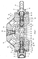
- valve discs after the FIGS. 1 and 2 have a disk-shaped valve housing 10 through which a valve bore 11 located in a central disk plane passes.
- a valve spool 12 is axially movable.
- the valve spool is mechanically actuated and has at a protruding from the valve housing 10 end of a two-fold 13 to which a hand lever can be attached.
- a helical compression spring 17 is tied within the lid with two spring plates 15 and 16, which centers the valve spool in a neutral position and with each movement of the valve spool from the neutral position, regardless of the direction of movement is more compressed by a basic bias.
- valve spool is hydraulically actuated.
- both of the valve housing 10 outstanding ends of the valve spool 12 are covered with solid lids 18 which are bolted to the valve housing 10 and have a connection opening 19 for a control line.
- a control pressure in the one or the other lid can be controlled via the control lines, which generates a force on the cross-sectional area of the valve spool 12, which binds the valve spool so far against the as in the first embodiment between two spring plates 15 and 16 Helical compression spring 17 shifts until there is an equilibrium between the pressure force and the spring force.
- the valve bore 11 is surrounded in both embodiments of eight axially spaced control chambers, which serve to control the inflow of hydraulic oil from a hydraulic pump to a hydraulic consumer, for example to a hydraulic cylinder, and from the hydraulic consumer to a tank.
- control chambers 25 and 26 in the in the FIGS. 1 and 2 shown neutral position of the valve spool 12 are fluidly separated from each other by a slide collar 27 to which connects on both sides a slide neck with an annular groove 28 and 29 and has two rows of Feinsteuemuten 30 and 31, which are offset in the circumferential direction and from where the fine control grooves 30 to the annular groove 28 and the Feinsteuemuten 31 to the annular groove 29 are open.
- the control chamber 25 is provided for connection to a pump line and therefore may also be referred to as a pump chamber.
- the control chamber 26 is an intermediate chamber. Depending on the direction, into which the valve spool 12 moves out of the neutral position, a flow cross section is opened by the fine control grooves 30 or by the fine control grooves 31 from the pump chamber 25 to the intermediate chamber 26, which forms the metering orifice of the valve assembly.
- a consumer chamber 36 follows the inlet chamber 32 and a consumer chamber 37 onto the inlet chamber 33.
- Each consumer chamber is part of a consumer channel 38 or 39 terminating in a consumer connection of the valve housing 10.
- Each consumer chamber 36 and 37 is followed by a drain chamber 40 or 41.
- the two drain chambers are connected to each other in a completed valve block and part of a drain channel 42, which, optionally via a backup valve, leads to a tank connection.
- valve spool 12 In the neutral position of the valve spool 12 all control chambers 25, 26, 32, 33, 36, 37, 40 and 41 are shut off from each other. If the valve spool 12 is moved out of the neutral position, the metering orifice is opened by the fine control grooves 30 or 31. In addition, the one consumer chamber is opened to a feed chamber and the other consumer chamber to a drain chamber.
- the valve disk according to FIG. 1 also has two pressure-limiting and feed valves 45 and 46 and the valve disk FIG. 2 nor a pressure limiting and feed valve 47.
- the pressure-limiting and feed valves are each in a cavity 48, 49 (FIG. FIG. 1 ) or 50 FIG. 2 ) of the valve spool 12 housed.
- the valve spool is equipped with two different pressure relief and feed valves. Of course, it can also have two equal pressure relief and feed valves.
- the cavities 48, 49 and 50 are each introduced from an end face of a main part of the valve spool 12 into the main part and closed by a respective end piece 51, 52 or 53 screwed into the main part.
- the pressure relief and feed valves separate a drain chamber side first region of a cavity from a consumer chamber side, second region of a cavity.
- the first area is open via a radial bore 55 in the valve spool 12 to the outside thereof.
- the radial bore 55 in turn is in the neutral position and in an adjustment of the valve spool in a direction in which the corresponding consumer chamber 36 or 37 is connected to the associated inlet chamber, to the drain chamber 40 thereby open.
- the radial bore 55 is closed after a short path. For the function, this has no effect, since the corresponding consumer chamber via the valve spool is already connected to the drain chamber.
- the second region of the two cavities 48 and 49 FIG. 1 is open via two axially spaced rows of radial bores 56 and 57 to the outside of the valve spool.
- the holes 56 and 57 are open to the outside of the respective consumer chamber 36 and 37 out.
- the radial bores 57 of the cavity 48 remain open to the consumer chamber 36, while the radial bores 56 are closed to consumer chamber 36 and opened to the drain chamber 40 out.
- the radial bores 56 of the cavity 49 remain open to the consumer chamber 37 and the radial bores 57 of the cavity 49 are closed to the consumer chamber 37 and opened to the inlet chamber 33 out.
- Hydraulic oil can now, coming from the metering orifice and the pressure compensator ago coming from the inlet chamber 33, the radial bores 57, the second region and the radial bores 56 of the cavity 49 of the consumer chamber 37 and from there a hydraulic consumer. From this back flowing hydraulic oil passes through the load chamber 36, the radial bores 57, the second region and the radial bores 56 of the cavity 48 in the drain chamber 40.
- Each of the pressure limiting and supply valves 45, 46 and 47 has a valve body 70 which in the opening direction of the pressure in the corresponding consumer chamber and in the closing direction from the pressure in the adjacent drain chamber and a strong helical compression spring 71 whose pressure equivalent may be, for example, 300 bar is acted upon and to limit the pressure in a consumer chamber opens a flow cross-section of the consumer chamber to the adjacent drain chamber.
- each Druckbegrenzungs- and feed valve has a valve body 72 which is acted upon in the closing direction by the pressure in the corresponding consumer chamber and in the opening direction of the pressure in the adjacent drain chamber and a weak helical compression spring 73, the pressure equivalent, for example, 0.5 bar.
- the valve body 72 opens a flow area, so that hydraulic oil from the discharge chamber is fed into the consumer chamber.
- the valve body 70 has a guide rod 74 which, after an all-round recess 75, carries a closing cone 76 which, facing the recess, has a conical seat surface 77.
- the guide rod 74 of the valve body 72 is pushed, which has around the groove 75 around an annular groove and several outgoing from the annular radial bores 78 and the locking cone 76 projects radially beyond and outside the closing cone opposite the seat surface 77 of the closing cone oppositely directed conical seat surface 79 has , After the valve body 72, the helical compression spring 71 is pushed onto the guide rod 74.
- a spring plate 78 is screwed onto the guide rod 74, so that the helical compression spring 71 is clamped between the valve body 72 and the spring plate 78 and pushes the closing cone 76 with its conical seat surface 77 against an inner seat edge of the valve body 72.
- the seat diameter is equal to the diameter of the guide rod 74.
- the tail extends with a hollow portion to about the radial bores 55 of the valve spool 12 into the cavity 46 inside.
- the first region of the cavity 46 is thus formed entirely within the end piece 51.
- the pressure prevailing in the consumer chamber 36 acts on a surface defined by the diameter of the guide rod 74 to open the valve body 70 in the direction.
- the helical compression spring 71 which is supported on the valve body 72 on the end piece 51, holds the closing cone 76 of the valve body 70 with the surface 77 on the valve body 72, as long as the pressure in the consumer chamber, taking into account the pressure prevailing in the discharge chamber 40, the pressure equivalent of Spring does not exceed.
- valve body 72 remains in the above-described constellation at rest.
- the pressure in the load chamber 36 decreases by more than the pressure equivalent of the compression coil spring 73 under the pressure in the drain chamber 40
- the valve body 70, the valve body 72 and the helical compression spring 71 are displaced as a unit against the helical compression spring 73 until the guide rod 74 against the bottom of the cavity 46 abuts.
- a flow cross-section through which hydraulic oil can flow virtually unthrottled from the discharge chamber 40 of the consumer chamber 36 opens. This reliably prevents the formation of a negative pressure in the consumer chamber 36 and in the lines and consumer spaces connected thereto.
- the pressure limiting and feed valve 45 off FIG. 1 has a valve body 70, which serves to limit the pressure, and a valve body 72, which serves for the feed.
- the valve body 72 is formed as a ring with a central opening and is located axially between the radial bores 55 and 56 of the valve spool 12. It is at an inner shoulder of the weak Helical compression spring 73, which is also supported on a shoulder of the cavity 49, acted upon in a direction out of the cavity.
- a sealing ring 83 In an outer annular groove of the valve body 72 is a sealing ring 83. From a rest position, the in FIG. 1 is shown, the valve body 72 can be moved against the force of the helical compression spring 73 against a further shoulder of the cavity 49. wherein in the position which the valve body 72 then occupies, the radial bores 56 remain open to the cavity 49.
- the valve body 70 of the pressure limiting and feed valve 45 comprises a closing cone 85 which is located in the drain chamber side region of the cavity 49 and can seat with a tapered surface on an edge of the central opening of the valve body 72, a stop finger 86 which is assigned to the end piece 52 the strong coil spring 71, which is clamped, the stopper finger 86, clamped between the closing cone 85 and the end piece 52, and a support rod 87, which passes through the valve body 72, inside the helical compression spring 73 extends and beyond the radial bores 57 in an end portion the cavity 49 dips and the closing cone 85 is supported in the rest position against the action of the helical compression spring 71 on the valve spool 12.
- the bias of the helical compression spring 71 can be changed by turning the screwed into the main part of the valve spool 12 end piece 52 even after installation of the pressure relief and feed valve 45.
- valve body 72 In the rest position of the two valve bodies 70 and 72 and without pressures in the chambers 37 and 41, the valve body 72 is under the action of the helical compression spring 73 against the closing cone 85 of the supported via the support rod 87 on the valve spool 12 valve body 70.
- the valve body 72 has a small distance from a stop ring 88 inserted into the valve slide, which limits the path of the valve body 72 to the radial bores 55 to before.
- the consumer chamber pressure prevailing in the consumer chamber 37 acts on the valve bodies 70 and 72 against the helical compression spring 71 and against a possibly in the discharge chamber pending dynamic pressure.
- the first effective area for the consumer chamber pressure is initially determined by the diameter of the valve body 72. If the consumer chamber pressure increases to such a value that the pressure force generated on the first active surface reaches the force of the helical compression spring 71, the valve bodies are moved until the valve body 72 reaches the stop ring 88.
- the consumer chamber pressure can only generate a pressure force on the valve body 70 directed against the force of the helical compression spring 71 at an area defined by the diameter of the central opening in the valve body 72. If the consumer chamber pressure now reaches the value specified by the prestressing of the helical compression spring 71, the valve body 70 lifts away from the valve body 72, so that a flow cross-section between the closing cone 85 of the valve body 70 and the valve body 72 opens and hydraulic oil from the consumer chamber 37 throttles into the discharge chamber 41 flows out. The pressure in the consumer chamber 37 is thus limited to the pressure at which the valve body 70 lifts off from the valve body 72.
- valve body 72 is lifted against the helical compression spring 73 by the closing cone 85 of the valve body 70 supported by the rod 87 and counteracted already mentioned shoulder of the valve spool pressed. Between the valve body 72 and the closing cone 85 opens a flow cross section, can flow through the hydraulic oil almost unthrottled of the discharge chamber 41 of the consumer chamber 37.
- the helical compression spring 73 is still far from being compressed to block, so that the hydraulic oil 56 can flow freely to the radial bores.
- the pressure limiting and feed valve 47 corresponds to the basic structure of the valve 45 from FIG. 1 ,
- the valve body 72 with the seal 83 is the same as in FIG FIG. 1 ,
- the arrangement of a helical compression spring 73 and a stop ring 88 for the valve body 72 are as in the valve 45 from FIG. 1 met.
- the valve body 70 is differently designed.
- the latter now has a collar 90 which is to be oriented in the direction of the end piece 53 and which is offset radially outwards relative to a closing cone 89, with which it contacts the radial force bores 55 on the one hand in the direction of the action force of the helical compression spring 71 Shoulder 91 of the valve spool 12 and on the other hand against the action of the helical compression spring 71 may abut the end piece 53.
- the possible path of the valve body 70 results in the representation of the Figures 2 and 3 by the clearance of the collar 90 from the tail 53rd
- the pressure limiting and feed valve 47 after the Figures 2 and 3 distinguishes itself from the valves 45 and 46 in that its components are located less deeply in the valve spool 12 and therefore also the dimensions of the cavity 50 for accommodating the valve 47 are smaller than those of the cavities 48 and 49 FIG. 1 could be.
- the valve spool 12 of the embodiment according to the Figures 2 and 3 is provided not only in the consumer chamber 36, but also in the consumer chamber 37 with an annular groove 94 which serves the fluidic connection of the consumer chamber 37 with the inlet chamber 33 and with the drain chamber 41.
- the connection to the inlet chamber 33 is made via a circumferential edge and the connection to the drainage chamber 41 via drain grooves 95.
- the cavity 50 extends as a bore with a relatively small diameter into the region of the annular groove 94 and is open there via the opening into the annular radial holes 57 to the annular groove.
- the radial bores 57 are now not in the normal fluid path of the consumer chamber 37 from the inlet chamber 33 inflowing or from the Consumer chamber 37 to the drain chamber 41 flowing away hydraulic oil.
- Radial holes, the radial bores 56 of the embodiment of FIG. 1 are in the embodiment according to the Figures 2 and 3 unavailable.
- the pressure limiting and feed valve 47 operates as well as the pressure limiting and feed valve 45 FIG. 1 ,
- hydraulic oil flows from the consumer chamber 37 via the radial bores 57, the second region of the cavity 50, a throttle cross-section between the valve bodies 70 and 72, the first region of the cavity and via the radial bores 55 to the discharge chamber 41 out.
- the hydraulic oil takes the opposite route, but the flow area between the two valve bodies 70 and 72 wide open and the pressure drop between the drain chamber 41 and the consumer chamber 37 is low.
Landscapes
- Engineering & Computer Science (AREA)
- General Engineering & Computer Science (AREA)
- Physics & Mathematics (AREA)
- Fluid Mechanics (AREA)
- Mechanical Engineering (AREA)
- Analytical Chemistry (AREA)
- Chemical & Material Sciences (AREA)
- Multiple-Way Valves (AREA)
- Fluid-Pressure Circuits (AREA)
- Valve Device For Special Equipments (AREA)
- Braking Systems And Boosters (AREA)
- Fluid-Driven Valves (AREA)
- Safety Valves (AREA)
Applications Claiming Priority (2)
| Application Number | Priority Date | Filing Date | Title |
|---|---|---|---|
| DE102006012030A DE102006012030A1 (de) | 2006-03-14 | 2006-03-14 | Hydraulische Ventilanordnung |
| PCT/EP2007/001051 WO2007104391A1 (de) | 2006-03-14 | 2007-02-08 | Hydraulische ventilanordnung |
Publications (2)
| Publication Number | Publication Date |
|---|---|
| EP1996820A1 EP1996820A1 (de) | 2008-12-03 |
| EP1996820B1 true EP1996820B1 (de) | 2009-08-19 |
Family
ID=37969934
Family Applications (1)
| Application Number | Title | Priority Date | Filing Date |
|---|---|---|---|
| EP07703334A Not-in-force EP1996820B1 (de) | 2006-03-14 | 2007-02-08 | Hydraulische ventilanordnung |
Country Status (6)
| Country | Link |
|---|---|
| US (1) | US20090217983A1 (ja) |
| EP (1) | EP1996820B1 (ja) |
| JP (1) | JP4988775B2 (ja) |
| AT (1) | ATE440221T1 (ja) |
| DE (2) | DE102006012030A1 (ja) |
| WO (1) | WO2007104391A1 (ja) |
Families Citing this family (3)
| Publication number | Priority date | Publication date | Assignee | Title |
|---|---|---|---|---|
| KR102167422B1 (ko) | 2013-01-31 | 2020-10-20 | 파커-한니핀 코포레이션 | 압력 제한형 흐름 우선순위 부스트 |
| DE102013002794A1 (de) * | 2013-02-19 | 2014-08-21 | Hydac Electronic Gmbh | Ventil |
| WO2024027913A1 (de) * | 2022-08-03 | 2024-02-08 | Xcmg European Research Center Gmbh | Ventilanordnung für die ansteuerung zumindest eines anschlusses eines hydraulischen verbrauchers |
Family Cites Families (33)
| Publication number | Priority date | Publication date | Assignee | Title |
|---|---|---|---|---|
| US2977971A (en) * | 1958-04-03 | 1961-04-04 | New York Air Brake Co | Fluid distribution system and valves therefor |
| US2965133A (en) * | 1959-01-08 | 1960-12-20 | New York Air Brake Co | Valve |
| US2946347A (en) * | 1959-04-22 | 1960-07-26 | New York Air Brake Co | Control valve having a movable member containing combination check and relief valve unit |
| US2954011A (en) * | 1959-06-25 | 1960-09-27 | Cessna Aircraft Co | Pressure fluid control system and valve |
| GB971821A (en) * | 1961-03-28 | 1964-10-07 | Hamworthy Engineering | Improvements in or relating to hydraulic control valves |
| US3402736A (en) * | 1966-08-18 | 1968-09-24 | Webster Electric Co Inc | Fluid control valves |
| US3985153A (en) * | 1974-08-28 | 1976-10-12 | Tomco, Inc. | Pressure compensating valve spool assembly for a hydraulic control valve |
| US4083382A (en) * | 1976-06-03 | 1978-04-11 | J. I. Case Company | Regulating valve with hydraulic detent |
| FR2376978A1 (fr) * | 1977-01-06 | 1978-08-04 | Rexroth Sigma | Perfectionnements aux dispositifs distributeurs de fluide, notamment pour telecommande hydraulique |
| US4355660A (en) * | 1980-04-15 | 1982-10-26 | General Signal Corporation | Pneumatically controlled, four position hydraulic valve |
| JPS5749901U (ja) * | 1980-09-05 | 1982-03-20 | ||
| DE3322018A1 (de) * | 1983-06-18 | 1984-12-20 | Robert Bosch Gmbh, 7000 Stuttgart | Hydraulisches wegeventil mit einem gehaeuse |
| DE3513452A1 (de) * | 1985-04-15 | 1986-10-16 | Mannesmann Rexroth GmbH, 8770 Lohr | Hydrauliksystem fuer die versorgung einer hydrostatischen lenkung |
| JPH0716943Y2 (ja) * | 1989-01-27 | 1995-04-19 | 東芝機械株式会社 | 方向制御弁 |
| JP2557000B2 (ja) * | 1990-05-15 | 1996-11-27 | 株式会社小松製作所 | 操作弁装置 |
| JPH04136507A (ja) * | 1990-09-28 | 1992-05-11 | Komatsu Ltd | 油圧回路 |
| US5138838A (en) * | 1991-02-15 | 1992-08-18 | Caterpillar Inc. | Hydraulic circuit and control system therefor |
| FR2689575B1 (fr) * | 1992-04-06 | 1994-07-08 | Rexroth Sigma | Distributeur hydraulique a compensation de pression et une selection de pression maximale pour piloter une pompe et commande hydraulique multiple incluant de tels distributeurs. |
| JPH0849705A (ja) * | 1994-08-05 | 1996-02-20 | Komatsu Ltd | 切換弁 |
| SE503750C2 (sv) * | 1995-05-15 | 1996-08-19 | Nordwin Ab | Hydraulisk riktningsventil |
| FR2744497B1 (fr) * | 1996-02-07 | 1998-04-03 | Rexroth Sigma | Dispositif de distribution hydraulique multiple |
| KR100208732B1 (ko) * | 1996-05-21 | 1999-07-15 | 토니헬샴 | 가변 재생기능이 구비된 중장비용 콘트롤밸브 |
| US6334308B1 (en) * | 1998-03-04 | 2002-01-01 | Komatsu Ltd. | Pressure compensating valve, unloading pressure control valve and hydraulically operated device |
| CA2297040C (en) * | 1998-05-28 | 2005-08-09 | Plustech Oy | Method for adjusting supply pressure |
| DE19828963A1 (de) * | 1998-06-29 | 1999-12-30 | Mannesmann Rexroth Ag | Hydraulische Schaltung |
| US6349543B1 (en) * | 1998-06-30 | 2002-02-26 | Robert Moshe Lisniansky | Regenerative adaptive fluid motor control |
| JP2000170707A (ja) * | 1998-12-02 | 2000-06-20 | Hitachi Constr Mach Co Ltd | 方向切換弁装置 |
| DE19949802A1 (de) * | 1999-10-15 | 2001-04-19 | Mannesmann Rexroth Ag | Vorsteuergerät |
| US6581639B2 (en) * | 2000-10-20 | 2003-06-24 | Case Corporation | Low leak boom control check valve |
| US6694860B2 (en) * | 2001-12-10 | 2004-02-24 | Caterpillar Inc | Hydraulic control system with regeneration |
| DE10325294A1 (de) * | 2003-06-04 | 2004-12-23 | Bosch Rexroth Ag | Hydraulische Steueranordnung |
| JP2006125627A (ja) * | 2004-09-29 | 2006-05-18 | Kobelco Contstruction Machinery Ltd | 建設機械の油圧回路 |
| KR100611713B1 (ko) * | 2004-10-14 | 2006-08-11 | 볼보 컨스트럭션 이키프먼트 홀딩 스웨덴 에이비 | 재생기능을 구비한 유압제어밸브 |
-
2006
- 2006-03-14 DE DE102006012030A patent/DE102006012030A1/de not_active Withdrawn
-
2007
- 2007-02-08 JP JP2008558660A patent/JP4988775B2/ja not_active Expired - Fee Related
- 2007-02-08 DE DE200750001358 patent/DE502007001358D1/de active Active
- 2007-02-08 US US12/282,686 patent/US20090217983A1/en not_active Abandoned
- 2007-02-08 AT AT07703334T patent/ATE440221T1/de active
- 2007-02-08 WO PCT/EP2007/001051 patent/WO2007104391A1/de active Application Filing
- 2007-02-08 EP EP07703334A patent/EP1996820B1/de not_active Not-in-force
Also Published As
| Publication number | Publication date |
|---|---|
| EP1996820A1 (de) | 2008-12-03 |
| ATE440221T1 (de) | 2009-09-15 |
| US20090217983A1 (en) | 2009-09-03 |
| DE502007001358D1 (de) | 2009-10-01 |
| DE102006012030A1 (de) | 2007-09-20 |
| JP2009529635A (ja) | 2009-08-20 |
| WO2007104391A1 (de) | 2007-09-20 |
| JP4988775B2 (ja) | 2012-08-01 |
Similar Documents
| Publication | Publication Date | Title |
|---|---|---|
| EP2382520B1 (de) | Proportional-druckregelventil und seine verwendung für hydraulisch betätigbare kupplungen | |
| DE3913460C2 (de) | Hydraulisches Umsteuerventil | |
| DE2204219A1 (de) | Durchflußregelsystem | |
| EP0650558B1 (de) | Steueranordnung für mindestens einen hydraulischen verbraucher | |
| DE3912390A1 (de) | Steuerventil | |
| CH708877B1 (de) | Hydraulikventilanordnung mit Steuerungs-/Regelungsfunktion und zugehöriges Rücklaufventil. | |
| EP1996820B1 (de) | Hydraulische ventilanordnung | |
| EP1761722B1 (de) | Schaltventil | |
| WO1997040436A1 (de) | Vorgesteuertes 3-wege-druckregelventil | |
| DE102011013176A1 (de) | Mechanisch entsperrbares Sperrventil mit Druckentlastung | |
| DE102014226623A1 (de) | Druckbegrenzungsventil und damit ausgestattete hydraulische Maschine | |
| DE102014016642A1 (de) | Hydraulikventilanordnung mit Steuerungs-/Regelungsfunktion | |
| DE19948232A1 (de) | Wegeventilscheibe, insbesondere für ein mobiles Arbeitsgerät | |
| EP1360419B1 (de) | Wegeventil zur lastunabhängigen steuerung eines hydraulischen verbrauchers hinsichtlich richtung und geschwindigkeit | |
| EP3464908B1 (de) | Ventilvorrichtung | |
| WO2003087585A1 (de) | Hydraulische steueranordnung in load-sensing technik | |
| EP2388499B1 (de) | Überströmventil und Drucklufteinrichtung für Kraftfahrzeuge | |
| DE102009015384B3 (de) | Hydraulische Ventilvorrichtung | |
| DE102009014812A1 (de) | Druckregelventil | |
| EP1069317B1 (de) | Wegeventilscheibe, insbesondere für ein mobiles Arbeitsgerät | |
| EP1332290B1 (de) | Vorgesteuertes druckabschaltventil und vorsteuerventilanordnung dafür | |
| EP2337980B1 (de) | Wegeventil | |
| DE102015209657A1 (de) | Hydraulische Ventilanordnung, hydraulischer Ventilblock mit einer derartigen Ventilanordnung, und hydraulischer Antrieb damit | |
| EP1386084A2 (de) | Hydraulische steueranordnung mit wegeventil zur steuerung eines einfachwirkenden hydraulischen verbrauchers hinsichtlich richtung und geschwindigkeit | |
| DE2855018C2 (de) | Vorgesteuertes Zweiwege-Druckminderventil |
Legal Events
| Date | Code | Title | Description |
|---|---|---|---|
| PUAI | Public reference made under article 153(3) epc to a published international application that has entered the european phase |
Free format text: ORIGINAL CODE: 0009012 |
|
| 17P | Request for examination filed |
Effective date: 20081014 |
|
| AK | Designated contracting states |
Kind code of ref document: A1 Designated state(s): AT BE BG CH CY CZ DE DK EE ES FI FR GB GR HU IE IS IT LI LT LU LV MC NL PL PT RO SE SI SK TR |
|
| GRAP | Despatch of communication of intention to grant a patent |
Free format text: ORIGINAL CODE: EPIDOSNIGR1 |
|
| GRAS | Grant fee paid |
Free format text: ORIGINAL CODE: EPIDOSNIGR3 |
|
| GRAA | (expected) grant |
Free format text: ORIGINAL CODE: 0009210 |
|
| AK | Designated contracting states |
Kind code of ref document: B1 Designated state(s): AT BE BG CH CY CZ DE DK EE ES FI FR GB GR HU IE IS IT LI LT LU LV MC NL PL PT RO SE SI SK TR |
|
| REG | Reference to a national code |
Ref country code: GB Ref legal event code: FG4D Free format text: NOT ENGLISH |
|
| REG | Reference to a national code |
Ref country code: CH Ref legal event code: EP |
|
| REG | Reference to a national code |
Ref country code: IE Ref legal event code: FG4D |
|
| REF | Corresponds to: |
Ref document number: 502007001358 Country of ref document: DE Date of ref document: 20091001 Kind code of ref document: P |
|
| LTIE | Lt: invalidation of european patent or patent extension |
Effective date: 20090819 |
|
| PG25 | Lapsed in a contracting state [announced via postgrant information from national office to epo] |
Ref country code: SE Free format text: LAPSE BECAUSE OF FAILURE TO SUBMIT A TRANSLATION OF THE DESCRIPTION OR TO PAY THE FEE WITHIN THE PRESCRIBED TIME-LIMIT Effective date: 20090819 Ref country code: LT Free format text: LAPSE BECAUSE OF FAILURE TO SUBMIT A TRANSLATION OF THE DESCRIPTION OR TO PAY THE FEE WITHIN THE PRESCRIBED TIME-LIMIT Effective date: 20090819 Ref country code: IS Free format text: LAPSE BECAUSE OF FAILURE TO SUBMIT A TRANSLATION OF THE DESCRIPTION OR TO PAY THE FEE WITHIN THE PRESCRIBED TIME-LIMIT Effective date: 20091219 Ref country code: FI Free format text: LAPSE BECAUSE OF FAILURE TO SUBMIT A TRANSLATION OF THE DESCRIPTION OR TO PAY THE FEE WITHIN THE PRESCRIBED TIME-LIMIT Effective date: 20090819 Ref country code: ES Free format text: LAPSE BECAUSE OF FAILURE TO SUBMIT A TRANSLATION OF THE DESCRIPTION OR TO PAY THE FEE WITHIN THE PRESCRIBED TIME-LIMIT Effective date: 20091130 |
|
| NLV1 | Nl: lapsed or annulled due to failure to fulfill the requirements of art. 29p and 29m of the patents act | ||
| PG25 | Lapsed in a contracting state [announced via postgrant information from national office to epo] |
Ref country code: SI Free format text: LAPSE BECAUSE OF FAILURE TO SUBMIT A TRANSLATION OF THE DESCRIPTION OR TO PAY THE FEE WITHIN THE PRESCRIBED TIME-LIMIT Effective date: 20090819 Ref country code: NL Free format text: LAPSE BECAUSE OF FAILURE TO SUBMIT A TRANSLATION OF THE DESCRIPTION OR TO PAY THE FEE WITHIN THE PRESCRIBED TIME-LIMIT Effective date: 20090819 Ref country code: LV Free format text: LAPSE BECAUSE OF FAILURE TO SUBMIT A TRANSLATION OF THE DESCRIPTION OR TO PAY THE FEE WITHIN THE PRESCRIBED TIME-LIMIT Effective date: 20090819 Ref country code: PL Free format text: LAPSE BECAUSE OF FAILURE TO SUBMIT A TRANSLATION OF THE DESCRIPTION OR TO PAY THE FEE WITHIN THE PRESCRIBED TIME-LIMIT Effective date: 20090819 |
|
| REG | Reference to a national code |
Ref country code: IE Ref legal event code: FD4D |
|
| PG25 | Lapsed in a contracting state [announced via postgrant information from national office to epo] |
Ref country code: CY Free format text: LAPSE BECAUSE OF FAILURE TO SUBMIT A TRANSLATION OF THE DESCRIPTION OR TO PAY THE FEE WITHIN THE PRESCRIBED TIME-LIMIT Effective date: 20090819 Ref country code: BG Free format text: LAPSE BECAUSE OF FAILURE TO SUBMIT A TRANSLATION OF THE DESCRIPTION OR TO PAY THE FEE WITHIN THE PRESCRIBED TIME-LIMIT Effective date: 20091119 Ref country code: PT Free format text: LAPSE BECAUSE OF FAILURE TO SUBMIT A TRANSLATION OF THE DESCRIPTION OR TO PAY THE FEE WITHIN THE PRESCRIBED TIME-LIMIT Effective date: 20091221 |
|
| PG25 | Lapsed in a contracting state [announced via postgrant information from national office to epo] |
Ref country code: RO Free format text: LAPSE BECAUSE OF FAILURE TO SUBMIT A TRANSLATION OF THE DESCRIPTION OR TO PAY THE FEE WITHIN THE PRESCRIBED TIME-LIMIT Effective date: 20090819 Ref country code: IE Free format text: LAPSE BECAUSE OF FAILURE TO SUBMIT A TRANSLATION OF THE DESCRIPTION OR TO PAY THE FEE WITHIN THE PRESCRIBED TIME-LIMIT Effective date: 20090819 Ref country code: EE Free format text: LAPSE BECAUSE OF FAILURE TO SUBMIT A TRANSLATION OF THE DESCRIPTION OR TO PAY THE FEE WITHIN THE PRESCRIBED TIME-LIMIT Effective date: 20090819 Ref country code: CZ Free format text: LAPSE BECAUSE OF FAILURE TO SUBMIT A TRANSLATION OF THE DESCRIPTION OR TO PAY THE FEE WITHIN THE PRESCRIBED TIME-LIMIT Effective date: 20090819 Ref country code: DK Free format text: LAPSE BECAUSE OF FAILURE TO SUBMIT A TRANSLATION OF THE DESCRIPTION OR TO PAY THE FEE WITHIN THE PRESCRIBED TIME-LIMIT Effective date: 20090819 |
|
| PG25 | Lapsed in a contracting state [announced via postgrant information from national office to epo] |
Ref country code: SK Free format text: LAPSE BECAUSE OF FAILURE TO SUBMIT A TRANSLATION OF THE DESCRIPTION OR TO PAY THE FEE WITHIN THE PRESCRIBED TIME-LIMIT Effective date: 20090819 |
|
| PLBE | No opposition filed within time limit |
Free format text: ORIGINAL CODE: 0009261 |
|
| STAA | Information on the status of an ep patent application or granted ep patent |
Free format text: STATUS: NO OPPOSITION FILED WITHIN TIME LIMIT |
|
| 26N | No opposition filed |
Effective date: 20100520 |
|
| BERE | Be: lapsed |
Owner name: ROBERT BOSCH G.M.B.H. Effective date: 20100228 |
|
| PG25 | Lapsed in a contracting state [announced via postgrant information from national office to epo] |
Ref country code: MC Free format text: LAPSE BECAUSE OF NON-PAYMENT OF DUE FEES Effective date: 20100301 Ref country code: GR Free format text: LAPSE BECAUSE OF FAILURE TO SUBMIT A TRANSLATION OF THE DESCRIPTION OR TO PAY THE FEE WITHIN THE PRESCRIBED TIME-LIMIT Effective date: 20091120 |
|
| REG | Reference to a national code |
Ref country code: FR Ref legal event code: ST Effective date: 20101029 |
|
| PG25 | Lapsed in a contracting state [announced via postgrant information from national office to epo] |
Ref country code: FR Free format text: LAPSE BECAUSE OF NON-PAYMENT OF DUE FEES Effective date: 20100301 |
|
| PG25 | Lapsed in a contracting state [announced via postgrant information from national office to epo] |
Ref country code: BE Free format text: LAPSE BECAUSE OF NON-PAYMENT OF DUE FEES Effective date: 20100228 |
|
| PGRI | Patent reinstated in contracting state [announced from national office to epo] |
Ref country code: IT Effective date: 20110501 |
|
| PGRI | Patent reinstated in contracting state [announced from national office to epo] |
Ref country code: IT Effective date: 20110501 |
|
| REG | Reference to a national code |
Ref country code: CH Ref legal event code: PL |
|
| GBPC | Gb: european patent ceased through non-payment of renewal fee |
Effective date: 20110208 |
|
| PG25 | Lapsed in a contracting state [announced via postgrant information from national office to epo] |
Ref country code: LI Free format text: LAPSE BECAUSE OF NON-PAYMENT OF DUE FEES Effective date: 20110228 Ref country code: CH Free format text: LAPSE BECAUSE OF NON-PAYMENT OF DUE FEES Effective date: 20110228 |
|
| PG25 | Lapsed in a contracting state [announced via postgrant information from national office to epo] |
Ref country code: GB Free format text: LAPSE BECAUSE OF NON-PAYMENT OF DUE FEES Effective date: 20110208 |
|
| PG25 | Lapsed in a contracting state [announced via postgrant information from national office to epo] |
Ref country code: HU Free format text: LAPSE BECAUSE OF FAILURE TO SUBMIT A TRANSLATION OF THE DESCRIPTION OR TO PAY THE FEE WITHIN THE PRESCRIBED TIME-LIMIT Effective date: 20100220 Ref country code: LU Free format text: LAPSE BECAUSE OF NON-PAYMENT OF DUE FEES Effective date: 20100208 |
|
| PG25 | Lapsed in a contracting state [announced via postgrant information from national office to epo] |
Ref country code: TR Free format text: LAPSE BECAUSE OF FAILURE TO SUBMIT A TRANSLATION OF THE DESCRIPTION OR TO PAY THE FEE WITHIN THE PRESCRIBED TIME-LIMIT Effective date: 20090819 |
|
| REG | Reference to a national code |
Ref country code: AT Ref legal event code: MM01 Ref document number: 440221 Country of ref document: AT Kind code of ref document: T Effective date: 20120208 |
|
| PG25 | Lapsed in a contracting state [announced via postgrant information from national office to epo] |
Ref country code: AT Free format text: LAPSE BECAUSE OF NON-PAYMENT OF DUE FEES Effective date: 20120208 |
|
| PGFP | Annual fee paid to national office [announced via postgrant information from national office to epo] |
Ref country code: IT Payment date: 20170217 Year of fee payment: 11 |
|
| PGFP | Annual fee paid to national office [announced via postgrant information from national office to epo] |
Ref country code: DE Payment date: 20170427 Year of fee payment: 11 |
|
| REG | Reference to a national code |
Ref country code: DE Ref legal event code: R119 Ref document number: 502007001358 Country of ref document: DE |
|
| PG25 | Lapsed in a contracting state [announced via postgrant information from national office to epo] |
Ref country code: DE Free format text: LAPSE BECAUSE OF NON-PAYMENT OF DUE FEES Effective date: 20180901 |
|
| PG25 | Lapsed in a contracting state [announced via postgrant information from national office to epo] |
Ref country code: IT Free format text: LAPSE BECAUSE OF NON-PAYMENT OF DUE FEES Effective date: 20180208 |