EP1996296B1 - Luftbremse - Google Patents
Luftbremse Download PDFInfo
- Publication number
- EP1996296B1 EP1996296B1 EP07732081A EP07732081A EP1996296B1 EP 1996296 B1 EP1996296 B1 EP 1996296B1 EP 07732081 A EP07732081 A EP 07732081A EP 07732081 A EP07732081 A EP 07732081A EP 1996296 B1 EP1996296 B1 EP 1996296B1
- Authority
- EP
- European Patent Office
- Prior art keywords
- spool
- line
- fan
- windage brake
- windage
- Prior art date
- Legal status (The legal status is an assumption and is not a legal conclusion. Google has not performed a legal analysis and makes no representation as to the accuracy of the status listed.)
- Active
Links
Images

Classifications
-
- A—HUMAN NECESSITIES
- A63—SPORTS; GAMES; AMUSEMENTS
- A63B—APPARATUS FOR PHYSICAL TRAINING, GYMNASTICS, SWIMMING, CLIMBING, OR FENCING; BALL GAMES; TRAINING EQUIPMENT
- A63B21/00—Exercising apparatus for developing or strengthening the muscles or joints of the body by working against a counterforce, with or without measuring devices
- A63B21/008—Exercising apparatus for developing or strengthening the muscles or joints of the body by working against a counterforce, with or without measuring devices using hydraulic or pneumatic force-resisters
- A63B21/0085—Exercising apparatus for developing or strengthening the muscles or joints of the body by working against a counterforce, with or without measuring devices using hydraulic or pneumatic force-resisters using pneumatic force-resisters
- A63B21/0088—Exercising apparatus for developing or strengthening the muscles or joints of the body by working against a counterforce, with or without measuring devices using hydraulic or pneumatic force-resisters using pneumatic force-resisters by moving the surrounding air
-
- A—HUMAN NECESSITIES
- A62—LIFE-SAVING; FIRE-FIGHTING
- A62B—DEVICES, APPARATUS OR METHODS FOR LIFE-SAVING
- A62B1/00—Devices for lowering persons from buildings or the like
- A62B1/06—Devices for lowering persons from buildings or the like by making use of rope-lowering devices
- A62B1/08—Devices for lowering persons from buildings or the like by making use of rope-lowering devices with brake mechanisms for the winches or pulleys
- A62B1/10—Devices for lowering persons from buildings or the like by making use of rope-lowering devices with brake mechanisms for the winches or pulleys mechanically operated
-
- A—HUMAN NECESSITIES
- A62—LIFE-SAVING; FIRE-FIGHTING
- A62B—DEVICES, APPARATUS OR METHODS FOR LIFE-SAVING
- A62B1/00—Devices for lowering persons from buildings or the like
- A62B1/06—Devices for lowering persons from buildings or the like by making use of rope-lowering devices
- A62B1/08—Devices for lowering persons from buildings or the like by making use of rope-lowering devices with brake mechanisms for the winches or pulleys
- A62B1/12—Devices for lowering persons from buildings or the like by making use of rope-lowering devices with brake mechanisms for the winches or pulleys hydraulically operated
-
- A—HUMAN NECESSITIES
- A63—SPORTS; GAMES; AMUSEMENTS
- A63B—APPARATUS FOR PHYSICAL TRAINING, GYMNASTICS, SWIMMING, CLIMBING, OR FENCING; BALL GAMES; TRAINING EQUIPMENT
- A63B21/00—Exercising apparatus for developing or strengthening the muscles or joints of the body by working against a counterforce, with or without measuring devices
- A63B21/15—Arrangements for force transmissions
- A63B21/151—Using flexible elements for reciprocating movements, e.g. ropes or chains
- A63B21/153—Using flexible elements for reciprocating movements, e.g. ropes or chains wound-up and unwound during exercise, e.g. from a reel
-
- B—PERFORMING OPERATIONS; TRANSPORTING
- B66—HOISTING; LIFTING; HAULING
- B66D—CAPSTANS; WINCHES; TACKLES, e.g. PULLEY BLOCKS; HOISTS
- B66D5/00—Braking or detent devices characterised by application to lifting or hoisting gear, e.g. for controlling the lowering of loads
- B66D5/02—Crane, lift hoist, or winch brakes operating on drums, barrels, or ropes
- B66D5/026—Fluid-resistance brakes
-
- A—HUMAN NECESSITIES
- A62—LIFE-SAVING; FIRE-FIGHTING
- A62B—DEVICES, APPARATUS OR METHODS FOR LIFE-SAVING
- A62B1/00—Devices for lowering persons from buildings or the like
Definitions
- This invention concerns a windage brake, which is to say apparatus employing air drag upon a rotating device to limit the speed of a moving item.
- the invention is particularly but not necessarily exclusively applicable to fan descenders and the like.
- a fan descender type apparatus for rescuing or evacuating occupants from high rise buildings or structures is disclosed in WO03/033074 A1
- a fan descender provides an exhilarating experience for adventure-minded individuals. It comprises an elevated platform (which may form part of or be set upon a tower, a bridge, a crane cradle, a building or a tree etc) from which a user jumps, his fall being controlled by a windage brake in the form of a fan rotated by a line connected to the jumper by means of a harness, If the line rotates the fan at a constant speed, the air drag on the fan is similarly constant, and the jumper descends at a steady rate. For greater exhilaration, however, the fan descender is designed so that the line initially rotates the fan relatively slowly, with low drag, and the fan does not accelerate to provide full drag until the jumper nears the ground.
- a disadvantage of previous windage brakes for fan descenders is that they have commonly used a counterweight arrangement to retrieve the line after each jump: that is, a weight is lifted as the jumper descends, and after the jump is completed this weight and the jumper releases the harness, the weight itself descends again and retrieves the line.
- An example of such an arrangement is disclosed for a free fall simulator in GB 23 19232 A . This restricts locations where the fan descender can be installed, requires an involved installation procedure and has a somewhat unprofessional appearance.
- a windage brake comprising a spool mounted for rotation about a first axis, a line wound helically upon the spool and having a free end extending therefrom, a fan driven by the spool to rotate when the line is drawn off from the spool by its free end, thereby to limit the speed of rotation of the spool and hence the rate at which the line is drawn off, characterized by a retrieval mechanism operative to rewind the line upon the spool when the free end of the line is released, and in that the spool (10) tapers along said first axis (14).
- the retrieval mechanism may comprise a retractor spring (possibly more than one) which is resiliently loaded when the spool is rotated by drawing off the line and resiles to rewind the line upon the spool when the free end of the line (24) is released.
- the retractor spring may be a power spring (also known as a dock spring) and comprise a resilient strip wound spirally about an arbor, which may be coaxial with the fan.
- the resilient strip may extend from the arbor to a hub whereupon it is wound spirally as the line is drawn off the spool, and preferably the spiral winding of the resilient strip upon the hub is in a direction opposite to that of its winding on the arbor.
- the spool is formed with a helical channel for the line so that the line is guided as it is drawn off the spool and as it is rewound thereupon.
- a windage brake may have its fan rotatable about a second axis and include a drive mechanism between the spool and the fan to cause the fan to rotate when the free end of the line is drawn off from the spool.
- the spool has a taper along the first axis from a relatively large diameter part to a relatively small diameter part and the free end of the line extends initially from the large diameter part of the spool and in use is drawn off down the taper.
- the spool may have a generally cylindrical portion extending axially from the small diameter part so that, after the fan has been accelerated by the effect of the taper, it then runs at substantially constant speed thereby to provide a substantially constant braking force and thereby a steady rate of descent.
- the second axis is preferably parallel to the first axis.
- the drive mechanism may comprise one or more drive belts, and at least one of such drive belts preferably interconnects a first drive pulley connected to the spool and a second drive pulley connected to the fan, the first drive pulley being of greater working diameter than the second drive pulley.
- the fan rotates faster than the spool and thereby an appropriate braking force can be obtained from a relatively small fan.
- One of the drive pulleys may be replaceable by another drive pulley of different working diameter, so that the braking force can be conveniently adjusted.
- the or each drive belt is toothed.
- the fan preferably comprises a radial flow air impeller.
- This impeller may have a plurality of vanes spaced around a generally cylindrical periphery circumscribing the axis of the fan.
- each vane curves forward (in the direction of rotation of the fan) from a root thereof to a tip thereof, and each vane may have a leading edge at its tip which is substantially tangential of the periphery and a trailing edge at its root which is substantially radial thereof.
- the fan is so configured and arranged that the air exits therefrom at a speed greater than the tip speed of the fan.
- the windage brake is compact it can be transported and installed at any desired location as a complete assembly, saving time and cost and helping to ensure that the brake is safe by permitting pre-installation testing.
- a compact brake requires a compact spool, and this in turn necessitates a line which can be bent repeatedly to a small radius as well as being strong and robust.
- the line preferably comprises a braid of gel-spun polyethylene filaments with high strength, high modulus and low creep.
- the windage brake is preferably incorporated in regulating apparatus for regulating the descent of a person from an elevated position, the brake being carried in a frame for securing the apparatus assembled at the elevated position.
- the regulating apparatus may include karabiners for securing the apparatus assembled at the elevated position.
- a harness is provided at the free end of the line for attaching the line to said person.
- the invention extends to a facility for recreational, educational, training or rescue purposes such as a fan descender or a zip wire including an elevated platform from which a person descends and regulating apparatus according to the invention.
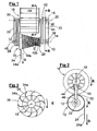
- the windage brake shown therein comprises a spool 10 mounted on a spindle 12 to be rotatable about a first axis 14 and a fan 16 mounted on a spindle 18 to be rotatable about a second axis 20 parallel to the first axis 14.
- the spindles 12 and 18 extend between a pair of end plates 22 thereby forming a frame to carry the windage brake.
- a line 24 having a free end 24a is wound helically upon the spool 10, its other end being secured to the spool 10 by a clamp 26.
- the line 24 is a braid of gel-spun polyethylene filaments with high strength, high modulus and low creep available under the registered trade mark Dyneema from DSM of The Netherlands.
- first drive pulley 28 Secured to one end (the left hand end as seen in Figure 1 ) of the spool 10 and rotatable about the spindle 12 is a first drive pulley 28. Secured to the left hand end of the fan 16 and rotatable therewith about the spindle 18 is a second drive pulley 30.
- a pair of drive belts 32 interconnect the pulleys 28 and 30 so that the fan 16 rotates when the spool 10 rotates.
- the drive belts 32 are toothed belts and the pulleys 28 and 30 appropriately formed therefor.
- an idler wheel bears on each drive belt 32 and is movable arcuately to adjust the tension thereof.
- the line 24 When the free end 24a of the line is pulled, the line 24 is progressively drawn off the spool 10, causing it to rotate about the spindle 12 in the direction of arrow D.
- the drive belts 32 then drive the fan 16 rotatably about the spindle 18 in the direction of arrow E, ie in the same direction of rotation as the spool 10 (which for convenience may be regarded as the forward direction)
- the fan 16 has a generally cylindrical periphery about the axis 20 with a plurality of vanes spaced around this periphery, a representative vane of such plurality being identified in the drawing by reference numeral 34.
- the vane 34 (and each of the vanes) has at its tip a leading edge 34a which is generally tangential of the cylindrical periphery 36 and at its root a trailing edge 34b which is generally radial and is curved forwards (in the direction of rotation of the fan as indicated by arrow E).
- the fan 16 acts as a radial flow air impeller.
- the design of this impeller is such as to give rise to considerable windage.
- the forward curvature of the vanes is such that the exit speed of air from the fan 16 is considerably greater than the tip speed of the fan 16.
- the essential function of the fan 16 in the present invention is that the windage caused by rotation of the fan 16 (in the forward direction) acts as a retarding force on the (forward) rotation of the spool 10. Thus the line 24 is braked.
- the use of forwardly curved vanes delivers a retarding force which may be twice as much as a fan with simple radial vanes.
- the spool 10 has a taper 10a extending (towards the right as seen in Figure 1 ) from a relatively large diameter part to a relatively small diameter part.
- the line 24 acts on a progressively smaller diameter as it unwinds along the taper 10a, thereby accelerating the spool 10.
- the rotation of the spool 10 is relatively slow, and therefore the rotation of the fan 16 is similarly slow and its windage braking force low.
- the spool 10 accelerates, the fan 16 similarly accelerates, and the windage braking force increases.
- the spool continues with a generally cylindrical portion 10b, where drawing off the line 24 at a constant rate rotates the spool 10 at a constant speed, so that the fan 16 also rotates at a constant speed and generates a constant windage braking force.
- Dyneema line facilitates a steep angle on the taper 10a and a small final diameter, both of which contribute to a compact arrangement.
- Dyneema line is also strong and has good wear resistance, contributing to safety.
- the drive pulley 28 secured to the spool 10 has a working diameter larger than that of the drive pulley 30 secured to the fan 16. This provides another adjustment to the speed of the fan 16, which will be understood to rotate faster than the spool 10. Insofar as windage of the fan 16 depends upon its speed of rotation, it follows that this arrangement allows a smaller fan 16 to be used for a given windage braking force. It is also to be understood that either or both of the pulleys 28 and 30 may be replaced by pulleys of different working diameters, allowing the rotational speeds and braking force to be varied.
- the spool 10 has a hub 38 rotatable with the spool 10.
- An arbor 40 At the right hand end of the fan 16 but free therefrom is an arbor 40.
- a retrieve drive belt 42 extends between two pulleys respectively secured to the hub 38 and the arbor 40.
- a resilent strip of spring steel 44 is loosely coiled spirally in one direction around the arbor 40 and extends therefrom to the hub 38.
- the resilient strip 42 is tightly coiled spirally around the hub 38 in the opposite direction from the spiral winding on the arbor 40.
- the resilient strip 42 provides a power spring which is wound as the line 24 is drawn off from the spool 10.
- the spool 10 is formed with a helical channel 50 to guide the line 24, part of which channel 50 is shown diagrammatically in Figure 5 .
- the fan descender is not shown in the drawing, but it comprises a tower with an elevated platform and means enabling persons to climb to the platform from where they are to jump.
- the assembly heretofore described is secured at an elevated position on the tower, conveniently by means of karabiners (not shown) secured to a holdfast and engaged in holes 46 in the end plates 22 of the assembly.
- a harness not shown is secured to the free end 24a of the line 24 and the jumper puts on this harness. (It will be appreciated that various safety precautions are taken, but it is not considered necessary to detail them here).
- the jumper When ready, the jumper jumps off the platform, causing the line 24 to be drawn off the spool 10, rotating the spool 10 and the fan 16. Initially, the line 24 being drawn off from the large diameter part of the spool 10, the windage braking force is low, and the jumper descends at a speed approaching free fall. As the line 24 unwinds down the taper 10a, the effective diameter of the spool 10a decreases, the fan 16 accelerates and the windage braking force increases. Thus the descent of the jumper is progressively slowed. After the line 24 reaches the bottom of the taper 10a, the jumper descends at a steady terminal rate as the line unwinds along the cylindrical portion 10b of the spool 10.
- the terminal rate of descent is determined (with, at least, empirical checks) to be slow enough for the jumper to land on the ground safely - at a vertical speed of not more than 3m/s for a person weighing 150kg.
- the line 24 is long enough to allow the jumper to reach the ground.
- Each jump activates an electronic counter illustrated diagrammatically at 48 in Figure 1 , whereby the number of jumps is recorded.
- the operator of a fan descender embodying the invention can pay for it in relation to its utilisation and maintenance can also be related to the amount of use.
- Figure 6 illustrates a modified form of the invention in which the arbor 40 is offset from the spindle 18 of the fan 16. Among other things this allows the spool 10 to be lengthened, and thereby carry more cable 24 for a greater drop, without increasing the overall length of the machine.
- a plurality of retractor springs 44 may be provided, to increase the strength and speed of retrieval of the cable 24.
- the spool 10 may be formed with another cylindrical section to the left of the tapered section10a as viewed in Figure 1 , and two or more fans 16 may be provided.
- the retrieval mechanism may comprise an electric motor.
- the invention may be applied to a zip wire or other facilities for recreational, educational, training or safety purposes.
- the invention may be adapted to provide safety apparatus for a climber, who can be clipped into the described harness on the ground and then make an ascent (of a tower or climbing wall, say) knowing that he will be lowered safely to the ground if he should fall.
- the invention has been described and illustrated with belts for driving the fan and retrieving the line, but some other mechanism such as gears or chains may otherwise be used.
Landscapes
- Health & Medical Sciences (AREA)
- General Health & Medical Sciences (AREA)
- Life Sciences & Earth Sciences (AREA)
- Biophysics (AREA)
- Orthopedic Medicine & Surgery (AREA)
- Physical Education & Sports Medicine (AREA)
- Mechanical Engineering (AREA)
- Business, Economics & Management (AREA)
- Emergency Management (AREA)
- Engineering & Computer Science (AREA)
- Structures Of Non-Positive Displacement Pumps (AREA)
- Braking Arrangements (AREA)
- Tension Adjustment In Filamentary Materials (AREA)
- Iron Core Of Rotating Electric Machines (AREA)
Claims (20)
- Eine Luftbremse, bestehend aus: einer Spule (10), die zur Rotation um eine erste Achse (14) montiert ist, einem Seil (24), das spiralförmig um die Spule (10) gewickelt ist und ein freies sich von dem Seil erstreckendes Ende (24a) aufweist, und einem von der Spule (10) angetriebenen Ventilator (16), dessen Rotation erfolgt, wenn das Seil (24) an seinem freien Ende (24a) von der Spule (10) gezogen wird, um die Rotationsgeschwindigkeit der Spule (10) und damit die Geschwindigkeit zu begrenzen, in der das Seil (24) von der Spule (10) gezogen wird, dadurch gekennzeichnet, dass die Luftbremse einen Rückzugsmechanismus (38, 40, 44) zum Zurückspulen des Seils (24) auf die Spule (10) aufweist, wenn das freie Ende (24a) des Seils (24) freigegeben wird, und dass die Spule (10) sich entlang der besagten ersten Achse (14) verjüngt.
- Eine Luftbremse gemäß Anspruch 1, dadurch gekennzeichnet, dass die besagte Vorrichtung eine Pluralität besagter Ventilatoren aufweist, die jeweils von der besagten Spule (10) angetrieben werden.
- Eine Luftbremse gemäß Anspruch 1 oder Anspruch 2, dadurch gekennzeichnet, dass der Rückzugsmechanismus eine Rückspulfeder (44) aufweist, die mit einer federelastischen Kraft beaufschlagt wird, wenn die Spule (10) durch Abziehen des Seils (24) rotiert, und das Seil (24) auf die Spule (10) zurückzuzieht, wenn das freie Ende (24a) des Seils (24) freigegeben wird.
- Eine Luftbremse gemäß Anspruch 3, dadurch gekennzeichnet, dass die besagte Vorrichtung eine Pluralität besagter Rückspulfedern aufweist.
- Eine Luftbremse gemäß Anspruch 3 oder Anspruch 4, dadurch gekennzeichnet, dass es sich bei der Rückspulfeder (44) oder bei jeder der Rückspulfedern um eine Trieb- und Aufzugsfeder handelt.
- Eine Luftbremse gemäß Anspruch 3 bis Anspruch 5, dadurch gekennzeichnet, dass die Rückspulfeder (44) oder jede der Rückspulfedern ein elastisches Band aufweist, das spiralförmig um einen koaxial zum Ventilator (16) angeordneten Dorn (40) gewickelt ist, wobei das elastische Band sich von dem Dorn (40) zu einer Nabe (38) erstreckt, auf die es spiralförmig gewickelt wird, wenn das Seil (24) von der Spule (10) gezogen wird.
- Eine Luftbremse gemäß Anspruch 6, dadurch gekennzeichnet, dass die spiralförmige Aufwicklung des elastischen Bandes auf die Nabe (38) in einer entgegengesetzten Richtung zu dessen Aufwicklung auf den Dorn (40) erfolgt.
- Eine Luftbremse gemäß einem der vorhergehenden Ansprüche, dadurch gekennzeichnet, dass die Spule (10) mit einem spiralförmigen Führung (50) für das Seil (24) ausgebildet ist.
- Eine Luftbremse gemäß einem der vorhergehenden Ansprüche, dadurch gekennzeichnet, dass der Ventilator (16) um eine zweite Achse (20) drehbar ist und dass ein Antriebsmechanismus zwischen der Spule (10) und dem Ventilator (16) vorhanden ist, der die Rotation des Ventilators (16) veranlasst, wenn das freie Ende (24a) des Seils (24) von der Spule (10) gezogen wird.
- Eine Luftbremse gemäß Anspruch 9, dadurch gekennzeichnet, dass die Spule (10) eine Verjüngung (10a) entlang der ersten Achse (14) aufweist, die sich von einem Abschnitt mit einem relativ großen Durchmesser zu einem Abschnitt mit einem relativ kleinen Durchmesser erstreckt, und dass sich das freie Ende (24a) des Seils (24) anfangs von dem Abschnitt der Spule (10) mit einem großen Durchmesser ausgehend erstreckt und das Seil (24) bei der Benutzung nach unten zu der Verjüngung (10a) gezogen wird.
- Eine Luftbremse gemäß Anspruch 9 oder Anspruch 10, dadurch gekennzeichnet, dass die zweite Achse (20) parallel zur ersten Achse (14) verläuft.
- Eine Luftbremse gemäß einem der Ansprüche 9 bis 11, dadurch gekennzeichnet, dass der Antriebsmechanismus einen oder mehrere Antriebsriemen (32, 42) aufweist, wobei mindestens einer der besagten Antriebsriemen eine erste mit der Spule (10) verbundene Antriebsscheibe (28) und eine zweite mit dem Ventilator (16) verbundene Antriebsscheibe (30) verbindet und die erste Antriebsscheibe (28) einen größeren Arbeitsdurchmesser hat als die zweite Antriebsscheibe (30).
- Eine Luftbremse gemäß Anspruch 12, dadurch gekennzeichnet, dass mindestens eine der besagten Antriebsscheiben (28, 30) durch eine Antriebsscheibe mit einem unterschiedlichen Arbeitsdurchmesser ersetzt werden kann.
- Eine Luftbremse gemäß einem der vorhergehenden Ansprüche, dadurch gekennzeichnet, dass der Ventilator (16) ein Radial-Ventilator-Laufrad beinhaltet.
- Eine Luftbremse gemäß Anspruch 14, dadurch gekennzeichnet, dass das Laufrad eine Pluralität von Flügeln (34) aufweist, die um einen im Allgemeinen zylindrischen Umfang (36) angeordnet sind, der die Achse des Ventilators (16) begrenzt, wobei jeder Flügel (34) nach vorn und in Drehrichtung des Ventilators (16) gewölbt ist, sich von dessen Wurzel zu dessen Spitze erstreckt und an der Spitze eine Vorderkante (34a) aufweist, die im Wesentlichen tangential zu dem Umfang (36) verläuft, und an der Wurzel eine Hinterkante (34b) aufweist, die im Wesentlichen radial dazu verläuft.
- Eine Luftbremse gemäß Anspruch 14 oder Anspruch 15, dadurch gekennzeichnet, dass der Ventilator (16) so konfiguriert und arrangiert ist, dass die Luft mit einer Geschwindigkeit aus dem Ventilator austritt, die größerer ist als die Umfangsgeschwindigkeit des Ventilators (16).
- Eine Luftbremse gemäß einem der vorhergehenden Ansprüche, dadurch gekennzeichnet, dass das Seil (24) ein Geflecht aus im Gelspinnverfahren gesponnenen Polyethylenfasern mit hoher Stärke, einem hohen Modul und mit geringer Kriechdehnung aufweist.
- Eine Luftbremse gemäß Anspruch 1, dadurch gekennzeichnet, dass der Rückzugsmechanismus einen Elektromotor aufweist.
- Reguliervorrichtung zur Regulierung des Abstiegs einer Person von einer erhöhten Position, dadurch gekennzeichnet, dass die Reguliervorrichtung eine Luftbremse gemäß eines der vorhergehenden Ansprüche aufweist, wobei die Reguliervorrichtung von einem Rahmen (12, 18, 22) zur Sicherung der in der erhöhten Position montierten Vorrichtung getragen wird und am freien Ende (24a) des Seils (24) ein Gurt zur Befestigung des Seils (24) an einer Person vorgesehen ist.
- Reguliervorrichtung gemäß Anspruch 19, dadurch gekennzeichnet, dass die besagte Vorrichtung einen Zähler (48) aufweist, der erfasst, wie oft das Seil (24) von der Spule (10) gezogen wird.
Applications Claiming Priority (2)
| Application Number | Priority Date | Filing Date | Title |
|---|---|---|---|
| GB0605563A GB2436324A (en) | 2006-03-20 | 2006-03-20 | Windage Braking |
| PCT/GB2007/000989 WO2007107746A1 (en) | 2006-03-20 | 2007-03-20 | Windage braking |
Publications (2)
| Publication Number | Publication Date |
|---|---|
| EP1996296A1 EP1996296A1 (de) | 2008-12-03 |
| EP1996296B1 true EP1996296B1 (de) | 2010-08-18 |
Family
ID=36293101
Family Applications (1)
| Application Number | Title | Priority Date | Filing Date |
|---|---|---|---|
| EP07732081A Active EP1996296B1 (de) | 2006-03-20 | 2007-03-20 | Luftbremse |
Country Status (8)
| Country | Link |
|---|---|
| US (1) | US8061483B2 (de) |
| EP (1) | EP1996296B1 (de) |
| AT (1) | ATE477837T1 (de) |
| AU (1) | AU2007228630B2 (de) |
| DE (1) | DE602007008534D1 (de) |
| ES (1) | ES2352661T3 (de) |
| GB (1) | GB2436324A (de) |
| WO (1) | WO2007107746A1 (de) |
Families Citing this family (14)
| Publication number | Priority date | Publication date | Assignee | Title |
|---|---|---|---|---|
| US20050023085A1 (en) * | 2003-07-30 | 2005-02-03 | Munton Timothy John | Lifesaver apparatus |
| US8499890B2 (en) * | 2007-07-18 | 2013-08-06 | Rescue Reel, Llc | Personal escape device |
| GB0910998D0 (en) | 2009-06-24 | 2009-08-05 | Drop Zone Uk Ltd | Regulated descender |
| US8061777B2 (en) * | 2009-10-30 | 2011-11-22 | Ford Global Technologies, Llc | System for seat-actuated head rest extension and retraction |
| USD725831S1 (en) * | 2012-04-24 | 2015-03-31 | Evacuator International Property B.V. | Descent device |
| NL2011303C2 (nl) * | 2013-08-14 | 2015-02-19 | Lely Patent Nv | Slijtvaste veevoergrijpbek. |
| US20150307197A1 (en) * | 2014-04-28 | 2015-10-29 | Capewell Systems Llc | Multi-Use Emergency Descent Device |
| ES2840098T3 (es) | 2015-02-20 | 2021-07-06 | Bungy New Zealand Ltd | Aparato y método de control del movimiento de objetos |
| US10266266B2 (en) | 2016-05-23 | 2019-04-23 | Wing Aviation Llc | Payload delivery system with removable spool |
| BR102016014608B1 (pt) * | 2016-06-21 | 2020-01-21 | Carlos Alberto Leopoldo Da Camara Filho | sistema de dispositivo de exercício |
| GB202102597D0 (en) * | 2021-02-25 | 2021-04-07 | Du Cane Peter | Apparatus for braking the movement of a person through the air |
| US11458346B1 (en) * | 2022-01-05 | 2022-10-04 | Strength Technology LLC | Portable and variable exercise device |
| US12440718B2 (en) * | 2022-01-05 | 2025-10-14 | Blix Strength LLC | Portable and variable exercise device |
| CN115888011B (zh) * | 2022-12-19 | 2026-01-16 | 常州固立高端装备创新中心有限公司 | 一种力量训练机绕线装置及其设计方法 |
Family Cites Families (15)
| Publication number | Priority date | Publication date | Assignee | Title |
|---|---|---|---|---|
| US295047A (en) * | 1884-03-11 | Fire-escape | ||
| US197899A (en) * | 1877-12-04 | Improvement in fire-escapes | ||
| US3789511A (en) * | 1972-02-04 | 1974-02-05 | Columbia Gas Syst Service Corp | Apparatus for sensing a curvature in a conduit |
| NL164207C (nl) * | 1974-07-18 | 1980-12-15 | Lassche Jakob | Ontsnappingsinrichting voorzien van een op een haspel gewikkelde lange lijn, met de haspel gekoppeld opwindmechanisme en een van een vrijloop voorziene vertragingsinrichting. |
| US4088201A (en) * | 1976-06-21 | 1978-05-09 | Macfarlane James L | Portable fire escape |
| US4469196A (en) * | 1982-09-30 | 1984-09-04 | Charlton Sadler | Fire escape device |
| US4442918A (en) * | 1983-06-15 | 1984-04-17 | X-Pert Well Service, Inc. | Emergency escape device |
| US5259433A (en) * | 1989-12-21 | 1993-11-09 | Hermel Cloutier | Door counterweight system |
| US5348116A (en) * | 1992-08-12 | 1994-09-20 | Pickering Gregory R | Rescue system |
| GB2319232A (en) | 1996-11-11 | 1998-05-20 | Gordon Warwick Bendall | Free fall simulator |
| WO2003033074A1 (en) * | 2001-10-15 | 2003-04-24 | Moshe Meller | Method and apparatus for rescuing occupants from high rise buildings using replaceable cable cartridges and dynamic resistance device |
| US6793038B2 (en) * | 2001-10-15 | 2004-09-21 | Moshe Meller | Method and apparatus for rescuing occupants from high structures using replaceable cable cartridges and dynamic resistance device |
| US6962235B2 (en) * | 2003-02-21 | 2005-11-08 | Life-Pack Technologies, Inc. | Apparatus for exterior evacuation from buildings |
| US20060000675A1 (en) * | 2003-12-02 | 2006-01-05 | Penn Jay P | Platform lift apparatus for attic storage space |
| US20060118060A1 (en) * | 2004-12-03 | 2006-06-08 | Ingraham Christopher A | Bird deterrent apparatus |
-
2006
- 2006-03-20 GB GB0605563A patent/GB2436324A/en not_active Withdrawn
-
2007
- 2007-03-20 AT AT07732081T patent/ATE477837T1/de active
- 2007-03-20 EP EP07732081A patent/EP1996296B1/de active Active
- 2007-03-20 DE DE602007008534T patent/DE602007008534D1/de active Active
- 2007-03-20 ES ES07732081T patent/ES2352661T3/es active Active
- 2007-03-20 AU AU2007228630A patent/AU2007228630B2/en not_active Ceased
- 2007-03-20 US US11/725,545 patent/US8061483B2/en not_active Expired - Fee Related
- 2007-03-20 WO PCT/GB2007/000989 patent/WO2007107746A1/en not_active Ceased
Also Published As
| Publication number | Publication date |
|---|---|
| WO2007107746A1 (en) | 2007-09-27 |
| GB2436324A (en) | 2007-09-26 |
| GB0605563D0 (en) | 2006-04-26 |
| US8061483B2 (en) | 2011-11-22 |
| ATE477837T1 (de) | 2010-09-15 |
| DE602007008534D1 (de) | 2010-09-30 |
| AU2007228630A1 (en) | 2007-09-27 |
| EP1996296A1 (de) | 2008-12-03 |
| US20070240940A1 (en) | 2007-10-18 |
| AU2007228630B2 (en) | 2012-04-26 |
| ES2352661T3 (es) | 2011-02-22 |
Similar Documents
| Publication | Publication Date | Title |
|---|---|---|
| EP1996296B1 (de) | Luftbremse | |
| US10022570B2 (en) | Personal escape device with eddy current braking | |
| US2680593A (en) | Escape device | |
| US4448284A (en) | People rescue device | |
| EP2777771B1 (de) | Sturzschutzvorrichtung mit einem Bremsmechanismus | |
| US3188052A (en) | Lowering apparatus | |
| JPS5915654B2 (ja) | 避難装置 | |
| TWI668030B (zh) | 繞繩下降裝置 | |
| US20040055824A1 (en) | Escape-Right | |
| US6182789B1 (en) | Escape device | |
| CN108619622B (zh) | 一种保护人体的下降器 | |
| US20050023085A1 (en) | Lifesaver apparatus | |
| EP2266667A1 (de) | Reguliertes Abseilgerät | |
| EP4049735A1 (de) | Vorrichtung zum abbremsen der bewegung einer person durch die luft | |
| CN112755541A (zh) | 可控速降装置 | |
| GB2606827A (en) | Apparatus for braking the movement of a person through the air | |
| FR3033251A1 (fr) | Treuil d'evacuation en va-et-vient | |
| CN221998681U (zh) | 超高层建筑逃生装置 | |
| WO2009072828A2 (en) | Non-power apparatus for controlling descent | |
| CN209033583U (zh) | 一种带有辅助减速装置的缓降设备 | |
| JPH03184568A (ja) | 緊急時脱出装置 | |
| CN219429590U (zh) | 一种防坠落慢速卷扬机 | |
| CN113401762B (zh) | 限速器绳张紧装置及其使用方法 | |
| US20240285981A1 (en) | Controlled descent safety systems and methods | |
| US20150307197A1 (en) | Multi-Use Emergency Descent Device |
Legal Events
| Date | Code | Title | Description |
|---|---|---|---|
| PUAI | Public reference made under article 153(3) epc to a published international application that has entered the european phase |
Free format text: ORIGINAL CODE: 0009012 |
|
| 17P | Request for examination filed |
Effective date: 20080926 |
|
| AK | Designated contracting states |
Kind code of ref document: A1 Designated state(s): AT BE BG CH CY CZ DE DK EE ES FI FR GB GR HU IE IS IT LI LT LU LV MC MT NL PL PT RO SE SI SK TR |
|
| RTI1 | Title (correction) |
Free format text: WINDAGE BRAKE |
|
| GRAP | Despatch of communication of intention to grant a patent |
Free format text: ORIGINAL CODE: EPIDOSNIGR1 |
|
| DAX | Request for extension of the european patent (deleted) | ||
| GRAS | Grant fee paid |
Free format text: ORIGINAL CODE: EPIDOSNIGR3 |
|
| GRAA | (expected) grant |
Free format text: ORIGINAL CODE: 0009210 |
|
| AK | Designated contracting states |
Kind code of ref document: B1 Designated state(s): AT BE BG CH CY CZ DE DK EE ES FI FR GB GR HU IE IS IT LI LT LU LV MC MT NL PL PT RO SE SI SK TR |
|
| REG | Reference to a national code |
Ref country code: GB Ref legal event code: FG4D |
|
| REG | Reference to a national code |
Ref country code: CH Ref legal event code: EP |
|
| REG | Reference to a national code |
Ref country code: IE Ref legal event code: FG4D |
|
| REF | Corresponds to: |
Ref document number: 602007008534 Country of ref document: DE Date of ref document: 20100930 Kind code of ref document: P |
|
| REG | Reference to a national code |
Ref country code: NL Ref legal event code: T3 |
|
| REG | Reference to a national code |
Ref country code: CH Ref legal event code: NV Representative=s name: KEMIA SA |
|
| LTIE | Lt: invalidation of european patent or patent extension |
Effective date: 20100818 |
|
| PG25 | Lapsed in a contracting state [announced via postgrant information from national office to epo] |
Ref country code: LT Free format text: LAPSE BECAUSE OF FAILURE TO SUBMIT A TRANSLATION OF THE DESCRIPTION OR TO PAY THE FEE WITHIN THE PRESCRIBED TIME-LIMIT Effective date: 20100818 Ref country code: FI Free format text: LAPSE BECAUSE OF FAILURE TO SUBMIT A TRANSLATION OF THE DESCRIPTION OR TO PAY THE FEE WITHIN THE PRESCRIBED TIME-LIMIT Effective date: 20100818 |
|
| REG | Reference to a national code |
Ref country code: ES Ref legal event code: FG2A Effective date: 20110210 |
|
| PG25 | Lapsed in a contracting state [announced via postgrant information from national office to epo] |
Ref country code: SI Free format text: LAPSE BECAUSE OF FAILURE TO SUBMIT A TRANSLATION OF THE DESCRIPTION OR TO PAY THE FEE WITHIN THE PRESCRIBED TIME-LIMIT Effective date: 20100818 Ref country code: PT Free format text: LAPSE BECAUSE OF FAILURE TO SUBMIT A TRANSLATION OF THE DESCRIPTION OR TO PAY THE FEE WITHIN THE PRESCRIBED TIME-LIMIT Effective date: 20101220 Ref country code: BG Free format text: LAPSE BECAUSE OF FAILURE TO SUBMIT A TRANSLATION OF THE DESCRIPTION OR TO PAY THE FEE WITHIN THE PRESCRIBED TIME-LIMIT Effective date: 20101118 Ref country code: CY Free format text: LAPSE BECAUSE OF FAILURE TO SUBMIT A TRANSLATION OF THE DESCRIPTION OR TO PAY THE FEE WITHIN THE PRESCRIBED TIME-LIMIT Effective date: 20100818 Ref country code: IS Free format text: LAPSE BECAUSE OF FAILURE TO SUBMIT A TRANSLATION OF THE DESCRIPTION OR TO PAY THE FEE WITHIN THE PRESCRIBED TIME-LIMIT Effective date: 20101218 Ref country code: PL Free format text: LAPSE BECAUSE OF FAILURE TO SUBMIT A TRANSLATION OF THE DESCRIPTION OR TO PAY THE FEE WITHIN THE PRESCRIBED TIME-LIMIT Effective date: 20100818 |
|
| PG25 | Lapsed in a contracting state [announced via postgrant information from national office to epo] |
Ref country code: SE Free format text: LAPSE BECAUSE OF FAILURE TO SUBMIT A TRANSLATION OF THE DESCRIPTION OR TO PAY THE FEE WITHIN THE PRESCRIBED TIME-LIMIT Effective date: 20100818 Ref country code: GR Free format text: LAPSE BECAUSE OF FAILURE TO SUBMIT A TRANSLATION OF THE DESCRIPTION OR TO PAY THE FEE WITHIN THE PRESCRIBED TIME-LIMIT Effective date: 20101119 Ref country code: LV Free format text: LAPSE BECAUSE OF FAILURE TO SUBMIT A TRANSLATION OF THE DESCRIPTION OR TO PAY THE FEE WITHIN THE PRESCRIBED TIME-LIMIT Effective date: 20100818 |
|
| PG25 | Lapsed in a contracting state [announced via postgrant information from national office to epo] |
Ref country code: DK Free format text: LAPSE BECAUSE OF FAILURE TO SUBMIT A TRANSLATION OF THE DESCRIPTION OR TO PAY THE FEE WITHIN THE PRESCRIBED TIME-LIMIT Effective date: 20100818 |
|
| PG25 | Lapsed in a contracting state [announced via postgrant information from national office to epo] |
Ref country code: RO Free format text: LAPSE BECAUSE OF FAILURE TO SUBMIT A TRANSLATION OF THE DESCRIPTION OR TO PAY THE FEE WITHIN THE PRESCRIBED TIME-LIMIT Effective date: 20100818 Ref country code: EE Free format text: LAPSE BECAUSE OF FAILURE TO SUBMIT A TRANSLATION OF THE DESCRIPTION OR TO PAY THE FEE WITHIN THE PRESCRIBED TIME-LIMIT Effective date: 20100818 Ref country code: SK Free format text: LAPSE BECAUSE OF FAILURE TO SUBMIT A TRANSLATION OF THE DESCRIPTION OR TO PAY THE FEE WITHIN THE PRESCRIBED TIME-LIMIT Effective date: 20100818 Ref country code: CZ Free format text: LAPSE BECAUSE OF FAILURE TO SUBMIT A TRANSLATION OF THE DESCRIPTION OR TO PAY THE FEE WITHIN THE PRESCRIBED TIME-LIMIT Effective date: 20100818 |
|
| PLBE | No opposition filed within time limit |
Free format text: ORIGINAL CODE: 0009261 |
|
| STAA | Information on the status of an ep patent application or granted ep patent |
Free format text: STATUS: NO OPPOSITION FILED WITHIN TIME LIMIT |
|
| 26N | No opposition filed |
Effective date: 20110519 |
|
| REG | Reference to a national code |
Ref country code: DE Ref legal event code: R097 Ref document number: 602007008534 Country of ref document: DE Effective date: 20110519 |
|
| PG25 | Lapsed in a contracting state [announced via postgrant information from national office to epo] |
Ref country code: MC Free format text: LAPSE BECAUSE OF NON-PAYMENT OF DUE FEES Effective date: 20110331 |
|
| PG25 | Lapsed in a contracting state [announced via postgrant information from national office to epo] |
Ref country code: MT Free format text: LAPSE BECAUSE OF FAILURE TO SUBMIT A TRANSLATION OF THE DESCRIPTION OR TO PAY THE FEE WITHIN THE PRESCRIBED TIME-LIMIT Effective date: 20100818 |
|
| REG | Reference to a national code |
Ref country code: IE Ref legal event code: MM4A |
|
| PG25 | Lapsed in a contracting state [announced via postgrant information from national office to epo] |
Ref country code: IE Free format text: LAPSE BECAUSE OF NON-PAYMENT OF DUE FEES Effective date: 20110320 |
|
| PGFP | Annual fee paid to national office [announced via postgrant information from national office to epo] |
Ref country code: AT Payment date: 20120319 Year of fee payment: 6 |
|
| PG25 | Lapsed in a contracting state [announced via postgrant information from national office to epo] |
Ref country code: LU Free format text: LAPSE BECAUSE OF NON-PAYMENT OF DUE FEES Effective date: 20110320 |
|
| PGFP | Annual fee paid to national office [announced via postgrant information from national office to epo] |
Ref country code: ES Payment date: 20120326 Year of fee payment: 6 |
|
| PG25 | Lapsed in a contracting state [announced via postgrant information from national office to epo] |
Ref country code: TR Free format text: LAPSE BECAUSE OF FAILURE TO SUBMIT A TRANSLATION OF THE DESCRIPTION OR TO PAY THE FEE WITHIN THE PRESCRIBED TIME-LIMIT Effective date: 20100818 |
|
| PG25 | Lapsed in a contracting state [announced via postgrant information from national office to epo] |
Ref country code: HU Free format text: LAPSE BECAUSE OF FAILURE TO SUBMIT A TRANSLATION OF THE DESCRIPTION OR TO PAY THE FEE WITHIN THE PRESCRIBED TIME-LIMIT Effective date: 20100818 |
|
| REG | Reference to a national code |
Ref country code: AT Ref legal event code: MM01 Ref document number: 477837 Country of ref document: AT Kind code of ref document: T Effective date: 20130320 |
|
| PG25 | Lapsed in a contracting state [announced via postgrant information from national office to epo] |
Ref country code: AT Free format text: LAPSE BECAUSE OF NON-PAYMENT OF DUE FEES Effective date: 20130320 |
|
| REG | Reference to a national code |
Ref country code: ES Ref legal event code: FD2A Effective date: 20150424 |
|
| PGFP | Annual fee paid to national office [announced via postgrant information from national office to epo] |
Ref country code: NL Payment date: 20150319 Year of fee payment: 9 Ref country code: IT Payment date: 20150225 Year of fee payment: 9 |
|
| PGFP | Annual fee paid to national office [announced via postgrant information from national office to epo] |
Ref country code: BE Payment date: 20150319 Year of fee payment: 9 |
|
| PG25 | Lapsed in a contracting state [announced via postgrant information from national office to epo] |
Ref country code: ES Free format text: LAPSE BECAUSE OF NON-PAYMENT OF DUE FEES Effective date: 20140321 |
|
| PGFP | Annual fee paid to national office [announced via postgrant information from national office to epo] |
Ref country code: CH Payment date: 20150630 Year of fee payment: 9 |
|
| REG | Reference to a national code |
Ref country code: FR Ref legal event code: PLFP Year of fee payment: 10 |
|
| PG25 | Lapsed in a contracting state [announced via postgrant information from national office to epo] |
Ref country code: BE Free format text: LAPSE BECAUSE OF NON-PAYMENT OF DUE FEES Effective date: 20160331 |
|
| REG | Reference to a national code |
Ref country code: CH Ref legal event code: PL |
|
| REG | Reference to a national code |
Ref country code: NL Ref legal event code: MM Effective date: 20160401 |
|
| PG25 | Lapsed in a contracting state [announced via postgrant information from national office to epo] |
Ref country code: CH Free format text: LAPSE BECAUSE OF NON-PAYMENT OF DUE FEES Effective date: 20160331 Ref country code: LI Free format text: LAPSE BECAUSE OF NON-PAYMENT OF DUE FEES Effective date: 20160331 Ref country code: NL Free format text: LAPSE BECAUSE OF NON-PAYMENT OF DUE FEES Effective date: 20160401 |
|
| PG25 | Lapsed in a contracting state [announced via postgrant information from national office to epo] |
Ref country code: IT Free format text: LAPSE BECAUSE OF NON-PAYMENT OF DUE FEES Effective date: 20160320 |
|
| REG | Reference to a national code |
Ref country code: FR Ref legal event code: PLFP Year of fee payment: 11 |
|
| REG | Reference to a national code |
Ref country code: FR Ref legal event code: PLFP Year of fee payment: 12 |
|
| PGFP | Annual fee paid to national office [announced via postgrant information from national office to epo] |
Ref country code: FR Payment date: 20230330 Year of fee payment: 17 |
|
| P01 | Opt-out of the competence of the unified patent court (upc) registered |
Effective date: 20230522 |
|
| PGFP | Annual fee paid to national office [announced via postgrant information from national office to epo] |
Ref country code: DE Payment date: 20230330 Year of fee payment: 17 |
|
| REG | Reference to a national code |
Ref country code: DE Ref legal event code: R119 Ref document number: 602007008534 Country of ref document: DE |
|
| PG25 | Lapsed in a contracting state [announced via postgrant information from national office to epo] |
Ref country code: DE Free format text: LAPSE BECAUSE OF NON-PAYMENT OF DUE FEES Effective date: 20241001 |
|
| PG25 | Lapsed in a contracting state [announced via postgrant information from national office to epo] |
Ref country code: FR Free format text: LAPSE BECAUSE OF NON-PAYMENT OF DUE FEES Effective date: 20240331 |
|
| PG25 | Lapsed in a contracting state [announced via postgrant information from national office to epo] |
Ref country code: FR Free format text: LAPSE BECAUSE OF NON-PAYMENT OF DUE FEES Effective date: 20240331 Ref country code: DE Free format text: LAPSE BECAUSE OF NON-PAYMENT OF DUE FEES Effective date: 20241001 |
|
| PGFP | Annual fee paid to national office [announced via postgrant information from national office to epo] |
Ref country code: GB Payment date: 20260129 Year of fee payment: 20 |