EP1995814B1 - Brennstoffzellenstapel - Google Patents
Brennstoffzellenstapel Download PDFInfo
- Publication number
- EP1995814B1 EP1995814B1 EP08163022A EP08163022A EP1995814B1 EP 1995814 B1 EP1995814 B1 EP 1995814B1 EP 08163022 A EP08163022 A EP 08163022A EP 08163022 A EP08163022 A EP 08163022A EP 1995814 B1 EP1995814 B1 EP 1995814B1
- Authority
- EP
- European Patent Office
- Prior art keywords
- stack
- fuel cell
- fuel
- separator
- air
- Prior art date
- Legal status (The legal status is an assumption and is not a legal conclusion. Google has not performed a legal analysis and makes no representation as to the accuracy of the status listed.)
- Expired - Fee Related
Links
Images


Classifications
-
- H—ELECTRICITY
- H01—ELECTRIC ELEMENTS
- H01M—PROCESSES OR MEANS, e.g. BATTERIES, FOR THE DIRECT CONVERSION OF CHEMICAL ENERGY INTO ELECTRICAL ENERGY
- H01M8/00—Fuel cells; Manufacture thereof
- H01M8/04—Auxiliary arrangements, e.g. for control of pressure or for circulation of fluids
-
- H—ELECTRICITY
- H01—ELECTRIC ELEMENTS
- H01M—PROCESSES OR MEANS, e.g. BATTERIES, FOR THE DIRECT CONVERSION OF CHEMICAL ENERGY INTO ELECTRICAL ENERGY
- H01M4/00—Electrodes
- H01M4/86—Inert electrodes with catalytic activity, e.g. for fuel cells
-
- H—ELECTRICITY
- H01—ELECTRIC ELEMENTS
- H01M—PROCESSES OR MEANS, e.g. BATTERIES, FOR THE DIRECT CONVERSION OF CHEMICAL ENERGY INTO ELECTRICAL ENERGY
- H01M8/00—Fuel cells; Manufacture thereof
- H01M8/02—Details
- H01M8/0202—Collectors; Separators, e.g. bipolar separators; Interconnectors
- H01M8/0258—Collectors; Separators, e.g. bipolar separators; Interconnectors characterised by the configuration of channels, e.g. by the flow field of the reactant or coolant
- H01M8/026—Collectors; Separators, e.g. bipolar separators; Interconnectors characterised by the configuration of channels, e.g. by the flow field of the reactant or coolant characterised by grooves, e.g. their pitch or depth
-
- H—ELECTRICITY
- H01—ELECTRIC ELEMENTS
- H01M—PROCESSES OR MEANS, e.g. BATTERIES, FOR THE DIRECT CONVERSION OF CHEMICAL ENERGY INTO ELECTRICAL ENERGY
- H01M8/00—Fuel cells; Manufacture thereof
- H01M8/02—Details
- H01M8/0202—Collectors; Separators, e.g. bipolar separators; Interconnectors
- H01M8/0258—Collectors; Separators, e.g. bipolar separators; Interconnectors characterised by the configuration of channels, e.g. by the flow field of the reactant or coolant
- H01M8/0263—Collectors; Separators, e.g. bipolar separators; Interconnectors characterised by the configuration of channels, e.g. by the flow field of the reactant or coolant having meandering or serpentine paths
-
- H—ELECTRICITY
- H01—ELECTRIC ELEMENTS
- H01M—PROCESSES OR MEANS, e.g. BATTERIES, FOR THE DIRECT CONVERSION OF CHEMICAL ENERGY INTO ELECTRICAL ENERGY
- H01M8/00—Fuel cells; Manufacture thereof
- H01M8/02—Details
- H01M8/0202—Collectors; Separators, e.g. bipolar separators; Interconnectors
- H01M8/0267—Collectors; Separators, e.g. bipolar separators; Interconnectors having heating or cooling means, e.g. heaters or coolant flow channels
-
- H—ELECTRICITY
- H01—ELECTRIC ELEMENTS
- H01M—PROCESSES OR MEANS, e.g. BATTERIES, FOR THE DIRECT CONVERSION OF CHEMICAL ENERGY INTO ELECTRICAL ENERGY
- H01M8/00—Fuel cells; Manufacture thereof
- H01M8/02—Details
- H01M8/0271—Sealing or supporting means around electrodes, matrices or membranes
-
- H—ELECTRICITY
- H01—ELECTRIC ELEMENTS
- H01M—PROCESSES OR MEANS, e.g. BATTERIES, FOR THE DIRECT CONVERSION OF CHEMICAL ENERGY INTO ELECTRICAL ENERGY
- H01M8/00—Fuel cells; Manufacture thereof
- H01M8/04—Auxiliary arrangements, e.g. for control of pressure or for circulation of fluids
- H01M8/04007—Auxiliary arrangements, e.g. for control of pressure or for circulation of fluids related to heat exchange
- H01M8/04014—Heat exchange using gaseous fluids; Heat exchange by combustion of reactants
-
- H—ELECTRICITY
- H01—ELECTRIC ELEMENTS
- H01M—PROCESSES OR MEANS, e.g. BATTERIES, FOR THE DIRECT CONVERSION OF CHEMICAL ENERGY INTO ELECTRICAL ENERGY
- H01M8/00—Fuel cells; Manufacture thereof
- H01M8/04—Auxiliary arrangements, e.g. for control of pressure or for circulation of fluids
- H01M8/04082—Arrangements for control of reactant parameters, e.g. pressure or concentration
- H01M8/04089—Arrangements for control of reactant parameters, e.g. pressure or concentration of gaseous reactants
-
- H—ELECTRICITY
- H01—ELECTRIC ELEMENTS
- H01M—PROCESSES OR MEANS, e.g. BATTERIES, FOR THE DIRECT CONVERSION OF CHEMICAL ENERGY INTO ELECTRICAL ENERGY
- H01M8/00—Fuel cells; Manufacture thereof
- H01M8/24—Grouping of fuel cells, e.g. stacking of fuel cells
- H01M8/241—Grouping of fuel cells, e.g. stacking of fuel cells with solid or matrix-supported electrolytes
-
- H—ELECTRICITY
- H01—ELECTRIC ELEMENTS
- H01M—PROCESSES OR MEANS, e.g. BATTERIES, FOR THE DIRECT CONVERSION OF CHEMICAL ENERGY INTO ELECTRICAL ENERGY
- H01M8/00—Fuel cells; Manufacture thereof
- H01M8/24—Grouping of fuel cells, e.g. stacking of fuel cells
- H01M8/2465—Details of groupings of fuel cells
- H01M8/2483—Details of groupings of fuel cells characterised by internal manifolds
-
- H—ELECTRICITY
- H01—ELECTRIC ELEMENTS
- H01M—PROCESSES OR MEANS, e.g. BATTERIES, FOR THE DIRECT CONVERSION OF CHEMICAL ENERGY INTO ELECTRICAL ENERGY
- H01M8/00—Fuel cells; Manufacture thereof
- H01M8/24—Grouping of fuel cells, e.g. stacking of fuel cells
- H01M8/2465—Details of groupings of fuel cells
- H01M8/2484—Details of groupings of fuel cells characterised by external manifolds
-
- H—ELECTRICITY
- H01—ELECTRIC ELEMENTS
- H01M—PROCESSES OR MEANS, e.g. BATTERIES, FOR THE DIRECT CONVERSION OF CHEMICAL ENERGY INTO ELECTRICAL ENERGY
- H01M8/00—Fuel cells; Manufacture thereof
- H01M8/10—Fuel cells with solid electrolytes
- H01M2008/1095—Fuel cells with polymeric electrolytes
-
- H—ELECTRICITY
- H01—ELECTRIC ELEMENTS
- H01M—PROCESSES OR MEANS, e.g. BATTERIES, FOR THE DIRECT CONVERSION OF CHEMICAL ENERGY INTO ELECTRICAL ENERGY
- H01M8/00—Fuel cells; Manufacture thereof
- H01M8/04—Auxiliary arrangements, e.g. for control of pressure or for circulation of fluids
- H01M8/04007—Auxiliary arrangements, e.g. for control of pressure or for circulation of fluids related to heat exchange
- H01M8/04067—Heat exchange or temperature measuring elements, thermal insulation, e.g. heat pipes, heat pumps, fins
- H01M8/04074—Heat exchange unit structures specially adapted for fuel cell
-
- Y—GENERAL TAGGING OF NEW TECHNOLOGICAL DEVELOPMENTS; GENERAL TAGGING OF CROSS-SECTIONAL TECHNOLOGIES SPANNING OVER SEVERAL SECTIONS OF THE IPC; TECHNICAL SUBJECTS COVERED BY FORMER USPC CROSS-REFERENCE ART COLLECTIONS [XRACs] AND DIGESTS
- Y02—TECHNOLOGIES OR APPLICATIONS FOR MITIGATION OR ADAPTATION AGAINST CLIMATE CHANGE
- Y02E—REDUCTION OF GREENHOUSE GAS [GHG] EMISSIONS, RELATED TO ENERGY GENERATION, TRANSMISSION OR DISTRIBUTION
- Y02E60/00—Enabling technologies; Technologies with a potential or indirect contribution to GHG emissions mitigation
- Y02E60/30—Hydrogen technology
- Y02E60/50—Fuel cells
Definitions
- the present invention relates to a fuel cell stack having an improved cooling structure.
- a fuel cell is an electricity generating system converting chemical reaction energy into electric energy through a reaction between an oxidant such as oxygen and hydrogen contained in a hydrocarbon material such as methanol, ethanol, or natural gas.
- Fuel cells generate electric energy through an electrochemical reaction between a hydrogen-containing material and an oxidant without combustion. The electrochemical reaction also generates heat as a byproduct.
- Illustrative examples of such fuel cells are disclosed in e.g. WO 98/21773 .
- the fuel cells are classified into phosphoric acid fuel cells operating at temperatures ranging from 120°C to 150°C, molten carbonate fuel cells operating at temperatures ranging from 600°C to 700°C, solid oxide fuel cells operating at temperatures above 1,000°C, polymer electrolyte membrane fuel cells (PEMFC) operating at temperatures ranging from room temperature to 100°C or less, and alkaline fuel cells.
- PEMFC polymer electrolyte membrane fuel cells
- the recently developed PEMFC has superior output characteristics, low operating temperatures, and fast starting and response characteristics. So, the PEMFC has a wide range of applications including use in mobile power sources for vehicles, distributed power sources for home or buildings, and small power sources for electronic apparatus.
- the PEMFC includes a stack which is the main body of the fuel cell, a fuel tank, and a fuel pump supplying the fuel from the fuel tank to the stack.
- the PEMFC may further include a reformer for reforming the fuel to generate hydrogen and for supplying the hydrogen to the stack in the course of supplying the fuel stored in the fuel tank to the stack.
- the fuel stored in the fuel tank is supplied to the reformer by a fuel pump.
- the reformer reforms the fuel and generates hydrogen.
- the stack generates electric energy through an electrochemical reaction between the hydrogen and oxygen or some other oxidant.
- a fuel cell system may employ a direct methanol fuel cell (DMFC) where a liquid methanol fuel is directly supplied to the stack.
- DMFC direct methanol fuel cell
- PEMFC does not require a reformer.
- the stack generating electric energy is constructed with several to tens of unit cells each having a membrane-electrode assembly (MEA) and a separator which is also referred to as a bipolar plate in the art.
- MEA membrane-electrode assembly
- the MEA has an anode and a cathode formed on the two surfaces of an electrolyte membrane.
- the unit cells are the electricity generators of the stack.
- the separator serves as a passage through which hydrogen and oxygen needed for reactions of the fuel cell are supplied to the anode and the cathode on the membrane-electrode.
- the separator serves as a conductor serially coupling the anode and the cathode of the MEA.
- the hydrogen-containing fuel is supplied to the anode, and oxygen, oxygen-containing air, or some other oxidant is supplied to the cathode.
- electrochemical oxidation of fuel gas occurs at the anode, and electrochemical reduction of oxygen occurs at the cathode, generating an electron current. Electricity, heat, and water are produced by the electron current.
- the stack must be maintained at a proper operating temperature in order to secure stability of the electrolyte membrane of the MEA and to prevent deterioration in performance of the MEA.
- a stack that is not maintained at proper operating temperatures may be damaged. Therefore, a cooling unit that circulates air or water is also provided that continuously absorbs and releases the heat generated by the stack during the operation of the fuel cell system.
- cooling channels are formed between the separators or in cooling plates that are located between the unit cells.
- the coolant flowing through the cooling channels formed between the separators or in the cooling plates can rapidly dissipate the heat generated from an electrochemical reaction in the unit cells.
- cooling plates located between the unit cells increases the thickness of the fuel cell system.
- cooling plates are not used and the cooling channels are formed between the separators, the thickness of the separators increases, therefore increasing the thickness of the fuel cell system.
- An increase in the volume of the stack limits the capability to design a compact fuel cell system.
- the conventional stack cooling structure must include both an air pump for supplying air containing oxygen to the stack and a cooling fan for supplying a cooling air to the stack, more parts are needed and more power is consumed by the fuel cell system.
- the present invention addresses the problems associated with the conventional stacks, by minimizing the volume of the stack and reducing power consumption as well as the number of components of the fuel cell system.
- a fuel cell stack including an electricity generating assembly having a plurality of unit cells is presented, as defined in the claims.
- Fig. 1 is a block diagram of a fuel cell system.
- Fig. 2 is a block diagram of another fuel cell system.
- Fig. 3 is an exploded perspective view of a first embodiment for a stack of the present invention.
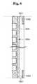
- Fig. 4 is a plan view of the stack shown in Fig. 3 .
- Fig. 5 is an exploded perspective view of a second embodiment for a stack of the present invention.
- Fig. 6 is a partial cross sectional view of the stack shown in Fig. 5 .
- Fig. 1 is a block diagram of a fuel cell system 100.
- the fuel cell system 100 includes a stack 10 constructed by stacking a plurality of unit cells or electricity generators 11 generating electric energy through a chemical reaction between hydrogen and oxygen or another oxidant, a fuel supply unit 30 supplying a hydrogen-containing fuel to the stack 10, and an air supply unit 40 supplying air to the stack 10.
- the fuel supply unit 30 includes a fuel tank 31 storing the fuel, and a fuel pump 33 coupled to the fuel tank 31 to discharge the fuel stored in the fuel tank 31.
- the fuel is supplied from the fuel supply unit 30 through the reformer 20 to the stack 10. Therefore, the reformer 20 is located between the fuel supply unit 30 and the stack 10 and is coupled to the fuel supply unit 30 and the stack 10 through first and second supply lines 91, 92.
- the fuel cell system may be constructed according to a direct oxidation cell scheme where the liquid fuel is directly supplied to the stack 10.
- the reformer 20 is eliminated from the fuel cell system 100 that is constructed according to the PEMFC scheme.
- the fuel cell system used as an exemplary system in the description below is constructed according to the PEMFC scheme.
- the present invention is not limited to fuel cell systems constructed according to this scheme and may be applied to equivalent structures.
- the reformer 20 generates hydrogen from the liquid fuel through a reforming reaction. In addition, the reformer 20 reduces a concentration of carbon monoxide contained in the reformed gas.
- the reformer 20 includes a reforming reactor for reforming the liquid fuel to generate the reformed gas containing hydrogen, and a carbon monoxide reducing section for reducing the concentration of the carbon monoxide in the reformed gas.
- the reforming reactor uses a catalytic reaction such as a steam reforming reaction, a partial oxidation reaction, or an auto-thermal reaction.
- the carbon monoxide reducing section may use a catalytic reaction, such as a water-gas shift (WGS) reaction or a preferential oxidation (PROX) reaction, or it may use a purification reaction of hydrogen with a separating membrane.
- WGS water-gas shift
- PROX preferential oxidation
- the fuel used in the present invention may be a hydrocarbon such as natural gas or an alcohol such as methanol or ethanol. Also, a pure oxygen stored in an additional storage device or oxygen contained in atmospheric air may be used for the reaction.
- the air supply unit 40 is coupled to the stack 10.
- the air supply unit 40 includes an air pump 41 drawing air and supplying it to the stack 10 with a predetermined pumping pressure.
- the air supply unit 40 and the stack 10 are coupled together through a third supply line 93.
- a portion of the air supplied from the air supply unit 40 is used for the electrochemical reaction in the electricity generators 11 and another portion is used to cool the stack 10.
- the fuel cell system 100 does not have any additional devices for cooling the stack 10 aside from the air supply unit 40.
- Fig. 2 is a block diagram of a fuel cell system 200.
- a coolant supply unit 208 is used.
- the fuel cell system 200 includes a stack 204 constructed by a plurality of unit cells or electricity generators 202 generating electric energy through a chemical reaction between hydrogen and oxygen, a fuel supply unit 206 supplying a hydrogen-containing fuel to the electricity generators 202, and a coolant supply unit 208 supplying air as a coolant to the electricity generators 202.
- the fuel cell system 200 does not require an additional air supply unit.
- the coolant supply unit 208 includes a cooling fan 210.
- the cooling fan 210 is coupled to the stack 204 through a fourth supply line 212, so that the coolant can be supplied to the stack 204. Because the coolant must be used also as the oxygen source for the MEA, atmospheric air is used as the coolant.
- the fuel tank 214, the fuel pump 216, and the reformer 218 of this embodiment are similar to those of the embodiment of Fig. 1 and their detailed description is omitted.
- Fig. 3 is an exploded perspective view of the stack 204 shown in Fig. 2 .
- Fig. 4 is a plan view of the stack 204.
- the stack 204 is described with reference to Figs. 2 , 3 , and 4 .
- the stack 10 shown in Fig. 1 has the same structure as the stack 204 shown in Fig. 2 .
- the stack 204 includes a plurality of electricity generators 202 generating electric energy through oxidation and reduction reactions between a reformed gas supplied from the reformer 218 and air.
- Each of the electricity generators 202 is a unit cell generating electric energy.
- Each of the unit cells or electricity generators 202 includes a MEA 202a performing the oxidation and reduction reactions between the hydrogen and the oxygen, and separators 202b, 202c supplying the hydrogen and the oxygen to the MEA 202a.
- the electricity generators 202 are constructed by interposing the MEA 202a between the separators 202b, 202c, including a first separator 202b and a second separator 202c, and attaching the separators 202b, 202c to both sides of the MEA 202a.
- the stack 204 is constructed by sequentially stacking a plurality of the electricity generators 202.
- An anode is formed on one side of the MEA 202a, and a cathode is formed on the other side of the MEA 202a.
- the MEA 202a has an electrolyte membrane between the anode and the cathode.
- the anode receives the reformed gas through the first separator 202b.
- the anode is constructed with a catalyst layer for decomposing the reformed gas into electrons and hydrogen ions and a gas diffusion layer for promoting movement of the electrons and the reformed gas.
- the cathode receives the air through the second separator 202c.
- the cathode is constructed with a catalyst layer facilitating a reaction between the electrons, the hydrogen ions, and oxygen contained in the air, to generate water, and a gas diffusion layer promoting flow of the oxygen.
- the electrolyte membrane is made of a solid polymer electrolyte having a thickness of 50 ⁇ m to 200 ⁇ m.
- the electrolyte membrane has an ion exchange function for moving the hydrogen ions generated by the catalyst layer of the anode into the catalyst layer of the cathode.
- the stack 204 generates electric energy, thermal energy, and water by reactions represented by the following equations: Anode Reaction H 2 ⁇ 2H + + 2e - Cathode Reaction 1 ⁇ 2O 2 + 2H + + 2e - ⁇ H 2 O Overall Reaction H 2 + 1 ⁇ 2O 2 ⁇ H 2 O + (electric current) + (thermal energy)
- the above reactions can be summarized as follows.
- a reformed gas is supplied to the anode of the MEA 202a through a first separator 202b, and air is supplied to the cathode through a second separator 202c. When the reformed gas flows through the anode, hydrogen is decomposed into an electron and a proton (hydrogen ion).
- the first and second separators 202b, 202c serve as conductors which electrically couple the anode and the cathode. They also serve as passages through which the reformed gas and air are supplied to the anodes and the cathodes.
- Gas channels 202d through which the reformed gas flows are formed on one surface of the first separator 202b.
- Air passages 202e through which the air, used for the reaction, and the cooling air, used to cool the heated electricity generators 202, flow are formed on one surface of the second separator 202c.
- the other surfaces of the first and second separators 202b, 202c where the gas channel 202d and the air passages 202e are not formed are attached together to construct the electricity generator 202.
- the cooling air supplied from the coolant supply unit 208 flowing through the air passages 202e can cool the heated electricity generators 202 and supply the air used for the reaction in the MEA 202a. Because, in the stack 204, the air used for the reaction and the cooling air are simultaneously supplied through the air passages 202e, there is no need for conventional cooling structures like cooling channels and cooling plates.
- the overall thickness of the electricity generators 202 can be reduced.
- the thickness of the stack 204 which is a stack of the electricity generators 202, is also reduced.
- the air passages 202e, formed on the second separators 202c, are spaced apart at predetermined intervals.
- the air passages 202e are straight lines extending along a direction from one edge to the other edge of the second separator 202c.
- the air passages 202e are formed on a contacting surface of the second separator 202c and are in contact with the MEA 202a. Both ends of the air passages 202e are exposed to the exterior of the stack 204. One end of each air passage 202e is used as an air inlet, and the other end is used as an air outlet.
- the air passages 202e have a rectangular cross section.
- the invention is not limited to passages of rectangular cross section and the air passages 202e may have cross sections of various shapes including semicircular and trapezoidal cross sections.
- Fig. 5 is an exploded perspective view of an embodiment for a stack 300 of the present invention.
- Fig. 6 is a partial cross sectional view of the stack 300.
- the air passages 202e are constructed by attaching the second separator 202c and the MEA 202a and consist of hollow spaces formed between the second separator 202c and the MEA 202a. In these hollow spaces, the second separator 202c and the MEA 202a are not attached together and cannot support each other. The hollow spaces are usually formed in inactive regions defined on the MEA 202a.
- supporting members 300d are attached to portions of air passages 300c corresponding to inactive regions 300b defined in an MEA 300a.
- the supporting members 300d are in contact with the MEA 300a.
- the supporting members 300d are located along both inlet and outlet ends of the air passages 300c and extend along a direction perpendicular to the air passages 300c.
- Supporting members 300d are mounted on mounting portions 300f that are formed between air passages 300c on the second separator 300e. Depth of the mounting portions 300f corresponds to a thickness of the supporting member 300d.
- the mounting portions 300f are formed at both ends of the air passages 300c, and the supporting members 300d are closely attached to the mounting portions 300f. Therefore, the outer surfaces of the supporting members 300d and the second separators 300e are at the same level and the supporting members 300d can be uniformly attached to the inactive regions 300b of the MEA 300a.
- the stack 204 may get distorted.
- the supporting members 300d make it possible to prevent distortion in the embodiment stack 300 of the invention.
Landscapes
- Chemical & Material Sciences (AREA)
- Engineering & Computer Science (AREA)
- Chemical Kinetics & Catalysis (AREA)
- Electrochemistry (AREA)
- General Chemical & Material Sciences (AREA)
- Life Sciences & Earth Sciences (AREA)
- Manufacturing & Machinery (AREA)
- Sustainable Development (AREA)
- Sustainable Energy (AREA)
- Combustion & Propulsion (AREA)
- Fuel Cell (AREA)
Claims (6)
- Ein Brennstoffzellenstapel (204, 300), der eine Elektrizität generierende Anordnung mit einer Vielzahl von Einheitszellen (202) umfasst und elektrische Energie durch eine elektrochemische Reaktion unter Verwendung eines Brennstoffs und eines Oxidationsmittels generiert, wobei jede Einheitszelle (202) Folgendes umfasst:eine Membran-Elektroden-Anordnung (202a, 300a) mit einer ersten Seite und einer zweiten Seite;einen auf der ersten Seite angeordneten ersten Separator (202b) und einen auf der zweiten Seite der Membran-Elektroden-Anordnung (202a, 300a) angeordneten zweiten Separator (202c, 300e);eine Vielzahl von in dem zweiten Separator (202c, 300e) ausgebildeten Kanälen, wobei die Kanäle der Membran-Elektroden-Anordnung (202a, 300a) zugewandt sind; undeine Vielzahl von von den Kanälen gebildeten Durchgängen (202e, 300c),wobei die Durchgänge (202e, 300c) gemeinsam von dem Oxidationsmittel und einem zum Kühlen des Stapels verwendeten Kühlmittel verwendet werden können, dadurch gekennzeichnet, dass
die Durchgänge (202e, 300c) sich von einer Kante zu einer weiteren Kante des zweiten Separators (202c, 300e) erstrecken und beide Enden jedes Durchgangs (202e, 300c) zur Außenseite des Stapels hin freigelegt sind,
dadurch gekennzeichnet, dass jede Einheitszelle (202) ferner ein Stützelement (300d) umfasst, das an Teilen der Durchgänge (202e, 300c), die einem inaktiven Bereich (300b) der Membran-Elektroden-Anordnung (202a, 300a) entsprechen, angebracht ist. - Der Brennstoffzellenstapel (204, 300) nach Anspruch 1, wobei jeder der Durchgänge (202e, 300c) einen rechteckigen, halbkreisförmigen oder trapezförmigen Querschnitt aufweist.
- Der Brennstoffzellenstapel (204, 300) nach Anspruch 1, wobei die Durchgänge (202e, 300c) gerade Linien sind.
- Der Brennstoffzellenstapel (204, 300) nach Anspruch 1, wobei das Stützelement (300d) so breit wie der inaktive Bereich (300b) der Membran-Elektroden-Anordnung (202a, 300a) ist.
- Der Brennstoffzellenstapel (204, 300) nach Anspruch 1, wobei jede Einheitszelle (202) ferner Montierteile (300f) umfasst, die auf dem zweiten Separator (202c, 300e) zwischen den Kanälen ausgebildet sind, wobei das Stützelement (300d) auf den Montierteilen (300f) montiert ist.
- Der Brennstoffzellenstapel (204, 300) nach Anspruch 5, wobei eine Tiefe des Montierteils (300f) einer Dicke des Stützelements (300d) entspricht.
Applications Claiming Priority (2)
| Application Number | Priority Date | Filing Date | Title |
|---|---|---|---|
| KR1020040074605A KR100637490B1 (ko) | 2004-09-17 | 2004-09-17 | 연료 전지용 스택과 이를 갖는 연료 전지 시스템 |
| EP05108519A EP1641065A3 (de) | 2004-09-17 | 2005-09-16 | Brennstoffzellenstapel und diese enthlatende Brennstoffzellensystem |
Related Parent Applications (2)
| Application Number | Title | Priority Date | Filing Date |
|---|---|---|---|
| EP05108519.9 Division | 2005-09-16 | ||
| EP05108519A Division EP1641065A3 (de) | 2004-09-17 | 2005-09-16 | Brennstoffzellenstapel und diese enthlatende Brennstoffzellensystem |
Publications (3)
| Publication Number | Publication Date |
|---|---|
| EP1995814A2 EP1995814A2 (de) | 2008-11-26 |
| EP1995814A3 EP1995814A3 (de) | 2009-03-25 |
| EP1995814B1 true EP1995814B1 (de) | 2010-03-10 |
Family
ID=36074424
Family Applications (2)
| Application Number | Title | Priority Date | Filing Date |
|---|---|---|---|
| EP08163022A Expired - Fee Related EP1995814B1 (de) | 2004-09-17 | 2005-09-16 | Brennstoffzellenstapel |
| EP05108519A Withdrawn EP1641065A3 (de) | 2004-09-17 | 2005-09-16 | Brennstoffzellenstapel und diese enthlatende Brennstoffzellensystem |
Family Applications After (1)
| Application Number | Title | Priority Date | Filing Date |
|---|---|---|---|
| EP05108519A Withdrawn EP1641065A3 (de) | 2004-09-17 | 2005-09-16 | Brennstoffzellenstapel und diese enthlatende Brennstoffzellensystem |
Country Status (6)
| Country | Link |
|---|---|
| US (1) | US20060063045A1 (de) |
| EP (2) | EP1995814B1 (de) |
| JP (1) | JP2006086127A (de) |
| KR (1) | KR100637490B1 (de) |
| CN (1) | CN100379073C (de) |
| DE (1) | DE602005019926D1 (de) |
Families Citing this family (6)
| Publication number | Priority date | Publication date | Assignee | Title |
|---|---|---|---|---|
| JP5058926B2 (ja) * | 2007-09-21 | 2012-10-24 | 有限会社西原工器 | 高分子型燃料電池 |
| JP2010135156A (ja) * | 2008-12-04 | 2010-06-17 | Hitachi Maxell Ltd | 燃料電池 |
| KR101294206B1 (ko) | 2010-11-30 | 2013-08-07 | 주식회사 프로파워 | 연료 전지 시스템 및 이의 연료 전지 스택 |
| KR101741603B1 (ko) * | 2014-08-26 | 2017-05-31 | 재단법인대구경북과학기술원 | 금속 유로판을 가진 초경량 연료전지 |
| US10388979B2 (en) * | 2017-05-04 | 2019-08-20 | GM Global Technology Operations LLC | Method of manufacturing a fuel cell stack |
| CN109560304B (zh) * | 2018-12-07 | 2021-05-28 | 中能源工程集团氢能科技有限公司 | 一种质子交换膜燃料电池的热管理方法 |
Family Cites Families (26)
| Publication number | Priority date | Publication date | Assignee | Title |
|---|---|---|---|---|
| JPS6111889Y2 (de) * | 1980-11-08 | 1986-04-14 | ||
| JPS6280966A (ja) * | 1985-10-02 | 1987-04-14 | Ishikawajima Harima Heavy Ind Co Ltd | 燃料電池 |
| JPS63248073A (ja) * | 1987-04-01 | 1988-10-14 | Fuji Electric Co Ltd | 積層形燃料電池 |
| JPH03225771A (ja) * | 1990-01-31 | 1991-10-04 | Tonen Corp | 高温型燃料電池 |
| US5252410A (en) * | 1991-09-13 | 1993-10-12 | Ballard Power Systems Inc. | Lightweight fuel cell membrane electrode assembly with integral reactant flow passages |
| US5300370A (en) * | 1992-11-13 | 1994-04-05 | Ballard Power Systems Inc. | Laminated fluid flow field assembly for electrochemical fuel cells |
| DE4442285C1 (de) * | 1994-11-28 | 1996-02-08 | Siemens Ag | Brennstoffzellen und daraus bestehende Brennstoffzellenbatterien |
| JPH0935726A (ja) * | 1995-07-18 | 1997-02-07 | Tanaka Kikinzoku Kogyo Kk | 燃料電池用ガスプレート、冷却プレート及び燃料電池 |
| DE19544483A1 (de) * | 1995-11-29 | 1997-06-19 | Aeg Energietechnik Gmbh | Verfahren zur Gaskühlung bei Brennstoffzellen |
| AU7181998A (en) | 1996-11-14 | 1998-06-03 | Dais Corporation | Fuel cell stack assembly |
| CN1255247A (zh) * | 1997-04-10 | 2000-05-31 | 磁电机技术有限公司 | 高分子电解质-燃料电池的冷却与润湿 |
| US6232008B1 (en) * | 1997-07-16 | 2001-05-15 | Ballard Power Systems Inc. | Electrochemical fuel cell stack with improved reactant manifolding and sealing |
| US6057054A (en) * | 1997-07-16 | 2000-05-02 | Ballard Power Systems Inc. | Membrane electrode assembly for an electrochemical fuel cell and a method of making an improved membrane electrode assembly |
| US6438685B1 (en) * | 1998-02-02 | 2002-08-20 | Cms Peripherals, Inc. | Method for installing a hard drive into a computer and improved components therefor |
| GB9814120D0 (en) * | 1998-07-01 | 1998-08-26 | British Gas Plc | Cooling of fuel cell stacks |
| GB9814121D0 (en) * | 1998-07-01 | 1998-08-26 | British Gas Plc | Separator plate for the use in a fuel cell stack |
| US6127057A (en) * | 1998-08-12 | 2000-10-03 | International Fuel Cells, Llc | Self-inerting fuel cell system |
| US6106967A (en) * | 1999-06-14 | 2000-08-22 | Gas Research Institute | Planar solid oxide fuel cell stack with metallic foil interconnect |
| DE10047248A1 (de) * | 2000-09-23 | 2002-04-18 | Dornier Gmbh | Elektrochemischer Zellenstapel |
| DE10117572B4 (de) * | 2001-04-07 | 2005-10-13 | Ballard Power Systems Inc., Burnaby | Elektrochemischer Zellenstapel |
| US6960401B2 (en) * | 2001-07-25 | 2005-11-01 | Ballard Power Systems Inc. | Fuel cell purging method and apparatus |
| EP1424742A4 (de) * | 2001-09-07 | 2007-07-04 | Mitsubishi Heavy Ind Ltd | Brennstoffzellenvorrichtung und energieerzeugungseinrichtung |
| DE10216306B4 (de) * | 2002-04-14 | 2008-06-12 | Sgl Carbon Ag | Verfahren zur Herstellung einer Kontaktplatte für eine elektrochemische Zelle sowie deren Verwendungen |
| US6866958B2 (en) * | 2002-06-05 | 2005-03-15 | General Motors Corporation | Ultra-low loadings of Au for stainless steel bipolar plates |
| DE10232871A1 (de) * | 2002-07-19 | 2004-02-05 | Daimlerchrysler Ag | Brennstoffzelle mit interner Gasregulierung |
| DE10307278B4 (de) * | 2003-02-20 | 2008-03-27 | Staxera Gmbh | Brennstoffzellenstapel |
-
2004
- 2004-09-17 KR KR1020040074605A patent/KR100637490B1/ko not_active IP Right Cessation
-
2005
- 2005-09-15 US US11/228,092 patent/US20060063045A1/en not_active Abandoned
- 2005-09-16 DE DE602005019926T patent/DE602005019926D1/de active Active
- 2005-09-16 EP EP08163022A patent/EP1995814B1/de not_active Expired - Fee Related
- 2005-09-16 JP JP2005270712A patent/JP2006086127A/ja active Pending
- 2005-09-16 EP EP05108519A patent/EP1641065A3/de not_active Withdrawn
- 2005-09-19 CN CNB2005101249277A patent/CN100379073C/zh not_active Expired - Fee Related
Also Published As
| Publication number | Publication date |
|---|---|
| EP1995814A2 (de) | 2008-11-26 |
| EP1641065A3 (de) | 2006-06-07 |
| EP1641065A2 (de) | 2006-03-29 |
| EP1995814A3 (de) | 2009-03-25 |
| KR100637490B1 (ko) | 2006-10-20 |
| DE602005019926D1 (de) | 2010-04-22 |
| KR20060025791A (ko) | 2006-03-22 |
| US20060063045A1 (en) | 2006-03-23 |
| JP2006086127A (ja) | 2006-03-30 |
| CN100379073C (zh) | 2008-04-02 |
| CN1758472A (zh) | 2006-04-12 |
Similar Documents
| Publication | Publication Date | Title |
|---|---|---|
| EP1962358B1 (de) | Brennstoffzellenstapel und Brennstoffzellensystem damit | |
| US7537851B2 (en) | Fuel cell system including separator having cooling water flow channels | |
| JP2005243647A (ja) | 燃料電池システムの改質器及びこれを採用した燃料電池システム | |
| KR20060081603A (ko) | 연료 전지용 스택과 이를 갖는 연료 전지 시스템 | |
| KR100570752B1 (ko) | 연료 전지 시스템의 개질기 및 이를 채용한 연료 전지시스템 | |
| EP1995814B1 (de) | Brennstoffzellenstapel | |
| US7674542B2 (en) | Fuel cell system | |
| KR20050076889A (ko) | 연료 전지 시스템의 스택 냉각장치 및 이를 채용한 연료전지 시스템 | |
| KR100560495B1 (ko) | 연료 전지 시스템의 개질기 및 이를 채용한 연료 전지시스템 | |
| KR100570698B1 (ko) | 연료 전지 시스템 및 이에 사용되는 개질기 | |
| KR100570685B1 (ko) | 연료전지용 일산화탄소 정화기, 및 이를 포함하는연료전지 시스템 | |
| KR100515308B1 (ko) | 연료 전지 시스템 | |
| KR100627389B1 (ko) | 연료 전지 시스템 및 그 스택 | |
| KR20050095156A (ko) | 연료 전지 시스템, 이에 사용되는 스택 및 바이폴라플레이트 | |
| KR101135481B1 (ko) | 연료 전지용 스택과 이를 갖는 연료 전지 시스템 | |
| KR100570687B1 (ko) | 연료 전지 시스템 | |
| KR100599715B1 (ko) | 연료전지 시스템, 스택, 및 세퍼레이터 | |
| KR20050108431A (ko) | 연료 전지용 스택 및 연료 전지 시스템 | |
| KR20060065776A (ko) | 연료 전지 시스템, 스택 및 세퍼레이터 | |
| KR20060020022A (ko) | 연료 전지용 스택과 이를 갖는 연료 전지 시스템 | |
| KR20060102439A (ko) | 연료전지용 일산화탄소 저감기 및 이를 구비한 연료전지시스템 |
Legal Events
| Date | Code | Title | Description |
|---|---|---|---|
| PUAI | Public reference made under article 153(3) epc to a published international application that has entered the european phase |
Free format text: ORIGINAL CODE: 0009012 |
|
| 17P | Request for examination filed |
Effective date: 20080829 |
|
| AC | Divisional application: reference to earlier application |
Ref document number: 1641065 Country of ref document: EP Kind code of ref document: P |
|
| AK | Designated contracting states |
Kind code of ref document: A2 Designated state(s): DE FR GB |
|
| PUAL | Search report despatched |
Free format text: ORIGINAL CODE: 0009013 |
|
| AK | Designated contracting states |
Kind code of ref document: A3 Designated state(s): DE FR GB |
|
| 17Q | First examination report despatched |
Effective date: 20090708 |
|
| GRAP | Despatch of communication of intention to grant a patent |
Free format text: ORIGINAL CODE: EPIDOSNIGR1 |
|
| AKX | Designation fees paid |
Designated state(s): DE FR GB |
|
| GRAS | Grant fee paid |
Free format text: ORIGINAL CODE: EPIDOSNIGR3 |
|
| GRAA | (expected) grant |
Free format text: ORIGINAL CODE: 0009210 |
|
| AC | Divisional application: reference to earlier application |
Ref document number: 1641065 Country of ref document: EP Kind code of ref document: P |
|
| AK | Designated contracting states |
Kind code of ref document: B1 Designated state(s): DE FR GB |
|
| REG | Reference to a national code |
Ref country code: GB Ref legal event code: FG4D |
|
| REF | Corresponds to: |
Ref document number: 602005019926 Country of ref document: DE Date of ref document: 20100422 Kind code of ref document: P |
|
| PLBE | No opposition filed within time limit |
Free format text: ORIGINAL CODE: 0009261 |
|
| STAA | Information on the status of an ep patent application or granted ep patent |
Free format text: STATUS: NO OPPOSITION FILED WITHIN TIME LIMIT |
|
| 26N | No opposition filed |
Effective date: 20101213 |
|
| REG | Reference to a national code |
Ref country code: FR Ref legal event code: PLFP Year of fee payment: 11 |
|
| PGFP | Annual fee paid to national office [announced via postgrant information from national office to epo] |
Ref country code: DE Payment date: 20150908 Year of fee payment: 11 Ref country code: GB Payment date: 20150916 Year of fee payment: 11 |
|
| PGFP | Annual fee paid to national office [announced via postgrant information from national office to epo] |
Ref country code: FR Payment date: 20150825 Year of fee payment: 11 |
|
| REG | Reference to a national code |
Ref country code: DE Ref legal event code: R119 Ref document number: 602005019926 Country of ref document: DE |
|
| GBPC | Gb: european patent ceased through non-payment of renewal fee |
Effective date: 20160916 |
|
| REG | Reference to a national code |
Ref country code: FR Ref legal event code: ST Effective date: 20170531 |
|
| PG25 | Lapsed in a contracting state [announced via postgrant information from national office to epo] |
Ref country code: DE Free format text: LAPSE BECAUSE OF NON-PAYMENT OF DUE FEES Effective date: 20170401 Ref country code: FR Free format text: LAPSE BECAUSE OF NON-PAYMENT OF DUE FEES Effective date: 20160930 Ref country code: GB Free format text: LAPSE BECAUSE OF NON-PAYMENT OF DUE FEES Effective date: 20160916 |