EP1995782A2 - Vorrichtung und System für eine rauscharme Photodiode in einem Strichcode-Scanner - Google Patents
Vorrichtung und System für eine rauscharme Photodiode in einem Strichcode-Scanner Download PDFInfo
- Publication number
- EP1995782A2 EP1995782A2 EP08250977A EP08250977A EP1995782A2 EP 1995782 A2 EP1995782 A2 EP 1995782A2 EP 08250977 A EP08250977 A EP 08250977A EP 08250977 A EP08250977 A EP 08250977A EP 1995782 A2 EP1995782 A2 EP 1995782A2
- Authority
- EP
- European Patent Office
- Prior art keywords
- photodiode
- diode
- series resistance
- pico
- ohms
- Prior art date
- Legal status (The legal status is an assumption and is not a legal conclusion. Google has not performed a legal analysis and makes no representation as to the accuracy of the status listed.)
- Withdrawn
Links
Images


Classifications
-
- H—ELECTRICITY
- H10—SEMICONDUCTOR DEVICES; ELECTRIC SOLID-STATE DEVICES NOT OTHERWISE PROVIDED FOR
- H10F—INORGANIC SEMICONDUCTOR DEVICES SENSITIVE TO INFRARED RADIATION, LIGHT, ELECTROMAGNETIC RADIATION OF SHORTER WAVELENGTH OR CORPUSCULAR RADIATION
- H10F30/00—Individual radiation-sensitive semiconductor devices in which radiation controls the flow of current through the devices, e.g. photodetectors
- H10F30/20—Individual radiation-sensitive semiconductor devices in which radiation controls the flow of current through the devices, e.g. photodetectors the devices having potential barriers, e.g. phototransistors
- H10F30/21—Individual radiation-sensitive semiconductor devices in which radiation controls the flow of current through the devices, e.g. photodetectors the devices having potential barriers, e.g. phototransistors the devices being sensitive to infrared, visible or ultraviolet radiation
- H10F30/22—Individual radiation-sensitive semiconductor devices in which radiation controls the flow of current through the devices, e.g. photodetectors the devices having potential barriers, e.g. phototransistors the devices being sensitive to infrared, visible or ultraviolet radiation the devices having only one potential barrier, e.g. photodiodes
- H10F30/223—Individual radiation-sensitive semiconductor devices in which radiation controls the flow of current through the devices, e.g. photodetectors the devices having potential barriers, e.g. phototransistors the devices being sensitive to infrared, visible or ultraviolet radiation the devices having only one potential barrier, e.g. photodiodes the potential barrier being a PIN barrier
-
- H—ELECTRICITY
- H10—SEMICONDUCTOR DEVICES; ELECTRIC SOLID-STATE DEVICES NOT OTHERWISE PROVIDED FOR
- H10F—INORGANIC SEMICONDUCTOR DEVICES SENSITIVE TO INFRARED RADIATION, LIGHT, ELECTROMAGNETIC RADIATION OF SHORTER WAVELENGTH OR CORPUSCULAR RADIATION
- H10F39/00—Integrated devices, or assemblies of multiple devices, comprising at least one element covered by group H10F30/00, e.g. radiation detectors comprising photodiode arrays
- H10F39/10—Integrated devices
- H10F39/107—Integrated devices having multiple elements covered by H10F30/00 in a repetitive configuration, e.g. radiation detectors comprising photodiode arrays
Definitions
- a device described herein relates generally to improvements in laser bar code scanners. More particularly, the invention relates to increasing the signal to noise ratio for a photodiode.
- Bar code scanners are used in a wide variety of applications, such as retailing, healthcare, inventory control, customer identification and many other applications. Bar code scanners are adapted to scan a bar code that is typically attached to or printed on an object. When the object is placed within the field of view of the scanner, the scanner is able to read the bar code. Information is encoded into a bar code by varying the width of the bars and spaces that make up the bar code. Some objects have only a small space where the bar code can be located, which limits the maximum size of the bar code. Bar code standards, such as the "Reduced-sized Symbols" (RSS) standard, have been established to minimize the size of the bar code and thus the area needed for a bar code.
- RSS Reduced-sized Symbols
- a laser bar code scanner reads a bar code by moving a laser beam across the bar code and then detecting the different intensity of laser light reflected from the bar code.
- a photo detector is used to detect the amount of laser light being reflected. The intensity of the reflected laser light varies as the laser beam moves across the dark (bar) and light (spaces) areas of the bar code.
- the bar code scanner will periodically read the photo detector to determine the intensity of the reflected laser light, as the laser beam is moved or scanned across the bar code.
- the different intensities are used to decode or read the bar code being scanned. Decreasing the size of a bar code reduces the amount of the reflected laser light and reduces the difference in intensity between laser light reflected from the bars and spaces of the bar code. This reduction in reflected laser light makes it increasingly more difficult to detect and accurately read a bar code. At some point, the intensity of the reflected laser light is so low that the electrical noise, inherent to the photo detector, will make it impossible to accurately read the bar code.
- a light sensing apparatus comprising: a semiconductor substrate; a diode fabricated on the semiconductor substrate where the diode has a series resistance of less than 100 ohms and a junction capacitance of less than 8 pico-farads; and a protective package that houses the semiconductor substrate and that has a transparent window allowing light to pass through and strike the diode causing a current to flow.
- a photodetector apparatus having an improved signal to noise ratio, the apparatus comprising: a photodiode where the series resistance is less than 100 ohms and the junction capacitance is less than 8 pico-farads.
- the series resistance of the photodiode is between 60-84 ohms.
- junction capacitance of the photodiode is between 5.8-7.5 pico-farads.
- the series resistance of the photodiode is about 80 ohms and the junction capacitance is about 6.7 pico-farads.
- a laser scanning system laser scanning system having an improved signal to noise ratio for detecting reflected laser light
- the system comprising: a laser device adapted to generate a laser beam; a beam directing device adapted to direct the laser beam across a code; a photodiode adapted to detect reflected laser light from the laser beam moving across the code and to produce electrical signals that are proportional to the detected light where the series resistance of the photodiode is less than 100 ohms and the junction capacitance is less than 8 pico farads; and a processor module adapted to process the electrical signals from the photodiode to generate information about the code.
- FIG. 1 provides an illustration, in block form, of an embodiment of a laser scanning system 10, which is used to scan an optical bar code 60.
- the laser scanning system 10 comprises a laser scanner 15, a store server 50 and a bar code 60 printed on a label 55.
- the store server 50 is connected to one or more laser scanners 15 over a network 65.
- the network 65 can be a wired or wireless system or a combination of both.
- the store server 50 is physically removed from the store where the laser scanner 15 is located.
- the laser scanner 15 comprises: a laser device 20 that generates a laser beam, a rotatable mirrored spinner 25, a photo detector 30 that detects reflected laser beam light, a processor module 35, a display 45, and communication module 40.
- the processor module 35 comprises a processor, memory, stored software instructions and control/interface logic necessary to control the other components of the laser scanner 15.
- FIG. 2 illustrates a functional diagram of the laser scanner system 10.
- the laser device 20 generates a laser beam that is directed at the mirrored spinner 25.
- the rotating mirrored spinner 25 directs the laser beam so that is moves across the surface of the bar code 60.
- different types of devices are used to direct the laser beam across the surface of the bar code 60. While all of the devices will direct the laser beam, not all use a rotating spinner device (e.g., a tiltable minor can be used).
- the rotating mirrored spinner 25 also directs the reflected laser light to the photo detector 30.
- the photo-detector 30 converts the received laser light signal to an electrical signal proportional to the intensity and duration of the received laser light signal.
- the processor module processes the electrical signals received from the photo-detector 30 to decode the bar code 60.
- the decoded bar code data is sent to the store server 50, which returns information about the bar code 60.
- the information from the store server 50 may include a price, a description, or an action that the scanner should take.
- the returned information is sent to the display 45.
- the photo-detector 30 is a photo-diode device that converts light energy to electrical energy.
- a cross section of a photodiode device is illustrated in FIG. 3 .
- the photodiode is a p-n junction 320 fabricated on a semiconductor substrate 315 and housed in a package 305 with a transparent window 310 that allows light to penetrate and strike the p-n junction.
- the photo-diode uses a p-in junction. When light of sufficient photon energy strikes the photodiode, it excites an electron creating a mobile electron and a positively charged electron hole, also called charge carriers.
- the photocurrent is proportional to the amount and duration of light energy that strikes the photo-diode.
- the photodiode has two external pins 325 that connect to the p-n junction. One is the anode (positive) and the other is the cathode (negative). When a photo-diode is operated in this manor, it is said to be operating in a photovoltaic mode.
- the photovoltaic mode of operation is preferred for low frequency applications (generally up to 350 KHz).
- Laser scanning applications are considered high frequency, low light applications and thus are not suited to operate in the photovoltaic mode.
- laser scanning application operate the photo-diode in a photoconductive mode.
- a reversed bias voltage is placed across the photo-diode (i.e., the cathode has a positive voltage when referenced to the anode).
- the current embodiment operates the photo-diode in photoconductive mode and uses a reverse bias voltage of -24 volts.
- Other embodiments may use a reverse bias voltage that is substantially different while still obtaining acceptable results from the photo-diode.
- the reduction in bar code size has reduced the duration and the amount of laser light reflected from the bar code to the photo-diode.
- the collection time per bar can be a little as 0.35 microseconds and the photocurrents generated from the laser light reflected from the bar code can be in the range of 10-150 nano-amps. This approaches the performance limit of photodiodes.
- the optics used in a laser scanner are designed to have a least one location that is optimal for reading a bar code.
- the bar code is also readable when it is moved a certain distance away from the optimal read location but at some point, the bar code will move to a point where the laser scanner will fail to read the bar code.
- the read range of a laser scanner is defined as the distance over which a bar code can be successfully read. It is desirable to have a large read range to increase the probability that a bar code will pass through the read range of the laser scanner and be successfully read.
- One parameter that affects the read range of a laser scanner is the signal to noise ratio (SNR) of the photo-diode used to detect the reflected laser light.
- SNR signal to noise ratio
- Photodiodes have some amount of inherent noise. Lowering the inherent noise of the photodiode has the effect of increasing the SNR, which improves the probability of successfully reading a bar code.
- the dominant source of noise in the photodiode was determined to be the thermal noise from the series resistance of the photodiode. This finding was a contradiction to the previously held belief that the dominant source of noise was shot noise from dark current. (Dark current is the current that flows in the absents of light.)
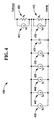
- FIG. 4 is an illustration of an equivalent electrical circuit model 400 showing the dominant sources of noise and other currents in a photodiode.
- R s is the series resistance 405 for the photodiode and is approximately 200 ohms in a standard photodiode.
- the thermal noise from the series resistance is modeled as current source I RS 410 and is approximately 9.1 pico-amps.
- R p is the shunt resistance 415 and is 500 mega-ohms.
- the thermal noise from the shunt resistance R p is modeled as current source I RP 420 and is approximately 0.006 pico-amps.
- the junction capacitance C J 425 is approximately 11 pico-farads and is responsible for the transmission of the thermal noise from the series resistance.
- I SD 430 is the shot noise from the dark current in the photodiode and is approximately 0.03 pico-amps.
- I SP is the shot noise from the photocurrent in the photodiode and is approximately 0.04 pico-amps. Defects in the silicon substrate cause flicker noise, which is modeled as current source I FL 440 and is approximately 0.02 pico-amps.
- I RS current source
- I RP current source
- I SD the photocurrent in the photodiode
- I SP and I FL represent the dominant sources of noise in the photodiode.
- I RS is the predominate source of noise at 9.1 pico-amps, which is 91 times larger the other four sources of noise combined.
- I DK 445 is the current source that represents the dark current in the photodiode or the current that flows when no light is present at the p-n junction.
- the dark current may vary from pico-amps to a few nano-amps depending upon the p-n junction area and process used to build the photodiode. The dark current is treated as an offset that is subtracted from the output of the photodiode.
- I PH 450 is a current source that represents the photocurrent, which is proportional to the amount of light energy that is absorbed by the photodiode over a specific time period. When collecting the faint reflected laser light from a small bar code, the photocurrent is in the range of 10 - 150 nano-amps.
- the first is optical or fiber optics based communications. Fiber optic applications are known to use high power and high data rates. The photocurrents generated in these applications are in the range of 2 to 80 micro-amps (approximately 500 time larger that in bar code applications). The relatively high photocurrents easily over power the thermal noise from the series resistance of the photodiode making the value of the series resistance of little importance.
- the second group of applications is used to detect extremely faint light such as a star or a night vision system. These applications detect very low levels of light but have relatively long exposure durations (collection times).
- Some applications have a collection time of 1 second, which would be 2.8 million times longer than the 0.35 microseconds of collection time that can be experienced by a laser scanner reading a 5-mil wide bar.
- the long collection times allows the thermal noise from the series resistance to cancel itself out. Since the thermal noise is random, statistics and measurements show that the effects of the noise will cancel out, if the collection time is sufficiently long.
- a collection time of one millisecond is sufficient time for the thermal noise to cancel out.
- a number of custom photodiodes where specifically fabricated to have a reduced series resistance while having a low or lower junction capacitance.
- the active area of the photodiode also had to be maintained so that the photodiodes would have a sufficient light absorption area to capture the very weak reflected laser light.
- Measurements of the series resistance for the custom photodiodes ranged from 11 - 84 ohms and the junction capacitance went as low as 5.8 pico-farads. Further tests showed that an optimal SNR resulted when the series resistance was about 80 ohms and the junction capacitance was about 6.7 pico-farads.
Landscapes
- Photometry And Measurement Of Optical Pulse Characteristics (AREA)
- Optical Recording Or Reproduction (AREA)
- Facsimile Scanning Arrangements (AREA)
- Optical Head (AREA)
Applications Claiming Priority (1)
| Application Number | Priority Date | Filing Date | Title |
|---|---|---|---|
| US11/749,220 US20080283605A1 (en) | 2007-05-16 | 2007-05-16 | Device and system for a low noise photodiode in a barcode scanner |
Publications (2)
| Publication Number | Publication Date |
|---|---|
| EP1995782A2 true EP1995782A2 (de) | 2008-11-26 |
| EP1995782A3 EP1995782A3 (de) | 2011-10-12 |
Family
ID=39730800
Family Applications (1)
| Application Number | Title | Priority Date | Filing Date |
|---|---|---|---|
| EP08250977A Withdrawn EP1995782A3 (de) | 2007-05-16 | 2008-03-19 | Vorrichtung und System für eine rauscharme Photodiode in einem Strichcode-Scanner |
Country Status (2)
| Country | Link |
|---|---|
| US (1) | US20080283605A1 (de) |
| EP (1) | EP1995782A3 (de) |
Family Cites Families (11)
| Publication number | Priority date | Publication date | Assignee | Title |
|---|---|---|---|---|
| DE69637397T2 (de) * | 1995-05-31 | 2009-01-02 | Symbol Technologies, Inc. | Optischer Barcode Abtaster |
| US5750980A (en) * | 1995-06-07 | 1998-05-12 | Computer Identics, Inc. | High-speed, high-resolution optical scanner system |
| US6422467B2 (en) * | 1995-12-18 | 2002-07-23 | Metrologic Instruments, Inc. | Reading system a variable pass-band |
| US6307660B1 (en) * | 1997-01-28 | 2001-10-23 | Tellium, Inc. | Optical receiver particularly useful for a multi-wavelength receiver array |
| US5886374A (en) * | 1998-01-05 | 1999-03-23 | Motorola, Inc. | Optically sensitive device and method |
| US6262465B1 (en) * | 1998-09-25 | 2001-07-17 | Picometrix, Inc. | Highly-doped P-type contact for high-speed, front-side illuminated photodiode |
| DE69906923T2 (de) * | 1998-12-28 | 2004-02-26 | Sharp K.K. | Lichtempfänger mit integrierter Schaltung |
| JP4208172B2 (ja) * | 2000-10-31 | 2009-01-14 | シャープ株式会社 | フォトダイオードおよびそれを用いた回路内蔵受光素子 |
| US7256470B2 (en) * | 2005-03-16 | 2007-08-14 | Udt Sensors, Inc. | Photodiode with controlled current leakage |
| ATE499705T1 (de) * | 2004-04-05 | 2011-03-15 | Nec Corp | Fotodiode und herstellungsverfahren dafür |
| US7264167B2 (en) * | 2004-11-30 | 2007-09-04 | Ncr Corporation | Optical scanner having micro-electro-mechanical systems mirror array and associated method |
-
2007
- 2007-05-16 US US11/749,220 patent/US20080283605A1/en not_active Abandoned
-
2008
- 2008-03-19 EP EP08250977A patent/EP1995782A3/de not_active Withdrawn
Also Published As
| Publication number | Publication date |
|---|---|
| US20080283605A1 (en) | 2008-11-20 |
| EP1995782A3 (de) | 2011-10-12 |
Similar Documents
| Publication | Publication Date | Title |
|---|---|---|
| CN110888117B (zh) | 使用多个雪崩光电二极管元件检测光 | |
| US7534994B2 (en) | Laser scanning system employing laser mode switching using a binary mode switching signal | |
| US20200072752A1 (en) | System and methods for detecting lifetime using photon counting photodetectors | |
| JPH02144786A (ja) | 光出力と走査角を調節できる走査装置及び方法 | |
| CN101393051A (zh) | 光检测装置 | |
| US10651835B1 (en) | Light detection with logarithmic current-to-voltage converter | |
| Simeonov et al. | Influence of the photomultiplier tube spatial uniformity on lidar signals | |
| CN109073563A (zh) | 用于检测颗粒的方法和传感器系统 | |
| CN104126187A (zh) | 用于条形码信号中的噪声减少的系统和方法 | |
| EP1995782A2 (de) | Vorrichtung und System für eine rauscharme Photodiode in einem Strichcode-Scanner | |
| US20090295960A1 (en) | Photodiode, photodiode array and image pickup device | |
| Titus et al. | CMOS photodetectors | |
| CN108647541B (zh) | 一种条码扫描芯片以及扫描方法 | |
| US8167208B2 (en) | Arrangement for and method of controlling monitor photodiode leakage current in lasers in electro-optical readers | |
| CN118408634A (zh) | 一种光检测电路、无源芯片及rfid系统 | |
| US9016579B2 (en) | Apparatus for and method of electro-optically reading a target in the presence of ambient light | |
| Vilella et al. | Dynamic range extension of SiPM detectors with the time-gated operation | |
| US7428999B2 (en) | MEMS-based electro-optical reader and method with extended working range | |
| KR100424366B1 (ko) | 이산분포형 확산층을 갖는 포토 다이오드와 제조방법 및이를 이용한 회로기판 및 전자기기 | |
| CN219038180U (zh) | 一种光学探测器 | |
| JP2002022497A (ja) | 光学式エンコーダ | |
| JP3165255B2 (ja) | 測距センサ | |
| JPH0621485A (ja) | 半導体受光モジュール | |
| JP2015517150A (ja) | バーコードリーダ用の可変ゲイン増幅器 | |
| JP3194573B2 (ja) | ガラス線量計読取装置におけるガラス素子識別コード読取装置及びそれに使用される線量計ガラス素子 |
Legal Events
| Date | Code | Title | Description |
|---|---|---|---|
| PUAI | Public reference made under article 153(3) epc to a published international application that has entered the european phase |
Free format text: ORIGINAL CODE: 0009012 |
|
| AK | Designated contracting states |
Kind code of ref document: A2 Designated state(s): AT BE BG CH CY CZ DE DK EE ES FI FR GB GR HR HU IE IS IT LI LT LU LV MC MT NL NO PL PT RO SE SI SK TR |
|
| AX | Request for extension of the european patent |
Extension state: AL BA MK RS |
|
| RAP1 | Party data changed (applicant data changed or rights of an application transferred) |
Owner name: NCR CORPORATION |
|
| PUAL | Search report despatched |
Free format text: ORIGINAL CODE: 0009013 |
|
| AK | Designated contracting states |
Kind code of ref document: A3 Designated state(s): AT BE BG CH CY CZ DE DK EE ES FI FR GB GR HR HU IE IS IT LI LT LU LV MC MT NL NO PL PT RO SE SI SK TR |
|
| AX | Request for extension of the european patent |
Extension state: AL BA MK RS |
|
| RIC1 | Information provided on ipc code assigned before grant |
Ipc: H01L 31/105 20060101ALI20110908BHEP Ipc: G06K 7/10 20060101ALI20110908BHEP Ipc: H01L 27/144 20060101AFI20110908BHEP |
|
| 17P | Request for examination filed |
Effective date: 20120412 |
|
| AKX | Designation fees paid |
Designated state(s): DE FR GB |
|
| 17Q | First examination report despatched |
Effective date: 20120523 |
|
| STAA | Information on the status of an ep patent application or granted ep patent |
Free format text: STATUS: THE APPLICATION HAS BEEN WITHDRAWN |
|
| 18W | Application withdrawn |
Effective date: 20120720 |