EP1995754B1 - Commutateur d'installation électrique - Google Patents
Commutateur d'installation électrique Download PDFInfo
- Publication number
- EP1995754B1 EP1995754B1 EP08006838.0A EP08006838A EP1995754B1 EP 1995754 B1 EP1995754 B1 EP 1995754B1 EP 08006838 A EP08006838 A EP 08006838A EP 1995754 B1 EP1995754 B1 EP 1995754B1
- Authority
- EP
- European Patent Office
- Prior art keywords
- lever
- contact
- switching device
- service switching
- electrical service
- Prior art date
- Legal status (The legal status is an assumption and is not a legal conclusion. Google has not performed a legal analysis and makes no representation as to the accuracy of the status listed.)
- Active
Links
Images


Classifications
-
- H—ELECTRICITY
- H01—ELECTRIC ELEMENTS
- H01H—ELECTRIC SWITCHES; RELAYS; SELECTORS; EMERGENCY PROTECTIVE DEVICES
- H01H71/00—Details of the protective switches or relays covered by groups H01H73/00 - H01H83/00
- H01H71/10—Operating or release mechanisms
- H01H71/12—Automatic release mechanisms with or without manual release
- H01H71/40—Combined electrothermal and electromagnetic mechanisms
-
- H—ELECTRICITY
- H01—ELECTRIC ELEMENTS
- H01H—ELECTRIC SWITCHES; RELAYS; SELECTORS; EMERGENCY PROTECTIVE DEVICES
- H01H71/00—Details of the protective switches or relays covered by groups H01H73/00 - H01H83/00
- H01H71/10—Operating or release mechanisms
- H01H71/50—Manual reset mechanisms which may be also used for manual release
- H01H71/52—Manual reset mechanisms which may be also used for manual release actuated by lever
- H01H71/526—Manual reset mechanisms which may be also used for manual release actuated by lever the lever forming a toggle linkage with a second lever, the free end of which is directly and releasably engageable with a contact structure
Definitions
- the invention relates to an electrical service switching device, in particular a circuit breaker, according to the preamble of claim 1.
- a generic service switching device usually has a contact point formed by a fixed and a movable contact piece, wherein the movable contact piece is held on a pivotally mounted contact lever.
- a generic installation switching device comprises a magnetic release with magnet armature and a thermal release, as well as a releasable from the thermal and the magnetic release switch lock with a Verklinkungsstelle. This is formed by a release lever and a stationary rotatably mounted, a slot for guiding a bracket having latch lever.
- the magnet armature can act on the opening of the contact point bearing on the movable contact piece contact lever and the switch lock can hold the contact lever permanently in the open position.
- a generic installation switching device comprises a switch knob for manual operation of the switching mechanism, and an intermediate lever which is hinged at its one end to the contact lever and with its other end to the bracket, wherein the bracket is articulated with at least one leg on the switch knob.
- the contact lever is acted upon in generic service switching devices by the force of a contact pressure spring, which is passed to the contact lever, that they in the closed position, the movable contact piece against the presses fixed contact piece, and pushes in the off position, the movable contact piece of the fixed contact piece.
- the intermediate lever is the link between the rear derailleur and the contact lever.
- the contact lever In the closed position, the contact lever is held by the interlock lever blocked by the derailleur. A first, displaceable pivot point of the contact lever is blocked by the latched derailleur in a first position, so that the contact pressure spring about the first pivot point can press the contact lever against the fixed contact piece.
- the intermediate lever In the tripped or off position, the intermediate lever is released by the derailleur.
- the derailleur is unlatched and releases the first pivot point of the contact lever, so that the contact pressure spring can press the contact lever to a second, fixed pivot point in the open position, in which the movable contact piece is removed from the fixed contact piece.
- the switching mechanism In thermal or short-circuit current cut-off, the switching mechanism is unlatched by the thermal or the electromagnetic release through the intermediary of a release lever, so that it can go from the switched to the off state.
- the movable contact lever In the case of electromagnetic rapid release, the movable contact lever is additionally directly pushed away by the magnet armature in order to quickly open the contact point, because the switching off via the unlatched rear derailleur is slower because of the mechanical inertia of the components involved than would be permitted with the quick release.
- DE 10 2004 055 564 A1 shows an installation switching device with a rear derailleur, the items are successively used together with the contact lever in the housing.
- the rear derailleur with the contact lever is no longer used as a prefabricated module, but it grows up, so to speak, within the housing.
- the thermal release and the contact lever are, based on the magnetic release, on different sides, so that an extension slide between the thermal release and the rear derailleur must be used separately as an extension of the rear derailleur.
- This construction should be suitable for fully automatic production, but it requires a high-precision supply and positioning of a large number of individual parts, which makes the production machine very complicated and expensive.
- the contact lever forms a first prefabricated insertable into the housing of the service switching device, which is pivotally mounted after insertion into the housing at a rotationally fixedly connected to the housing axis of rotation, and the switch knob forms with the release lever, the latch lever, the intermediate lever and the bracket a second prefabricated insertable into the housing assembly after insertion at a separation point with the first assembly articulated is connected.
- the second module is also referred to below as the articulated chain.
- the separation point is formed by a coupling point between a free end of the intermediate lever with a free end of the contact lever.
- the coupling point can be formed, for example, by an integrally formed on a free end of the contact lever bolt, which engages in a mounted at a free end of the intermediate lever recess.
- the two assemblies can be manufactured independently and pre-tested. By separating the "contact closure lever" functionality into two assemblies, each assembly is in itself less complex than an assembly that would incorporate all the functionality into a single assembly. As a result, each of the two assemblies according to the invention is easier and more reliable to manufacture.
- the assembly takes place in the housing at the separation point. During assembly, only two assemblies need to be inserted into the housing to maintain functionality. This can be done either simply by hand or by means of a production machine. The requirements on the production machines are manageable, since only two modules must be handled and positioned, and not a large number of individual parts.
- the movement path of the contact lever in the open position is limited by abutment against a fixedly connected to the housing stop.
- the stop absorbs the impact of the contact lever.
- an installation switching device comprises a percussion lever pivotally mounted in a stationary axis, via which both the armature and the thermal release act on the release lever.
- the hammer thus provides the coupling between the thermal or the magnetic release and the switch lock with the Verklinkungsstelle.
- the thermal and magnetic triggers can therefore be formed as separate assemblies and used independently and after insertion of the contact lever and the link chain in the housing.
- the hammer may be a double-arm lever, wherein in a very advantageous further embodiment, the armature and the thermal release act on a first arm of the hammer and pivot it on impact, so that the second arm of the hammer on an arm the release lever acts and this pivoted so that the Verklinkungsstelle between the release lever and the latch lever is unlatched.
- the contacts are very thick and thus designed oversized, or the sinking of the contact lever is limited by the length of the elongated hole in which the contact lever is mounted on the second, fixed axis of rotation.
- the latched state namely, when the contact lever is pressed by the first pivot point against the fixed contact piece, is the second, fixed axis of rotation in the interior of the slot.
- the smaller the thickness of the contact pieces the further the end of the elongated hole approaches the second, stationary axis of rotation.
- the second, stationary axis of rotation finally abuts against the edge of the elongated hole, a further pressing of the contact lever to the fixed contact piece is no longer possible, and the sinking is stopped.
- the sinking of the contact lever towards the fixed contact piece is limited by a fixed stop.
- a fixed stop This can be formed by a housing projection in a very advantageous embodiment of the invention. It can also be realized by a separate, but with the housing stationary and positive or even cohesively connected attachment.
- the advantage of the invention limiting the Nachsinkens by a stationary stop is that no contact pressure is lost and an improved reproducibility of the limiting threshold from device to device can be achieved.
- the function of the limitation of the Nachsinkens is inventively taken away from the slot and a separate component, the stop assigned. This can be optimized in its position and embodiment towards its only function, so that a total of an inventive installation switching device has improved properties.
- the position of the stop in the device corresponds to the path of movement of the release lever that the contact lever does not hinder pivoting of the release lever when abutting against the stop.
- An installation switching device here a circuit breaker, which is designated in its entirety by the reference numeral 10, has a housing which is composed of two housing half-shells, of which only the first housing half-shell 11 is partially shown.
- This housing half shell 11 has like the supplementary, not shown, second housing half shell a front front wall 12 and two rear front walls, of which in the FIG. 1 only a rear front wall 13 can be seen, the front side walls, of which in the figure, only one front side wall 14th can be seen, are interconnected. Further belonging to the housing rear narrow side walls, and a mounting side and broad sides of the housing are in the illustration of FIG. 1 not to be seen.
- each housing half-shell has a width which corresponds to one-half the standard module width.
- the housing half shell has a corresponding dimension, which is selected so that it reaches the module width together with the lid.
- the switch knob 19 has an opening which can be regarded as a virtual axis of rotation of the switch knob.
- On the switching handle 18 diametrically opposite side are two fork-shaped projections 21,22, of which in the illustration of FIG. 1 only one projection 21 is visible. In the perspective view of FIG. 6d Both fork-shaped projections 21, 22 can be seen.
- the two projections 21, 23 leave between a one-sided open receiving space 23 free.
- Each of the two projections 21, 22 has at its end remote from the handle 18 an eye-shaped opening 24, 25.
- the longitudinal center axis of the handle 18 extends through the center of the eye-shaped openings 24, 25th
- the intermediate lever 33 has at its one end in two fork-shaped projections 34, 35 expiring U-profile, each of the two fork-shaped projections 34,35 each terminal has a detent opening 31,32.
- the bar web 30 engages in an oblong hole 36 of a latch lever 37 arranged below the intermediate lever 33 and partially in the U-profile recess between the two terminal projections 34, 35 of the intermediate lever 33 and through it.
- the U-shaped bracket 27 is guided with its hoop web 30 in the slot 36 of the ratchet lever 37, and at the same time the intermediate lever 33 is articulated with its latching openings 31 and 32 on the hoop web 30.
- the switch knob 19, the intermediate lever 33 and the latch lever 37 thus form a coupled together by the bracket 27 assembly.
- a pin 38, 39 are integrally formed on both sides, with which it is stationary and rotatably mounted in a two-shell housing in two housing halves or in a single-shell housing with cover in the housing shell and the lid.
- the longitudinal direction of the intermediate lever 33, the pawl lever 37 and the legs 26, 29 of the bracket 27 are parallel to the broad side of the device housing.
- a release lever 40 is rotatably mounted. This is designed approximately L-shaped, see Fig. 6 , Wherein its first arm 41 has at its free end a joint head with a loop-shaped opening 42, with which it is rotatably mounted on the stationary shaft 20. Its second arm 43 is formed approximately at right angles to the first arm 42. The first arm 41 has approximately in its center a latching surface 44.
- the first arm 41 of the release lever 40 carries a locking lug 45.
- the release lever 40 is inserted with its first arm 41 into the receiving space 23 between the two fork-shaped projections 21,22 of the control knob 19, so that the central axis its eye-shaped opening 42 coincides with the central axis of the opening of the switch knob 19.
- the opening of the shift lever is seated on a bead 120 surrounding the eye-shaped opening 42, on which it is rotatably held.
- the release lever 40 is pivotally supported on the axis 20, and the switch knob 19 is pivotally supported on the release lever 40.
- the detent 45 holds a spring 46 fixed.
- the release lever 40 is added by coupling the switch knob 19, the intermediate lever 33 and the pawl lever 37 formed on the bracket 27 assembly.
- the latch lever 37 carries at its one free end a nose 49 which forms the Verklinkungsstelle of the switch lock together with the locking surface 44 on the release lever 40 in the Verklinkungswolf of the release lever 40.
- the circuit breaker 10 is shown with latched rear derailleur.
- the release lever 40 is clockwise in the view after FIG. 3 pivoted on the pawl lever 37 out.
- the release lever 40, the switch knob 19, the intermediate lever 33 and the pawl lever 37 thus form a coherent, vorfertigbare unit, which is also referred to below as the articulated chain 50.
- the articulated chain 50 can be prefabricated and pre-tested as a separate unit.
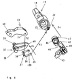
- FIG. 4 it is now the FIG. 4 considered, in which the individual steps in the assembly of the link chain 50 are shown in the form of an exploded view.
- the bracket 27 with a leg 29 through the slot 36 leads, so that the strap web 30 is slidably guided in the slot 36 and the pawl lever 37 between the two legs 26,29 of the Temple 27 runs.
- the intermediate lever 33 is clipped with its terminal locking openings 31 on the hoop web 30 so that its terminal projections 34, 35 cover the latch lever 37 and include.
- the bracket 27 is inserted with its terminal on the legs 26,29 integrally formed mecanical arrangementsn 28, 128 in the eye-shaped in openings 24,25 on the projections 21,22 of the switch knob 19.
- the release lever into which the spring arrangement 46 was previously inserted is inserted into the receiving space 23 between the fork-shaped projections 21, 22 of the switch knob 19 and locked therein.
- FIGS. 6a to 6d show more details of the spring assembly 46 and the assembly of the link chain 50.
- the spring assembly 46 is a coil spring which is pushed in the region of the condyle of the free end of the first arm 41 of the trigger lever 40 on the outer peripheral surface of the joint head.
- the condyle carries a roughly centered on its outer peripheral surface circumferential shoulder 51, which serves as a stop for the coil spring of the spring assembly 46. From the shoulder 51 extends toward the end face of the joint head indicative of a cup-shaped top surface 52, so that between the outer peripheral surface of the condyle and the top surface 52, a gap for receiving and guiding the spring assembly 46 is formed.
- the front side of the top surface 52 extends in the manner of a slope 53 from the stop edge of the paragraph 51 to the front side of the eye-shaped opening 42 and runs there in an undercut, so that a retaining pocket 54 is formed for the spring arm 47 of the spring assembly 46.
- FIG. 6a shows, is thus pushed onto the spring assembly 46 on the outer peripheral surface of the eye-shaped opening 42, so that the protruding spring arm 48 is held in a further undercut on the first arm 41 of the release lever 40.
- the second protruding spring arm 47 forms at a relaxed spring assembly 46 with the first protruding spring arm 48 is approximately a right angle.
- the second protruding spring arm 47 is pivoted along the slope 53 in a clockwise direction until it locks in the retaining pocket 54.
- the spring assembly 46 is now biased. As shown in FIG.
- the link chain 50 is assembled, its individual parts are hinged to each other, and the trigger lever 40 is biased in its Verklinkungsraum by the spring assembly 46.
- the intermediate lever 33 has at its end remote from the bracket 27 a recess 60. At this recess, it is connected by means of a cylindrical pin 61 hinged to the contact lever 62.
- the contact lever 62 is designed as a double-arm lever and rotatably mounted in a slot 66 on a fixedly connected to the first housing half-shell 11 axis 63, so that a first part lever 64 from the stationary axis 63 in the direction of the front front wall 12 points out, and a second Part lever 65 points from the stationary axis 63 in the direction of the attachment side of the housing. At the free end of the first partial lever 64 this carries the positively connected with him pin 61. The pin 61 thus forms the coupling point between the link chain 50 and the contact lever 62nd
- the first part lever 64 has a U-shaped contour with a receiving space 67 formed by the leg extending approximately parallel to the broad sides of the housing, which opens in the direction of the front side wall 14, and whose one leg has a recess, so that the receiving space 67 is accessible from the broad side of the removed housing half shell with the housing open.
- the second part lever 65 carries at its free end the movable contact piece 68th
- a contact pressure spring 69 which crashes with one end on the front side wall 14 of the housing, and with its second end in the receiving space 67 of the first partial lever 64, the contact lever 62 about the stationary axis 63 in a clockwise direction, so that the movable Contact piece 68 is pushed away from the fixed contact piece 70.
- the movement path of the contact lever 62 is limited by a fixedly connected to the first housing half-shell stop 71, in other words, in the off position of the contact lever 62 abuts against the stationary stop 71.
- the fixed stop 71 is formed by a bolt integrally connected to the housing half shell, which can be produced, for example, together with the housing half-shells in an injection molding process.
- FIG. 3 Here the circuit breaker is shown in the closed position.
- the switching handle 18 is in the closed position, the nose 49 on the pawl lever 37 is latched to the locking surface 44 on the trigger lever 40.
- the intermediate lever is blocked and the pin 61 at the coupling point between the link chain 50 and the contact lever 62 now forms the axis of rotation for the contact lever 62.Um this axis 61 presses the contact pressure spring 69, the contact lever 62 counterclockwise, and thus provides the contact between the movable contact piece 68 and the fixed contact piece 70 safely.
- the coil 72 of the magnetic release 73 and a strip 74 of bimetallic or a shape memory alloy as part of the thermal release 75.
- the contact lever 62 and the formed of the movable and the fixed contact piece 68,70 contact point between the magnetic release 73 and the thermal release 75.
- the magnetic release 73 and the thermal release 75 are relative to a through the contact lever 62 extending imaginary plane which is perpendicular to the first housing half shell 11, on different sides.
- the magnetic release 73 or the thermal release 75 When triggered, the magnetic release 73 or the thermal release 75 to open the latch 49 formed by the nose 49 on the pawl lever 37 and the locking surface 44 on the release lever, so that the switch lock is unlatched and the contact lever 62 by the contact pressure spring 69 in the in FIG. 1 Switching position shown can go over. For this it is necessary that the magnetic release and the thermal release are mechanically coupled to the release lever 40. In the embodiment of the present invention as shown in FIGS FIGS. 1 and 3 is shown, the mechanical coupling between the magnetic release 73 and the thermal release 75 with the release lever 40 via a stationary rotatably mounted hammer 77 occurs.
- axis 76 designed as a double arm lever whip lever 77 is pivotally mounted.
- a first partial arm 78 of the striking lever 77 points from the stationary axis 76 in the direction of the attachment side of the housing. It has an eye-shaped opening 79 in which a first leg of a transmission bracket 80 is movably held.
- the second leg of the transfer bracket 80 is guided displaceably in a guide groove 81 of the housing.
- the side walls 82 of the guide groove 81 are designed so deep, and the second leg of the transfer bracket 80 is accordingly Run so long that the strip 74 of the thermal release 75, when it bends when heated in the direction of arrow R, ie here counterclockwise, the side walls 82 of the guide groove 81 can run over and the transfer bracket 80 on the second leg in the direction of Drag arrow R along.
- the transfer bracket 80 pivots the hammer 77 in a clockwise direction, and this acts with its second arm 83 on the release lever 40, that it pivots counter to the force of the spring assembly 46 and counterclockwise, so that the locking surface 44 itself removed from the nose 49 and thus the Verklinkungsstelle is unlatched.
- the hammer 76 also has a nose 84 which projects in the direction of the second partial lever 65 of the contact lever 62. Now, if the striker pivots the hammer 77 in a clockwise direction in a magnetic release, then the nose 84 hits after the unlatching of Verklinkungsstelle on the contact lever 62 and proposes this in the in the FIG. 1 shown off position. In this case, the movable contact piece 68 is torn away from the fixed contact piece 70, wherein an arc is formed, which is deleted in a designated here in the figures by the reference numeral 85, only partially indicated arc quenching device.
- the arc quenching device comprises in a known manner an arc splitter stack with a pre-chamber space which may be bounded by Vorsch-cover plates parallel to the housing broad sides, and to which the arc is passed by means of two arc guide rails.
- the impact movement of the contact lever 62 is limited by the stationary stop 71.
- the advantage of the restriction by the stationary stop 71 is that the force transmitted from the striker to the contact lever 62, from the housing is received and not from parts of the switch latch.
- a second projection or a second nose 284 which points to the contact lever 62.
- the second nose 284 serves to limit the Verschwenkungsweges of the hammer 77 when it is pivoted in a thermal or magnetic release in a clockwise direction.
- a second stop 290 is stationary molded, see FIG. 1 ,
- the percussion lever 77 lies in its longitudinal direction approximately in an imaginary plane which is perpendicular to the housing half shell 11 and extends through the contact point formed from the movable and the fixed contact piece 68,70. In this way, a very compact and space-saving mutual arrangement of subassemblies switch lock, magnetic release, thermal release, contact lever with contact point can be realized.
- the switch lock, the contact lever 62 with the contact point, the thermal release 75 and the hammer 77, so almost all mechanically moving parts are arranged together in a first half-space of the housing, extending from an imaginary center plane perpendicular to the housing sides through the Center of the axis 20 of the switch knob 19 extends, extending to a narrow side of the housing.
- the arc quenching device 85 and the magnetic release 73 is housed in the other half space of the housing, which extends from the imaginary center plane to the opposite narrow side of the housing.
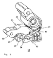
- FIG. 2 There, an assembly step is shown in which the contact lever 62 with the contact pressure spring 69 is already inserted into the housing, but not yet the link chain 50.
- the assembly is done in such a way that the contact lever 62 hinged with its slot 66 to the stationary axis 63 becomes.
- the contact pressure spring 69 is used. It is helpful that the first part lever 64 of the contact lever 62 has a recess on its one leg of the U-shaped contour. Thereby, the contact pressure spring 69 can be used in a simple way perpendicular to the housing broadside in the receiving space 67 of the first partial lever 64, in particular, this facilitates automatic assembly.
- the contact pressure spring 69 is supported on a wedge-shaped projection 86 on the front side wall 14, wherein the inclination of the support surface 87 relative to the front side wall 14 is selected so that they approximately parallel to the web of the first partial lever 64 in the on position of the contact lever 62 , on which the contact pressure spring 69 is supported on the contact lever side, and thus the contact pressure spring 69 in the closed position of the contact lever 62 extends substantially in a straight line between the front side wall 14 and the contact lever 62. This ensures good force transmission from the contact pressure spring 69 to the contact lever 62 and thus a high contact pressure force at the contact point.
- the contact lever is pressed by the contact pressure spring 69 with its second arm part 65 against the stop 71.
- the contact lever 62 is thus in a clearly defined and stable position. This is important because it facilitates the insertion of the link chain 50 following the next assembly step.
- the articulated chain 50 is now used so that it is articulated and pivotally mounted once on the stationary axis 20, and further with the recess 60 of the intermediate lever 33 on the pin 61 of the contact lever 62.
- the transfer bracket 80 is with its first leg in the opening 79 on the first arm 78 of the percussion lever 77 and with its second leg in the stationary with the housing connected guide groove 81 used.
- the service switching device according to the invention is thus constructed very easy to install.
- the articulated chain can be made of plastic parts, except for the spring assembly 46, which can be plugged together and clipped together in a simple manner. It eliminates the need to provide screw, solder, weld or rivet connections, as is still necessary in comparable devices according to the prior art.
- FIG. 7 a variant of a service switching device according to the invention is shown in a schematic representation, in which the sinking of the contact lever 162 toward the fixed contact piece 170 in the event that the thickness of the fixed and / or movable contact piece 168, 170 is greatly reduced by burning through a fixedly connected to the housing half shell 111 stop 90 is limited.
- the stopper 90 is formed as a housing projection, which protrudes into the interior of the housing at the corresponding location, and is produced in the manufacture of the housing halves by injection molding together with all other Gescouseanformungen in an injection molding process. It can also be realized by a separate, but with the housing stationary and positive or even cohesively connected attachment.
- Reference numerals 162, 168, 170 designate the contact lever, the movable contact piece and the fixed contact piece with the contact point closed and with no reduction in thickness due to erosion.
- the reference numerals 162a, 168a, 170a and in dashed lines designate the contact lever, the movable contact piece and the fixed contact piece with the contact point closed and with the reduction in thickness due to burnup. You can see that with heavy burnup the contact lever 162a is closer to the impact lever 177 when the contact point is closed than without burnup. By then existing greater distance of the contact lever 162a of the front side wall 114 of the housing, the contact pressure force of the contact pressure spring (in the FIG. 7 not shown).
- the position of the stopper 90 relative to the hammer 177 is chosen so that even with concern of the contact lever 162a on the stop 90 nor a sufficiently large strike distance 92 between the contact lever 162a and the nose 184 on the pivotally mounted in its stationary axis 176 hammer 177 is present.
- the impact distance 92 is so great that in the case of a thermal release, so if the transmission bracket pulls in the opening 179 on the hammer 177 in the direction of arrow P1, the hammer 177 can pivot in the clockwise direction in the direction of arrow P2 still far enough to act on the trigger lever 140 so that it can pivot counterclockwise in the direction of arrow P4, thereby opening the Verklinkungsstelle the switch latch.
- the hammer 177 could also be designed to be split along an imaginary plane parallel to the sides of the housing.
- This part carries the nose 184, and this acts in the case of magnetic release of the striker 173 of the magnetic release 73 in the direction of the arrow P5.
- the nose 184 can then rest directly on the contact lever 162a, without having to maintain a striking distance.
- For the mechanical coupling to the thermal release would take place via an outer part of the hammer, which has the required impact distance 92 and is mounted pivotably or displaceably relative to the inner part of the hammer.
- a further variant, which is not shown by figures, is that the hammer 177 only the movement of the striker 173 of the magnetic release 73 on the contact lever 162 and on the release lever 140 transmits, whereas the transmission of the movement of the thermal release via a transmission bracket directly takes place on the trigger, so without the interposition of the hammer, in otherwise compared to the FIGS. 1 to 3 unchanged arrangement of the link chain and the contact lever.
- the transfer bracket no longer acts as a drawbar, but as a pressure bar.
- the thermal release is designed in this variant so that it bends in the direction of the contact point when heated. In the in the FIGS. 1 to 3 In the embodiment shown, the strip 74 of the thermal release 75 bends in the direction away from the contact point when heated.
- FIG. 8 Yet another variant of the mechanical coupling of the thermal and the magnetic release 75, 73 to the release lever shows the FIG. 8 , There, the impact of the contact point is carried out directly by the striker 373 of the trigger 273 without detour via the hammer 277. The unlatching of the Verklinkungsstelle on the trigger lever 240 but takes place here with the interposition of the hammer 277. This provides a very quick and direct opening of the contact point in the event of a short circuit.
- the hammer 277 has an opening 285 through which the striker 373 of the magnetic release 273 extends through.
- a circumferential collar 374 is integrally formed in the region between the end face of the magnetic release 273 and the hammer 277.
- the striker 373 then moves along with the hammer 277, until it hits the contact lever 262 and beats it in the direction of arrow P3 in the clockwise direction in the open position.
Landscapes
- Physics & Mathematics (AREA)
- Electromagnetism (AREA)
- Breakers (AREA)
Claims (22)
- Commutateur d'installation électrique (10) comprenant un déclencheur magnétique (73) avec une armature d'aimant, un déclencheur thermique (75), un élément de contact fixe et un élément de contact mobile (70, 68), un verrou de maintien pouvant être déclenché par le déclencheur thermique et le déclencheur magnétique, avec un point d'encliquetage formé par un levier de déclenchement (40) et un levier à cliquet (37) monté à rotation et fixé en position, présentant un trou oblong (36) pour le guidage d'un étrier (27), l'armature d'aimant pouvant agir sur le levier de contact (62) portant l'élément de contact mobile (68) en cas de court-circuit pour ouvrir le point de contact et le verrou de maintien pouvant maintenir le levier de contact (62) dans la position ouverte, avec une manette de commutation (19) pour l'actionnement manuel du verrou de maintien et avec un levier intermédiaire (33), qui est articulé au niveau de l'une de ses extrémités au levier de contact (62) et au niveau de son autre extrémité à l'étrier (27), l'étrier (27) étant articulé par au moins une branche (29) à la manette de commutation (19), caractérisé en ce que le levier de contact (62) forme un premier module pouvant être inséré sous forme préfabriquée dans le boîtier du commutateur d'installation, lequel module est monté de manière à pouvoir pivoter après son insertion dans le boîtier au niveau d'un axe de rotation (61) connecté fixement au boîtier, et en ce que la manette de commutation (19) forme avec le levier de déclenchement (40), le levier à cliquet (37), le levier intermédiaire (33) et l'étrier (27) un deuxième module pouvant être inséré sous forme préfabriquée dans le boîtier, lequel module est connecté de manière articulée au premier module après l'insertion au niveau d'un point de séparation.
- Commutateur d'installation électrique selon la revendication 1, dans lequel la voie de déplacement du levier de contact peut être limitée dans la position d'ouverture par l'application contre une butée connectée fixement au boîtier.
- Commutateur d'installation électrique selon la revendication 1 ou 2, dans lequel le point de séparation est formé par un point d'accouplement entre une extrémité libre du levier intermédiaire et une extrémité libre du levier de contact.
- Commutateur d'installation électrique selon la revendication 3, dans lequel l'étrier présente approximativement une forme en U, avec une âme de l'étrier reliant les deux branches du U, et avec des saillies de guidage façonnées aux extrémités libres des branches du U.
- Commutateur d'installation électrique selon la revendication 4, dans lequel l'âme de l'étrier est guidée dans le trou oblong du levier à cliquet.
- Commutateur d'installation électrique selon la revendication 5, dans lequel la manette de commutation présente deux saillies façonnées en forme de fourche en position diamétralement opposée à la poignée de commutation, lesquelles saillies libèrent entre elles un espace de réception ouvert d'un côté, l'une des saillies de guidage de l'étrier étant maintenue de manière à pouvoir pivoter dans chacune des deux saillies.
- Commutateur d'installation électrique selon la revendication 6, dans lequel le levier intermédiaire présente, au niveau de son extrémité opposée au point de séparation, un profilé en U se terminant par deux saillies disposées en forme de fourche, et dans lequel chacune des deux saillies disposées en forme de fourche présente des ouvertures d'encliquetage disposées aux extrémités.
- Commutateur d'installation électrique selon la revendication 7, dans lequel le levier intermédiaire est articulé aux ouvertures d'encliquetage au niveau de l'âme de l'étrier et vient en prise avec ses saillies en forme de fourche autour du levier à cliquet.
- Commutateur d'installation électrique selon la revendication 8, dans lequel un premier bras du levier de déclenchement est encliqueté dans l'axe de rotation de la manette de commutation de manière articulée à celle-ci, et est entouré par les deux saillies en forme de fourche de la manette de commutation.
- Commutateur d'installation électrique selon la revendication 9, dans lequel une saillie réalisée sous forme de tourillon est à chaque fois façonnée de chaque côté du levier à cliquet, ces saillies lui permettant d'être monté dans les deux demi-coques du boîtier.
- Commutateur d'installation électrique selon la revendication 1, comprenant un levier de percussion monté de manière pivotante dans un axe fixe, par le biais duquel l'armature d'aimant et le déclencheur thermique agissent tous deux sur le levier de déclenchement.
- Commutateur d'installation électrique selon la revendication 11, dans lequel le levier de percussion est un levier à deux bras.
- Commutateur d'installation électrique selon la revendication 12, dans lequel l'armature d'aimant et le déclencheur thermique agissent sur un premier bras du levier de percussion et le font pivoter lors de son actionnement, de telle sorte que le deuxième bras du levier de percussion agisse sur un bras du levier de déclenchement et le fasse pivoter, de telle sorte que le point d'encliquetage entre le levier de déclenchement et le levier à cliquet soit désencliqueté.
- Commutateur d'installation électrique selon la revendication 11, dans lequel le levier de percussion (77, 177) est réalisé de manière divisée le long d'un plan imaginaire parallèlement aux côtés larges du boîtier, de telle sorte que le déclencheur magnétique (73), dans le cas d'un déclenchement magnétique, agisse sur une première partie interne du levier de percussion (177) et que le déclencheur thermique, dans le cas d'un déclenchement thermique, agisse sur une deuxième partie externe du levier de percussion (177).
- Commutateur d'installation électrique selon la revendication 11, dans lequel la voie de pivotement du levier de percussion (77, 177) peut être limitée par une deuxième butée fixe (290).
- Commutateur d'installation électrique selon la revendication 13, dans lequel le déclencheur thermique est connecté au levier de percussion au moyen d'un étrier de traction, et dans lequel, dans la position de fermeture du levier de contact, un deuxième bras du levier de déclenchement s'étend approximativement parallèlement à l'étrier de traction et le levier de percussion adopte une position approximativement à angle droit respectivement avec l'étrier de traction et avec le deuxième bras du levier de déclenchement.
- Commutateur d'installation électrique selon la revendication 16, dans lequel l'armature d'aimant frappe le levier de percussion en contact contre le levier de contact pour solliciter rapidement le point de contact.
- Commutateur d'installation électrique selon la revendication 16, dans lequel l'armature d'aimant, lors du déclenchement, fait d'abord pivoter le levier de percussion contre le levier de déclenchement puis le frappe ensuite en contact contre le levier de contact pour ouvrir le point de contact.
- Commutateur d'installation électrique selon la revendication 12, dans lequel l'armature d'aimant agit sur un premier bras du levier de percussion et fait pivoter celui-ci lors de l'actionnement, de telle sorte que le deuxième bras du levier de percussion agisse sur un bras du levier de déclenchement et le fasse pivoter de telle sorte que le point d'encliquetage entre le levier de déclenchement et le levier à cliquet soit désencliqueté, et dans lequel le déclencheur thermique agit directement par le biais d'un étrier de pression sur le levier de déclenchement pour le désencliquetage du point d'encliquetage, ou par le biais d'un étrier de pression sur le deuxième bras du levier de percussion en vue de le faire pivoter.
- Commutateur d'installation électrique selon la revendication 1, dans lequel un affaissement du levier de contact vers l'élément de contact fixe se produisant en cas d'usure de l'élément de contact mobile est limité par une butée fixe.
- Commutateur d'installation électrique selon la revendication 18, dans lequel la butée fixe est formée par une saillie du boîtier.
- Commutateur d'installation électrique selon la revendication 19, dans lequel le levier de contact, dans le cas d'un affaissement, est maintenu par la butée fixe dans une position telle que le pivotement du levier de déclenchement ne soit pas gêné dans le cas d'un déclenchement par le levier de contact.
Applications Claiming Priority (2)
| Application Number | Priority Date | Filing Date | Title |
|---|---|---|---|
| DE102007024268 | 2007-05-23 | ||
| DE102008006863A DE102008006863A1 (de) | 2007-05-23 | 2008-01-31 | Elektrisches Installationsschaltgerät |
Publications (2)
| Publication Number | Publication Date |
|---|---|
| EP1995754A1 EP1995754A1 (fr) | 2008-11-26 |
| EP1995754B1 true EP1995754B1 (fr) | 2013-09-04 |
Family
ID=39712625
Family Applications (1)
| Application Number | Title | Priority Date | Filing Date |
|---|---|---|---|
| EP08006838.0A Active EP1995754B1 (fr) | 2007-05-23 | 2008-04-04 | Commutateur d'installation électrique |
Country Status (3)
| Country | Link |
|---|---|
| US (1) | US7839241B2 (fr) |
| EP (1) | EP1995754B1 (fr) |
| CA (1) | CA2631921C (fr) |
Families Citing this family (13)
| Publication number | Priority date | Publication date | Assignee | Title |
|---|---|---|---|---|
| DE102006051807B8 (de) * | 2006-11-03 | 2008-06-26 | Abb Ag | Elektrischer Schalter |
| SI23333B (sl) * | 2010-03-08 | 2014-12-31 | Eti Elektroelement D.D. | Varnostno električno stikalo |
| CN102237208A (zh) * | 2010-05-03 | 2011-11-09 | Abb股份公司 | 电气安装开关设备 |
| DE102010032828B4 (de) * | 2010-07-30 | 2021-12-02 | Siemens Aktiengesellschaft | Schaltgerät, insbesondere Schutzschalter mit Kipphebel |
| JP5773762B2 (ja) * | 2011-06-03 | 2015-09-02 | キヤノン株式会社 | 電子機器 |
| EP2608233A1 (fr) * | 2011-12-23 | 2013-06-26 | Abb Ag | Commutateur de séparation de charge électrique pour basses tensions |
| DE202012001641U1 (de) * | 2011-12-23 | 2012-03-14 | Abb Ag | Elektrischer Lasttrennschalter für Niederspannung |
| US8809722B2 (en) * | 2012-10-11 | 2014-08-19 | Siemens Industry, Inc. | Circuit breaker with translating electrical contact, circuit breaker electrical contact assemblies, and operational methods |
| CN204118012U (zh) * | 2014-08-27 | 2015-01-21 | 浙江正泰电器股份有限公司 | 断路器的操作机构 |
| CN105575737B (zh) * | 2016-03-15 | 2017-10-20 | 佳一电气有限公司 | 一种断路器操作机构及断路器 |
| DE102016108292A1 (de) * | 2016-05-04 | 2017-11-09 | Abb Schweiz Ag | Elektrisches Installationsgerät mit Schaltstellungsanzeige |
| DE102016208930A1 (de) * | 2016-05-24 | 2017-11-30 | Siemens Aktiengesellschaft | Überlastauslöser |
| US10847333B2 (en) * | 2018-09-17 | 2020-11-24 | Siemends Industry, Inc. | Circuit breakers including dual triggering devices and methods of operating same |
Family Cites Families (17)
| Publication number | Priority date | Publication date | Assignee | Title |
|---|---|---|---|---|
| DE1638043A1 (de) * | 1968-03-08 | 1972-01-05 | Hundt & Weber | Ein Schaltschloss aufweisender Leistungsschalter |
| DE3021867A1 (de) * | 1980-06-11 | 1981-12-17 | Brown, Boveri & Cie Ag, 6800 Mannheim | Selbstschalter |
| DE3342469A1 (de) | 1983-11-24 | 1985-06-05 | Bbc Brown Boveri & Cie | Elektrischer schalter |
| USRE33400E (en) * | 1984-09-19 | 1990-10-23 | Mitsubishi Denki Kabushiki Kaisha | Circuit breaker |
| FR2581791B1 (fr) * | 1985-05-13 | 1988-11-04 | Merlin Gerin | Mecanisme de fermeture manuelle brusque d'un appareil de coupure de courant |
| FR2616583B1 (fr) * | 1987-06-09 | 1995-01-06 | Merlin Gerin | Mecanisme de commande d'un disjoncteur electrique miniature |
| JP2538991B2 (ja) * | 1988-06-09 | 1996-10-02 | 松下電工株式会社 | リモ―トコントロ―ル式回路しゃ断器 |
| EP0338930A1 (fr) * | 1988-04-22 | 1989-10-25 | Hager Electro S.A. | Disjoncteurs ou disjoncteurs differentiels |
| US4968863A (en) * | 1989-06-29 | 1990-11-06 | Square D Company | Unitary breaker assembly for a circuit breaker |
| US5162765A (en) * | 1991-12-23 | 1992-11-10 | North American Philips Corporation | Adjustable magnetic tripping device and circuit breaker including such device |
| IT1292339B1 (it) * | 1997-05-20 | 1999-01-29 | Gewiss Spa | Cinematismo di azionamento del contatto mobile particolarmente per interruttori elettrici automatici |
| FR2789220B1 (fr) * | 1999-02-01 | 2001-04-20 | Entrelec Sa | Mecanisme de commande d'un disjoncteur electrique |
| PT1170769E (pt) * | 2000-10-19 | 2002-07-31 | Hager Electro | Mecanismo de fecho rapido para aparelho electrico modular do tipo disjuntor |
| US6853274B2 (en) * | 2001-06-20 | 2005-02-08 | Airpax Corporation, Llc | Circuit breaker |
| DE10133878B4 (de) * | 2001-07-12 | 2004-07-08 | Siemens Ag | Schaltgerät mit einem Schaltschloss |
| US6667680B1 (en) * | 2002-06-27 | 2003-12-23 | Eaton Corporation | Circuit breaker |
| DE102004055564B4 (de) | 2004-11-18 | 2022-05-05 | Abb Ag | Elektrisches Installationsschaltgerät |
-
2008
- 2008-04-04 EP EP08006838.0A patent/EP1995754B1/fr active Active
- 2008-05-21 US US12/124,277 patent/US7839241B2/en active Active
- 2008-05-21 CA CA2631921A patent/CA2631921C/fr not_active Expired - Fee Related
Also Published As
| Publication number | Publication date |
|---|---|
| CA2631921A1 (fr) | 2008-11-23 |
| EP1995754A1 (fr) | 2008-11-26 |
| US7839241B2 (en) | 2010-11-23 |
| CA2631921C (fr) | 2015-02-17 |
| US20080290971A1 (en) | 2008-11-27 |
Similar Documents
| Publication | Publication Date | Title |
|---|---|---|
| EP1995754B1 (fr) | Commutateur d'installation électrique | |
| DE102008006863A1 (de) | Elektrisches Installationsschaltgerät | |
| EP2140521B1 (fr) | Commutateur d'installation comportant un dispositif de borne a ressort de rappel | |
| EP1760748B1 (fr) | Appareil de commutation électrique | |
| EP2137746B1 (fr) | Dispositif de verrouillage pour un appareil de coupure d'installation | |
| EP1812944A1 (fr) | Dispositif de commutation electrique d'une installation | |
| DE102011008833B4 (de) | Überstromauslöser und Installationsschaltgerät mit Überstromauslöser | |
| DE10216439B4 (de) | Hilfsschalter | |
| EP0091040B1 (fr) | Disjoncteur de protection à courant excessif | |
| EP1894218B1 (fr) | Appareil de commutation, disjoncteur de ligne et analogue | |
| DE102011008829B4 (de) | Installationsschaltgerät | |
| EP2087500B1 (fr) | Appareil de commutation d'installation à double coupure | |
| EP2608242A1 (fr) | Commutateur de séparation de charge électrique pour basses tensions | |
| EP2608233A1 (fr) | Commutateur de séparation de charge électrique pour basses tensions | |
| EP3945639A1 (fr) | Borne de raccordement de conducteur | |
| DE102012001336B4 (de) | Elektrischer Lasttrennschalter für Niederspannung | |
| DE602004003949T2 (de) | Dreheingriffs-verriegelungsmechanismus für automatische sicherheitsabtrennung | |
| DE102009051929B4 (de) | Elektrisches Installationsschaltgerät mit einem Schlaghebel | |
| DE102011008834A1 (de) | Installationsschaltgerät | |
| DE19507605C1 (de) | Verklinkungseinrichtung für elektrische Schalter | |
| EP1659604B1 (fr) | Appareil de commutation pour une installation électrique | |
| WO2000067275A1 (fr) | Unite coupe-circuit pour declenchement multipolaire | |
| EP0371419A2 (fr) | Disjoncteur électrique | |
| DE3425996C2 (fr) | ||
| EP2688085B1 (fr) | Commutateur d'installation électrique |
Legal Events
| Date | Code | Title | Description |
|---|---|---|---|
| PUAI | Public reference made under article 153(3) epc to a published international application that has entered the european phase |
Free format text: ORIGINAL CODE: 0009012 |
|
| AK | Designated contracting states |
Kind code of ref document: A1 Designated state(s): AT BE BG CH CY CZ DE DK EE ES FI FR GB GR HR HU IE IS IT LI LT LU LV MC MT NL NO PL PT RO SE SI SK TR |
|
| AX | Request for extension of the european patent |
Extension state: AL BA MK RS |
|
| 17P | Request for examination filed |
Effective date: 20081103 |
|
| AKX | Designation fees paid |
Designated state(s): AT BE BG CH CY CZ DE DK EE ES FI FR GB GR HR HU IE IS IT LI LT LU LV MC MT NL NO PL PT RO SE SI SK TR |
|
| GRAP | Despatch of communication of intention to grant a patent |
Free format text: ORIGINAL CODE: EPIDOSNIGR1 |
|
| INTG | Intention to grant announced |
Effective date: 20130531 |
|
| GRAS | Grant fee paid |
Free format text: ORIGINAL CODE: EPIDOSNIGR3 |
|
| GRAA | (expected) grant |
Free format text: ORIGINAL CODE: 0009210 |
|
| AK | Designated contracting states |
Kind code of ref document: B1 Designated state(s): AT BE BG CH CY CZ DE DK EE ES FI FR GB GR HR HU IE IS IT LI LT LU LV MC MT NL NO PL PT RO SE SI SK TR |
|
| REG | Reference to a national code |
Ref country code: GB Ref legal event code: FG4D Free format text: NOT ENGLISH |
|
| REG | Reference to a national code |
Ref country code: CH Ref legal event code: EP |
|
| REG | Reference to a national code |
Ref country code: AT Ref legal event code: REF Ref document number: 630900 Country of ref document: AT Kind code of ref document: T Effective date: 20130915 |
|
| REG | Reference to a national code |
Ref country code: IE Ref legal event code: FG4D Free format text: LANGUAGE OF EP DOCUMENT: GERMAN |
|
| REG | Reference to a national code |
Ref country code: DE Ref legal event code: R096 Ref document number: 502008010586 Country of ref document: DE Effective date: 20131031 |
|
| REG | Reference to a national code |
Ref country code: NL Ref legal event code: VDEP Effective date: 20130904 |
|
| PG25 | Lapsed in a contracting state [announced via postgrant information from national office to epo] |
Ref country code: NO Free format text: LAPSE BECAUSE OF FAILURE TO SUBMIT A TRANSLATION OF THE DESCRIPTION OR TO PAY THE FEE WITHIN THE PRESCRIBED TIME-LIMIT Effective date: 20131204 Ref country code: SE Free format text: LAPSE BECAUSE OF FAILURE TO SUBMIT A TRANSLATION OF THE DESCRIPTION OR TO PAY THE FEE WITHIN THE PRESCRIBED TIME-LIMIT Effective date: 20130904 Ref country code: CY Free format text: LAPSE BECAUSE OF FAILURE TO SUBMIT A TRANSLATION OF THE DESCRIPTION OR TO PAY THE FEE WITHIN THE PRESCRIBED TIME-LIMIT Effective date: 20130619 Ref country code: HR Free format text: LAPSE BECAUSE OF FAILURE TO SUBMIT A TRANSLATION OF THE DESCRIPTION OR TO PAY THE FEE WITHIN THE PRESCRIBED TIME-LIMIT Effective date: 20130904 Ref country code: LT Free format text: LAPSE BECAUSE OF FAILURE TO SUBMIT A TRANSLATION OF THE DESCRIPTION OR TO PAY THE FEE WITHIN THE PRESCRIBED TIME-LIMIT Effective date: 20130904 |
|
| REG | Reference to a national code |
Ref country code: NL Ref legal event code: VDEP Effective date: 20130904 |
|
| REG | Reference to a national code |
Ref country code: LT Ref legal event code: MG4D |
|
| PG25 | Lapsed in a contracting state [announced via postgrant information from national office to epo] |
Ref country code: GR Free format text: LAPSE BECAUSE OF FAILURE TO SUBMIT A TRANSLATION OF THE DESCRIPTION OR TO PAY THE FEE WITHIN THE PRESCRIBED TIME-LIMIT Effective date: 20131205 Ref country code: LV Free format text: LAPSE BECAUSE OF FAILURE TO SUBMIT A TRANSLATION OF THE DESCRIPTION OR TO PAY THE FEE WITHIN THE PRESCRIBED TIME-LIMIT Effective date: 20130904 Ref country code: SI Free format text: LAPSE BECAUSE OF FAILURE TO SUBMIT A TRANSLATION OF THE DESCRIPTION OR TO PAY THE FEE WITHIN THE PRESCRIBED TIME-LIMIT Effective date: 20130904 Ref country code: PL Free format text: LAPSE BECAUSE OF FAILURE TO SUBMIT A TRANSLATION OF THE DESCRIPTION OR TO PAY THE FEE WITHIN THE PRESCRIBED TIME-LIMIT Effective date: 20130904 Ref country code: FI Free format text: LAPSE BECAUSE OF FAILURE TO SUBMIT A TRANSLATION OF THE DESCRIPTION OR TO PAY THE FEE WITHIN THE PRESCRIBED TIME-LIMIT Effective date: 20130904 |
|
| PG25 | Lapsed in a contracting state [announced via postgrant information from national office to epo] |
Ref country code: CY Free format text: LAPSE BECAUSE OF FAILURE TO SUBMIT A TRANSLATION OF THE DESCRIPTION OR TO PAY THE FEE WITHIN THE PRESCRIBED TIME-LIMIT Effective date: 20130904 |
|
| PG25 | Lapsed in a contracting state [announced via postgrant information from national office to epo] |
Ref country code: IS Free format text: LAPSE BECAUSE OF FAILURE TO SUBMIT A TRANSLATION OF THE DESCRIPTION OR TO PAY THE FEE WITHIN THE PRESCRIBED TIME-LIMIT Effective date: 20140104 Ref country code: EE Free format text: LAPSE BECAUSE OF FAILURE TO SUBMIT A TRANSLATION OF THE DESCRIPTION OR TO PAY THE FEE WITHIN THE PRESCRIBED TIME-LIMIT Effective date: 20130904 Ref country code: SK Free format text: LAPSE BECAUSE OF FAILURE TO SUBMIT A TRANSLATION OF THE DESCRIPTION OR TO PAY THE FEE WITHIN THE PRESCRIBED TIME-LIMIT Effective date: 20130904 Ref country code: NL Free format text: LAPSE BECAUSE OF FAILURE TO SUBMIT A TRANSLATION OF THE DESCRIPTION OR TO PAY THE FEE WITHIN THE PRESCRIBED TIME-LIMIT Effective date: 20130904 Ref country code: CZ Free format text: LAPSE BECAUSE OF FAILURE TO SUBMIT A TRANSLATION OF THE DESCRIPTION OR TO PAY THE FEE WITHIN THE PRESCRIBED TIME-LIMIT Effective date: 20130904 Ref country code: RO Free format text: LAPSE BECAUSE OF FAILURE TO SUBMIT A TRANSLATION OF THE DESCRIPTION OR TO PAY THE FEE WITHIN THE PRESCRIBED TIME-LIMIT Effective date: 20130904 |
|
| PG25 | Lapsed in a contracting state [announced via postgrant information from national office to epo] |
Ref country code: ES Free format text: LAPSE BECAUSE OF FAILURE TO SUBMIT A TRANSLATION OF THE DESCRIPTION OR TO PAY THE FEE WITHIN THE PRESCRIBED TIME-LIMIT Effective date: 20130904 |
|
| REG | Reference to a national code |
Ref country code: DE Ref legal event code: R097 Ref document number: 502008010586 Country of ref document: DE |
|
| PG25 | Lapsed in a contracting state [announced via postgrant information from national office to epo] |
Ref country code: PT Free format text: LAPSE BECAUSE OF FAILURE TO SUBMIT A TRANSLATION OF THE DESCRIPTION OR TO PAY THE FEE WITHIN THE PRESCRIBED TIME-LIMIT Effective date: 20140106 |
|
| PLBE | No opposition filed within time limit |
Free format text: ORIGINAL CODE: 0009261 |
|
| STAA | Information on the status of an ep patent application or granted ep patent |
Free format text: STATUS: NO OPPOSITION FILED WITHIN TIME LIMIT |
|
| 26N | No opposition filed |
Effective date: 20140605 |
|
| REG | Reference to a national code |
Ref country code: DE Ref legal event code: R097 Ref document number: 502008010586 Country of ref document: DE Effective date: 20140605 |
|
| PG25 | Lapsed in a contracting state [announced via postgrant information from national office to epo] |
Ref country code: DK Free format text: LAPSE BECAUSE OF FAILURE TO SUBMIT A TRANSLATION OF THE DESCRIPTION OR TO PAY THE FEE WITHIN THE PRESCRIBED TIME-LIMIT Effective date: 20130904 |
|
| PG25 | Lapsed in a contracting state [announced via postgrant information from national office to epo] |
Ref country code: MC Free format text: LAPSE BECAUSE OF FAILURE TO SUBMIT A TRANSLATION OF THE DESCRIPTION OR TO PAY THE FEE WITHIN THE PRESCRIBED TIME-LIMIT Effective date: 20130904 Ref country code: LU Free format text: LAPSE BECAUSE OF FAILURE TO SUBMIT A TRANSLATION OF THE DESCRIPTION OR TO PAY THE FEE WITHIN THE PRESCRIBED TIME-LIMIT Effective date: 20140404 |
|
| REG | Reference to a national code |
Ref country code: CH Ref legal event code: PL |
|
| GBPC | Gb: european patent ceased through non-payment of renewal fee |
Effective date: 20140404 |
|
| REG | Reference to a national code |
Ref country code: IE Ref legal event code: MM4A |
|
| PG25 | Lapsed in a contracting state [announced via postgrant information from national office to epo] |
Ref country code: CH Free format text: LAPSE BECAUSE OF NON-PAYMENT OF DUE FEES Effective date: 20140430 Ref country code: LI Free format text: LAPSE BECAUSE OF NON-PAYMENT OF DUE FEES Effective date: 20140430 Ref country code: GB Free format text: LAPSE BECAUSE OF NON-PAYMENT OF DUE FEES Effective date: 20140404 |
|
| PG25 | Lapsed in a contracting state [announced via postgrant information from national office to epo] |
Ref country code: IE Free format text: LAPSE BECAUSE OF NON-PAYMENT OF DUE FEES Effective date: 20140404 |
|
| REG | Reference to a national code |
Ref country code: AT Ref legal event code: MM01 Ref document number: 630900 Country of ref document: AT Kind code of ref document: T Effective date: 20140404 |
|
| PG25 | Lapsed in a contracting state [announced via postgrant information from national office to epo] |
Ref country code: AT Free format text: LAPSE BECAUSE OF NON-PAYMENT OF DUE FEES Effective date: 20140404 |
|
| PG25 | Lapsed in a contracting state [announced via postgrant information from national office to epo] |
Ref country code: MT Free format text: LAPSE BECAUSE OF FAILURE TO SUBMIT A TRANSLATION OF THE DESCRIPTION OR TO PAY THE FEE WITHIN THE PRESCRIBED TIME-LIMIT Effective date: 20130904 |
|
| REG | Reference to a national code |
Ref country code: FR Ref legal event code: PLFP Year of fee payment: 9 |
|
| PG25 | Lapsed in a contracting state [announced via postgrant information from national office to epo] |
Ref country code: BG Free format text: LAPSE BECAUSE OF FAILURE TO SUBMIT A TRANSLATION OF THE DESCRIPTION OR TO PAY THE FEE WITHIN THE PRESCRIBED TIME-LIMIT Effective date: 20130904 |
|
| PG25 | Lapsed in a contracting state [announced via postgrant information from national office to epo] |
Ref country code: HU Free format text: LAPSE BECAUSE OF FAILURE TO SUBMIT A TRANSLATION OF THE DESCRIPTION OR TO PAY THE FEE WITHIN THE PRESCRIBED TIME-LIMIT; INVALID AB INITIO Effective date: 20080404 Ref country code: TR Free format text: LAPSE BECAUSE OF FAILURE TO SUBMIT A TRANSLATION OF THE DESCRIPTION OR TO PAY THE FEE WITHIN THE PRESCRIBED TIME-LIMIT Effective date: 20130904 Ref country code: BE Free format text: LAPSE BECAUSE OF FAILURE TO SUBMIT A TRANSLATION OF THE DESCRIPTION OR TO PAY THE FEE WITHIN THE PRESCRIBED TIME-LIMIT Effective date: 20140430 |
|
| PGFP | Annual fee paid to national office [announced via postgrant information from national office to epo] |
Ref country code: FR Payment date: 20160421 Year of fee payment: 9 Ref country code: IT Payment date: 20160427 Year of fee payment: 9 |
|
| REG | Reference to a national code |
Ref country code: FR Ref legal event code: ST Effective date: 20171229 |
|
| PG25 | Lapsed in a contracting state [announced via postgrant information from national office to epo] |
Ref country code: FR Free format text: LAPSE BECAUSE OF NON-PAYMENT OF DUE FEES Effective date: 20170502 |
|
| PG25 | Lapsed in a contracting state [announced via postgrant information from national office to epo] |
Ref country code: IT Free format text: LAPSE BECAUSE OF NON-PAYMENT OF DUE FEES Effective date: 20170404 |
|
| PGFP | Annual fee paid to national office [announced via postgrant information from national office to epo] |
Ref country code: DE Payment date: 20230420 Year of fee payment: 16 |