EP1995589A2 - Flaw detector of wire-rope - Google Patents
Flaw detector of wire-rope Download PDFInfo
- Publication number
- EP1995589A2 EP1995589A2 EP08009385A EP08009385A EP1995589A2 EP 1995589 A2 EP1995589 A2 EP 1995589A2 EP 08009385 A EP08009385 A EP 08009385A EP 08009385 A EP08009385 A EP 08009385A EP 1995589 A2 EP1995589 A2 EP 1995589A2
- Authority
- EP
- European Patent Office
- Prior art keywords
- detection means
- magnetic detection
- wire
- rope
- magnetic
- Prior art date
- Legal status (The legal status is an assumption and is not a legal conclusion. Google has not performed a legal analysis and makes no representation as to the accuracy of the status listed.)
- Granted
Links
Images



Classifications
-
- G—PHYSICS
- G01—MEASURING; TESTING
- G01N—INVESTIGATING OR ANALYSING MATERIALS BY DETERMINING THEIR CHEMICAL OR PHYSICAL PROPERTIES
- G01N27/00—Investigating or analysing materials by the use of electric, electrochemical, or magnetic means
- G01N27/72—Investigating or analysing materials by the use of electric, electrochemical, or magnetic means by investigating magnetic variables
- G01N27/82—Investigating or analysing materials by the use of electric, electrochemical, or magnetic means by investigating magnetic variables for investigating the presence of flaws
- G01N27/83—Investigating or analysing materials by the use of electric, electrochemical, or magnetic means by investigating magnetic variables for investigating the presence of flaws by investigating stray magnetic fields
- G01N27/87—Investigating or analysing materials by the use of electric, electrochemical, or magnetic means by investigating magnetic variables for investigating the presence of flaws by investigating stray magnetic fields using probes
Definitions
- the present invention relates to a flaw detector of a wire-rope, capable of detecting a damage such as a breakage or the like of a strand in a wire-rope in a used condition without removal of the wire-rope from any of various facilities which utilize wire-ropes, in order to ensure a safety for the facility.
- Wire ropes which are used for an elevator, a lift, a cable car, a crane and the like have a risk of successive fracture of steel wires as constitutional elements of the wire-rope, due to its fatigue or abrasion, the degree of the fracture increasing with time due to aging effect. If the degree of the fracture exceeds a predetermined value, it is determined that the service life of the wire-rope has been expired, and accordingly, the wire-rope is replaced with new one. Thus, a periodical inspection has to be carried out so as to measure a degree of fracture of steel wires in order to evaluate whether the wire-rope is still used in safety or not.
- Patent Document 1 JP-A-7-198684 , page 7 and Fig. 1
- a portable flaw detector a wire-rope tester
- an electromagnetic flaw detection process for quantitatively measure a degree of fracture of a wire-rope, which is capable of facilitating a maintenance service for a wire-rope which is laid along the ceiling of a building at a higher level, as used for a crane or the like, or in particular for a wire-rope laid in a narrow inspection space within, for example, an elevator, wherein the wire-rope is magnetized in its longitudinal direction by using a set of permanent magnets, and probe coils for detecting a magnetic flux leaking from steel wires are arranged among the permanent magnets so as to inspect a breakage of the steel wire.
- Patent Document 2 JP-A-2002-5896 , page 8 and Fig. 2
- Patent Document 2 JP-A-2002-5896 , page 8 and Fig. 2
- the presence of a fracture of a steel wire is determined in view of the presence of a peak in an output waveform obtained by a magnetic detection means.
- the position of a fracture of a wire steel is located in the inward part of a wire-rope, the distance between the position of the fracture and the magnetic sensor is long, and according, an output from a magnetic sensor is low.
- it is required to incorporate several A/D converters in the magnetic detection means.
- calibration is required for the respective A/D converters.
- the present invention is directed to solve the above-mentioned conventional problems, and accordingly, an object of the present invention is to provide a flaw detector of a wire-rope, which can enhance the reliability of measurement even though a fracture is present in a deep part of the wire-rope.
- Another object of the present invention is to provide a flaw detector of a wire-rope, which can reduce calibration working so as to be easily handled.
- a flaw detector of a wire-rope in which a magnetic flux is introduced through a wire-rope composed of a plurality of inter-twisted steel wires in the longitudinal direction thereof so as to detect a leakage flux caused in a damaged part of the steel wires, incorporating a magnetizer for magnetizing the wire-rope in the longitudinal direction thereof, a plurality of magnetic detection means arranged in the circumferential direction of the wire-rope, for detecting the leakage magnetic flux, a storage in which several relationships among at least two of the group depths of the damaged parts, degrees of damage, sums of values detected by the plurality of magnetic detection means and difference values detected by the magnetic detection means, have been previously stored, wherein a depth and/or a degree of damage of the damaged part are obtained from the values detected by the magnetic detection means and the values stored in the storage.
- the depth and the degree of damage of the damaged part can be obtained through the relationships among the values detected by the plurality of magnetic detection means arranged in the circumferential direction of a wire-rope, and the depths and the degrees of damage of the damaged parts which haven been previously stored in the storage, thereby it is possible to enhance the reliability.
- Fig. 1 shows the configuration of a flaw detector of a wire-rope 1.
- a magnetizer 2 is arranged so as to magnetize a wire-rope 1 in the longitudinal direction of the latter.
- a plurality of magnetic detection means coil and magnetic sensors
- a first magnetic detection means 3 for detecting a magnetic flux laid along the entire periphery of the wire-rope 1
- a plurality of second magnetic detection means 4a to 4h and a plurality of third magnetic detection means 4a to 4h which are arranged in ring-like shapes and which are adjacent to one another along the entire periphery of the wire-rope 1.
- the second magnetic detection means 4a to 4h and the third magnetic detection means are shifted in their phases from each other by 90 deg., that is, the magnetic detection means 4i spans in its intermediate part between the magnetic detection means 4a and 4b, 4j between 4b and 4c, similarly, 4k to 4p between 4a to 4h, respectively.
- An output from the first magnetic detection means 3 is delivered to a total meter 5, and outputs from the second magnetic detection means 4a to 4h and the third magnetic detection means 4i to 4p are delivered to a difference meter 6.
- A/D conversion for input signals are carried out in the total meter 5 and the difference meter 6.
- Signals after the conversion are delivered into a second CPU 7 for calculating a ratio between signals from the difference meter 6 and the total meter 5, and delivers a signal exhibiting a depth of damage based upon values of depths of damage with respect to signal ratios, which are stored in a storage 8, to a display unit 11.
- a second CPU 9 calculates a degree of damage from a signal from the total meter 6, a signal from the difference meter 6, and data of threshold values stored in the storage for diagnosis.
- a difference between outputs from the magnetic detection means 4a, 4b is about 98 %.
- the deeper the damaged part in the wire-rope the smaller the difference in output between the magnetic detection means near the damaged part, and the magnetic detection means adjacent to the former means, that is, for example, the difference in output is 71 % if the distance from the damaged part to the center of the wire-rope is 4 mm, while the difference in output is 27 % if the distance from the damaged part to the center is 2 mm.
- the depth of the damaged part can be calculated by the first difference meter 6.
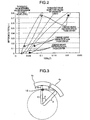
- Fig. 2 shows examples in the cases that, as to the relationship between a ratio of a difference value and a total value, and the total value, the damaged values (the number of damaged parts) are 1 and 2, and the distance from the damaged part to the center of the rope are 2 mm, 4 mm and 6 mm.
- the sum of the absolute value of a difference from the second detection means and the absolute of a difference value from the third detection means is used as the difference value.
- a threshold value is set at an intermediate position between the damaged value 1 and the damaged value 2, and it is diagnosed that the degree of damage is not less than 2 if the degree of damage exceeds the threshold value. Further, it is diagnosed that the degree of damage is 0 if the degree of damage is less than a noise level which has been previously obtained through experiments or the like.
- the storage 10 has been stored therein with threshold values and values of noise levels, as stated above, and the second CPU 9 delivers the damaged value to the display unit 11.
- the storages 8, 10 may be stored therein with, for example, relationships among depths of damage, total values and difference values, from which a depth of damage and a degree of damage may be obtained.
- the difference value becomes 0 at this time.
- the third detection means 4i to 4p the damaged part is located at the center of the magnetic detection means 4i.
- difference values are obtained from outputs from the magnetic detection means 4i to 4p.
- the third detection means are located, intermediate of the second detection means 4a to 4h in order to obtain difference values from the outputs from the third detection means even though the difference values of the output from the second detection means becomes 0.
- eight magnetic detection means are provided in total as the second magnetic means 4a to 4h and the third detection means 4i to 4p, respectively.
- the difference in output between a magnetic detection means 4y which delivers a peak value and a magnetic detection means 4x or 4z, which is adjacent thereto becomes about 98 %. Meanwhile, if the number of the magnetic detection means is 72, a difference in output between the magnetic detection means 4y which delivers a peak value, and the magnetic detection means 4x or 4z which is adjacent thereto becomes about 33 %.
- the difference in output between a magnetic detection means which delivers a peak output value, and a magnetic detection means which is adjacent thereto becomes largest while the difference in output between the other magnetic detection means becomes small, and accordingly, no diagnosis can be made if no difference in output between the magnetic detection means which delivers a peak output and the magnetic detection means which is adjacent to the former obtained can be obtained.
- the peak output is set to a value which is at least larger than two times as large as the output from the adjacent magnetic detection means.
- a total number of the magnetic detection means is calculated from the positional relationships between the damaged part and the magnetic detection means, as shown in Fig. 3 , and the relationship among magnitudes of magnetic fluxes.
- the number of the second magnetic detection means has to be set to at least two since a difference value should be obtained therefrom. If the damaged part 12 is located at the center of the magnetic detection means 4x, the damaged part 12 is longer from the magnetic distance 4y. In this case, the magnetic fluxes of the magnetic detection means 4x, 4y at their centers are different from each other, and accordingly, the difference value can be obtained, literally.
- the number of the respective first and second magnetic means is set to be preferably not less than two.
- the smaller the number of the magnetic detection means the wider the area in which a leakage magnetic flux caused by a damage should be detected by the magnetic detection means which detect a value of an averaged magnetic flux density, and a variation in the magnetic flux density within the area, and accordingly, if the magnetic flux caused by a damage is constant while the magnetic flux density become larger only in a specific zone in the detection area of the magnetic detection means, should the detection area of the magnetic detection means be larger, the sensitivity would be lower.
- the magnetic detection means delivers an output in the form of an averaged value over an area covered by the magnetic detection means. For example, if the number of the magnetic detection value is two, the area covered by the single magnetic detection means corresponds to an angel of 180 deg., while, the number of the magnetic detection means is 8, the area covered by the single magnetic detection means corresponds to an angle of 45 deg, the smaller the number of the magnetic means, the lower the sensitiveness.
- Fig. 5 shows the relationship between the number of the magnetic detection means and outputs of the magnetic detection mean.
- the calculated value inevitably includes noises caused by affection of concavities and convexities of strands, rattling during measurement and the like.
- the noises are allowable if it is 20 % of a peak value although it depends upon a measuring way.
- it is preferably to set the number of the magnetic detection means to not less than 4 but not greater than 20 in practice.
- the difference values in output from the second or third magnetic detection means are measured. Accordingly, the magnetic detection means are mounted with the directions of their sensitiveness being determined when the magnetic detection means are arranged.
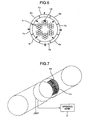
- Fig. 6 which shows an example of the arrangement of the magnetic detection means 4a to 4h, the magnetic detection means 4a, 4c, 4e and 4g are located so that they deliver positive outputs with respect to magnetic fluxes outward from the center of the wire-rope, and the remaining magnetic detection means are arranged so that they deliver negative outputs with respect to magnetic fluxes outward from the center of the wire-rope.
- the value of difference can be obtained from the sum of outputs from the respective magnetic means.
- Fig. 7 which shows the case that coils are used, the directions of winding of the coils are alternately reversed in order to set the directions of sensitiveness to be alternate, all coils being connected in series so as to obtain a difference value.
- the magnetic detection means may be those which can detect a circumferential magnetic flux distribution, and accordingly, for example, the sum of the outputs from a plurality of divided magnetic detection means may be used, being substituted for the outputs of the magnetic detection means.
- the intervals of the respective magnetic means should be set to be small in order to a peak of a leakage flux caused by damage can be surely measured.
- the first magnetic detection means, the second magnetic detection means 4a to 4h and the third magnetic detection means 4i to 4p are arranged being shifted from one another in the longitudinal direction of the wire-rope.
- This configuration can facilitate the mounting of the magnetic detection means onto the wire-rope since their respective wirings are not overlapped with one another.
- time compensators 14a to 14c are provided so that output values from the respective magnetic detection means exhibit measured data in the one and the same section of the wire-rope. That is, during measurements, when the wire-rope 1 is travelled, the outputs of the magnetic detection means are delayed by 2L/v where v is traveling speed (m/sec), and L is a distance (m) by which the magnetic detection means 3 and the magnetic detection mean 4a to 4h and 4i to 4p are shifted from one another, in the case that the wire-rope passes at first through the magnetic detection means 3, then passes by the magnetic detection means 4a to 4h, and finally passes by the magnetic detection means 4i to 4p, that is, the processing of the outputs of the magnetic detection means 4a to 4h are made by delaying their outputs by 2L/V.
- a storage 15 is stored therein with values of correction times with respect to speeds of the wire-ropes, and accordingly, the time compensators 14a to 14c carry out the time correction, being based upon these values, and the results thereof are delivered from the total meter 5 and the difference meter 6.
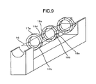
- Fig. 9 shows a third embodiment in which a wire-rope on use is fixed at its ends, the flaw detector is split into a plurality of sensor units so that the flaw detector can be easily inserted onto the wire-rope.
- the first magnetic detection means two halves, that is, magnetic detection means 17a and 17b are connected so that the sum of outputs therefrom is delivered.
- the magnetic detection means 4a to 4h and the magnetic detection means 4i to 4p some of them would be possibly located at the split plane 16, and accordingly, each of the some crossing the split plane 16 is split into two parts whose sensitivities are adjusted so that the sum of outputs from them is equal to the output of the magnetic detection means which has not yet been split.
- two magnetic detection means 18a and 18b are arranged interposing therebetween the split plane 16, instead of the magnetic detection means 4c, and the sensitivities thereof are set to a value which is one half of that of the magnetic detection means 4c.
- two magnetic detection means 18a and 18d are arranged, instead of the magnetic detection means 4g.
- coils are used as the magnetic detection means, their numbers of turns may be set to be equal to one another while their sectional areas are set to one-half of that of the original magnetic detection means. It is noted that the adjustment for the sensitivity may be always made not only by the adjustment to the sectional area but also by the adjustment to the number of turns, the adjustment to an electric gain made by an amplifier, or by the combination thereof.
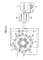
- Fig. 10 shows a fourth embodiment in which the second and third magnetic detection means are laid along the entire periphery of the wire-rope while the first magnetic detection means is omitted.
- the sum of outputs from the magnetic detection means 4a, 4c, 4e and 4g is measured by a sing total member 19a while the sum of outputs from the magnetic detection means 4b, 4d, 4f and 4h is measured by a single total meter 19b. Further, the sum of outputs from the total meter 19a and the total meter 19b corresponds to the total value measured by the first magnetic detection means, and the difference between the outputs from the total meter 19a and the total meter 19b corresponds to the difference value measured by the second magnetic detection means.
- the first magnetic detection means can be omitted, and further, the burden of the calibration for the respective magnetic detection means can be reduced.
Landscapes
- Chemical & Material Sciences (AREA)
- Chemical Kinetics & Catalysis (AREA)
- Electrochemistry (AREA)
- Physics & Mathematics (AREA)
- Health & Medical Sciences (AREA)
- Life Sciences & Earth Sciences (AREA)
- Analytical Chemistry (AREA)
- Biochemistry (AREA)
- General Health & Medical Sciences (AREA)
- General Physics & Mathematics (AREA)
- Immunology (AREA)
- Pathology (AREA)
- Investigating Or Analyzing Materials By The Use Of Magnetic Means (AREA)
- Measurement Of Length, Angles, Or The Like Using Electric Or Magnetic Means (AREA)
Abstract
Description
- The present invention relates to a flaw detector of a wire-rope, capable of detecting a damage such as a breakage or the like of a strand in a wire-rope in a used condition without removal of the wire-rope from any of various facilities which utilize wire-ropes, in order to ensure a safety for the facility.
- Wire ropes which are used for an elevator, a lift, a cable car, a crane and the like have a risk of successive fracture of steel wires as constitutional elements of the wire-rope, due to its fatigue or abrasion, the degree of the fracture increasing with time due to aging effect. If the degree of the fracture exceeds a predetermined value, it is determined that the service life of the wire-rope has been expired, and accordingly, the wire-rope is replaced with new one. Thus, a periodical inspection has to be carried out so as to measure a degree of fracture of steel wires in order to evaluate whether the wire-rope is still used in safety or not.
- Heretofore, visual inspection has been carried out for inspecting a degree of fracture of a wire-rope in use. Such a visual inspection has not been practical since a long working time is required for a long wire-rope.
- Thus, as disclosed in, for example, Patent Document 1 (
JP-A-7-198684 page 7 andFig. 1 ), there has been proposed a portable flaw detector (a wire-rope tester) utilizing an electromagnetic flaw detection process, for quantitatively measure a degree of fracture of a wire-rope, which is capable of facilitating a maintenance service for a wire-rope which is laid along the ceiling of a building at a higher level, as used for a crane or the like, or in particular for a wire-rope laid in a narrow inspection space within, for example, an elevator, wherein the wire-rope is magnetized in its longitudinal direction by using a set of permanent magnets, and probe coils for detecting a magnetic flux leaking from steel wires are arranged among the permanent magnets so as to inspect a breakage of the steel wire. - Further, there has been also known, as disclosed in, for example, Patent Document 2 (
JP-A-2002-5896 page 8 andFig. 2 ), there has been known such a method that those of leakage magnetic fluxes detected by magnetic sensors arranged in the circumferential direction of a wire-rope, which exceed a predetermined reference value are extracted as damages signals relating to the strands in order that damages such as breakages or local abrasions at several positions are precisely detected by using a leakage magnetic flux process, and then whether or not these damages have the degrees that require the replacement of wire-ropes is automatically determined. - Conventionally, steel wires in the outermost layer of the wire-rope, though which the wire-rope makes contact with sheaves or pulleys have been usually broken. However, these years, the wire-ropes are used for various purposes, and further, the structures of the wire-ropes have been complicated. Thus, the steel wires which are located in the inward part of the wire-rope would be possibly broken. In this case, the position where a fracture occurs within the wire-rope should be probed in order to examine the mechanism of a damage.
- In the above-mentioned conventional technology, the presence of a fracture of a steel wire is determined in view of the presence of a peak in an output waveform obtained by a magnetic detection means. However, if the position of a fracture of a wire steel is located in the inward part of a wire-rope, the distance between the position of the fracture and the magnetic sensor is long, and according, an output from a magnetic sensor is low. Thus, it is required to incorporate several A/D converters in the magnetic detection means. Thus, calibration is required for the respective A/D converters.
- The present invention is directed to solve the above-mentioned conventional problems, and accordingly, an object of the present invention is to provide a flaw detector of a wire-rope, which can enhance the reliability of measurement even though a fracture is present in a deep part of the wire-rope.
- Further, another object of the present invention is to provide a flaw detector of a wire-rope, which can reduce calibration working so as to be easily handled.
- To the end, according to the present invention, there is provided a flaw detector of a wire-rope, in which a magnetic flux is introduced through a wire-rope composed of a plurality of inter-twisted steel wires in the longitudinal direction thereof so as to detect a leakage flux caused in a damaged part of the steel wires, incorporating a magnetizer for magnetizing the wire-rope in the longitudinal direction thereof, a plurality of magnetic detection means arranged in the circumferential direction of the wire-rope, for detecting the leakage magnetic flux, a storage in which several relationships among at least two of the group depths of the damaged parts, degrees of damage, sums of values detected by the plurality of magnetic detection means and difference values detected by the magnetic detection means, have been previously stored, wherein a depth and/or a degree of damage of the damaged part are obtained from the values detected by the magnetic detection means and the values stored in the storage.
- According to the present invention, even though the position of a fracture of a steel wire is located in the inward part of the wire-rope, the depth and the degree of damage of the damaged part can be obtained through the relationships among the values detected by the plurality of magnetic detection means arranged in the circumferential direction of a wire-rope, and the depths and the degrees of damage of the damaged parts which haven been previously stored in the storage, thereby it is possible to enhance the reliability.
-
-
Fig. 1 is a perspective view illustrating a flaw detector of a wire-rope in an embodiment of the present invention; -
Fig. 2 is a graph exhibiting relationships among depth of damaged parts, degrees of damage, sums of values detected by a plurality of magnetic detection means, and difference values detected by adjacent magnetic detection means, in the embodiment of the present invention; -
Fig. 3 is a sectional view for explaining the positional relationship between the arrangement of the magnetic detection means, and a damaged part in the embodiment of the present invention; -
Fig. 4 is a graph exhibiting the relationship between the output value of the magnetic detection means and the angle which is made between the magnetic detection means and a single magnetic pole; -
Fig. 5 is a graph exhibiting the relationship between a number of magnetic detection means and a detection sensitiveness in the embodiment of the present invention; -
Fig. 6 is a sectional view for explaining positions where the plurality of magnetic detection means are located, in the embodiment of the present invention; -
Fig. 7 is a schematic perspective view illustrating the magnetic detection means in the embodiment of the present invention; -
Fig. 8 is a perspective view illustrating a flaw detector of a wire-rope in another embodiment of the present invention; -
Fig. 9 is a perspective view illustrating a flaw detector of a wire-rope in further another embodiment of the present invention; and -
Fig. 10 is a block diagram illustrating a flaw detector of a wire-rope in further another embodiment of the present invention. - Explanation will be hereinbelow made of preferable embodiments of the present invention with reference to the accompanying drawings:
-
Fig. 1 shows the configuration of a flaw detector of a wire-rope 1. - A
magnetizer 2 is arranged so as to magnetize a wire-rope 1 in the longitudinal direction of the latter. There are arranged around the wire-rope 1 a plurality of magnetic detection means (coils and magnetic sensors), that is, a first magnetic detection means 3 for detecting a magnetic flux, laid along the entire periphery of the wire-rope 1, a plurality of second magnetic detection means 4a to 4h and a plurality of third magnetic detection means 4a to 4h, which are arranged in ring-like shapes and which are adjacent to one another along the entire periphery of the wire-rope 1. - The second magnetic detection means 4a to 4h and the third magnetic detection means are shifted in their phases from each other by 90 deg., that is, the magnetic detection means 4i spans in its intermediate part between the magnetic detection means 4a and 4b, 4j between 4b and 4c, similarly, 4k to 4p between 4a to 4h, respectively. An output from the first magnetic detection means 3 is delivered to a
total meter 5, and outputs from the second magnetic detection means 4a to 4h and the third magnetic detection means 4i to 4p are delivered to adifference meter 6. A/D conversion for input signals are carried out in thetotal meter 5 and thedifference meter 6. - Signals after the conversion are delivered into a
second CPU 7 for calculating a ratio between signals from thedifference meter 6 and thetotal meter 5, and delivers a signal exhibiting a depth of damage based upon values of depths of damage with respect to signal ratios, which are stored in astorage 8, to adisplay unit 11. Asecond CPU 9 calculates a degree of damage from a signal from thetotal meter 6, a signal from thedifference meter 6, and data of threshold values stored in the storage for diagnosis. Next, explanation will be made of the diagnostic logics of thefirst CPU 7 and thesecond CPU 9 shown inFig. 1 . In the case that a damaged part is located at a position which is shallow in the wire-rope 1 as measured from the outer surface of the wire-rope 1, at the center of the magnetic detection means 4a, that is, the magnetic detection means is located on the circumference of a circle having a radius of 7 mm while the damaged part is located at a position having a distance of 6 mm from the center of the wire-rope 1, a difference between outputs from the magnetic detection means 4a, 4b is about 98 %. - Thus, the deeper the damaged part in the wire-rope, the smaller the difference in output between the magnetic detection means near the damaged part, and the magnetic detection means adjacent to the former means, that is, for example, the difference in output is 71 % if the distance from the damaged part to the center of the wire-rope is 4 mm, while the difference in output is 27 % if the distance from the damaged part to the center is 2 mm. The further the damaged part from the center or the shallower the damaged part, the larger the output ratio. Thus, storing the above-mentioned relationship in the
storage 8, the depth of the damaged part can be calculated by thefirst difference meter 6. -
Fig. 2 shows examples in the cases that, as to the relationship between a ratio of a difference value and a total value, and the total value, the damaged values (the number of damaged parts) are 1 and 2, and the distance from the damaged part to the center of the rope are 2 mm, 4 mm and 6 mm. In this case, the sum of the absolute value of a difference from the second detection means and the absolute of a difference value from the third detection means is used as the difference value. - With reference to
Fig. 2 , if the degrees of damage are equal to each other, date are plotted in a substantially straight-like manner. From this reason, a threshold value is set at an intermediate position between the damagedvalue 1 and the damagedvalue 2, and it is diagnosed that the degree of damage is not less than 2 if the degree of damage exceeds the threshold value. Further, it is diagnosed that the degree of damage is 0 if the degree of damage is less than a noise level which has been previously obtained through experiments or the like. Thestorage 10 has been stored therein with threshold values and values of noise levels, as stated above, and thesecond CPU 9 delivers the damaged value to thedisplay unit 11. - The
storages - Next, explanation will be made of differences between the outputs of the second magnetic detection means 4a to 4h and the third detection means 4i to 4p shown in
Fig. 1 . - If a damaged part is present between the magnetic detection means 4a and 4b, outputs from the magnetic detection means 4a, 4b are equal to each other. Accordingly, the difference value becomes 0 at this time. At this time, as to the third detection means 4i to 4p, the damaged part is located at the center of the magnetic detection means 4i. Thus, difference values are obtained from outputs from the magnetic detection means 4i to 4p. Thus, the third detection means are located, intermediate of the second detection means 4a to 4h in order to obtain difference values from the outputs from the third detection means even though the difference values of the output from the second detection means becomes 0.
- In the above-mentioned example, eight magnetic detection means are provided in total as the second magnetic means 4a to 4h and the third detection means 4i to 4p, respectively.
- In the case of eight magnetic detection means, the difference in output between a magnetic detection means 4y which delivers a peak value and a magnetic detection means 4x or 4z, which is adjacent thereto, becomes about 98 %. Meanwhile, if the number of the magnetic detection means is 72, a difference in output between the magnetic detection means 4y which delivers a peak value, and the magnetic detection means 4x or 4z which is adjacent thereto becomes about 33 %. As to the calculation of the difference values, the difference in output between a magnetic detection means which delivers a peak output value, and a magnetic detection means which is adjacent thereto becomes largest while the difference in output between the other magnetic detection means becomes small, and accordingly, no diagnosis can be made if no difference in output between the magnetic detection means which delivers a peak output and the magnetic detection means which is adjacent to the former obtained can be obtained.
- Further, as to the calculation for the difference value, since the outputs from the two magnetic means which are adjacent to the magnetic detection means which delivers the peak output is subtracted from the peak output, the peak output is set to a value which is at least larger than two times as large as the output from the adjacent magnetic detection means.
- Since the magnetic flux is inversely proportional to the square of a distance, a total number of the magnetic detection means is calculated from the positional relationships between the damaged part and the magnetic detection means, as shown in
Fig. 3 , and the relationship among magnitudes of magnetic fluxes. - As shown in
Fig. 3 , the distance h from the magnetic detection means 4y to the damagedpart 12 can be obtained by the theorem of cosine: h2 =R2 + d2 - 2Rdcosθ where R is a distance from the damaged part to the center of the wire-rope, d is a distance from the center of the wire-rope to the magnetic detection means, and θ is an included angle between the magnetic detection means 4x and 4y with respect to the center of the wire-rope. - Next, since the output of the magnetic detection means is inversely proportional to the square of the distance from the damaged part, the following relation is given: B1 : B2 = 1/(R - D)2 : 1/h2 where B1 is the output of the magnetic detection means 4x and B2 is the output of the magnetic detection means 4y. At this time, since B1/B2 > 0, B1/B2 = h2/(R - D)2 = (R2 + d2 - 2Rdcosθ/(R - D) 2 > 2 is obtained, resulting in cosθ < (R2 + d2 - 2(R - d)2)/2Rd, since the number N of the magnetic detection means is set in the way that 2π is divided by θ, the number N of the magnetic detection means may be set to N < 2π/(cos-1((R2 + d2 - 2(R - d)2) /2Rd)).
- Next, the lower limit of the number N of the magnetic detection means will be explained hereinbelow.
- The number of the second magnetic detection means has to be set to at least two since a difference value should be obtained therefrom. If the damaged
part 12 is located at the center of the magnetic detection means 4x, the damagedpart 12 is longer from themagnetic distance 4y. In this case, the magnetic fluxes of the magnetic detection means 4x, 4y at their centers are different from each other, and accordingly, the difference value can be obtained, literally. Thus, the number of the respective first and second magnetic means is set to be preferably not less than two. - However, the smaller the number of the magnetic detection means, the wider the area in which a leakage magnetic flux caused by a damage should be detected by the magnetic detection means which detect a value of an averaged magnetic flux density, and a variation in the magnetic flux density within the area, and accordingly, if the magnetic flux caused by a damage is constant while the magnetic flux density become larger only in a specific zone in the detection area of the magnetic detection means, should the detection area of the magnetic detection means be larger, the sensitivity would be lower.
- Referring to
Fig. 4 in which it is estimated that a single magnetic pole 13 is present at a position having a distance of 6 mm from the center of the wire-rope while the magnetic detection means 4x is located at a position having a distance of 7 mm from the center of the wire-rope, with the included angle θ between the single magnetic pole 13 and the magnetic detection means 4x with respect to the center of the wire-rope, there is shown a relationship between θ and the relative magnetic flux density, a measured value being set to be 1 as θ is 0, that is, as the magnetic detection means 4x is present on a straight line extending between the center of the wire-rope and the single magnetic pole 13, that is, it can be found fromFig. 4 that the magnetic flux density becomes smaller as it is further from θ = 0. - Further, the magnetic detection means delivers an output in the form of an averaged value over an area covered by the magnetic detection means. For example, if the number of the magnetic detection value is two, the area covered by the single magnetic detection means corresponds to an angel of 180 deg., while, the number of the magnetic detection means is 8, the area covered by the single magnetic detection means corresponds to an angle of 45 deg, the smaller the number of the magnetic means, the lower the sensitiveness.
-
Fig. 5 shows the relationship between the number of the magnetic detection means and outputs of the magnetic detection mean. The calculated value inevitably includes noises caused by affection of concavities and convexities of strands, rattling during measurement and the like. The noises are allowable if it is 20 % of a peak value although it depends upon a measuring way. As understood fromFig. 5 , since noises become dominant in the case of two magnetic detection means, it is preferably to set the number of the magnetic detection means to not less than 4 but not greater than 20 in practice. - In the above-mentioned example, the difference values in output from the second or third magnetic detection means are measured. Accordingly, the magnetic detection means are mounted with the directions of their sensitiveness being determined when the magnetic detection means are arranged. Referring to
Fig. 6 which shows an example of the arrangement of the magnetic detection means 4a to 4h, the magnetic detection means 4a, 4c, 4e and 4g are located so that they deliver positive outputs with respect to magnetic fluxes outward from the center of the wire-rope, and the remaining magnetic detection means are arranged so that they deliver negative outputs with respect to magnetic fluxes outward from the center of the wire-rope. - Thus, the value of difference can be obtained from the sum of outputs from the respective magnetic means. Referring to
Fig. 7 which shows the case that coils are used, the directions of winding of the coils are alternately reversed in order to set the directions of sensitiveness to be alternate, all coils being connected in series so as to obtain a difference value. - It is noted that the magnetic detection means may be those which can detect a circumferential magnetic flux distribution, and accordingly, for example, the sum of the outputs from a plurality of divided magnetic detection means may be used, being substituted for the outputs of the magnetic detection means. However, in this case, the intervals of the respective magnetic means should be set to be small in order to a peak of a leakage flux caused by damage can be surely measured.
- Referring to
Fig. 8 which shows a second embodiment, the first magnetic detection means, the second magnetic detection means 4a to 4h and the third magnetic detection means 4i to 4p are arranged being shifted from one another in the longitudinal direction of the wire-rope. This configuration can facilitate the mounting of the magnetic detection means onto the wire-rope since their respective wirings are not overlapped with one another. - Further,
time compensators 14a to 14c are provided so that output values from the respective magnetic detection means exhibit measured data in the one and the same section of the wire-rope. That is, during measurements, when the wire-rope 1 is travelled, the outputs of the magnetic detection means are delayed by 2L/v where v is traveling speed (m/sec), and L is a distance (m) by which the magnetic detection means 3 and the magnetic detection mean 4a to 4h and 4i to 4p are shifted from one another, in the case that the wire-rope passes at first through the magnetic detection means 3, then passes by the magnetic detection means 4a to 4h, and finally passes by the magnetic detection means 4i to 4p, that is, the processing of the outputs of the magnetic detection means 4a to 4h are made by delaying their outputs by 2L/V. - Further, a
storage 15 is stored therein with values of correction times with respect to speeds of the wire-ropes, and accordingly, thetime compensators 14a to 14c carry out the time correction, being based upon these values, and the results thereof are delivered from thetotal meter 5 and thedifference meter 6. -
Fig. 9 shows a third embodiment in which a wire-rope on use is fixed at its ends, the flaw detector is split into a plurality of sensor units so that the flaw detector can be easily inserted onto the wire-rope. - As shown in
Fig. 9 , if it is bisplit at asplit plane 16, in the first magnetic detection means, two halves, that is, magnetic detection means 17a and 17b are connected so that the sum of outputs therefrom is delivered. As to the magnetic detection means 4a to 4h and the magnetic detection means 4i to 4p, some of them would be possibly located at thesplit plane 16, and accordingly, each of the some crossing thesplit plane 16 is split into two parts whose sensitivities are adjusted so that the sum of outputs from them is equal to the output of the magnetic detection means which has not yet been split. - Specifically, as shown in
Fig. 9 , in the case of thesplit plane 16 extending through the center of the magnetic detection means 4c, two magnetic detection means 18a and 18b are arranged interposing therebetween thesplit plane 16, instead of the magnetic detection means 4c, and the sensitivities thereof are set to a value which is one half of that of the magnetic detection means 4c. Similarly, two magnetic detection means 18a and 18d are arranged, instead of the magnetic detection means 4g. - If coils are used as the magnetic detection means, their numbers of turns may be set to be equal to one another while their sectional areas are set to one-half of that of the original magnetic detection means. It is noted that the adjustment for the sensitivity may be always made not only by the adjustment to the sectional area but also by the adjustment to the number of turns, the adjustment to an electric gain made by an amplifier, or by the combination thereof.
-
Fig. 10 shows a fourth embodiment in which the second and third magnetic detection means are laid along the entire periphery of the wire-rope while the first magnetic detection means is omitted. - Referring to
Fig. 10 , the sum of outputs from the magnetic detection means 4a, 4c, 4e and 4g is measured by a singtotal member 19a while the sum of outputs from the magnetic detection means 4b, 4d, 4f and 4h is measured by a singletotal meter 19b. Further, the sum of outputs from thetotal meter 19a and thetotal meter 19b corresponds to the total value measured by the first magnetic detection means, and the difference between the outputs from thetotal meter 19a and thetotal meter 19b corresponds to the difference value measured by the second magnetic detection means. In view of this configuration, the first magnetic detection means can be omitted, and further, the burden of the calibration for the respective magnetic detection means can be reduced. - Features, components and specific details of the structures of the above-described embodiments may be exchanged or combined to form further embodiments optimized for the respective application. As far as those modifications are readily apparent for an expert skilled in the art they shall be disclosed implicitly by the above description without specifying explicitly every possible combination, for the sake of conciseness of the present description.
Claims (7)
- A flow detector of a wire-rope (1) composed of steel wires which are twisted, in which a magnetic flux is led through the wire-rope (1) in the longitudinal direction thereof, and a leakage magnetic flux caused by a damaged part of a steel wire is measured, comprising:a magnetizer (2) for magnetizing the wire-rope (1) in the longitudinal direction thereof,a plurality of magnetic detection means (3, 4a-4p) arranged in the circumferential direction of the wire-rope (b), for detecting the leakage magnetic flux, anda storage (8, 10) previously recording relationships among depths, damaged values of the damaged parts, sums of values detected by the plurality of magnetic detection values, and difference values detected by adjacent magnetic detection means, wherein the depth and the value of damage of the damaged part are obtained being based upon the values obtained by the magnetic detection means (3, 4a-4p) and the values stored in the storage (8, 10).
- A flaw detector as set forth in claim 1, wherein the depth of the damaged part is obtained from the sum of values detected by the plurality of magnetic detection means (3, 4a-4p), and the difference values detected by the adjacent magnetic detection means (3, 4a-4p).
- A flaw detector as set forth in claim 1 or 2, wherein the value of damage is obtained from a ratio between the difference value with respect to the sum of values, and the sum of values.
- A flaw detector as set forth in at least one of the preceding claims, wherein the magnetic detection means comprises a first detection means (3) for detecting a magnetic flux over the entire circumference of the wire-rope, a plurality of second magnetic detection means (4a-4h), and a plurality of third magnetic detection means (4i-4p) which are arranged being shifted in phase from the second magnetic detection means (4a-4h), and the difference value is the sum of a difference value of outputs from adjacent those of the second magnetic detection means (4a-4h), and a difference value of outputs from circumferentially adjacent those of the third magnetic detection means (4i-4p).
- A flaw detector as set forth in at least one of the preceding claims, wherein the number N of the magnetic detection means (3, 4a-4p) is set to be not less than 2 but not greater than 2π/(cos-1((R2 + d2 - 2 (d - R)2/2Rd)) where R is a distance from the center of the wire-rope to one of supposed damages which is furthest from the center of the wire-rope, and d is a distance between the magnetic detection means and the center of the wire-rope.
- A flaw detector as set forth in any of claims 1 to 4, wherein the number N of the magnetic detection means (3, 4a-4p) is not less than 4 but not greater than 20.
- A flaw detector as set forth in at least one of the preceding claims, wherein the magnetic detection means (3, 4a-4p) are arranged so that the directions of detection are set outward from and toward the center of the wire-rope in each adjacent those thereof.
Applications Claiming Priority (1)
| Application Number | Priority Date | Filing Date | Title |
|---|---|---|---|
| JP2007136110A JP4894620B2 (en) | 2007-05-23 | 2007-05-23 | Wire rope flaw detector |
Publications (3)
| Publication Number | Publication Date |
|---|---|
| EP1995589A2 true EP1995589A2 (en) | 2008-11-26 |
| EP1995589A3 EP1995589A3 (en) | 2010-05-26 |
| EP1995589B1 EP1995589B1 (en) | 2020-01-01 |
Family
ID=39682664
Family Applications (1)
| Application Number | Title | Priority Date | Filing Date |
|---|---|---|---|
| EP08009385.9A Active EP1995589B1 (en) | 2007-05-23 | 2008-05-21 | Flaw detector of wire-rope |
Country Status (3)
| Country | Link |
|---|---|
| EP (1) | EP1995589B1 (en) |
| JP (1) | JP4894620B2 (en) |
| CN (1) | CN101311713B (en) |
Cited By (9)
| Publication number | Priority date | Publication date | Assignee | Title |
|---|---|---|---|---|
| WO2011109869A1 (en) * | 2010-03-10 | 2011-09-15 | Jrb Engineering Pty Ltd | Method and apparatus for magnetic crack depth prediction |
| EP3086115A1 (en) * | 2015-04-13 | 2016-10-26 | Fatzer AG Drahtseilfabrik | Test and monitoring system for a ropeway, in particular for an urban transport of persons and goods, and method for operating the same |
| US9822375B2 (en) | 2009-12-23 | 2017-11-21 | University College Dublin, National University Of Ireland | Method of transforming cells |
| CN112649495A (en) * | 2020-12-22 | 2021-04-13 | 洛阳威尔若普检测技术有限公司 | Steel wire rope flaw detection device and method |
| CN114660257A (en) * | 2022-03-11 | 2022-06-24 | 江阴兴澄特种钢铁有限公司 | Flaw detection device for steel wire rope |
| CN115290743A (en) * | 2022-09-26 | 2022-11-04 | 江苏惠博机电科技股份有限公司 | Spiral body detection device for motor damping base |
| CN115808512A (en) * | 2022-11-30 | 2023-03-17 | 华中科技大学 | A flexible tracking device for wire rope detection and its application |
| CN118258880A (en) * | 2024-03-14 | 2024-06-28 | 宁波日通电梯工程有限公司 | An elevator wire rope flaw detection device |
| CN118668607A (en) * | 2024-08-22 | 2024-09-20 | 中交二公局第一工程有限公司 | Suspension bridge cable system dismantling bracket and application method thereof |
Families Citing this family (19)
| Publication number | Priority date | Publication date | Assignee | Title |
|---|---|---|---|---|
| WO2013023818A1 (en) * | 2011-08-18 | 2013-02-21 | Nv Bekaert Sa | Magnetic flux leakage error detection in cords |
| CN102507726A (en) * | 2011-10-08 | 2012-06-20 | 南京润奇检测仪器有限公司 | Novel probe of magnetic flux leakage sensor |
| CN105883515A (en) * | 2014-12-24 | 2016-08-24 | 天津利洋润杰科技有限公司 | Flaw detection device for steel strands of elevators |
| CN108139362B (en) * | 2015-11-02 | 2021-07-06 | 三菱电机株式会社 | Cable flaw detection device |
| CN105668362A (en) * | 2016-02-24 | 2016-06-15 | 李华敏 | Automatic decelerating and braking system for lift |
| CN105675713B (en) * | 2016-04-06 | 2018-08-07 | 山西慧达澳星科技有限公司 | A kind of elevator traction steel band non-destructive testing device and method |
| CN105784837A (en) * | 2016-04-26 | 2016-07-20 | 常州机电职业技术学院 | A multi-strand metal rope damage detection method and system |
| CN106093184B (en) * | 2016-07-08 | 2019-11-26 | 中铁大桥科学研究院有限公司 | Bridge cable electromagnetic flaw detection device and its application |
| TWI681184B (en) * | 2017-12-21 | 2020-01-01 | 國立虎尾科技大學 | Measuring method of non-contact upper and lower copper thickness applied to PCB multilayer board |
| JP6863518B2 (en) * | 2018-03-08 | 2021-04-21 | 株式会社島津製作所 | Magnetic material inspection device |
| CN108709928A (en) * | 2018-08-30 | 2018-10-26 | 洛阳泰斯特探伤技术有限公司 | A kind of single rope Internet of Things probe apparatus |
| CN110006338B (en) * | 2019-04-28 | 2020-11-06 | 哈尔滨工业大学(深圳) | Method for detecting damage area of steel wire rope |
| CN113811763A (en) * | 2019-06-14 | 2021-12-17 | 株式会社岛津制作所 | Magnetic material degradation prediction device and magnetic material degradation prediction method |
| CN110980471B (en) * | 2019-12-31 | 2020-12-01 | 界首市迅立达电梯有限公司 | An early warning system for elevator traction machine wire rope status based on the Internet of Things |
| CN112415083A (en) * | 2020-12-03 | 2021-02-26 | 河北工业大学 | A rapid detection device for wire rope defects under narrow working conditions |
| JP7637574B2 (en) * | 2021-06-15 | 2025-02-28 | 株式会社日立ビルシステム | Wire rope flaw detector |
| JP7757243B2 (en) * | 2022-06-07 | 2025-10-21 | 株式会社日立ビルシステム | Wire rope flaw detector and wire rope diagnostic method |
| DE102022213735A1 (en) | 2022-12-15 | 2024-06-20 | Institut Dr. Foerster Gmbh & Co. Kg | Test method and test device for flux leakage testing of wire ropes |
| JP7747138B1 (en) * | 2024-08-05 | 2025-10-01 | フジテック株式会社 | Rope Tester |
Citations (2)
| Publication number | Priority date | Publication date | Assignee | Title |
|---|---|---|---|---|
| JPH07198684A (en) | 1993-12-28 | 1995-08-01 | Tokyo Seiko Co Ltd | Wire rope damage detector |
| JP2002005896A (en) | 2000-06-26 | 2002-01-09 | Toshiba Elevator Co Ltd | Wire rope flaw detector |
Family Cites Families (13)
| Publication number | Priority date | Publication date | Assignee | Title |
|---|---|---|---|---|
| CN85100207B (en) * | 1985-04-01 | 1987-07-01 | 煤炭工业部煤炭科学研究院抚顺研究所 | Quantitative flaw detector for broken wire of steel wire rope |
| JPH04240561A (en) * | 1991-01-25 | 1992-08-27 | Nkk Corp | Magnetic flaw detection method and device for wire rope |
| CN1040797C (en) * | 1992-12-30 | 1998-11-18 | 华中理工大学 | Apparatus and method for quantitative test of defect in slender magnetic-conductive component |
| CN2270973Y (en) * | 1996-02-01 | 1997-12-17 | 储东生 | Permanent magnet flaw detector |
| JPH10177010A (en) * | 1996-12-18 | 1998-06-30 | Hitachi Ltd | Damage detection method |
| JP3285829B2 (en) * | 1998-09-03 | 2002-05-27 | 三菱重工業株式会社 | Flaw detection device and method for detecting overhead wire |
| US6492808B1 (en) * | 2000-06-29 | 2002-12-10 | Intron Plus, Ltd. | Magnetic non-destructive method and apparatus for measurement of cross sectional area and detection of local flaws in elongated ferrous objects in response to longitudinally spaced sensors in an inter-pole area |
| JP2002116187A (en) * | 2000-10-06 | 2002-04-19 | Mitsui Miike Mach Co Ltd | Magnetic flaw detector for steel cable and magnetic sensitive element analysis method |
| JP2002257789A (en) * | 2001-02-28 | 2002-09-11 | Nkk Corp | Leakage magnetic flux detector |
| JP2004279248A (en) * | 2003-03-17 | 2004-10-07 | Tokyo Gas Co Ltd | Data analysis method, data analysis device, program, and recording medium |
| JP4179141B2 (en) * | 2003-11-19 | 2008-11-12 | 株式会社Ihi | Wire rope magnetic flaw detector |
| JP4286693B2 (en) * | 2004-03-25 | 2009-07-01 | 内橋エステック株式会社 | Method for detecting conductor defects in electric wires |
| JP4295774B2 (en) * | 2006-07-20 | 2009-07-15 | 株式会社日立ビルシステム | Wire rope flaw detector |
-
2007
- 2007-05-23 JP JP2007136110A patent/JP4894620B2/en active Active
-
2008
- 2008-05-20 CN CN2008101005219A patent/CN101311713B/en active Active
- 2008-05-21 EP EP08009385.9A patent/EP1995589B1/en active Active
Patent Citations (2)
| Publication number | Priority date | Publication date | Assignee | Title |
|---|---|---|---|---|
| JPH07198684A (en) | 1993-12-28 | 1995-08-01 | Tokyo Seiko Co Ltd | Wire rope damage detector |
| JP2002005896A (en) | 2000-06-26 | 2002-01-09 | Toshiba Elevator Co Ltd | Wire rope flaw detector |
Cited By (14)
| Publication number | Priority date | Publication date | Assignee | Title |
|---|---|---|---|---|
| US9822375B2 (en) | 2009-12-23 | 2017-11-21 | University College Dublin, National University Of Ireland | Method of transforming cells |
| WO2011109869A1 (en) * | 2010-03-10 | 2011-09-15 | Jrb Engineering Pty Ltd | Method and apparatus for magnetic crack depth prediction |
| AU2011226745B2 (en) * | 2010-03-10 | 2016-01-14 | Robel Holding Gmbh | Method and apparatus for magnetic crack depth prediction |
| US9599592B2 (en) | 2010-03-10 | 2017-03-21 | Ian Stewart Blair | Method and apparatus for magnetic crack depth prediction |
| EP3086115A1 (en) * | 2015-04-13 | 2016-10-26 | Fatzer AG Drahtseilfabrik | Test and monitoring system for a ropeway, in particular for an urban transport of persons and goods, and method for operating the same |
| US10370007B2 (en) | 2015-04-13 | 2019-08-06 | Fatzer Ag Drahtseilfabrik | Inspection and monitoring system for a cable railway and a method of operating the same |
| CN112649495A (en) * | 2020-12-22 | 2021-04-13 | 洛阳威尔若普检测技术有限公司 | Steel wire rope flaw detection device and method |
| CN114660257A (en) * | 2022-03-11 | 2022-06-24 | 江阴兴澄特种钢铁有限公司 | Flaw detection device for steel wire rope |
| CN114660257B (en) * | 2022-03-11 | 2024-05-17 | 江阴兴澄特种钢铁有限公司 | Flaw detection device for steel wire rope |
| CN115290743A (en) * | 2022-09-26 | 2022-11-04 | 江苏惠博机电科技股份有限公司 | Spiral body detection device for motor damping base |
| CN115290743B (en) * | 2022-09-26 | 2022-12-16 | 江苏惠博机电科技股份有限公司 | Spiral body detection device for motor damping base |
| CN115808512A (en) * | 2022-11-30 | 2023-03-17 | 华中科技大学 | A flexible tracking device for wire rope detection and its application |
| CN118258880A (en) * | 2024-03-14 | 2024-06-28 | 宁波日通电梯工程有限公司 | An elevator wire rope flaw detection device |
| CN118668607A (en) * | 2024-08-22 | 2024-09-20 | 中交二公局第一工程有限公司 | Suspension bridge cable system dismantling bracket and application method thereof |
Also Published As
| Publication number | Publication date |
|---|---|
| EP1995589A3 (en) | 2010-05-26 |
| CN101311713A (en) | 2008-11-26 |
| EP1995589B1 (en) | 2020-01-01 |
| JP4894620B2 (en) | 2012-03-14 |
| JP2008292213A (en) | 2008-12-04 |
| CN101311713B (en) | 2011-06-08 |
| HK1126002A1 (en) | 2009-08-21 |
Similar Documents
| Publication | Publication Date | Title |
|---|---|---|
| EP1995589B1 (en) | Flaw detector of wire-rope | |
| EP2788781B1 (en) | Magnetic inspection device and method | |
| KR101192286B1 (en) | Device for detecting LF and LMA of wire rope | |
| ES2635266T3 (en) | Procedure and equipment for the detection of degradation of an elevator rope using magnetic energy | |
| EP3748351B1 (en) | Wire rope inspection device, wire rope inspection system, and wire rope inspection method | |
| EP3475209B1 (en) | Apparatus and method for measuring properties of a rope | |
| EP2589959A2 (en) | Inspection equipment for the inspection of magnetic defects of wire rope | |
| JP4825525B2 (en) | Wire rope flaw detector | |
| DK3069131T3 (en) | DEVICE AND DEVICE FOR MONITORING A CONDITION OF A ELEVATED IRON OBJECTIVE WITH A LENGTH SHEET | |
| Schlanbusch et al. | Condition monitoring technologies for steel wire ropes–a review | |
| JP2005156419A (en) | Wire rope magnetic flaw detector | |
| JP4295774B2 (en) | Wire rope flaw detector | |
| CN117665096A (en) | A magnetic flaw detection method and device for steel wire ropes | |
| JP5210532B2 (en) | Simple rope abnormality detection device | |
| JP5195437B2 (en) | Sheave and lifting equipment | |
| JP7771829B2 (en) | Wire Rope Inspection System | |
| HK1126002B (en) | Flaw detection apparatus for steel cord | |
| CN209246989U (en) | A kind of detector detecting bridge cable exterior cross-section shape | |
| JP7757243B2 (en) | Wire rope flaw detector and wire rope diagnostic method | |
| CN109668538A (en) | A kind of detector detecting bridge cable exterior cross-section shape | |
| JP7037854B2 (en) | Rope diameter ultrasonic measuring jig | |
| Ruff et al. | Non‐Destructive Testing of Bridge Cables using MIT | |
| Stawowiak et al. | An assessment of rope durability in mining shaft hoists | |
| KR20120096677A (en) | Device for detecting local flaws of a wire rope | |
| FI89107B (en) | Method and arrangement for monitoring the condition of a lifting cable |
Legal Events
| Date | Code | Title | Description |
|---|---|---|---|
| PUAI | Public reference made under article 153(3) epc to a published international application that has entered the european phase |
Free format text: ORIGINAL CODE: 0009012 |
|
| 17P | Request for examination filed |
Effective date: 20080521 |
|
| AK | Designated contracting states |
Kind code of ref document: A2 Designated state(s): AT BE BG CH CY CZ DE DK EE ES FI FR GB GR HR HU IE IS IT LI LT LU LV MC MT NL NO PL PT RO SE SI SK TR |
|
| AX | Request for extension of the european patent |
Extension state: AL BA MK RS |
|
| PUAL | Search report despatched |
Free format text: ORIGINAL CODE: 0009013 |
|
| AK | Designated contracting states |
Kind code of ref document: A3 Designated state(s): AT BE BG CH CY CZ DE DK EE ES FI FR GB GR HR HU IE IS IT LI LT LU LV MC MT NL NO PL PT RO SE SI SK TR |
|
| AX | Request for extension of the european patent |
Extension state: AL BA MK RS |
|
| AKX | Designation fees paid |
Designated state(s): DE FR |
|
| 17Q | First examination report despatched |
Effective date: 20151217 |
|
| STAA | Information on the status of an ep patent application or granted ep patent |
Free format text: STATUS: EXAMINATION IS IN PROGRESS |
|
| GRAP | Despatch of communication of intention to grant a patent |
Free format text: ORIGINAL CODE: EPIDOSNIGR1 |
|
| STAA | Information on the status of an ep patent application or granted ep patent |
Free format text: STATUS: GRANT OF PATENT IS INTENDED |
|
| INTG | Intention to grant announced |
Effective date: 20190819 |
|
| GRAS | Grant fee paid |
Free format text: ORIGINAL CODE: EPIDOSNIGR3 |
|
| GRAA | (expected) grant |
Free format text: ORIGINAL CODE: 0009210 |
|
| STAA | Information on the status of an ep patent application or granted ep patent |
Free format text: STATUS: THE PATENT HAS BEEN GRANTED |
|
| AK | Designated contracting states |
Kind code of ref document: B1 Designated state(s): DE FR |
|
| RIN1 | Information on inventor provided before grant (corrected) |
Inventor name: ARIGA, MASAKI Inventor name: ASAI, DAISUKE |
|
| REG | Reference to a national code |
Ref country code: DE Ref legal event code: R096 Ref document number: 602008061917 Country of ref document: DE |
|
| REG | Reference to a national code |
Ref country code: DE Ref legal event code: R097 Ref document number: 602008061917 Country of ref document: DE |
|
| PLBE | No opposition filed within time limit |
Free format text: ORIGINAL CODE: 0009261 |
|
| STAA | Information on the status of an ep patent application or granted ep patent |
Free format text: STATUS: NO OPPOSITION FILED WITHIN TIME LIMIT |
|
| 26N | No opposition filed |
Effective date: 20201002 |
|
| REG | Reference to a national code |
Ref country code: FR Ref legal event code: PLFP Year of fee payment: 16 |
|
| PGFP | Annual fee paid to national office [announced via postgrant information from national office to epo] |
Ref country code: DE Payment date: 20260421 Year of fee payment: 19 |
|
| PGFP | Annual fee paid to national office [announced via postgrant information from national office to epo] |
Ref country code: FR Payment date: 20260422 Year of fee payment: 19 |