EP1995486A2 - Procédé et dispositif destinés à éviter des vibrations produites par le changement de vitesses dans la chaîne cinématique d'un véhicule - Google Patents
Procédé et dispositif destinés à éviter des vibrations produites par le changement de vitesses dans la chaîne cinématique d'un véhicule Download PDFInfo
- Publication number
- EP1995486A2 EP1995486A2 EP08008816A EP08008816A EP1995486A2 EP 1995486 A2 EP1995486 A2 EP 1995486A2 EP 08008816 A EP08008816 A EP 08008816A EP 08008816 A EP08008816 A EP 08008816A EP 1995486 A2 EP1995486 A2 EP 1995486A2
- Authority
- EP
- European Patent Office
- Prior art keywords
- clutch
- speed
- drive train
- torque
- predetermined
- Prior art date
- Legal status (The legal status is an assumption and is not a legal conclusion. Google has not performed a legal analysis and makes no representation as to the accuracy of the status listed.)
- Withdrawn
Links
- 238000000034 method Methods 0.000 title claims abstract description 24
- 230000035939 shock Effects 0.000 title claims abstract description 9
- 230000005540 biological transmission Effects 0.000 claims abstract description 14
- 238000003780 insertion Methods 0.000 claims abstract 2
- 230000037431 insertion Effects 0.000 claims abstract 2
- 230000008859 change Effects 0.000 claims description 5
- 230000008878 coupling Effects 0.000 abstract description 2
- 238000010168 coupling process Methods 0.000 abstract description 2
- 238000005859 coupling reaction Methods 0.000 abstract description 2
- 238000002485 combustion reaction Methods 0.000 description 6
- 230000001419 dependent effect Effects 0.000 description 2
- 238000010586 diagram Methods 0.000 description 2
- 241001136792 Alle Species 0.000 description 1
- 230000001133 acceleration Effects 0.000 description 1
- 230000002238 attenuated effect Effects 0.000 description 1
- 230000001934 delay Effects 0.000 description 1
- 238000011161 development Methods 0.000 description 1
- 230000018109 developmental process Effects 0.000 description 1
- 230000006870 function Effects 0.000 description 1
- 238000009413 insulation Methods 0.000 description 1
- 230000008569 process Effects 0.000 description 1
- 230000009467 reduction Effects 0.000 description 1
Images

Classifications
-
- F—MECHANICAL ENGINEERING; LIGHTING; HEATING; WEAPONS; BLASTING
- F16—ENGINEERING ELEMENTS AND UNITS; GENERAL MEASURES FOR PRODUCING AND MAINTAINING EFFECTIVE FUNCTIONING OF MACHINES OR INSTALLATIONS; THERMAL INSULATION IN GENERAL
- F16D—COUPLINGS FOR TRANSMITTING ROTATION; CLUTCHES; BRAKES
- F16D48/00—External control of clutches
- F16D48/06—Control by electric or electronic means, e.g. of fluid pressure
-
- F—MECHANICAL ENGINEERING; LIGHTING; HEATING; WEAPONS; BLASTING
- F16—ENGINEERING ELEMENTS AND UNITS; GENERAL MEASURES FOR PRODUCING AND MAINTAINING EFFECTIVE FUNCTIONING OF MACHINES OR INSTALLATIONS; THERMAL INSULATION IN GENERAL
- F16D—COUPLINGS FOR TRANSMITTING ROTATION; CLUTCHES; BRAKES
- F16D2500/00—External control of clutches by electric or electronic means
- F16D2500/10—System to be controlled
- F16D2500/104—Clutch
- F16D2500/10406—Clutch position
- F16D2500/10412—Transmission line of a vehicle
-
- F—MECHANICAL ENGINEERING; LIGHTING; HEATING; WEAPONS; BLASTING
- F16—ENGINEERING ELEMENTS AND UNITS; GENERAL MEASURES FOR PRODUCING AND MAINTAINING EFFECTIVE FUNCTIONING OF MACHINES OR INSTALLATIONS; THERMAL INSULATION IN GENERAL
- F16D—COUPLINGS FOR TRANSMITTING ROTATION; CLUTCHES; BRAKES
- F16D2500/00—External control of clutches by electric or electronic means
- F16D2500/10—System to be controlled
- F16D2500/104—Clutch
- F16D2500/10443—Clutch type
- F16D2500/10481—Automatic clutch, e.g. centrifugal masses
-
- F—MECHANICAL ENGINEERING; LIGHTING; HEATING; WEAPONS; BLASTING
- F16—ENGINEERING ELEMENTS AND UNITS; GENERAL MEASURES FOR PRODUCING AND MAINTAINING EFFECTIVE FUNCTIONING OF MACHINES OR INSTALLATIONS; THERMAL INSULATION IN GENERAL
- F16D—COUPLINGS FOR TRANSMITTING ROTATION; CLUTCHES; BRAKES
- F16D2500/00—External control of clutches by electric or electronic means
- F16D2500/30—Signal inputs
- F16D2500/304—Signal inputs from the clutch
- F16D2500/3041—Signal inputs from the clutch from the input shaft
- F16D2500/30415—Speed of the input shaft
-
- F—MECHANICAL ENGINEERING; LIGHTING; HEATING; WEAPONS; BLASTING
- F16—ENGINEERING ELEMENTS AND UNITS; GENERAL MEASURES FOR PRODUCING AND MAINTAINING EFFECTIVE FUNCTIONING OF MACHINES OR INSTALLATIONS; THERMAL INSULATION IN GENERAL
- F16D—COUPLINGS FOR TRANSMITTING ROTATION; CLUTCHES; BRAKES
- F16D2500/00—External control of clutches by electric or electronic means
- F16D2500/30—Signal inputs
- F16D2500/304—Signal inputs from the clutch
- F16D2500/3042—Signal inputs from the clutch from the output shaft
- F16D2500/30426—Speed of the output shaft
-
- F—MECHANICAL ENGINEERING; LIGHTING; HEATING; WEAPONS; BLASTING
- F16—ENGINEERING ELEMENTS AND UNITS; GENERAL MEASURES FOR PRODUCING AND MAINTAINING EFFECTIVE FUNCTIONING OF MACHINES OR INSTALLATIONS; THERMAL INSULATION IN GENERAL
- F16D—COUPLINGS FOR TRANSMITTING ROTATION; CLUTCHES; BRAKES
- F16D2500/00—External control of clutches by electric or electronic means
- F16D2500/30—Signal inputs
- F16D2500/306—Signal inputs from the engine
- F16D2500/3067—Speed of the engine
-
- F—MECHANICAL ENGINEERING; LIGHTING; HEATING; WEAPONS; BLASTING
- F16—ENGINEERING ELEMENTS AND UNITS; GENERAL MEASURES FOR PRODUCING AND MAINTAINING EFFECTIVE FUNCTIONING OF MACHINES OR INSTALLATIONS; THERMAL INSULATION IN GENERAL
- F16D—COUPLINGS FOR TRANSMITTING ROTATION; CLUTCHES; BRAKES
- F16D2500/00—External control of clutches by electric or electronic means
- F16D2500/30—Signal inputs
- F16D2500/308—Signal inputs from the transmission
- F16D2500/3082—Signal inputs from the transmission from the output shaft
- F16D2500/30825—Speed of the output shaft
-
- F—MECHANICAL ENGINEERING; LIGHTING; HEATING; WEAPONS; BLASTING
- F16—ENGINEERING ELEMENTS AND UNITS; GENERAL MEASURES FOR PRODUCING AND MAINTAINING EFFECTIVE FUNCTIONING OF MACHINES OR INSTALLATIONS; THERMAL INSULATION IN GENERAL
- F16D—COUPLINGS FOR TRANSMITTING ROTATION; CLUTCHES; BRAKES
- F16D2500/00—External control of clutches by electric or electronic means
- F16D2500/30—Signal inputs
- F16D2500/314—Signal inputs from the user
- F16D2500/31406—Signal inputs from the user input from pedals
- F16D2500/3144—Accelerator pedal position
-
- F—MECHANICAL ENGINEERING; LIGHTING; HEATING; WEAPONS; BLASTING
- F16—ENGINEERING ELEMENTS AND UNITS; GENERAL MEASURES FOR PRODUCING AND MAINTAINING EFFECTIVE FUNCTIONING OF MACHINES OR INSTALLATIONS; THERMAL INSULATION IN GENERAL
- F16D—COUPLINGS FOR TRANSMITTING ROTATION; CLUTCHES; BRAKES
- F16D2500/00—External control of clutches by electric or electronic means
- F16D2500/30—Signal inputs
- F16D2500/314—Signal inputs from the user
- F16D2500/3146—Signal inputs from the user input from levers
- F16D2500/31466—Gear lever
-
- F—MECHANICAL ENGINEERING; LIGHTING; HEATING; WEAPONS; BLASTING
- F16—ENGINEERING ELEMENTS AND UNITS; GENERAL MEASURES FOR PRODUCING AND MAINTAINING EFFECTIVE FUNCTIONING OF MACHINES OR INSTALLATIONS; THERMAL INSULATION IN GENERAL
- F16D—COUPLINGS FOR TRANSMITTING ROTATION; CLUTCHES; BRAKES
- F16D2500/00—External control of clutches by electric or electronic means
- F16D2500/70—Details about the implementation of the control system
- F16D2500/704—Output parameters from the control unit; Target parameters to be controlled
- F16D2500/70402—Actuator parameters
- F16D2500/7041—Position
-
- F—MECHANICAL ENGINEERING; LIGHTING; HEATING; WEAPONS; BLASTING
- F16—ENGINEERING ELEMENTS AND UNITS; GENERAL MEASURES FOR PRODUCING AND MAINTAINING EFFECTIVE FUNCTIONING OF MACHINES OR INSTALLATIONS; THERMAL INSULATION IN GENERAL
- F16D—COUPLINGS FOR TRANSMITTING ROTATION; CLUTCHES; BRAKES
- F16D2500/00—External control of clutches by electric or electronic means
- F16D2500/70—Details about the implementation of the control system
- F16D2500/704—Output parameters from the control unit; Target parameters to be controlled
- F16D2500/70422—Clutch parameters
- F16D2500/70438—From the output shaft
- F16D2500/7044—Output shaft torque
-
- F—MECHANICAL ENGINEERING; LIGHTING; HEATING; WEAPONS; BLASTING
- F16—ENGINEERING ELEMENTS AND UNITS; GENERAL MEASURES FOR PRODUCING AND MAINTAINING EFFECTIVE FUNCTIONING OF MACHINES OR INSTALLATIONS; THERMAL INSULATION IN GENERAL
- F16D—COUPLINGS FOR TRANSMITTING ROTATION; CLUTCHES; BRAKES
- F16D2500/00—External control of clutches by electric or electronic means
- F16D2500/70—Details about the implementation of the control system
- F16D2500/704—Output parameters from the control unit; Target parameters to be controlled
- F16D2500/70464—Transmission parameters
- F16D2500/70488—Selection of the gear ratio
Definitions
- the invention relates to a method and a device for preventing switching shocks in a provided with an automatic clutch drive train of a vehicle.
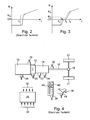
- Fig. 2 schematically shows the structure of a per se known vehicle drive train:
- a vehicle drive motor 10 for example an internal combustion engine, is connected via a clutch 12 to a transmission 14 whose output shaft drives a vehicle via a propeller shaft 16 and a differential 18 wheels 21.
- the clutch 12 is an automated clutch, which is actuated by means of an actuator 20.
- the transmission 14 is, for example, an automated transmission operated by a shift actuator 22 and a select actuator 24.
- an electronic control device 28 For controlling said actuators and a further actuator 26 for actuating a load actuator of the vehicle drive motor, an electronic control device 28 is provided with a microprocessor and associated memory devices whose outputs 30 control the operation of the actuators 20, 22, 24 and 26 and the inputs 32 in the Powertrain provided sensors for detecting relevant for the actuation of the actuators operating parameters are connected, for example, a speed sensor 34 for detecting the rotational speed of the output shaft of the drive motor 10, a speed sensor 36 for detecting the rotational speed of the propeller shaft 16, a position sensor 38, for detecting the position of a Selector lever 40 of a Fahrprogramm reachl coupled 42 and a position sensor 44 for detecting the position of an accelerator pedal 46th
- a clutch characteristic is stored in the electronic control device 28, which is adapted or updated at predetermined operating conditions and indicates the clutch torque in dependence on the position of the clutch actuator 20.
- the clutch 12 is actuated such that it is fully open when laying out a gear and inserting a new gear and then, for example, depending on the position of the accelerator pedal 46 and optionally further operating parameters of the drive train is closed until they are from the engine delivered torque at least substantially slip-free transmits.
- a problem that occurs with known gearshifts is that, for example, starting from fully open clutch (transmittable clutch torque substantially equal to zero) after inserting a new gear, the clutch quickly closes to transmit a high output from the drive motor 10 torque and thereby their gripping point reached within a short time and overrun. In practice, this leads to uncomfortable blows that already occur when the clutch reaches its gripping point and thereby existing on the drive train games are recorded.
- elastically suspended in the vehicle chassis vehicle drive motor preferably an internal combustion engine, come to support the torque transmitted from the drive train in abutment with the elastic limits or attacks the engine mount.
- a method for suppressing vibrations in the drive train of a motor vehicle driven by an internal combustion engine in which the internal combustion engine is supplied in the occurrence of vibrations in the drive train in a correction device determined, the drive torque of the internal combustion engine changing control variable.
- This speed information becomes a speed gradient determined and used for vibration assessment. This makes it possible to change the drive torque of the internal combustion engine such that the vibrations in the drive train are damped by an in-phase changeover from the ignition times of an ignition map stored in an ignition control device to corresponding ignition times of a second ignition map stored in the ignition control device.
- the invention has for its object to provide a method and an apparatus with which or the switching shocks can be avoided in a provided with an automatic clutch drive train of a vehicle or at least greatly attenuated.
- the claim 1 is directed to a method for the solution of the invention task.
- the claim 5 indicates the basic structure of a device for solving the invention task.
- the clutch for engaging a new gear of a transmission contained in the drive train is fully opened and after engaging the new gear with a predetermined speed course through its gripping point closed through.
- the predetermined speed curve depends on at least one of the following operating parameters of the drive train: position of an accelerator pedal, engaged gear, torque of a vehicle drive motor, speed difference at the clutch.
- the predetermined speed profile may be a predetermined constant speed.
- the clutch as soon as after passing through the gripping point a predetermined first clutch torque is transmitted, closed at an increased speed until a predetermined second clutch torque is transmitted.
- the torque output by a vehicle drive motor contained in the drive train is set to zero or thrust during opening of the clutch for a gear change, from the time the clutch is fully opened until the new gear is engaged to a value of at least approximately zero after inserting the new gear, while the clutch is closed by the gripping point through, increases with a predetermined speed curve, the engine speed after inserting the new gear at least until passing through the gripping point of the clutch at a traction circuit constantly at a higher speed is held as the output side of the clutch and is held at a lower-speed thrust circuit than the output side of the clutch.
- An apparatus for reducing shift shocks in an automatic clutch driveline of a vehicle propulsion engine includes electronic control means having inputs coupled to sensors for sensing driveline operating parameters, an output connected to a clutch actuator for controlling the clutch Output, which is connected to a Stellaktor for providing a load actuator of a vehicle drive motor, a data memory in which at least one of the Aufziehmoment the drive train corresponding value is stored, and a program memory in which at least one program for performing the method is controlled.
- FIG. 1 illustrating a simplified flow diagram of a method according to the invention
- the shift command activates a program to perform the shift in step 60 by first opening the clutch in step 62 as usual, and substantially simultaneously in step 64, setting the engine load or engine torque to thrust, for example by cutting off power becomes. This ensures that the engine speed drops rapidly.
- step 64 it is checked whether the clutch is fully open. If this is the case, the transmission operating device is activated in step 66 and the old gear is designed and the new gear is engaged. At the same time, the engine torque is set to zero in step 68 by corresponding actuation of a load actuator, so that the engine is running at least at its idle speed. If it is determined in step 70 that the new gear is engaged, the engine torque is increased to a torque greater than zero in step 72 and then further increased with a predetermined ramp or time change. At the same time, in step 74, the clutch is first actuated rapidly to near its gripping point and then at a predetermined rate of travel through the gripping point.
- the clutch can be closed at a faster speed until a desired clutch torque is reached, which depends for example on the position of the accelerator pedal.
- the preferably slow closing of the clutch through the gripping point is preferably carried out under conditions in which, in a traction circuit, in particular traction upshift, the engine-side speed of the clutch is greater than the transmission-side speed, so that the closing clutch tends to lower the engine speed.
- the step 74 is in thrust circuits, in particular thrust shifts in a lower gear, under conditions in which the engine-side Speed of the clutch is below the transmission-side speed.
- the appropriate speed curve of the engine speed is set in each case in step 72.
- step 76 If it is determined in step 76 that the clutch is closed so far that the predetermined clutch torque is achieved, for example, corresponds to a value at which the elasticities of the drive train are largely used up, so the drive train is "wound up", the clutch is preferably with greater actuation speed than in step 76 in step 78 closed until it transmits a desired torque.
- step 80 the program returns to a normal program in step 82.
- FIGS. 2 and 3 illustrates that represent a conventional associated with a switching operation clutch operation and a clutch operation according to the invention over time.
- the ordinate represents the transmittable clutch torque N, where GP represents the gripping point of the clutch (transmissible clutch torque of a few Nm).
- the abscissa indicates the time.
- a known clutch actuation takes place such that, as soon as a new gear is engaged (time t1), the fully opened clutch preferably closed as fast as the clutch actuator, to a clutch desired torque KS, which depends for example on the position of the accelerator pedal and the new gear , As soon as the desired clutch torque KS has been reached, the clutch continues to be closed depending on operating parameters of the vehicle drive train, for example.
- the period t1 to t3 corresponds to the step 74 of FIG Fig. 1
- the time t3 to t4 corresponds to the step 78 of FIG Fig. 1
- the dashed line represents one in each case in the control device 28 (FIG. Fig. 4 ) calculated clutch desired torque curve; the solid line represents the actual course of the clutch torque, which follows the desired course with a time delay.
- step 64 the engine torque does not necessarily have to be set to thrust, but can be kept speed-controlled, for example in a power upshift to a value corresponding to the previous speed in the lower gear, so that the engine after inserting the new gear (step 66), by then also speed controlled in place of step 68, in step 72 first continues on the previous speed and its speed then increases. This ensures that when gripping the clutch in step 76 at Werchescigenen the entire drive train is in a tensile state.
- the engine torque may be maintained at zero during steps 64, 68, and 72, or the engine speed may be controlled to be less than a value equal to the speed in the new gear when the clutch is fully engaged.
- the ramping engine torque may be controlled to maximally increase to a value that depends on the position of the accelerator pedal.
- step 74 the clutch initially closes with a predetermined course until the gripping point is reached, is a soft and not associated with alternating stresses Torque engagement of the drivetrain achieved with the vibrations in the drive train can be reduced or even completely suppressed.
- the clutch does not necessarily have to be actuated very quickly to approximately the gripping point, but can already be closed from the time t1 with the predetermined slowed speed course through the gripping point, especially if the clutch during the gear changes not significantly beyond the gripping point is opened.
- the comparison with the clutch actuation between the times t1 and t3 faster actuation between the times t3 and t4 is also not mandatory. It merely serves to shorten the time until reaching the desired clutch torque at which the normal program is transferred.
- the engine torque increase in step 72 may be such that it is slower to reach the gripping point of the clutch than subsequently.
- a rapid increase in engine torque at the beginning of step 72 to a value greater than zero serves to ensure that at a Switzerlandhochsciens the motor-side shaft of the clutch rotates faster than the transmission side.
- An essential feature of the method according to the invention is that the clutch reaches the gripping point with a predetermined speed profile, which may be dependent on operating parameters of the drive train, and possibly passes through, which is sufficiently slow, so that no impulsive loads occur when the drive train is acted upon by the engine and / or alternating stresses that can lead to vibrations.
- the invention can be used for automated manual transmissions and manual transmissions, with manual transmissions a sensor attached to the transmission detecting that a new gear is fully engaged.
Landscapes
- Engineering & Computer Science (AREA)
- General Engineering & Computer Science (AREA)
- Physics & Mathematics (AREA)
- Fluid Mechanics (AREA)
- Mechanical Engineering (AREA)
- Control Of Driving Devices And Active Controlling Of Vehicle (AREA)
- Hydraulic Clutches, Magnetic Clutches, Fluid Clutches, And Fluid Joints (AREA)
Applications Claiming Priority (1)
| Application Number | Priority Date | Filing Date | Title |
|---|---|---|---|
| DE102007024132 | 2007-05-24 |
Publications (1)
| Publication Number | Publication Date |
|---|---|
| EP1995486A2 true EP1995486A2 (fr) | 2008-11-26 |
Family
ID=39712218
Family Applications (1)
| Application Number | Title | Priority Date | Filing Date |
|---|---|---|---|
| EP08008816A Withdrawn EP1995486A2 (fr) | 2007-05-24 | 2008-05-13 | Procédé et dispositif destinés à éviter des vibrations produites par le changement de vitesses dans la chaîne cinématique d'un véhicule |
Country Status (2)
| Country | Link |
|---|---|
| EP (1) | EP1995486A2 (fr) |
| DE (1) | DE102008023359A1 (fr) |
Cited By (1)
| Publication number | Priority date | Publication date | Assignee | Title |
|---|---|---|---|---|
| CN118274122A (zh) * | 2024-06-04 | 2024-07-02 | 江苏盛海智能科技有限公司 | 一种变速箱离合机构的高效运行方法及终端 |
Citations (1)
| Publication number | Priority date | Publication date | Assignee | Title |
|---|---|---|---|---|
| DE4009791A1 (de) | 1990-03-27 | 1991-10-02 | Daimler Benz Ag | Verfahren zur unterdrueckung von schwingungen im antriebsstrang eines kraftfahrzeuges |
-
2008
- 2008-05-13 DE DE102008023359A patent/DE102008023359A1/de not_active Ceased
- 2008-05-13 EP EP08008816A patent/EP1995486A2/fr not_active Withdrawn
Patent Citations (1)
| Publication number | Priority date | Publication date | Assignee | Title |
|---|---|---|---|---|
| DE4009791A1 (de) | 1990-03-27 | 1991-10-02 | Daimler Benz Ag | Verfahren zur unterdrueckung von schwingungen im antriebsstrang eines kraftfahrzeuges |
Cited By (1)
| Publication number | Priority date | Publication date | Assignee | Title |
|---|---|---|---|---|
| CN118274122A (zh) * | 2024-06-04 | 2024-07-02 | 江苏盛海智能科技有限公司 | 一种变速箱离合机构的高效运行方法及终端 |
Also Published As
| Publication number | Publication date |
|---|---|
| DE102008023359A1 (de) | 2008-11-27 |
Similar Documents
| Publication | Publication Date | Title |
|---|---|---|
| EP3668737B1 (fr) | Ensemble boîte de vitesses de motorisation hybride et procédé pour faire fonctionner un véhicule à motorisation hybride | |
| DE102008027071A1 (de) | Verfahren und Vorrichtung zur Reibwertadaption einer in einem Hybridantriebsstrang angeordneten Reibungskupplung | |
| EP1554152B1 (fr) | Procede pour commander une chaine cinematique comprenant un embrayage semi-automatique | |
| EP2016312A1 (fr) | Procédé et dispositif pour adapter la commande des embrayages d'une transmission à double embrayage | |
| WO2013124122A1 (fr) | Procédé de détermination d'une commande de couple d'embrayage | |
| WO2007042141A2 (fr) | Procede et dispositif permettant de commander un changement de rapport d'une boite de vitesses automatique | |
| EP1564446B1 (fr) | Méthode et dispostif de commande de changement de vitesse pour transmission véhiculaire à changement parallèle | |
| DE10135327A1 (de) | Automatisiertes Zahnräderwechselgetriebe und Verfahren zum Gangwechsel bei einem solchen | |
| DE19841856C1 (de) | Verfahren zum Durchführen von Schaltprozeduren | |
| DE102014008672B4 (de) | Verfahren zum Betreiben einer Getriebeeinrichtung für ein Kraftfahrzeug sowie entsprechende Getriebeeinrichtung | |
| DE112008000375B4 (de) | Verfahren und Vorrichtung zum Steuern der Kupplungen eines Parallelschaltgetriebes bei einem Gangwechsel | |
| EP1382479B1 (fr) | Méthode de démarrage d'un système de transmission de véhicule avec une boîte de vitesse à double embrayage | |
| EP2196706B1 (fr) | Dispositif et procédé de commande d'une transmission à double embrayages | |
| EP1753982B1 (fr) | Procede de commande d'une transmission automatique | |
| DE102018221532A1 (de) | Ermittlung eines Anlegepunktes einer Kupplung | |
| DE19904129C1 (de) | Verfahren zur Durchführung von Schaltvorgängen bei einem Antriebssystem | |
| EP1910699B1 (fr) | Procede et dispositif de commande permettant de regler une vitesse de rotation d'un arbre d'une boite de vitesses a engrenages | |
| DE102008046849A1 (de) | Verfahren und Steuereinrichtung zur Steuerung eines Verbrennungsmotors eines Triebstrangs eines Kraftfahrzeugs | |
| EP1995486A2 (fr) | Procédé et dispositif destinés à éviter des vibrations produites par le changement de vitesses dans la chaîne cinématique d'un véhicule | |
| DE102010024938A1 (de) | Verfahren zur Regelung eines Antriebsstrangs mit automatischer Reibungskupplung und Antriebsstrang hierzu | |
| DE102006024277A1 (de) | Verfahren und Vorrichtung zur Steuerung eines automatisierten Schaltgetriebes | |
| DE102015223899A1 (de) | Verfahren zum Schalten eines Motorradgetriebes | |
| WO2011100950A1 (fr) | Procédé pour commander un embrayage à friction | |
| WO2007071300A1 (fr) | Procede de commutation d'une boite de vitesses automatisee | |
| DE102018220413A1 (de) | Verfahren zum Durchführen eines Gangwechsels, Steuerungseinrichtung sowie Kraftfahrzeug |
Legal Events
| Date | Code | Title | Description |
|---|---|---|---|
| PUAI | Public reference made under article 153(3) epc to a published international application that has entered the european phase |
Free format text: ORIGINAL CODE: 0009012 |
|
| AK | Designated contracting states |
Kind code of ref document: A2 Designated state(s): AT BE BG CH CY CZ DE DK EE ES FI FR GB GR HR HU IE IS IT LI LT LU LV MC MT NL NO PL PT RO SE SI SK TR |
|
| AX | Request for extension of the european patent |
Extension state: AL BA MK RS |
|
| RIN1 | Information on inventor provided before grant (corrected) |
Inventor name: YASIN, MOHAMMED Inventor name: GALLION, MICHAEL Inventor name: UDDIN, SHAFIQ Inventor name: SONG, INHO |
|
| STAA | Information on the status of an ep patent application or granted ep patent |
Free format text: STATUS: THE APPLICATION IS DEEMED TO BE WITHDRAWN |
|
| 18D | Application deemed to be withdrawn |
Effective date: 20101201 |
|
| P01 | Opt-out of the competence of the unified patent court (upc) registered |
Effective date: 20230523 |