EP1995466B1 - Blade of impeller for centrifugal fan, rotating body for supporting blades, impeller for centrifugal fan, and method of producing impeller for centrifugal fan - Google Patents
Blade of impeller for centrifugal fan, rotating body for supporting blades, impeller for centrifugal fan, and method of producing impeller for centrifugal fan Download PDFInfo
- Publication number
- EP1995466B1 EP1995466B1 EP07737810.7A EP07737810A EP1995466B1 EP 1995466 B1 EP1995466 B1 EP 1995466B1 EP 07737810 A EP07737810 A EP 07737810A EP 1995466 B1 EP1995466 B1 EP 1995466B1
- Authority
- EP
- European Patent Office
- Prior art keywords
- blade
- weld
- rotator
- blades
- impeller
- Prior art date
- Legal status (The legal status is an assumption and is not a legal conclusion. Google has not performed a legal analysis and makes no representation as to the accuracy of the status listed.)
- Not-in-force
Links
Images


Classifications
-
- B—PERFORMING OPERATIONS; TRANSPORTING
- B21—MECHANICAL METAL-WORKING WITHOUT ESSENTIALLY REMOVING MATERIAL; PUNCHING METAL
- B21K—MAKING FORGED OR PRESSED METAL PRODUCTS, e.g. HORSE-SHOES, RIVETS, BOLTS OR WHEELS
- B21K3/00—Making engine or like machine parts not covered by sub-groups of B21K1/00; Making propellers or the like
- B21K3/04—Making engine or like machine parts not covered by sub-groups of B21K1/00; Making propellers or the like blades, e.g. for turbines; Upsetting of blade roots
-
- F—MECHANICAL ENGINEERING; LIGHTING; HEATING; WEAPONS; BLASTING
- F04—POSITIVE - DISPLACEMENT MACHINES FOR LIQUIDS; PUMPS FOR LIQUIDS OR ELASTIC FLUIDS
- F04D—NON-POSITIVE-DISPLACEMENT PUMPS
- F04D29/00—Details, component parts, or accessories
- F04D29/02—Selection of particular materials
- F04D29/023—Selection of particular materials especially adapted for elastic fluid pumps
-
- F—MECHANICAL ENGINEERING; LIGHTING; HEATING; WEAPONS; BLASTING
- F04—POSITIVE - DISPLACEMENT MACHINES FOR LIQUIDS; PUMPS FOR LIQUIDS OR ELASTIC FLUIDS
- F04D—NON-POSITIVE-DISPLACEMENT PUMPS
- F04D29/00—Details, component parts, or accessories
- F04D29/26—Rotors specially for elastic fluids
- F04D29/28—Rotors specially for elastic fluids for centrifugal or helico-centrifugal pumps for radial-flow or helico-centrifugal pumps
- F04D29/281—Rotors specially for elastic fluids for centrifugal or helico-centrifugal pumps for radial-flow or helico-centrifugal pumps for fans or blowers
-
- F—MECHANICAL ENGINEERING; LIGHTING; HEATING; WEAPONS; BLASTING
- F04—POSITIVE - DISPLACEMENT MACHINES FOR LIQUIDS; PUMPS FOR LIQUIDS OR ELASTIC FLUIDS
- F04D—NON-POSITIVE-DISPLACEMENT PUMPS
- F04D29/00—Details, component parts, or accessories
- F04D29/26—Rotors specially for elastic fluids
- F04D29/28—Rotors specially for elastic fluids for centrifugal or helico-centrifugal pumps for radial-flow or helico-centrifugal pumps
- F04D29/30—Vanes
-
- F—MECHANICAL ENGINEERING; LIGHTING; HEATING; WEAPONS; BLASTING
- F04—POSITIVE - DISPLACEMENT MACHINES FOR LIQUIDS; PUMPS FOR LIQUIDS OR ELASTIC FLUIDS
- F04D—NON-POSITIVE-DISPLACEMENT PUMPS
- F04D29/00—Details, component parts, or accessories
- F04D29/60—Mounting; Assembling; Disassembling
- F04D29/62—Mounting; Assembling; Disassembling of radial or helico-centrifugal pumps
- F04D29/624—Mounting; Assembling; Disassembling of radial or helico-centrifugal pumps especially adapted for elastic fluid pumps
- F04D29/626—Mounting or removal of fans
-
- B—PERFORMING OPERATIONS; TRANSPORTING
- B29—WORKING OF PLASTICS; WORKING OF SUBSTANCES IN A PLASTIC STATE IN GENERAL
- B29C—SHAPING OR JOINING OF PLASTICS; SHAPING OF MATERIAL IN A PLASTIC STATE, NOT OTHERWISE PROVIDED FOR; AFTER-TREATMENT OF THE SHAPED PRODUCTS, e.g. REPAIRING
- B29C65/00—Joining or sealing of preformed parts, e.g. welding of plastics materials; Apparatus therefor
- B29C65/02—Joining or sealing of preformed parts, e.g. welding of plastics materials; Apparatus therefor by heating, with or without pressure
- B29C65/14—Joining or sealing of preformed parts, e.g. welding of plastics materials; Apparatus therefor by heating, with or without pressure using wave energy, i.e. electromagnetic radiation, or particle radiation
- B29C65/16—Laser beams
- B29C65/1629—Laser beams characterised by the way of heating the interface
- B29C65/1635—Laser beams characterised by the way of heating the interface at least passing through one of the parts to be joined, i.e. laser transmission welding
-
- B—PERFORMING OPERATIONS; TRANSPORTING
- B29—WORKING OF PLASTICS; WORKING OF SUBSTANCES IN A PLASTIC STATE IN GENERAL
- B29C—SHAPING OR JOINING OF PLASTICS; SHAPING OF MATERIAL IN A PLASTIC STATE, NOT OTHERWISE PROVIDED FOR; AFTER-TREATMENT OF THE SHAPED PRODUCTS, e.g. REPAIRING
- B29C66/00—General aspects of processes or apparatus for joining preformed parts
- B29C66/01—General aspects dealing with the joint area or with the area to be joined
- B29C66/05—Particular design of joint configurations
- B29C66/10—Particular design of joint configurations particular design of the joint cross-sections
- B29C66/12—Joint cross-sections combining only two joint-segments; Tongue and groove joints; Tenon and mortise joints; Stepped joint cross-sections
- B29C66/124—Tongue and groove joints
- B29C66/1246—Tongue and groove joints characterised by the female part, i.e. the part comprising the groove
- B29C66/12469—Tongue and groove joints characterised by the female part, i.e. the part comprising the groove being asymmetric
-
- B—PERFORMING OPERATIONS; TRANSPORTING
- B29—WORKING OF PLASTICS; WORKING OF SUBSTANCES IN A PLASTIC STATE IN GENERAL
- B29C—SHAPING OR JOINING OF PLASTICS; SHAPING OF MATERIAL IN A PLASTIC STATE, NOT OTHERWISE PROVIDED FOR; AFTER-TREATMENT OF THE SHAPED PRODUCTS, e.g. REPAIRING
- B29C66/00—General aspects of processes or apparatus for joining preformed parts
- B29C66/50—General aspects of joining tubular articles; General aspects of joining long products, i.e. bars or profiled elements; General aspects of joining single elements to tubular articles, hollow articles or bars; General aspects of joining several hollow-preforms to form hollow or tubular articles
- B29C66/51—Joining tubular articles, profiled elements or bars; Joining single elements to tubular articles, hollow articles or bars; Joining several hollow-preforms to form hollow or tubular articles
- B29C66/53—Joining single elements to tubular articles, hollow articles or bars
- B29C66/534—Joining single elements to open ends of tubular or hollow articles or to the ends of bars
- B29C66/5344—Joining single elements to open ends of tubular or hollow articles or to the ends of bars said single elements being substantially annular, i.e. of finite length, e.g. joining flanges to tube ends
-
- B—PERFORMING OPERATIONS; TRANSPORTING
- B29—WORKING OF PLASTICS; WORKING OF SUBSTANCES IN A PLASTIC STATE IN GENERAL
- B29C—SHAPING OR JOINING OF PLASTICS; SHAPING OF MATERIAL IN A PLASTIC STATE, NOT OTHERWISE PROVIDED FOR; AFTER-TREATMENT OF THE SHAPED PRODUCTS, e.g. REPAIRING
- B29C66/00—General aspects of processes or apparatus for joining preformed parts
- B29C66/50—General aspects of joining tubular articles; General aspects of joining long products, i.e. bars or profiled elements; General aspects of joining single elements to tubular articles, hollow articles or bars; General aspects of joining several hollow-preforms to form hollow or tubular articles
- B29C66/51—Joining tubular articles, profiled elements or bars; Joining single elements to tubular articles, hollow articles or bars; Joining several hollow-preforms to form hollow or tubular articles
- B29C66/53—Joining single elements to tubular articles, hollow articles or bars
- B29C66/534—Joining single elements to open ends of tubular or hollow articles or to the ends of bars
- B29C66/5346—Joining single elements to open ends of tubular or hollow articles or to the ends of bars said single elements being substantially flat
-
- B—PERFORMING OPERATIONS; TRANSPORTING
- B29—WORKING OF PLASTICS; WORKING OF SUBSTANCES IN A PLASTIC STATE IN GENERAL
- B29C—SHAPING OR JOINING OF PLASTICS; SHAPING OF MATERIAL IN A PLASTIC STATE, NOT OTHERWISE PROVIDED FOR; AFTER-TREATMENT OF THE SHAPED PRODUCTS, e.g. REPAIRING
- B29C66/00—General aspects of processes or apparatus for joining preformed parts
- B29C66/50—General aspects of joining tubular articles; General aspects of joining long products, i.e. bars or profiled elements; General aspects of joining single elements to tubular articles, hollow articles or bars; General aspects of joining several hollow-preforms to form hollow or tubular articles
- B29C66/51—Joining tubular articles, profiled elements or bars; Joining single elements to tubular articles, hollow articles or bars; Joining several hollow-preforms to form hollow or tubular articles
- B29C66/54—Joining several hollow-preforms, e.g. half-shells, to form hollow articles, e.g. for making balls, containers; Joining several hollow-preforms, e.g. half-cylinders, to form tubular articles
- B29C66/543—Joining several hollow-preforms, e.g. half-shells, to form hollow articles, e.g. for making balls, containers; Joining several hollow-preforms, e.g. half-cylinders, to form tubular articles joining more than two hollow-preforms to form said hollow articles
-
- B—PERFORMING OPERATIONS; TRANSPORTING
- B29—WORKING OF PLASTICS; WORKING OF SUBSTANCES IN A PLASTIC STATE IN GENERAL
- B29L—INDEXING SCHEME ASSOCIATED WITH SUBCLASS B29C, RELATING TO PARTICULAR ARTICLES
- B29L2031/00—Other particular articles
- B29L2031/08—Blades for rotors, stators, fans, turbines or the like, e.g. screw propellers
-
- F—MECHANICAL ENGINEERING; LIGHTING; HEATING; WEAPONS; BLASTING
- F05—INDEXING SCHEMES RELATING TO ENGINES OR PUMPS IN VARIOUS SUBCLASSES OF CLASSES F01-F04
- F05D—INDEXING SCHEME FOR ASPECTS RELATING TO NON-POSITIVE-DISPLACEMENT MACHINES OR ENGINES, GAS-TURBINES OR JET-PROPULSION PLANTS
- F05D2230/00—Manufacture
- F05D2230/20—Manufacture essentially without removing material
- F05D2230/23—Manufacture essentially without removing material by permanently joining parts together
- F05D2230/232—Manufacture essentially without removing material by permanently joining parts together by welding
-
- F—MECHANICAL ENGINEERING; LIGHTING; HEATING; WEAPONS; BLASTING
- F05—INDEXING SCHEMES RELATING TO ENGINES OR PUMPS IN VARIOUS SUBCLASSES OF CLASSES F01-F04
- F05D—INDEXING SCHEME FOR ASPECTS RELATING TO NON-POSITIVE-DISPLACEMENT MACHINES OR ENGINES, GAS-TURBINES OR JET-PROPULSION PLANTS
- F05D2300/00—Materials; Properties thereof
- F05D2300/40—Organic materials
- F05D2300/44—Resins
-
- Y—GENERAL TAGGING OF NEW TECHNOLOGICAL DEVELOPMENTS; GENERAL TAGGING OF CROSS-SECTIONAL TECHNOLOGIES SPANNING OVER SEVERAL SECTIONS OF THE IPC; TECHNICAL SUBJECTS COVERED BY FORMER USPC CROSS-REFERENCE ART COLLECTIONS [XRACs] AND DIGESTS
- Y10—TECHNICAL SUBJECTS COVERED BY FORMER USPC
- Y10T—TECHNICAL SUBJECTS COVERED BY FORMER US CLASSIFICATION
- Y10T29/00—Metal working
- Y10T29/49—Method of mechanical manufacture
- Y10T29/49316—Impeller making
- Y10T29/4932—Turbomachine making
- Y10T29/49321—Assembling individual fluid flow interacting members, e.g., blades, vanes, buckets, on rotary support member
-
- Y—GENERAL TAGGING OF NEW TECHNOLOGICAL DEVELOPMENTS; GENERAL TAGGING OF CROSS-SECTIONAL TECHNOLOGIES SPANNING OVER SEVERAL SECTIONS OF THE IPC; TECHNICAL SUBJECTS COVERED BY FORMER USPC CROSS-REFERENCE ART COLLECTIONS [XRACs] AND DIGESTS
- Y10—TECHNICAL SUBJECTS COVERED BY FORMER USPC
- Y10T—TECHNICAL SUBJECTS COVERED BY FORMER US CLASSIFICATION
- Y10T29/00—Metal working
- Y10T29/49—Method of mechanical manufacture
- Y10T29/49316—Impeller making
- Y10T29/49327—Axial blower or fan
-
- Y—GENERAL TAGGING OF NEW TECHNOLOGICAL DEVELOPMENTS; GENERAL TAGGING OF CROSS-SECTIONAL TECHNOLOGIES SPANNING OVER SEVERAL SECTIONS OF THE IPC; TECHNICAL SUBJECTS COVERED BY FORMER USPC CROSS-REFERENCE ART COLLECTIONS [XRACs] AND DIGESTS
- Y10—TECHNICAL SUBJECTS COVERED BY FORMER USPC
- Y10T—TECHNICAL SUBJECTS COVERED BY FORMER US CLASSIFICATION
- Y10T29/00—Metal working
- Y10T29/49—Method of mechanical manufacture
- Y10T29/49316—Impeller making
- Y10T29/49329—Centrifugal blower or fan
-
- Y—GENERAL TAGGING OF NEW TECHNOLOGICAL DEVELOPMENTS; GENERAL TAGGING OF CROSS-SECTIONAL TECHNOLOGIES SPANNING OVER SEVERAL SECTIONS OF THE IPC; TECHNICAL SUBJECTS COVERED BY FORMER USPC CROSS-REFERENCE ART COLLECTIONS [XRACs] AND DIGESTS
- Y10—TECHNICAL SUBJECTS COVERED BY FORMER USPC
- Y10T—TECHNICAL SUBJECTS COVERED BY FORMER US CLASSIFICATION
- Y10T29/00—Metal working
- Y10T29/49—Method of mechanical manufacture
- Y10T29/49316—Impeller making
- Y10T29/49336—Blade making
Description
- The present invention relates to an impeller blade for a centrifugal blower, a blade-supporting rotator, an impeller for a centrifugal blower, and a method for manufacturing an impeller for a centrifugal blower. The present invention particularly relates to an impeller blade for a centrifugal blower, a blade-supporting rotator, an impeller for a centrifugal blower, and a method for manufacturing an impeller for a centrifugal blower wherein the centrifugal blower is configured by fixing resinous blades having hollow spaces formed in interiors thereof to a resinous blade-supporting rotator by laser welding.
- Conventionally, turbofans, diagonal-flow fans, and other such centrifugal blowers have been used in ventilation apparatuses, air conditioning apparatuses, air purifiers, and the like. An impeller for this type of centrifugal blower comprises a resinous end plate rotated around a rotational axis by a motor or another such drive mechanism, a plurality of resinous blades having hollow spaces formed in interiors thereof, and a resinous end ring disposed so as to sandwich the blades between the axial direction of the ring and the axial direction of the end plate, as shown in
Patent Document 1. The hollow spaces in the blades are formed by attaching two plate-shaped members together, and the blades are fixed to the end plate or the end ring by laser welding. - Similar impellers are also known from
US 694 881 A andJP-550-45445 A - <
PatentDocument 1> Japanese Laid-open Patent Application No.2005-155510 - In cases in which a structure is used in which resinous blades having hollow spaces formed in interiors thereof are fixed to a resinous end plate or a resinous end ring by laser welding as described above, adherence is important between the weld surfaces of the blades and the weld surface of the end plate, or between the weld surfaces of the blades and the weld surface of the end ring. If adherence between the weld surfaces of the members is insufficient and large gaps form between the weld surfaces, cases may arise in which sufficient welding strength is not achieved.
- For example, in blades, end plates, or end rings molded from a resin, unevenness form to some degree in the weld surfaces of the members depending on the finishing precision during resin molding, and cases arise in which the gaps between the weld surfaces of the members become large depending on the unevenness, and sufficient welding strength is not achieved.
- When laser welding is performed, a load is imposed to press the end plate and the blades each other in the axial direction, or a load is imposed to press the end ring and the blades each other in the axial direction in order to achieve satisfactory adherence between the weld surfaces of the blades and the weld surface of the end plate, or between the weld surfaces of the blades and the weld surface of the end ring. At this time, however, in cases in which the blades are thin or the blades have a complex rounded shape such that the axially central portions of the blades protrude in the radial direction of the impeller, the blades bend due to a load axially compressing the blades when the aforementioned pressure load is imposed, whereby cases arise in which large gaps form between the weld surfaces of the blades and the weld surface of the end plate, or between the weld surfaces of the blades and the weld surface of the end ring, and sufficient welding strength cannot be achieved.
- Thus, in cases in which a structure is used in which resinous hollow blades are fixed by laser welding to a blade-supporting rotator such as a resinous end plate or a resinous end ring, it is difficult to achieve "adherence between the weld surfaces of the members," which has a great affect on welding strength, and as a result, cases may arise in which sufficient welding strength is not achieved. This tendency becomes greater particularly in cases in which the blades are given a complex rounded shape in order to improve blowing performance or noise quality, or in cases in which the blades are thinned in order to reduce the weight of the impeller.
- An object of the present invention is to ensure that adherence is satisfactory between the weld surfaces of blades and the weld surface of a blade-supporting rotator, and that welding strength is achieved in a stable manner, in an impeller for a centrifugal blower configured by using laser welding to fix resinous blades having hollow spaces formed in interiors thereof to a resinous blade-supporting rotator.
- The impeller blade for a centrifugal blower according to a first aspect is an impeller blade for a centrifugal blower in which a plurality of blades are arranged annularly around a rotational axis of a resinous blade-supporting rotator which rotates around the axis, the blades being fixed by laser welding to rotator weld surfaces formed on one side surface in the axial direction of the blade-supporting rotator; wherein the impeller blade is a resinous hollow blade having blade weld part welded to the rotator weld surface at one end, a hollow space being formed in the blade interior; and a blade weld surface inclined with respect to the rotator weld surface is formed in the blade weld part in a state in which the blade weld part is disposed to face the rotator weld surface in the axial direction.
- With this impeller blade for a centrifugal blower, when a load is applied so as to press the blade-supporting rotator and the blade each other in the axial direction as the blade is fixed by laser welding to the blade-supporting rotators, the portion in proximity to the rotator weld surface formed by the inclining of the blade weld surface is firmly pressed into the rotator weld surface in a state in which the blade weld part is disposed to face the rotator weld surface in the axial direction. As a result, the adherence between the blade weld surface and the rotator weld surface is satisfactory, and the blade can therefore be fixed to the blade-supporting rotator with high welding strength.
- With this impeller blade for a centrifugal blower, it is thereby possible to achieve satisfactory adherence between the blade weld surface of the blade and the rotator weld surface of the blade-supporting rotator, and to achieve welding strength in a stable manner, even in cases in which unevenness is formed in the weld surface due to the finishing precision during resin molding of the blade and the blade-supporting rotator. In cases in which the blade is given a complex rounded shape in order to improve blowing performance or noise quality or in cases in which the blade is thinned in order to reduce the weight of the impeller, when the pressure load such as is described above is applied, the load compressing the blade in the axial direction is applied, causing the blades to bend, and there is a danger that a gap will increase between the blade weld surface of the blade and the rotator weld surface of the blade-supporting rotator. However, with this impeller blade for a centrifugal blower, the pressure load can be concentrated in the portion in proximity to the rotator weld surface formed by the inclining of the blade weld surface. Therefore, the pressure load applied between the blade and the blade-supporting rotator can be reduced in comparison with cases in which an attempt is made to firmly adhere the entire un-inclined blade weld surface to the entire rotator weld surface of the blade-supporting rotator. There is thereby less danger that the gap will increase between the blade weld surface of the blade and the rotator weld surface of the blade-supporting rotator. It is also possible to achieve satisfactory adherence between the blade weld surface of the blade and the rotator weld surface of the blade-supporting rotator, and the welding strength can be achieved in a stable manner.
- The impeller blade for a centrifugal blower according to a second aspect is the impeller blade for a centrifugal blower according to the first aspect, wherein the blade weld surface is configured to be inclined at an angle of 0.5 degrees to 2.5 degrees with respect to the rotator weld surface.
- With this impeller blade for a centrifugal blower, since the angles of inclination of the blade weld surface with respect to the rotator weld surface is 0.5 degrees or more, the gap that may form between the blade weld surface of the blade and the rotator weld surface of the blade-supporting rotator can be reduced by applying the pressure load between the blade-supporting rotator and the blade in the axial direction, and an operation for firmly adhering the weld surface together can be reliably achieved. Moreover, since the angles of inclination of the blade weld surface with respect to the rotator weld surface is 2.5 degrees or less, it is possible to reduce the gap that may form between the blade weld surface of the blade and the rotator weld surface of the blade-supporting rotator without the orientation of the blade being greatly changed by the angles of inclination, and the operation for firmly adhering the weld surface together can be achieved.
- Thus, with this impeller blade for a centrifugal blower, it is possible to achieve the operation for reducing the gap that may form between the blade weld surface of the blade and the rotator weld surface of the blade-supporting rotator in a reliable manner, without the orientation of the blade being greatly changed by the angles of inclination.
- The impeller blade for a centrifugal blower according to a third aspect is the impeller blade for a centrifugal blower according to the first or second aspect, wherein the blade weld surface is inclined so as to be closer to the rotator weld surface as the blade weld surface is oriented in a direction substantially opposite a direction in which an axially central portion of the blade protrudes orthogonally in the axial direction by bending the blade during application of an axially compressing load.
- With this impeller blade for a centrifugal blower, when the pressure load is applied in the axial direction between the blade-supporting rotator and the blade as the blade is fixed by laser welding to the blade-supporting rotator, the axially compressing load is applied to the blade, the blade bends, and the axially central portion of the blade protrudes orthogonally in the axial direction. Therefore, the portion of the blade weld part on the side substantially opposite the side in which the axially central portion of the blade protrudes orthogonally in the axial direction is thereby inclined in a direction aparting from the axial direction with respect to the rotator weld surface, and the gap between the blade weld surface and the rotator weld surface tends to increase. However, with this impeller blade for a centrifugal blower, the blade weld surface is inclined so as to be closer to the rotator weld surface as the blade weld surface is oriented in the direction substantially opposite the direction in which the axially central portion of the blade protrudes orthogonally in the axial direction by bending the blade. Therefore, it is possible to maintain a state in which the gap is small between the rotator weld surface of the blade-supporting rotator, and the portion in the blade weld surface of the blade on the side substantially opposite to the side in which the axially central portion of the blade protrudes orthogonally in the axial direction. It is also possible to achieve satisfactory adherence between the blade weld surface of the blade and the rotator weld surface of the blade-supporting rotator, and the welding strength can be achieved in a stable manner.
- The impeller blade for a centrifugal blower according to a fourth aspect is the impeller blade for a centrifugal blower according to any of the first through third aspects, wherein the impeller blade includes a first blade surface part, and a second blade surface part attached to the first blade surface part to form the hollow space with the first blade surface part. The blade weld part is formed so as to extend from the blade-supporting rotator side end of the first blade surface part toward the second blade surface part. The blade weld surface is configured to be inclined so as to be closer to the rotator weld surface as the blade weld surface is oriented toward the second blade surface part.
- The impeller blade for a centrifugal blower is configured by attaching the second blade surface part to the first blade surface part, wherein the blade weld part is formed so as to extend from the blade-supporting rotator side end of the first blade surface part toward the second blade surface part. Therefore, when the pressure load is applied in the axial direction between the blade-supporting rotator and the blade as the blade is fixed by laser welding to the blade-supporting rotator, the portion of the blade weld part near the second blade surface part, which is less rigid than the portion near the first blade surface part, is inclined in the axial direction away from the rotator weld surface, and the gap between the blade weld surface and the rotator weld surface tends to increase. However, with this impeller blade for a centrifugal blower, since the blade weld surface is inclined so as to be closer to the rotator weld surface as the blade weld surface is oriented toward the second blade surface part, it is possible to maintain a state in which the gap is small between the portion of the blade weld surface of the blade near the second blade surface part and the rotator weld surface of the blade-supporting rotator. It is also possible to achieve satisfactory adherence between the blade weld surface of the blade and the rotator weld surface of the blade-supporting rotator, and the welding strength can be achieved in a stable manner.
- The impeller blade for a centrifugal blower according to a fifth aspect is the impeller blade for a centrifugal blower according to any of the first through fourth aspects, wherein a groove or slit is formed in the blade weld part.
- With this impeller blade for a centrifugal blower, in cases in which unevenness occurs in each of the weld surfaces due to the finishing precision during resin molding of the blade and the blade-supporting rotator, merely providing an incline to the blade weld surfaces gives rise to the danger that there will still be portions in which it is impossible to reduce the gap between the blade weld surface of the blade and the rotator weld surface of the blade-supporting rotator. However, with this impeller blade for a centrifugal blower, the groove or slit is formed in the blade weld part, whereby each of the portions of the blade weld part partitioned by the groove or slit is able to move as separate portions in the axial direction, with the groove or slit acting as a boundary. Therefore, it is possible to reduce the danger that there will still be portions in which it is impossible to reduce the gap between the blade weld surface of the blade and the rotator weld surface of the blade-supporting rotator. It is also possible to achieve satisfactory adherence between the blade weld surface of the blade and the rotator weld surface of the blade-supporting rotator, and the welding strength can be achieved in a stable manner. In cases in which the blade is made to bend by the application of the pressure load in the axial direction between the blade-supporting rotator and the blade as the blade is fixed by laser welding to the blade-supporting rotator, such as cases in which the blade is given a complex rounded shape in order to improve blowing performance or noise quality, or cases in which the blade is thinned in order to reduce the weight of the impeller, there may be portions in which the gap increases between the blade weld surface of the blade and the rotator weld surface of the blade-supporting rotator. Therefore, merely providing an incline to the blade weld surface gives rise to the danger that there will still be portions in which it is impossible to reduce the gap between the blade weld surface of the blade and the rotator weld surface of the blade-supporting rotator. However, the groove or slit is formed in the blade weld part, whereby the each portion of the blade weld part partitioned by the groove or slit is able to function as separate blade weld part, with the groove or slit acting as a boundary. Therefore, it is possible to reduce the danger that there will still be portions in which it is impossible to reduce the gap between the blade weld surface of the blade and the rotator weld surface of the blade-supporting rotator, even in cases in which the blade is made to bend by the application of the pressure load in the axial direction between the blade-supporting rotator and the blade. It is also possible to achieve satisfactory adherence between the blade weld surface of the blade and the rotator weld surface of the blade-supporting rotator, and the welding strength can be achieved in a stable manner.
- Thus, with this impeller blade for a centrifugal blower, not only the incline is provided to the blade weld surfaces, but also the groove or slit is formed in the blade weld part, and it is therefore possible to reduce the danger that there will still be portions in which it is impossible to reduce the gap between the blade weld surface of the blade and the rotator weld surface of the blade-supporting rotator. It is also possible to achieve satisfactory adherence between the blade weld surface of the blade and the rotator weld surface of the blade-supporting rotator, and the welding strength can be achieved in a stable manner.
- The impeller blade for a centrifugal blower according to a sixth aspect is the impeller blade for a centrifugal blower according to any of the first through fourth aspects, wherein blade flat surface, which is parallel to a rotator weld surface and which is disposed at positions axially farther away from the rotator weld surface than the portion of the blade weld surface in proximity to the rotator weld surface, is formed in the blade weld part in addition to the blade weld surface so as to be adjacent to the blade weld surface in a state in which the blade weld part is disposed to face the rotator weld surface in the axial direction, and a groove or slit is formed so as to correspond to a boundary between the blade weld surface and the blade flat surface.
- With this impeller blade for a centrifugal blower, the blade flat surface, which is parallel to a rotator weld surface and which is disposed at position axially farther away from the rotator weld surface than the portion of the blade weld surfaces in proximity to the rotator weld surface, is formed in the blade weld part in addition to the blade weld surfaces so as to be adjacent to the blade weld surface in a state in which the blade weld part is disposed to face the rotator weld surface in the axial direction, and the groove or slit is formed so as to correspond to the boundary between the blade weld surface and the blade flat surface, whereby the portion corresponding to the blade weld surface of the blade weld part partitioned by the groove or slit and the portion corresponding to the blade flat surfaces is able to move as separate portion in the axial direction, with the groove or slit acting as a boundary. When the pressure load is applied between the blade-supporting rotator and the blade, the pressure load can be reliably concentrated in the portion of the blade weld surface closer to the rotator weld surface than the blade flat surface, because only the portion of the blade weld part corresponding to the blade weld surface is moved axially by the pressure load, and the portion corresponding to the blade flat surface does not move readily in the axial direction. Therefore, when the blade is fixed by laser welding to the blade-supporting rotator, the pressure load applied between the blade-supporting rotator and the blade can be further reduced.
- The impeller for a centrifugal blower according to a seventh aspect comprises a blade-supporting rotator and a plurality of the impeller blades for a centrifugal blower according to any of the first through sixth aspects. The blade-supporting rotator is a resinous member that rotates around a rotational axis, and the blade-supporting rotator includes rotator weld parts having a rotator weld surface formed on one side surface in the axial direction. The impeller blades are disposed annularly around the axis of the blade-supporting rotator, and the impeller blades are fixed by laser welding to the rotator weld surfaces.
- The impeller for a centrifugal blower is manufactured by using laser welding to fix the blades to the blade-supporting rotator in a state in which the load is applied so as to press the blade-supporting rotator and the blades each other in the axial direction, the blades having blade weld surfaces inclined with respect to the rotator weld surfaces in a state in which the blade weld parts are disposed to face the rotator weld surfaces in the axial direction. The blades are therefore fixed to the blade-supporting rotator with high welding strength. Therefore, with this impeller for a centrifugal blower, when the blades are fixed by laser welding to the blade-supporting rotator, the pressure load applied in the axial direction between the blade-supporting rotator and the blades can be reduced, the length of the laser welded portions can be reduced, the blades can be given a complex rounded shape in order to improve blowing performance and noise quality, the blades can be thinned in order to reduce the weight of the impeller, and, as a result, costs can be reduced.
- The blade-supporting rotator of an impeller for a centrifugal blower according to an eighth aspect is blade-supporting rotator of an impeller for a centrifugal blower in which a plurality of resinous blades are disposed on one axial side, the blades being disposed annularly around a rotational axis and having hollow spaces in the blade interiors, and blade weld surfaces formed at one ends of the blades are fixed by laser welding to the blade-supporting rotator; wherein the blade-supporting rotator is a member which have rotator weld parts welded to the blade weld surfaces in the sides near the blades in the axial direction, and which rotate around a rotational axis; and rotator weld surfaces inclined with respect to the blade weld surfaces are formed in the rotator weld parts in a state in which the rotator weld parts are disposed to face the blade weld surfaces in the axial direction.
- With this blade-supporting rotator of an impeller for a centrifugal blower, when a load is applied so as to press the blade-supporting rotator and the blades each other in the axial direction as the blades are fixed by laser welding to the blade-supporting rotator, the portions in proximity to the blade weld surfaces formed by the inclining of the rotator weld surfaces are pressed more firmly into the blade weld surfaces than the other portions in a state in which the blade weld parts are disposed to face the blade weld surfaces in the axial direction. As a result, the adherence between the rotator weld surfaces and the blade weld surfaces is satisfactory, and the blades can therefore be fixed to the blade-supporting rotator with high welding strength.
- With this blade-supporting rotator of an impeller for a centrifugal blower, it is thereby possible to achieve satisfactory adherence between the blade weld surfaces of the blades and the rotator weld surfaces of the blade-supporting rotators, and to achieve welding strength in a stable manner, even in cases in which unevenness are formed in the weld surfaces due to the finishing precision during resin molding of the blades and the blade-supporting rotator. In cases in which the blades are given a complex rounded shape in order to improve blowing performance or noise quality or in cases in which the blades are thinned in order to reduce the weight of the impeller, when the pressure load such as is described above is applied, the load compressing the blades in the axial direction is applied, causing the blades to bend, and there is a danger that the gaps will increase between the blade weld surfaces of the blades and the rotator weld surfaces of the blade-supporting rotator. However, with this blade-supporting rotator of an impeller for a centrifugal blower, the pressure load can be concentrated in the portions in proximity to the blade weld surfaces formed by the inclining of the rotator weld surfaces. Therefore, the pressure load applied between the blade-supporting rotator and the blades can be reduced in comparison with cases in which an attempt is made to firmly adhere the entire un-inclined rotator weld surfaces to the entire blade weld surfaces of the blades. There is thereby less danger that the gaps will increase between the blade weld surfaces of the blades and the rotator weld surfaces of the blade-supporting rotator. It is also possible to achieve satisfactory adherence between the blade weld surfaces of the blades and the rotator weld surfaces of the blade-supporting rotator, and the welding strength can be achieved in a stable manner.
- The blade-supporting rotator of an impeller for a centrifugal blower according to a ninth aspect is the blade-supporting rotator of an impeller for a centrifugal blower according to the eighth aspect, wherein the rotator weld surfaces are configured to be inclined at an angle of 0.5 degrees to 2.5 degrees with respect to the blade weld surfaces.
- With this blade-supporting rotator of an impeller for a centrifugal blower, since the angles of inclination of the rotator weld surfaces with respect to the blade weld surfaces are 0.5 degrees or more, the gaps that may form between the blade weld surfaces of the blades and the rotator weld surfaces of the blade-supporting rotator can be reduced by applying the pressure load between the blade-supporting rotator and the blades in the axial direction, and an operation for firmly adhering the weld surfaces together can be reliably achieved. Moreover, since the angles of inclination of the rotator weld surfaces with respect to the blade weld surfaces are 2.5 degrees or less, it is possible to reduce the gaps that may form between the blade weld surfaces of the blades and the rotator weld surfaces of the blade-supporting rotator without the orientations of the blades being greatly changed by the angles of inclination, and the operation for firmly adhering the weld surfaces together can be achieved.
- Thus, with this blade-supporting rotator of an impeller for a centrifugal blower, it is possible to achieve the operation for reducing the gaps that may form between the blade weld surfaces of the blades and the rotator weld surfaces of the blade-supporting rotator in a reliable manner, without the orientation of the blades being greatly changed by the angles of inclination.
- The blade-supporting rotators of an impeller for a centrifugal blower according to a tenth aspect is the blade-supporting rotator of an impeller for a centrifugal blower according to the eighth or ninth aspect, wherein the rotator weld surfaces are configured to be inclined so as to be closer to the blade weld surfaces as the rotator weld surfaces are oriented in a direction substantially opposite a direction in which axially central portions of the blades protrude orthogonally in the axial direction by bending the blades during application of an axially compressing load.
- With this blade-supporting rotator of an impeller for a centrifugal blower, when the pressure load is applied in the axial direction between the blade-supporting rotator and the blades as the blades are fixed by laser welding to the blade-supporting rotator, the axially compressing load is applied to the blades, the blades bend, and the axially central portions of the blades protrude orthogonally in the axial direction. Therefore, the portions of the blade weld parts on the side substantially opposite the side in which the axially central portions of the blades protrude orthogonally in the axial direction are thereby inclined in a direction aparting from the axial direction with respect to the rotator weld surfaces, and the gaps between the blade weld surfaces and the rotator weld surfaces tend to increase. However, with these blade-supporting rotator of an impeller for a centrifugal blower, the rotator weld surfaces are inclined so as to be closer to the blade weld surfaces as the rotator weld surfaces are oriented in a direction substantially opposite a direction in which the axially central portions of the blades protrude orthogonally in the axial direction by bending the blades. Therefore, it is possible to maintain a state in which the gaps are small between the rotator weld surfaces of the blade-supporting rotator, and the portions in the blade weld surfaces of the blades on the sides substantially opposite to the sides in which the axially central portions of the blades protrude orthogonally in the axial direction. It is also possible to achieve satisfactory adherence between the blade weld surfaces of the blades and the rotator weld surfaces of the blade-supporting rotator, and the welding strength can be achieved in a stable manner.
- The impeller for a centrifugal blower according to an eleventh aspect comprises a plurality of impeller blades, and blade-supporting rotator according to any of the eighth through tenth aspects. The blades are resinous hollow having hollow spaces in interiors thereof, a plurality of blades being disposed annularly around a rotational axis; and the blades have blade weld parts having blade weld surfaces formed at one ends. The blade-supporting rotator is disposed on the blade weld part sides of the blades, and the blade weld surfaces are fixed to the rotators by laser welding.
- The impeller for a centrifugal blower is manufactured by using laser welding to fix the blades to the blade-supporting rotator in a state in which the load is applied so as to press the blade-supporting rotator and the blades each other in the axial direction, the blade-supporting rotator having rotator weld surfaces inclined with respect to the blade weld surfaces in a state in which the rotator weld parts are disposed to face the blade weld surfaces in the axial direction. The blades are therefore fixed to the blade-supporting rotator with high welding strength. Therefore, with this impeller for a centrifugal blower, when the blades are fixed by laser welding to the blade-supporting rotator, the pressure load applied between the blade-supporting rotator and the blades can be reduced, the length of the laser welded portions can be reduced, the blades can be given a complex rounded shape in order to improve blowing performance and noise quality, the blades can be thinned in order to reduce the weight of the impeller, and, as a result, costs can be reduced.
- The impeller for a centrifugal blower according to a twelfth aspect is the impeller for a centrifugal blower according to the eleventh aspect, wherein the blades include first blade surface parts, and second blade surface parts attached to the first blade surface parts to form the hollow spaces with the first blade surface parts. The blade weld parts are formed so as to extend from the blade-supporting rotator side ends of the first blade surface parts toward the second blade surface parts. The rotator weld surfaces are inclined so as to be closer to the blade weld surfaces as the rotator weld surfaces are oriented toward the second blade surface parts.
- With this impeller for a centrifugal blower, the blades are configured by attaching the second blade surface parts to the first blade surface parts, wherein the blade weld parts are formed so as to extend from the blade-supporting rotator side ends of the first blade surface parts toward the second blade surface parts. Therefore, when the pressure load is applied in the axial direction between the blade-supporting rotator and the blades as the blades are fixed by laser welding to the blade-supporting rotator, the portions of the blade weld parts near the second blade surface parts, which are less rigid than the portions near the first blade surface parts, are inclined in the axial direction away from the rotator weld surfaces, and the gaps between the blade weld surfaces and the rotator weld surfaces tend to increase. However, with this impeller for a centrifugal blower, since the rotator weld surfaces are inclined so as to be closer to the blade weld surfaces as the rotator weld surfaces are oriented toward the second blade surface parts, it is possible to maintain a state in which the gaps are small between the portions of the blade weld surfaces of the blades near the second blade surface parts and the rotator weld surfaces of the blade-supporting rotator. It is also possible to achieve satisfactory adherence between the blade weld surfaces of the blades and the rotator weld surfaces of the blade-supporting rotator, and the welding strength can be achieved in a stable manner.
- The impeller for a centrifugal blower according to a thirteenth aspect is the impeller for a centrifugal blower according to the eleventh or twelfth aspect, wherein a groove or slit is formed in each of the blade weld parts.
- With this impeller for a centrifugal blower, in cases in which unevenness occur in the each of weld surfaces due to the finishing precision during resin molding of the blades and the blade-supporting rotator, merely providing an incline to the rotator weld surfaces gives rise to the danger that there will still be portions in which it is impossible to reduce the gaps between the blade weld surfaces of the blades and the rotator weld surfaces of the blade-supporting rotator. However, with this impeller for a centrifugal blower, the groove or slit is formed in each of the blade weld parts, whereby each of the portions of the blade weld parts partitioned by the groove or slit is able to move as separate portions in the axial direction, with the groove or slit acting as a boundary. Therefore, it is possible to reduce the danger that there will still be portions in which it is impossible to reduce the gaps between the blade weld surfaces of the blades and the rotator weld surfaces of the blade-supporting rotator. It is also possible to achieve satisfactory adherence between the blade weld surfaces of the blades and the rotator weld surfaces of the blade-supporting rotator, and the welding strength can be achieved in a stable manner. In cases in which the blades are made to bend by the application of the pressure load in the axial direction between the blade-supporting rotator and the blades as the blades are fixed by laser welding to the blade-supporting rotator, such as cases in which the blades are given a complex rounded shape in order to improve blowing performance or noise quality, or cases in which the blades are thinned in order to reduce the weight of the impeller, there may be portions in which the gaps increase between the blade weld surfaces of the blades and the rotator weld surfaces of the blade-supporting rotator. Therefore, merely providing an incline to the rotator weld surfaces gives rise to the danger that there will still be portions in which it is impossible to reduce the gaps between the blade weld surfaces of the blades and the rotator weld surfaces of the blade-supporting rotator. However, the groove or slit is formed in each of the blade weld parts, whereby each of the portions of the blade weld parts partitioned by the groove or slit is able to function as separate blade weld parts, with the groove or slit acting as a boundary. Therefore, it is possible to reduce the danger that there will still be portions in which it is impossible to reduce the gaps between the blade weld surfaces of the blades and the rotator weld surfaces of the blade-supporting rotator even in cases in which the blades are made to bend by the application of the pressure load in the axial direction between the blade-supporting rotator and the blades. It is also possible to achieve satisfactory adherence between the blade weld surfaces of the blades and the rotator weld surfaces of the blade-supporting rotator, and the welding strength can be achieved in a stable manner.
- Thus, with this impeller for a centrifugal blower, not only is the incline provided to each of the rotator weld surfaces, but also the groove or slit is formed in each of the blade weld parts, and it is therefore possible to reduce the danger that there will still be portions in which it is impossible to reduce the gaps between the blade weld surfaces of the blades and the rotator weld surfaces of the blade-supporting rotator. It is also possible to achieve satisfactory adherence between the blade weld surfaces of the blades and the rotator weld surfaces of the blade-supporting rotator, and the welding strength can be achieved in a stable manner.
- The method for manufacturing an impeller for a centrifugal blower according to a fifteenth aspect is a method for manufacturing an impeller for a centrifugal blower comprising resinous blade-supporting rotators which rotate around a rotational axis, and a plurality of resinous blades disposed annularly around the axis, the blades having hollow spaces formed in the blade interiors; wherein the blade-supporting rotators have rotator weld parts on the surface of one axial side, rotator weld surfaces being formed on the rotator weld parts; the blades have blade weld parts on which are formed blade weld surfaces inclined with respect to the rotator weld surfaces in a state in which the ends of the blades near the blade-supporting rotators are disposed opposite, relative to the axial direction, the rotator weld surfaces; and the blade weld parts are disposed opposite, relative to the axial direction, the rotator weld surfaces, and the blades are fixed to the rotator weld surfaces by laser welding.
- With this method for manufacturing an impeller for a centrifugal blower, the blades, on which are formed blade weld surfaces inclined with respect to the rotator weld surfaces in a state in which the blade weld parts are disposed to face the rotator weld surfaces in the axial direction, are fixed by laser welding to the blade-supporting rotators in a state in which a load is applied so as to press the blade-supporting rotators and the blades each other in the axial direction. Therefore, it is possible to obtain an impeller for a centrifugal blower in which the blades are fixed to the blade-supporting rotators with high welding strength. Therefore, with this method for manufacturing an impeller for a centrifugal blower, when the blades are fixed by laser welding to the blade-supporting rotator, the pressure load applied between the blade-supporting rotator and the blades can be reduced, the length of the laser welded portions can be reduced, the blades can be given a complex rounded shape in order to improve blowing performance and noise quality, the blades can be thinned in order to reduce the weight of the impeller, and, as a result, costs can be reduced.
-
-
FIG. 1 is an external perspective view of an air conditioning apparatus comprising a centrifugal blower that uses blades, blade-supporting rotators, and an impeller for a centrifugal blower according to one embodiment of the present invention. -
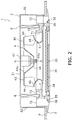
FIG 2 is a schematic cross-sectional side view of the air conditioning apparatus. -
FIG. 3 is an external perspective view of the impeller. -
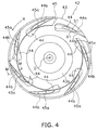
FIG. 4 is a view as indicated by the arrow A inFIG. 3 (excluding part of an end ring). -
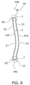
FIG. 5 is a schematic side view of the blade. -
FIG 6 is a cross-sectional view along the line B-B inFIG. 5 . -
FIG 7 is a cross-sectional view along the line C-C inFIG. 5 . -
FIG 8 is a view as indicated by the arrow D inFIG. 5 . -
FIG. 9 is a view as indicated by the arrow E inFIG. 5 . -
FIG. 10 is an enlarged view of the area F inFIG 6 . -
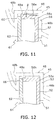
FIG. 11 is a cross-sectional view along the line G-G inFIG. 5 . -
FIG. 12 is an enlarged view of the area H inFIG. 6 . -
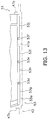
FIG. 13 is a view as indicated by the arrow J inFIG. 8 (showing only the vicinity of the end of a blade body on the side near an end plate). -
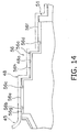
FIG 14 is a view as indicated by the arrow K inFIG. 9 (showing only the vicinity of the end of the blade body on the side near the end ring). -
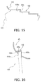
FIG. 15 is a cross-sectional view along the line L-L inFIG. 4 (showing only the end ring). -
FIG. 16 is a cross-sectional view along the line M-M inFIG. 4 (showing only the end ring). -
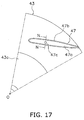
FIG 17 is a partial plan view of the end plate. -
FIG. 18 is a cross-sectional view along the line N-N inFIG 17 . -
FIG. 19 includes drawings showing the steps of fixing the blade to the end plate and the end ring by laser welding, wherein (a) shows the state in which the blade is disposed at a specific position between the end ring and the end plate in the axial direction, (b) shows the state in which a load is applied to the end ring and the end plate, and (c) shows the state in which the blade is laser welded to the end ring and the end plate. -
FIG. 20 shows the state in which a first blade weld part moves in the axial direction when a pressure load is applied to the end plate in a case in which the gap between one part of the first blade weld surface and the plate weld surface is larger than the gaps between the other first blade weld surfaces and the plate weld surface; wherein (a) shows the state in which the blade is disposed at a specific position in the end plate, and (b) shows the state in which a load is applied to the end plate. -
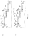
FIG. 21 shows the state in which a second blade weld part moves in the axial direction when a pressure load is applied to the end ring, wherein (a) shows the state in which the blade is disposed at a specific position in the end ring, and (b) shows the state in which the load is applied to the end ring. -
FIG. 22 is a view showing an example in which first slits are formed in the first blade weld parts instead of the first grooves, and is a drawing equivalent toFIG. 13 . -
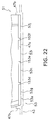
FIG. 23 is a view showing an example in which second slits are formed in the second blade weld parts instead of the second grooves, and is a drawing equivalent toFIG. 14 . -
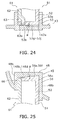
FIG. 24 is a view showing an end plate and a first blade weld part according to a modification, and is a drawing equivalent toFIG. 10 (the end plate is indicated by solid lines). -
FIG. 25 is a view showing an end ring and a second blade weld part according to a modification, and is a drawing equivalent toFIG. 11 (the end ring is indicated by solid lines). -
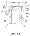
FIG. 26 is a view showing an end ring and a second blade weld part according to a modification, and is a drawing equivalent toFIG. 12 (the end ring is indicated by solid lines). -
- 42
- impeller (impeller for a centrifugal blower)
- 43
- end plate (blade-supporting rotator)
- 44
- blade
- 45
- end ring (blade-supporting rotator)
- 47
- plate weld part (rotator weld part)
- 47a, 147a
- plate weld surface (rotator weld surface)
- 48
- ring weld part (rotator weld part)
- 48a, 148b, 148d
- ring weld surface (rotator weld surface)
- 51
- blade body (first blade surface part)
- 53
- first blade weld part
- 53d, 53e, 53f
- first groove
- 53g, 53h, 53i, 5 3j
- first blade weld surface
- 56
- second blade weld part
- 56b, 56c, 56d
- second groove
- 56e, 56f
- second blade weld surface
- 56g, 56h
- second blade flat surface
- 61
- blade cover (second blade surface part)
- 148a, 148c
- ring flat surface (rotator flat surface)
- 153d, 153e, 153f
- first slit
- 156b, 156c, 156d
- second slit
- The following is a description, made with reference to the drawings, of an embodiment of an impeller blade for a centrifugal blower, a blade-supporting rotator, an impeller for a centrifugal blower, and a method for manufacturing an impeller for a centrifugal blower according to the present invention.
-
FIG. 1 shows an external perspective view of anair conditioning apparatus 1 comprising a centrifugal blower that uses a blade, a blade-supporting rotator, and an impeller for a centrifugal blower according to one embodiment of the present invention (the ceiling is omitted). Theair conditioning apparatus 1 is a ceiling-embedded air conditioning apparatus, and comprises acasing 2 for accommodating various structural devices in its interior, and aface panel 3 disposed on the underside of thecasing 2. Specifically, thecasing 2 of theair conditioning apparatus 1 is disposed by being inserted into an opening formed in a ceiling U of an air-conditioned room, as shown inFIG. 2 (a schematic cross-sectional side view of the air conditioning apparatus 1). Theface panel 3 is disposed so as to fit into the opening in the ceiling U. - In a plan view, the
casing 2 is shaped as a box in which the bottom surface of the substantially octagonal in the plan view is open, the long sides and short sides thereof being formed alternately. The casing has a substantially octagonaltop plate 21 in which long sides and short sides are formed alternately, andside plates 22 extending downward from the peripheral edges of thetop plate 21. - The
face panel 3 is a substantially square plate-shaped member in a plan view, and has anintake port 31 in the substantial center for drawing in air in the air-conditioned room, and a plurality (four in the present embodiment) ofdischarge ports 32 formed so as to correspond to the four sides for blowing air out of the casing into the air-conditioned room. The sides of theface panel 3 are disposed so as to correspond to the long sides of thetop plate 21 of thecasing 2. Theintake port 31 is a substantially square-shaped opening in the present embodiment. The fourdischarge ports 32 are substantially rectangular openings extending in an elongated manner along the respective sides of theface panel 3. Theintake port 31 is provided with anintake grill 33, and afilter 34 for removing dust in the air drawn in through theintake port 31. Thedischarge ports 32 are each provided withhorizontal flaps 35 capable of swinging around a longitudinal axis, making it possible to change the direction of the flow of air blown out through thedischarge ports 32 into the air-conditioned room. - Disposed inside the
casing 2 are primarily ablower 4 for drawing air in the air-conditioned room into thecasing 2 through theintake port 31 of theface panel 3 and blowing the air peripherally outward, and aheat exchanger 6 disposed so as to enclose the external periphery of theblower 4. - In the present embodiment, the
blower 4 is a turbofan as one example of a centrifugal blower, and theblower 4 has afan motor 41 provided in the center of thetop plate 21 of thecasing 2, and an impeller 42 (an impeller for a centrifugal blower) linked to and rotatably driven by ashaft 41a (rotating shaft) of thefan motor 41. The detailed structure of theimpeller 42 is described hereinafter. - In the present embodiment, the
heat exchanger 6 is a cross-fin tube type heat exchange panel that is bent and formed so as to enclose the external periphery of theblower 4, and is connected via a refrigerant pipe to an outdoor unit (not shown) installed outside of the room or another such location. Theheat exchanger 6 is designed to be capable of functioning as an evaporator during the cooling operation and as a condenser during the heating operation. Theheat exchanger 6 is thereby capable of performing heat exchange with the air drawn into thecasing 2 through theintake port 31 by theblower 4, of cooling the air during the cooling operation, and of heating the air during the heating operation. - Disposed beneath the
heat exchanger 6 is adrain pan 7 for receiving drain water produced by the moisture in the air condensing in theheat exchanger 6. Thedrain pan 7 is installed at the bottom of thecasing 2. Thedrain pan 7 has anintake hole 71 formed so as to communicate with theintake port 31 of theface panel 3, discharge holes 72 formed so as to correspond with thedischarge ports 32 of theface panel 3, and a drainwater receiving groove 73 formed beneath theheat exchanger 6 for receiving drain water. - Disposed in the
intake hole 71 of thedrain pan 7 is abell mouth 5 for guiding air taken in through theintake port 31 to theimpeller 42 of theblower 4. - As described above, an air flow channel is formed in the
air conditioning apparatus 1, starting from theintake port 31 of theface panel 3, running through thefilter 34, thebell mouth 5, thedrain pan 7, theblower 4, and theheat exchanger 6, and ending at the fourdischarge ports 32. Air in the air-conditioned room is drawn in and made to exchange heat in theheat exchanger 6, and the air can then be blown out into the air-conditioned room. - Next, the general structure of the
impeller 42 will be described usingFIGS. 2 ,3 , and4 .FIG. 3 is an external perspective view of theimpeller 42.FIG. 4 is a view as indicated by the arrow A inFIG. 3 (excluding part of an end ring 45). - The
impeller 42 primarily has adiscoid end plate 43 as a blade-supporting rotator linked to theshaft 41a of thefan motor 41, a plurality (seven in the present embodiment) ofblades 44 centered around theshaft 41a and arranged annularly on the side of theend plate 43 opposite thefan motor 41, and anannular end ring 45 as a blade-supporting rotator disposed so as to sandwich theblades 44 with theend plate 43 in the axial direction. The center axis line of theshaft 41 a (i.e., the rotational axis line of the impeller 42) is indicated by O-O, and the rotational direction of theimpeller 42 is indicated by R. - Next, the general structure of the
end plate 43 and theend ring 45 as blade-supporting rotators will be described. - The
end plate 43 is a substantially discoid resinous member formed so that a substantially conicalconvex part 43a in the center protrudes toward theintake port 31. - The
end ring 45 is an annular bell-shaped resinous member in which areas farther away from the external periphery and closer to the opening in the central part protrude closer toward theintake port 31. - Next, the
blades 44 will be described usingFIGS. 3 through 14 .FIG. 5 is a schematic side view of theblade 44.FIG. 6 is a cross-sectional view along the line B-B inFIG. 5 .FIG. 7 is a cross-sectional view along the line C-C inFIG 5 .FIG. 8 is a view as indicated by the arrow D inFIG. 5 .FIG. 9 is a view as indicated by the arrow E inFIG. 5 .FIG. 10 is an enlarged view of the area F inFIG. 6 .FIG. 11 is a cross-sectional view along the line G-G inFIG. 5 .FIG. 12 is an enlarged view of the area H inFIG. 6 .FIG. 13 is a view as indicated by the arrow J inFIG. 8 (showing only the vicinity of the end of ablade body 51 on the side near the end plate 43).FIG. 14 is a view as indicated by the arrow K inFIG. 9 (showing only the vicinity of the end of theblade body 51 on the side near the end ring 45). - In the present embodiment, the
blades 44 are resinous members molded separately from theend plate 43 and theend ring 45. One end of each of theblades 44 is fixed to theend plate 43, and the other end is fixed to theend ring 45. In a plan view of theimpeller 42 in the present embodiment, each of theblades 44 has a wing shape inclined farther backward at theend part 44a near theend plate 43 than at theend part 44b near theend ring 45. Each of theblades 44 is also formed so that theseend parts impeller 42. Specifically, each of theblades 44 has a shape that extends axially while twisting between theend plate 43 and theend ring 45. Each of theblades 44 also has a shape in which, in a plan view of theimpeller 42, the axially center portion of theblade 44 protrudes farther radially outward than both theend part 44a near theend plate 43 and theend part 44b near theend ring 45, and theblade 44 has a rounded wing shape when viewed along the chord of the wing. The reason for shaping theblades 44 to twist in the axial direction and for giving the blades a complex rounded shape is to improve the blowing performance and noise quality of theblower 4. - In the present embodiment, in the end facing the R direction in each of these blades 44 (hereinafter referred to as front edge part) are formed front
edge corner parts 44c protruding in a staircase pattern (two steps in the present embodiment) toward the inner periphery of theimpeller 42. The frontedge corner parts 44c have the function of preventing air flow from separating from the negative-pressure surfaces 44f of theblades 44 when the air flow is drawn into theimpeller 42 through theintake port 31 and thebell mouth 5 is blown out toward the outward periphery by theblades 44, thus contributing to reducing the noise of theblower 4. The term "negative-pressure surfaces 44f" refers to the surfaces of theblades 44 that face the inner periphery of theimpeller 42, and the surfaces on the opposite sides of the negative-pressure surfaces 44f, i.e., the surfaces of theblades 44 facing the outer periphery of theimpeller 42, are referred to as positive-pressure surfaces 44e. - In the present embodiment, a plurality of wave-shaped
rear edge projections 44d is formed in the ends of theblades 44 on the sides opposite the R direction (these ends are hereinafter referred to as rear edges), the projections facing toward the external periphery of theimpeller 42. A plurality ofrear edge projections 44d have the function of reducing the pressure differences in the boundaries between the positive-pressure surfaces 44e and negative-pressure surfaces 44f in the rear edges of theblades 44 when air flow drawn into theimpeller 42 through theintake port 31 andbell mouth 5 is blown out toward the outward periphery by theblades 44, thus contributing to reducing the noise of theblower 4. The shapes and numbers of the frontedge corner parts 44c and therear edge projections 44d are not limited to the shapes and numbers in the present embodiment. In cases in which the desired noise quality can be achieved without providing frontedge corner parts 44c orrear edge projections 44d such as those described above, the front edges and rear edges of theblades 44 do not need to be provided with the frontedge corner parts 44c orrear edge projections 44d. - Next, the detailed structure of the
blades 44 will be described. In the present embodiment, theblades 44 are hollow blades, each included the blade body 51 (first blade surface part) fixed to theend plate 43 and theend ring 45, and a blade cover 61 (second blade surface part) forming a hollow space S with theblade body 51, the blade cover being mounted by fitting into theblade body 51. - In the present embodiment, each of the
blade bodies 51 is primarily plate-shaped member constituting the positive-pressure surface 44e and part of the negative-pressure surface 44f (specifically, the rear edge of the negative-pressure surface 44f) of theblade 44. In the present embodiment, each of the blade covers 61 is primarily plate-shaped member constituting part of the negative-pressure surface 44f (specifically, the portion of the negative-pressure surface 44f excluding the rear edge). - Each of the
blade bodies 51 is configured from a positive-pressure surface part 52 constituting the positive-pressure surface 44e of theblade 44, a firstblade weld part 53 as a rotator weld part formed on the side of the positive-pressure surface part 52 near theend plate 43, a rear edge-side edge part 54 formed on the rear edge side of the positive-pressure surface part 52, a front edge-side edge part 55 formed on the front edge side of the positive-pressure surface part 52, and a secondblade weld part 56 as a rotator weld part formed on the side of the positive-pressure surface part 52 near theend ring 45. - Each of the positive-
pressure surface parts 52 has in the substantial center thereof a plurality (three in the present embodiment) ofannular projections 52a protruding toward theblade cover 61. - Each of the first
blade weld parts 53 is a portion welded to theend plate 43 by laser welding, the first blade weld part having primarily a first blade-weldingbody 53a extending from the end of the positive-pressure surface part 52 near the end plate toward theblade cover 61, and anengaging hole 53b, apositioning hole 53c, andfirst grooves body 53a. - The engaging
hole 53b is a long hole disposed along the negative-pressure surface 44f in the substantial center of the direction (specifically, the chord direction) running from the front edge to the rear edge (or from the rear edge to the front edge) of the first blade-weldingbody 53a. - The
positioning hole 53c is a circular hole disposed toward the front edge of theengaging hole 53b. - The
first grooves pressure surface part 52 near theend plate 43 toward theblade cover 61, and a plurality of these grooves (three in the present embodiment, in the order of thefirst groove 53d, thefirst groove 53e, and thefirst groove 53f progressing from the front edge toward the rear edge) is disposed at intervals in a chordal direction. Thefirst grooves blade weld part 53 has a shape partitioned by thesefirst grooves first grooves body 53a near theend plate 43. - First blade weld surfaces 53g, 53h, 53i, 53j as rotator weld surfaces are formed on the first
blade weld part 53 on the surface near theend plate 43. The first blade weld surfaces 53g, 53h, 53i, 53j correspond to the plurality (four in the present embodiment) of portions of the firstblade weld part 53 partitioned by thefirst grooves blade weld surface 53g is the surface of the front edge portion of thefirst groove 53d on the side near theend plate 43, the firstblade weld surface 53h is the surface of the portion between thefirst groove 53d and thefirst groove 53e in the chordal direction on the side near theend plate 43, the firstblade weld surface 53i is the surface of the portion between thefirst groove 53e and thefirst groove 53f in the chordal direction on the side near theend plate 43, and the firstblade weld surface 53j is the surface of the rear edge portion of thefirst groove 53f on the side near theend plate 43. The first blade weld surfaces 53g, 53h, 53i, 53j are inclined with respect to a plane orthogonal to the rotational axis line O-O of theimpeller 42, in a state in which the firstblade weld part 53 is disposed to face aplate weld surface 47a (described later) of the end plate 43 (only the firstblade weld surface 53i is shown inFIG 10 ) in the axial direction. In the present embodiment, each of the first blade weld surfaces 53g, 53h, 53i, 53j is inclined so that areas of this surface farther away from the end of the positive-pressure surface part 52 toward theend plate 43 and closer to a plate-side edge part 63 (described later) protrudes closer to theend plate 43 in the axial direction. The angle of inclination α of the first blade weld surfaces 53g, 53h, 53i, 53j with respect to a plane orthogonal to the rotational axis line O-O of theimpeller 42 is from 0.5 degrees to 2.5 degrees, in a state in which the firstblade weld part 53 is disposed to face theplate weld surface 47a (described later) of theend plate 43 in the axial direction. - The rear edge-
side edge part 54 constitutes the rear edge part of the positive-pressure surface 44e and the rear edge part of the negative-pressure surface 44f of each of theblades 44, and has the plurality ofrear edge projections 44d described above, and a rear edge-side contact part 54a formed in the front edges of therear edge projections 44d and pressed against a rear edge-side edge part 64 (described later) of theblade cover 61. - The front edge-
side edge part 55 constitutes the portion of the frontedge corner parts 44c near the positive-pressure surface part 52, and has a first front edge-side contact part 55a formed in the rear edges of the frontedge corner parts 44c and pressed against a front edge-side edge part 65 (described later) of theblade cover 61. - Each of the second
blade weld parts 56 is a portion welded to theend ring 45 by laser welding, and primarily has a secondblade weld body 56a extending from the end of the positive-pressure surface part 52 near theend ring 45 toward theblade cover 61, andsecond grooves blade weld body 56a is directed from the front edge toward the rear edge of each of theblades 44, and is shaped so as to form an end face in which the distance from the end face near theend plate 43 decreases in a staircase pattern (three steps in the present embodiment). Thesecond grooves pressure surface part 52 near theend ring 45 toward theblade cover 61, and a plurality of these grooves (three in the present embodiment, in the order of thesecond groove 56b, thesecond groove 56c, and thesecond groove 56d from the front edge toward the rear edge) is disposed at intervals in the chordal direction. Thesecond grooves blade weld body 56a, and thesecond groove 56d is disposed in the rearmost portion of the secondblade weld body 56a. Thus, the secondblade weld part 56 has a shape partitioned by thesesecond grooves second grooves blade weld body 56a near theend ring 45. - Second blade weld surfaces 56e, 56f and second blade
flat surfaces blade weld part 56 near theend ring 45. The second blade weld surfaces 56e, 56f correspond to the plurality (four in the present embodiment) of portions of the secondblade weld part 56 partitioned by thesecond grooves blade weld surface 56e is the surface near theend ring 45 between thesecond groove 56b and thesecond groove 56c in the chordal direction, and the secondblade weld surface 56f is the surface of the rear edge-side portion of thesecond groove 56d near theend ring 45. The second bladeflat surface 56g is the surface of the front edge-side portion of thesecond groove 56b near theend ring 45, and the second bladeflat surface 56h is the surface near theend ring 45 of the portion between thesecond groove 56c and thesecond groove 56d in the chordal direction. The second blade weld surfaces 56e, 56f are inclined with respect to a plane orthogonal to the rotational axis line O-O of theimpeller 42, in a state in which the secondblade weld part 56 is disposed to face aring weld surface 48a (described later) of the end ring 45 (only the secondblade weld surface 56e is shown inFIG. 11 ) in the axial direction. In the present embodiment, the second blade weld surfaces 56e, 56f are inclined so as to protrude to the side of theend ring 45 in the axial direction as the second blade weld surfaces are oriented to a ring-side edge part 66 (described later) from the end of the positive-pressure surface part 52 near theend ring 45. The angle of inclination β of the second blade weld surfaces 56e, 56f with respect to a plane orthogonal to the rotational axis line O-O of theimpeller 42 is from 0.5 degrees to 2.5 degrees, in a state in which the secondblade weld part 56 is disposed to face thering weld surface 48a (described later) of theend ring 45 in the axial direction. The second bladeflat surfaces impeller 42, in a state in which the secondblade weld part 56 is disposed to face thering weld surface 48a (described later) of the end ring 45 (only the second bladeflat surface 56h is shown inFIG. 12 ) in the axial direction. Unlike the second blade weld surfaces 56e, 56f, the second bladeflat surfaces end ring 45. - Each of the blade covers 61 includes a negative-
pressure surface part 62 constituting part of the negative-pressure surface 44f of the blade 44 (in the present embodiment, the portion of the negative-pressure surface 44f excluding the rear edge part), a plate-side edge part 63 formed on the side of the negative-pressure surface part 62 near theend plate 43, a rear edge-side edge part 64 formed on the rear edge side of the negative-pressure surface part 62, a front edge-side edge part 65 formed on the front edge side of the negative-pressure surface part 62, and a ring-side edge part 66 formed on the side of the negative-pressure surface part 62 near theend ring 45. - Each of the negative-
pressure surface parts 62 has, at a position corresponding to theannular projections 52a formed in the positive-pressure surface part 52 of theblade body 51, a plurality (three in the present embodiment) offitting projections 62a which protrude toward theblade body 51. Thesefitting projections 62a fit with each of the central concave parts of the correspondingannular projections 52a, and are inserted either until the surface of the negative-pressure surface part 62 near theblade body 51 comes into contact with the ends of theannular projections 52a near theblade cover 61, or until the surface of the positive-pressure surface part 52 near theblade cover 61 comes into contact with the ends of thefitting projections 62a near theblade body 51. - The plate-
side edge part 63 has a shape that follows the end face of the first blade-weldingbody 53a and is in contact with the end face of the first blade-weldingbody 53a near theend ring 45. An engagingpawl 63a that extends from the side near theend ring 45 toward theend plate 43 is formed in the end of the plate-side edge part 63 near theend plate 43, and this pawl is designed to be inserted into the engaginghole 53b. The engagingpawl 63a is formed so that when the pawl is inserted into the engaginghole 53b, the pawl does not protrude from the end face of the first blade-weldingbody 53a near the end plate 43 (specifically, the first blade weld surfaces 53h, 53i) in the axial direction toward theend plate 43, including cases in which a pressure load is applied to theblade 44 during the laser welding steps described hereinafter. Theend part 44a fixed to theend plate 43 is configured by the firstblade weld part 53 of theblade body 51 and the plate-side edge part 63 of theblade cover 61. - The rear edge-
side edge part 64 has a shape that follows along the rear edge-side edge part 54 and is in contact with the end face of the rear edge-side contact part 54a near theblade cover 61. - The front edge-
side edge part 65 constitutes the portion of the frontedge corner parts 44c near the negative-pressure surface part 62 and is in contact with the end face of the first front edge-side contact part 55a on the side near theblade cover 61. - The ring-
side edge part 66 has a shape that follows along the stepped end face of the secondblade weld body 56a and is in contact with the end face of the secondblade weld body 56a on the side near theblade cover 61. The end face of the ring-side edge part 66 near theend ring 45 is formed so as not to protrude from the end face of the secondblade weld body 56a near theend ring 45 in the axial direction toward theend ring 45, including cases in which a pressure load is applied to theblade 44 during the laser welding steps described hereinafter. Theend part 44b fixed to theend ring 45 is configured by the secondblade weld part 56 of theblade body 51 and the ring-side edge part 66 of theblade cover 61. - The
blade 44 is assembled by inserting the engagingpawl 63a of theblade cover 61 into the engaginghole 53b of theblade body 51, and then fitting thefitting projections 62a of theblade cover 61 into the central concave parts of theannular projections 52a of theblade body 51. A hollow space S is thereby formed between theblade body 51 and theblade cover 61. Since theblade body 51 and theblade cover 61 are molded separately, there are few restrictions on the draft direction of the mold used during molding, and the space S can be easily increased even in cases of a rounded, complex wing shape which twists axially, as is the case in the present embodiment. This facilitates making theblade 44 hollow and makes it possible to reduce the weight of theimpeller 42. - Next, the detailed structure of the
end plate 43 and theend ring 45, particularly the positioning structure of theblades 44, will be described usingFIGS. 8 through 18 .FIG. 15 is a cross-sectional view along the line L-L inFIG. 4 (showing only the vicinity of the end ring 45).FIG. 16 is a cross-sectional view along the line M-M inFIG. 4 (showing only the vicinity of the end ring 45).FIG. 17 is a partial plan view of theend plate 43.FIG. 18 is a cross-sectional view along the line N-N inFIG. 17 . - First, the
end ring 45 will be described. When theblades 44 are fixed to theend ring 45, a plurality ofblades 44 must be disposed at specific fixed positions. In theimpeller 42 of the present embodiment, formed in theend ring 45 arering weld parts 48 as rotator weld parts that can be fitted with theend parts 44b of theblades 44 on the sides near the end ring 45 (specifically, the secondblade weld parts 56 of theblade bodies 51 and the ring-side edge parts 66 of the blade covers 61), making it possible to position theblades 44. - Formed in each
ring weld part 48 are aring weld surface 48a (rotating body weld surface) that is disposed to face the stepped end faces of theend parts 44b formed on the surfaces near theend plate 43 in the axial direction, and a bladefitting part 48b extending from the peripheral edge of thering weld surface 48a along theend parts 44b in the axial direction toward theend plate 43. In the present embodiment, the ring weld surfaces 48a are parallel to a plane orthogonal to the rotational axis line O-O of theimpeller 42, in a state in which the secondblade weld parts 56 are disposed to face the ring weld surfaces 48a of theend ring 45 in the axial direction. In a state in which theend parts 44b of theblades 44 are fitted with the bladefitting parts 48b, and the secondblade weld parts 56 are disposed to face the ring weld surfaces 48a of theend ring 45 in the axial direction, the second blade weld surfaces 56e, 56f are inclined with respect to a plane orthogonal to the rotational axis line O-O of theimpeller 42, whereby gaps are formed in the axial direction with the ring weld surfaces 48a, excluding the portions of the second blade weld surfaces 56e, 56f of theblades 44 in proximity to the ring weld surfaces 48a. Gaps are also formed in the axial direction between the second bladeflat surfaces - The
end parts 44b of theblades 44 are fitted with the ring weld parts 48 (specifically, with the bladefitting parts 48b), whereby theend parts 44b (specifically, the secondblade weld parts 56 of the blade bodies 51) are disposed to face the ring weld surfaces 48a in the axial direction, and the secondblade weld parts 56 are then laser welded to the ring weld surfaces 48a, whereby theblades 44 are fixed to theend ring 45. The reason that laser welding is used as the method for fixing theblades 44 to theend ring 45 is because it is preferable to use a procedure in which the heat-affected areas during welding are small in width and there is little strain, considering that theblades 44 of the present embodiment are hollow, thin blades, that the blades are shaped to twist in the axial direction, and that the blades have a rounded, complex wing shape. In the welding steps described later, in order to perform laser welding easily from the sides near theend ring 45, the material constituting theend ring 45 is preferably more optically transmissive than the material constituting theblade bodies 51. For example, theend ring 45 can be white or milky white in color, and theblade bodies 51 can be black in color. - Next, the
end plate 43 will be described. When theblades 44 are fixed to theend plate 43, a plurality ofblades 44 must be disposed at specific fixing positions similar to cases in which theblades 44 are fixed to theend ring 45. In theimpeller 42 of the present embodiment, formed in theend plate 43 areplate weld parts 47 as rotator weld parts that can be fitted with theend parts 44a on the sides of theblades 44 near the end plate 43 (specifically, with the firstblade weld parts 53 of theblade bodies 51 and the plate-side edge parts 63 of the blade covers 61), making it possible to position theblades 44. - Formed in the
plate weld part 47 are plate weld surfaces 47a (rotator weld surfaces) disposed to face the end faces of theend parts 44a formed on the surfaces near theend ring 45 in the axial direction, bladefitting parts 47b extending from the peripheral edges of the plate weld surfaces 47a along theend parts 44a in the axial direction toward theend ring 45, andpositioning projections 47c that can be inserted into thepositioning holes 53c formed in theend parts 44a (specifically, the first blade-weldingbodies 53a). In the present embodiment, the plate weld surfaces 47a are parallel to a plane orthogonal to the rotational axis line O-O of theimpeller 42, in a state in which the firstblade weld parts 53 are disposed to face the plate weld surfaces 47a of theend plate 43 in the axial direction. In a state in which theend parts 44a of theblades 44 are fitted with the bladefitting parts 47b, and the firstblade weld parts 53 are disposed to face the plate weld surfaces 47a of theend plate 43 in the axial direction, the first blade weld surfaces 53g, 53h, 53i, 53j are inclined with respect to a plane orthogonal to the rotational axis line O-O of theimpeller 42, whereby gaps are formed in the axial direction with the plate weld surfaces 47a, excluding the portions of the first blade weld surfaces 53g, 53h, 53i, 53j of theblades 44 in proximity to the plate weld surfaces 47a. - The
end parts 44a of theblades 44 are fitted with the plate weld parts 47 (specifically, with the bladefitting parts 47b), whereby theend parts 44a (specifically, the firstblade weld parts 53 of the blade bodies 51) are disposed to face the plate weld surfaces 47a in the axial direction, and the firstblade weld parts 53 are then laser welded to the plate weld surfaces 47a, whereby theblades 44 are fixed to theend plate 43. The reason that laser welding is used as the method for fixing theblades 44 to theend plate 43 is because it is preferable to use a procedure in which the heat-affected areas during welding are small in width and there is little strain, considering that theblades 44 of the present embodiment are hollow, thin blades, that the blades are shaped to twist in the axial direction, and that the blades have a rounded, complex wing shape. In the welding steps described later, in order to perform laser welding easily from the sides near theend plate 43, the material constituting theend plate 43 is preferably more optically transmissive than the material constituting theblade bodies 51. For example, theend plate 43 can be white or milky white in color, and theblade bodies 51 can be black in color. - Next, the method for manufacturing the
impeller 42 will be described usingFIGS. 5 through 21 .FIG. 19 includes drawings showing the steps of fixing ablade 44 to theend plate 43 and theend ring 45 by laser welding, wherein (a) shows the state in which theblade 44 is disposed at a specific position between theend ring 45 and theend plate 43 in the axial direction, (b) shows the state in which a load is applied to theend ring 45 and theend plate 43, and (c) shows the state in which theblade 44 is laser welded to theend ring 45 and theend plate 43.FIG. 20 shows the state in which a firstblade weld part 53 moves in the axial direction when a pressure load is applied to theend plate 43 in a case in which the gap between a part of firstblade weld surface 53h and theplate weld surface 47a is larger than the gaps between the other first blade weld surfaces 53g, 53i, 53j and theplate weld surface 47a; wherein (a) shows the state in which theblade 44 is disposed at a specific position in theend plate 43, and (b) shows the state in which a load is applied to theend plate 43.FIG. 21 shows the state in which a secondblade weld part 56 moves in the axial direction when a pressure load is applied to theend ring 45, wherein (a) shows the state in which ablade 44 is disposed at a specific position in theend ring 45, and (b) shows the state in which the load is applied to theend ring 45. - First, the
blade bodies 51, the blade covers 61, theend plate 43, and theend ring 45 are molded from a resin and prepared for use. - Next, the blade covers 61 are attached by being fitted into the
blade bodies 51 to assemble theblades 44. Specifically, the engagingpawls 63a of the blade covers 61 are inserted into the engagingholes 53b, and thefitting projections 62a of the blade covers 61 are then fitted into theannular projections 52a of theblade bodies 51 to assemble theblades 44. - Next, the
end parts 44b of theblades 44 near theend ring 45 are fitted with thering weld parts 48 of theend ring 45, and theend parts 44a of theblades 44 are fitted with theplate weld parts 47 of theend plate 43, whereby a plurality ofblades 44 are disposed at specific positions between theend ring 45 and theend plate 43 in the axial direction. This results in a state in which the firstblade weld parts 53 are disposed to face the plate weld surfaces 47a in the axial direction, and the secondblade weld parts 56 are disposed to face the ring weld surfaces 48a in the axial direction. At this time, since the first blade weld surfaces 53g, 53h, 53i, 53j are inclined with respect to the plate weld surfaces 47a, and the second blade weld surfaces 56e, 56f are inclined with respect to the ring weld surfaces 48a, gaps are formed in the axial direction with the plate weld surfaces 47a (seeFIGS. 10 through 14 andFIG. 19(a) ), excluding the portions of the first blade weld surfaces 53g, 53h, 53i, 53j of theblades 44 in proximity to the plate weld surfaces 47a (the portions near the blade covers 61 in this case). - Next, a pressure load is applied to the
end plate 43 and theend ring 45, so as to cause theblades 44 to be compressed in the axial direction by theend plate 43 and theend ring 45. At this time, in theend parts 44a of theblades 44 near theend plate 43, the pressure load concentrates in the portions of the first blade weld surfaces 53g, 53h, 53i, 53j near the blade covers 61, whereby the first blade weld surfaces 53g, 53h, 53i, 53j are pressed in the axial direction toward theend ring 45 by the plate weld surfaces 47a, and substantially the entire first blade weld surfaces 53g, 53h, 53i, 53j are firmly adhered along the plate weld surfaces 47a accordingly (seeFIG. 19(b) ). In theend parts 44b of theblades 44 near theend ring 45, the pressure load concentrates in the portion of the second blade weld surfaces 56e, 56f near the blade covers 61, similar to theend parts 44a, whereby the second blade weld surfaces 56e, 56f are pressed in the axial direction toward theend plate 43 by the ring weld surfaces 48a, and substantially the entire second blade weld surfaces 56e, 56f are firmly adhered along the ring weld surfaces 48a accordingly. - Depending on the finishing precision during the resin molding of the
blades 44 and theend plate 43, there are cases in which unevenness occur in the first blade weld surfaces 53g, 53h, 53i, 53j and the plate weld surfaces 47a, and the gaps between each of the first blade weld surfaces 53g, 53h, 53i, 53j and the plate weld surfaces 47a may sometimes occur unevenness in the weld surfaces 53g, 53h, 53i, 53j, 47a. For example, in a state in which ablade 44 is disposed at a specific position in theend plate 43 as shown inFIG. 20(a) , a case is considered in which, among the gaps between the first blade weld surfaces 53g, 53h, 53i, 53j and theplate weld surface 47a in the axial direction, the gap between the firstblade weld surface 53h and theplate weld surface 47a is larger than the gaps between the other first blade weld surfaces 53g, 53i, 53j and theplate weld surface 47a. In such a case, when the pressure load is applied to theend plate 43, the portions of the first blade weld surfaces 53g, 53i, 53j near the blade covers 61 are pressed in the axial direction toward theend ring 45 as shown inFIG. 20(b) . At this time, since thefirst grooves blade weld surface 53h is not pressed in the axial direction toward theend ring 45, thefirst grooves blade weld surface 53h in the chordal direction deform in accordance with the distance by which the first blade weld surfaces 53g, 53i move in the axial direction. When the distance by which the first blade weld surfaces 53g, 53i move in the axial direction has increased to a certain point, the firstblade weld surface 53h comes into contact with theplate weld surface 47a, and substantially the entire first blade weld surfaces 53g, 53h, 53i, 53j are firmly adhered to theplate weld surface 47a. Thus, substantially the entire first blade weld surfaces 53g, 53h, 53i, 53j are firmly adhered to theplate weld surface 47a by thefirst grooves plate weld surface 47a, and there is less chance that there will be portions where the gaps between the weld surfaces cannot be reduced. - Concerning the axial movement of the second blade weld surfaces 56e, 56f of the second
blade weld parts 56, in a state in which ablade 44 is disposed at a specific position in theend ring 45 as shown inFIG. 21(a) , the second bladeflat surfaces ring weld surface 48a, are disposed at positions axially farther away from thering weld surface 48a than the portions of the second blade weld surfaces 56e, 56f in proximity to thering weld surface 48a. Therefore, when a pressure load is applied to theend ring 45 in this state, the portions of the second blade weld surfaces 56e, 56f near theblade cover 61 are pressed in the axial direction toward theend plate 43, as shown inFIG. 21(b) . Therefore, when a pressure load is applied to theend ring 45 as shown inFIG. 21(b) , only the portions of the secondblade weld part 56 that correspond to the second blade weld surfaces 56e, 56f are moved axially by the pressure load, thesecond grooves flat surfaces ring weld surface 48a than the second bladeflat surfaces end ring 45 can therefore be further reduced. - Next, in a state in which a pressure load is applied to the
end plate 43 and theend ring 45 so as to compress theblades 44 in the axial direction, laser light is irradiated at the first blade weld parts 53 (more specifically, at the four locations of the first blade weld surfaces 53g, 53h, 53i, 53j) from the surface of theend plate 43 on the opposite side of theblades 44 in the axial direction, and theblades 44 are fixed to the plate weld surfaces 47a by welding. Laser light is also irradiated at the second blade weld parts 56 (more specifically, at the two locations of the second blade weld surfaces 56e, 56f) from the surface of theend ring 45 on the opposite side of the blades in the axial direction, and theblades 44 are fixed to the ring weld surfaces 48a by welding. At this time, the desired welding strength can be achieved in a stable manner because the adherence between the first blade weld surfaces 53g, 53h, 53i, 53j and the plate weld surfaces 47a are satisfactory, and the adherence between the second blade weld surfaces 56e, 56f and the ring weld surfaces 48a are satisfactory. - The
blades 44 constituting theblower 4 of the present embodiment are resinous hollow blades having hollow spaces formed in interiors thereof, and the first blade weld surfaces 53g, 53h, 53i, 53j inclined (angle of inclination α, seeFIG. 10 ) with respect to the plate weld surfaces 47a are formed in the firstblade weld parts 53 in a state in which the firstblade weld parts 53 are disposed to face the plate weld surfaces 47a as rotator weld surfaces (seeFIG 19(a) ) in the axial direction. The second blade weld surfaces 56e, 56f inclined (angle of inclination β, seeFIG. 11 ) with respect to the ring weld surfaces 48a are formed in the secondblade weld parts 56 in a state in which theblades 44 are disposed so that the secondblade weld parts 56 face the ring weld surfaces 48a as rotator weld surfaces (seeFIG. 19(a) ) in the axial direction. - With
such blades 44, when a load is applied so as to press theend plate 43 and theblades 44 each other in the axial direction as theblades 44 are fixed by laser welding to theend plate 43, the portions in proximity to the plate weld surfaces 47a formed by the inclining of the first blade weld surfaces 53g, 53h, 53i, 53j (the portions near the blade covers 61 in this case) are firmly pressed into the plate weld surfaces 47a in a state in which the firstblade weld parts 53 are disposed to face the plate weld surfaces 47a in the axial direction. As a result, the adherence between the first blade weld surfaces 53g, 53h, 53i, 53j and the plate weld surfaces 47a is satisfactory, and theblades 44 can therefore be fixed to theend plate 43 with high welding strength. With theseblades 44, when a load is applied so as to press theend ring 45 and theblades 44 each other in the axial direction as theblades 44 are fixed by laser welding to theend ring 45, the portions in proximity to the ring weld surfaces 48a formed by the inclining of the second blade weld surfaces 56e, 56f (the portions near the blade covers 61 in this case) are firmly pressed into the ring weld surfaces 48a in a state in which the secondblade weld parts 56 are disposed to face the ring weld surfaces 48a in the axial direction. As a result, the adherence between the second blade weld surfaces 56e, 56f and thering weld surfaces 48a is satisfactory, and theblades 44 can therefore be fixed to theend ring 45 with high welding strength. - With these
blades 44, it is thereby possible to achieve satisfactory adherence between the first blade weld surfaces 53g, 53h, 53i, 53j of theblades 44 and the plate weld surfaces 47a of theend plate 43, or satisfactory adherence between the second blade weld surfaces 56e, 56f of theblades 44 and the ring weld surfaces 48a of theend ring 45; and to achieve welding strength in a stable manner, even in cases in which unevenness are formed in each of the weld surfaces due to the finishing precision during resin molding of theblades 44, theend plate 43, and theend ring 45. In cases in which theblades 44 are given a complex rounded shape in order to improve blowing performance or noise quality (seeFIGS. 4 and19 ), or in cases in which theblades 44 are thinned in order to reduce the weight of theimpeller 42, when the pressure load such as is described above is applied, the load compressing theblades 44 in the axial direction is applied, causing theblades 44 to bend, and there is a danger that the gaps will increase between the first blade weld surfaces 53g, 53h, 53i, 53j of theblades 44 and the plate weld surfaces 47a of theend plate 43, or that the gaps will increase between the second blade weld surfaces 56e, 56f of theblades 44 and the ring weld surfaces 48a of theend ring 45. However, with theblades 44, the pressure load can be concentrated in the portions in proximity to the plate weld surfaces 47a formed by the inclining of the first blade weld surfaces 53g, 53h, 53i, 53j (the portions near the blade covers 61 in this case), or in the portions in proximity to the ring weld surfaces 48a formed by the inclining of the second blade weld surfaces 56e, 56f (the portions near the blade covers 61 in this case). Therefore, the pressure load applied between theblades 44 and theend plate 43 orend ring 45 can be reduced in comparison with cases in which an attempt is made to firmly adhere the entire un-inclined blade weld surfaces to the entire plate weld surfaces of the end plate. There is thereby less danger that the gaps will increase between the first blade weld surfaces 53g, 53h, 53i, 53j of theblades 44 and the plate weld surfaces 47a of theend plate 43. It is also possible to achieve satisfactory adherence between the first blade weld surfaces 53g, 53h, 53i, 53j of theblades 44 and the plate weld surfaces 47a of theend plate 43, or between the second blade weld surfaces 56e, 56f of theblades 44 and the ring weld surfaces 48a of theend ring 45, and the desired welding strength can be achieved in a stable manner. - Thus, the
impeller 42 of the present embodiment is manufactured by forming the first blade weld surfaces 53g, 53h, 53i, 53j inclined with respect to the plate weld surfaces 47a in a state in which the firstblade weld parts 53 are disposed to face the plate weld surfaces 47a of theend plate 43 in the axial direction, and also in a state in which the secondblade weld parts 56 are disposed to face the ring weld surfaces 48a of theend ring 45 in the axial direction; and by fixing theblades 44, on which are formed the second blade weld surfaces 56e, 56f inclined with respect to the ring weld surfaces 48a, by laser welding to theend plate 43 and theend ring 45, in a state in which the load is applied so as to press theend plate 43 and theblades 44 each other in the axial direction, and also in a state in which the load is applied so as to press theend ring 45 and theblades 44 each other in the axial direction. The blades are therefore fixed to the blade-supporting rotator with high welding strength. Therefore, when theblades 44 are fixed by laser welding to theend plate 43 or theend ring 45, the pressure load applied between theblades 44 and theend plate 43 orend ring 45 in the axial direction can be reduced, the length of the laser welded portions can be reduced, theblades 44 can be given a complex rounded shape in order to improve blowing performance and noise quality, theblades 44 can be thinned in order to reduce the weight of theimpeller 42, and, as a result, costs can be reduced. - With the
blades 44 constituting theblower 4 of the present embodiment, since the angle of inclination α of the first blade weld surfaces 53g, 53h, 53i, 53j with respect to the plate weld surfaces 47a is 0.5 degrees or more, and the angle of inclination β of the second blade weld surfaces 56e, 56f with respect to thering weld surfaces 48a is 0.5 degrees or greater, the gaps that may form between the first blade weld surfaces of the blades and the plate weld surfaces of the end plate can be reduced by applying the pressure load between theend plate 43 and theblades 44 in the axial direction or between theend ring 45 and theblades 44 in the axial direction, and the operation for firmly adherence the weld surfaces together can be reliably achieved. Moreover, since the angle of inclination α of the first blade weld surfaces 53g, 53h, 53i, 53j with respect to the plate weld surfaces 47a is 2.5 degrees or less, and the angle of inclination β of the second blade weld surfaces 56e, 56f with respect to thering weld surfaces 48a is 2.5 degrees or less, it is possible to reduce the gaps that may form between the first blade weld surfaces 53g, 53h, 53i, 53j of theblades 44 and the plate weld surfaces 47a of theend plate 43 or between the second blade weld surfaces 56e, 56f and the ring weld surfaces 48a of theend ring 45 without the orientation of theblades 44 being greatly changed by the angles of inclination, and the operation for firmly adherence the weld surfaces together can be reliably achieved. - Thus, with the
blades 44 constituting theblower 4 of the present embodiment, it is possible to achieve an operation for reducing the gaps that may form in the axial direction between the first blade weld surfaces 53g, 53h, 53i, 53j of theblades 44 and the plate weld surfaces 47a of theend plate 43 or between the second blade weld surfaces 56e, 56f and the ring weld surfaces 48a of theend ring 45 in a reliable manner and without the orientation of theblades 44 being greatly changed by the angles of inclination. - With the
blades 44 constituting theblower 4 of the present embodiment, when the pressure load is applied in the axial direction between theblades 44 and theend plate 43 or theend ring 45 as theblades 44 are fixed by laser welding to theend plate 43 orend ring 45, there are sometimes cases in which the axially compressing load is applied to theblades 44, theblades 44 bend, and the axially central portions of theblades 44 protrude orthogonally to the axial direction (to the right of the paper surface inFIG. 19 ), in cases in which, e.g., theblades 44 are given a complex rounded shape (seeFIGS. 4 and19 ). Therefore, the portions of the firstblade weld parts 53 or the secondblade weld parts 56 on the side substantially opposite the side in which the axially central portions of theblades 44 protrude orthogonally to the axial direction (the portions near the blade covers 61 in this case) are thereby inclined in a direction aparting from the axial direction with respect to the plate weld surfaces 47a or the ring weld surfaces 48a, and the gaps between the first blade weld surfaces 53g, 53h, 53i, 53j and the plate weld surfaces 47a or between the second blade weld surfaces 56e, 56f and the ring weld surfaces 48a tend to increase. - However, with the
blades 44 constituting theblower 4 of the present embodiment, the first blade weld surfaces 53g, 53h, 53i, 53j or the second blade weld surfaces 56e, 56f are inclined so as to be closer to the plate weld surfaces 47a or the ring weld surfaces 48a as the blade weld surfaces are oriented in a direction (to the left of the paper surface inFIG. 19 ) substantially opposite a direction (to the right of the paper surface inFIG. 19 ) in which the axially central portions of theblades 44 are protruded orthogonally to the axial direction by the bending of theblades 44. Therefore, it is possible to maintain a state in which the gaps are small between the portions in the first blade weld surfaces 53g, 53h, 53i, 53j or second blade weld surfaces 56e, 56f of theblades 44 on the sides substantially opposite to the sides in which the axially central portions of theblades 44 protrude orthogonally to the axial direction, and the plate weld surfaces 47a of theend plate 43 or the ring weld surfaces 48a of theend ring 45. It is also possible to achieve satisfactory adherence between the first blade weld surfaces 53g, 53h, 53i, 53j of theblades 44 and the plate weld surfaces 47a of theend plate 43, or between the second blade weld surfaces 56e, 56f of theblades 44 and the ring weld surfaces 48a of theend ring 45, and the welding strength can be achieved in a stable manner. - The
blades 44 constituting theblower 4 of the present embodiment are configured by attaching the blade covers 61 to theblade bodies 51, wherein the firstblade weld parts 53 are formed so as to extend from the ends of theblade bodies 51 near theend plate 43 toward the blade covers 61, and the secondblade weld parts 56 are formed so as to extend from the ends of theblade bodies 51 near theend ring 45 toward the blade covers 61. Therefore, when the pressure load is applied in the axial direction between theblades 44 and theend plate 43 orend ring 45 as theblades 44 are fixed by laser welding to theend plate 43 orend ring 45, the portions of the firstblade weld parts 53 near the blade covers 61, which are less rigid than the portions near theblade bodies 51, are inclined in the axial direction away from the plate weld surfaces 47a, and the gaps between the first blade weld surfaces 53g, 53h, 53i, 53j and the plate weld surfaces 47a tend to increase. The aforementioned portions of the first blade weld parts are also inclined in the axial direction away from the ring weld surfaces 48a, and the gaps between the second blade weld surfaces 56e, 56f and the ring weld surfaces 48a tend to increase. - However, with the
blades 44, since the first blade weld surfaces 53g, 53h, 53i, 53j are inclined so as to be closer to the plate weld surfaces 47a as the first blade weld surfaces are oriented toward the blade covers 61, it is possible to maintain a state in which the gaps are small between the portions of the first blade weld surfaces 53g, 53h, 53i, 53j of theblades 44 near the blade covers 61 and the plate weld surfaces 47a of theend plate 43. It is also possible to achieve satisfactory adherence between the first blade weld surfaces 53g, 53h, 53i, 53j of theblades 44 and the plate weld surfaces 47a of theend plate 43, and the desired welding strength can be achieved in a stable manner. On the side near theend ring 45, since the second blade weld surfaces 56e, 56f are inclined so as to be closer to the ring weld surfaces 48a as the second blade weld surfaces are oriented toward the blade covers 61, it is possible to maintain a state in which the gaps are small between the portions of the second blade weld surfaces 56e, 56f of theblades 44 near the blade covers 61 and the ring weld surfaces 48a of theend ring 45. It is also possible to achieve satisfactory adherence between the second blade weld surfaces 56e, 56f of theblades 44 and the ring weld surfaces 48a of theend ring 45, and the welding strength can be achieved in a stable manner. - With the
blades 44 constituting theblower 4 of the present embodiment, in cases in which unevenness occur in each of the weld surfaces due to the finishing precision during resin molding of theblades 44, theend plate 43, and theend ring 45, merely providing an incline to the first blade weld surfaces 53g, 53h, 53i, 53j or the second blade weld surfaces 56e, 56f gives rise to the danger that there will still be portions in which it is impossible to reduce the gaps between the first blade weld surfaces 53g, 53h, 53i, 53j of theblades 44 and the plate weld surfaces 47a of theend plate 43, or between the second blade weld surfaces 56e, 56f of theblades 44 and the ring weld surfaces 48a of theend ring 45. However, with theblades 44,first grooves blade weld parts 53, andsecond grooves blade weld parts 56, whereby the parts of the firstblade weld parts 53 and the parts of the secondblade weld parts 56 partitioned by these grooves are able to move as separate portions in the axial direction, with the grooves acting as boundaries (seeFIGS. 20 and21 ). Therefore, it is possible to reduce the danger that there will still be portions in which it is impossible to reduce the gaps between the first blade weld surfaces 53g, 53h, 53i, 53j of theblades 44 and the plate weld surfaces 47a of theend plate 43, or between the second blade weld surfaces 56e, 56f and the ring weld surfaces 48a of theend ring 45. It is also possible to achieve satisfactory adherence between the first blade weld surfaces 53g, 53h, 53i, 53j of theblades 44 and the plate weld surfaces 47a of theend plate 43 and between the second blade weld surfaces 56e, 56f of theblades 44 and the ring weld surfaces 48a of theend ring 45, and the welding strength can be achieved in a stable manner. - In cases in which the
blades 44 are made to bend by the pressure load in the axial direction between theblades 44 and theend plate 43 orend ring 45 as theblades 44 are fixed by laser welding to theend plate 43 orend ring 45, such as cases in which theblades 44 are given a complex rounded shape in order to improve blowing performance or noise quality, or cases in which theblades 44 are thinned in order to reduce the weight of the impeller, there may be portions in which the gaps increase between first blade weld surfaces 53g, 53h, 53i, 53j of theblades 44 and the plate weld surfaces 47a of theend plate 43 or between the second blade weld surfaces 56e, 56f of theblades 44 and the ring weld surfaces 48a of theend ring 45. Therefore, merely providing an incline to the first blade weld surfaces 53g, 53h, 53i, 53j or the second blade weld surfaces 56e, 56f gives rise to the danger that there will still be portions in which it is impossible to reduce the gaps between the first blade weld surfaces 53g, 53h, 53i, 53j of theblades 44 and the plate weld surfaces 47a of theend plate 43, or between the second blade weld surfaces 56e, 56f of theblades 44 and the ring weld surfaces 48a of theend ring 45. However, in this case, as with the case described above,first grooves blade weld parts 53, andsecond grooves blade weld parts 56, whereby the parts of the firstblade weld parts 53 and the parts of the secondblade weld parts 56 partitioned by these grooves are able to move as separate portions in the axial direction, with the grooves acting as boundaries (seeFIGS. 20 and21 ). Therefore, even in cases in which theblades 44 are made to bend by the pressure load in the axial direction between theblades 44 and theend plate 43 orend ring 45, it is possible to reduce the danger that there will still be portions in which it is impossible to reduce the gaps between the first blade weld surfaces 53g, 53h, 53i, 53j of theblades 44 and the plate weld surfaces 47a of theend plate 43, or between the second blade weld surfaces 56e, 56f and the ring weld surfaces 48a of theend ring 45. It is also possible to achieve satisfactory adherence between the first blade weld surfaces 53g, 53h, 53i, 53j of theblades 44 and the plate weld surfaces 47a of theend plate 43 and between the second blade weld surfaces 56e, 56f of theblades 44 and the ring weld surfaces 48a of theend ring 45, and the welding strength can be achieved in a stable manner. - Thus, with the
blades 44 of the present embodiment, not only are inclines provided to the first blade weld surfaces 53g, 53h, 53i, 53j and the second blade weld surfaces 56e, 56f, but alsofirst grooves second grooves - With the
blades 44 constituting theblower 4 of the present embodiment, second bladeflat surfaces blade weld parts 56 so as to be adjacent to the second blade weld surfaces 56e, 56f in a state in which the secondblade weld parts 56 are disposed to face the ring weld surfaces 48a in the axial direction, and thesecond grooves flat surfaces blade weld parts 56 partitioned by thesecond grooves flat surfaces second grooves FIG. 21 ). When the pressure load is applied between theend ring 45 and theblades 44, the pressure load can be reliably concentrated in the portions of the second blade weld surfaces 56e, 56f closer to the ring weld surfaces 48a than the second bladeflat surfaces blade weld parts 56 corresponding to the second blade weld surfaces 56e, 56f are moved axially by the pressure load, and the portions corresponding to the second bladeflat surfaces blades 44 are fixed by laser welding to theend ring 45, the pressure load applied between theend ring 45 and theblades 44 can be further reduced. - In the present embodiment,
first grooves blade weld parts 53, andsecond grooves blade weld parts 56 in order to allow the firstblade weld parts 53 and the secondblade weld parts 56 to move axially as described above, but, instead of these grooves,first slits blade weld parts 53, andsecond slits blade weld parts 56, as shown inFIGS. 22 and23 . It is possible to allow the firstblade weld parts 53 and the secondblade weld parts 56 to move axially as described above in this case as well. - In the embodiment described above, in order to improve the adherence between the weld surfaces when the first
blade weld parts 53 or secondblade weld parts 56 of theblades 44 are laser welded to the plate weld surfaces 47a of theend plate 43 or the ring weld surfaces 48a of theend ring 45, the first blade weld surfaces 53g, 53h, 53i, 53j of the firstblade weld parts 53 are inclined with respect to the plate weld surfaces 47a, and the second blade weld surfaces 56e, 56f of the secondblade weld parts 56 are inclined with respect to the ring weld surfaces 48a (seeFIGS. 10 through 12 ). However, another option is to incline the plate weld surfaces of theend plate 43 with respect to the first blade weld surfaces 53g, 53h, 53i, 53j of the firstblade weld parts 53, and to incline the ring weld surfaces of theend ring 45 with respect to the second blade weld surfaces 56e, 56f of the secondblade weld parts 56, as shown inFIGS. 24 through 26 . -
FIG. 24 is a view showing a modification in which aplate weld surface 147a of anend plate 43 is inclined with respect to first blade weld surfaces 53g, 53h, 53i, 53j of a firstblade weld part 53. This case presents a state in which the firstblade weld part 53 is disposed to face theplate weld surface 147a in the axial direction, wherein the first blade weld surfaces 53g, 53h, 53i, 53j of the firstblade weld part 53 are made to be parallel to a plane orthogonal to the rotational axis line O-O of theimpeller 42, and theplate weld surface 147a is inclined so as to be closer to the first blade weld surfaces 53g, 53h, 53i, 53j as the plate weld surface is oriented toward theblade cover 61. In this case as well, the portions of the first blade weld surfaces 53g, 53h, 53i, 53j in proximity to theplate weld surface 147a (the portions near theblade cover 61 in this case) are firmly pressed into theplate weld surface 147a. As a result, satisfactory adherence can be achieved between the first blade weld surfaces 53g, 53h, 53i, 53j and theplate weld surface 147a, and theblade 44 can therefore be fixed to theend plate 43 with high welding strength. The angle range in the embodiment described above can be applied for this angle of inclination α as well. Furthermore, as in the embodiment described above, formingfirst grooves FIG. 13 ) orfirst slits FIG. 22 ) in the firstblade weld part 53 makes it possible to achieve the same effects as in the embodiment described above in which the first grooves or first slits are formed. -
FIGS. 25 and26 are drawings showing a modification in which aring weld surface 48a of anend ring 45 is inclined with respect to second blade weld surfaces 56e, 56f of a secondblade weld part 56. This case presents a state in which the secondblade weld part 56 is disposed to face the ring weld surface in the axial direction, wherein the second blade weld surfaces 56e, 56f and second bladeflat surfaces blade weld part 56 are made to be parallel to a plane orthogonal to the rotational axis line O-O of theimpeller 42, and ring weld surfaces 148b, 148d are inclined so as to be closer to the second blade weld surfaces 56e, 56f as the ring weld surfaces approach theblade cover 61. The ring weld surfaces 148b, 148d are disposed at positions that are opposite the second blade weld surfaces 56e, 56f in the axial direction, and ringflat surfaces flat surfaces FIG. 26 ). In this case as well, the portions of the second blade weld surfaces 56e, 56f in proximity to the ring weld surfaces 148b, 148d (the portions near theblade cover 61 in this case) are firmly pressed into the ring weld surfaces 148b, 148d. As a result, satisfactory adherence is achieved between the second blade weld surfaces 56e, 56f and the ring weld surfaces 148b, 148d, and theblade 44 can therefore be fixed to theend ring 45 with high welding strength. The angle range in the embodiment described above can be applied for this angle of inclination β as well. Furthermore, as in the embodiment described above, formingsecond grooves FIG. 14 ) orsecond slits FIG. 23 ) in the secondblade weld part 56 makes it possible to achieve the same effects as in the embodiment described above in which the second grooves or second slits are formed. - In an impeller for a centrifugal blower configured by using laser welding to fix resinous blades having hollow spaces formed in interiors thereof to a resinous blade-supporting rotator, using the present invention makes it possible to achieve satisfactory adherence between the weld surface of the blade and the weld surface of the blade-supporting rotator, and the welding strength can be achieved in a stable manner,.
Claims (15)
- An impeller blade (44) for a centrifugal blower in which a plurality of blades are arranged annularly around a rotational axis of a resinous blade-supporting rotator, the blades being fixed by laser welding to rotator weld surfaces formed on one side surface in the axial direction of the blade-supporting rotator; whereinthe impeller blade is a resinous hollow blade having blade weld part (53, 56) welded to the rotator weld surface at one end, a hollow space being formed in the blade interior; andcharacterised in thata blade weld surface (53g, 53h, 53i, 53j, 56e, 56f) inclined with respect to the rotator weld surface is formed in the blade weld part in a state in which the blade weld part is disposed to face the rotator weld surface in the axial direction.
- The impeller blade (44) for a centrifugal blower as recited in claim 1, wherein the blade weld surface (53g, 53h, 53i, 53j, 56e, 56f) is configured to be inclined at an angle of 0.5 degrees to 2.5 degrees with respect to the rotator weld surface.
- The impeller blade (44) for a centrifugal blower as recited in claim 1 or 2, wherein the blade weld surface (53g, 53h, 53i, 53j, 56e, 56f) is inclined so as to be closer to the rotator weld surface as the blade weld surface is oriented in a direction substantially opposite a direction in which an axially central portion of the blade protrudes orthogonally in the axial direction by bending the blade during application of an axially compressing load.
- The impeller blade (44) for a centrifugal blower as recited in any of claims 1 through 3, whereinthe impeller blade includes a first blade surface part (51), and a second blade surface part (61) attached to the first blade surface part to form the hollow space with the first blade surface part;the blade weld part (53, 56) is formed so as to extend from the blade-supporting rotator side end of the first blade surface part toward the second blade surface part; andthe blade weld surface (53g, 53h, 53i, 53j, 56e, 56f) is configured to be inclined so as to be closer to the rotator weld surface as the blade weld surface is oriented toward the second blade surface part.
- The impeller blade (44) for a centrifugal blower as recited in any of claims 1 through 4, wherein a groove (53d, 53e, 53f, 56b, 56c, 56d) or slit (153d, 153e, 153f, 156b, 156c, 156d) is formed in the blade weld part (53, 56).
- The impeller blade (44) for a centrifugal blower as recited in any of claims 1 through 4, wherein blade flat surface (56g, 56h) configured to be parallel to the rotator weld surface and disposed at position axially farther away from the rotator weld surface than the portion of the blade weld surface (56e, 56f) in proximity to the rotator weld surface, is formed in the blade weld part (56) in addition to the blade weld surface so as to be adjacent to the blade weld surface in a state in which the blade weld part is disposed to face the rotator weld surface in the axial direction, and a groove (56b, 56c, 56d) or slit (156b, 156c, 156d) is formed so as to correspond to a boundary between the blade weld surface and the blade flat surface.
- An impeller (42) for a centrifugal blower, comprising:a blade-supporting rotator (43, 45), which is a resinous member that rotate around a rotational axis and include rotator weld parts (47, 48) having a rotator weld surface (47a, 48a) formed on one side surface in the axial direction; anda plurality of impeller blades (44) for a centrifugal blower as recited in any of claims 1 through 6 configured to be disposed annularly around the axis of the blade-supporting rotator and configured to be fixed by laser welding to the rotator weld surfaces.
- Blade-supporting rotator (43, 45) of an impeller for a centrifugal blower in which a plurality of resinous blades are disposed on one axial side, the blades being disposed annularly around a rotational axis and having hollow spaces in the blade interiors, and blade weld surfaces formed at one ends of the blades are fixed by laser welding to the blade-supporting rotator; wherein:the blade-supporting rotator is a member having rotator weld parts (47, 48) welded to the blade weld surfaces in the blade side surface in the axial direction and configured to rotate around a rotational axis; androtator weld surfaces (147a, 148b, 148d) inclined with respect to the blade weld surfaces are formed in the rotator weld parts in a state in which the rotator weld parts are disposed to face the blade weld surfaces in the axial direction.
- The blade-supporting rotator (43, 45) of an impeller for a centrifugal blower as recited in Claim 8, wherein the rotator weld surfaces (147a, 148b, 148d) are configured to be inclined at an angle of 0.5 degrees to 2.5 degrees with respect to the blade weld surfaces.
- The blade-supporting rotator (43, 45) of an impeller for a centrifugal blower as recited in Claim 8 or 9, wherein the rotator weld surfaces (147a, 148b, 148d) are configured to be inclined so as to be closer to the blade weld surfaces as the rotator weld surfaces are oriented in a direction substantially opposite a direction in which axially central portions of the blades protrude orthogonally in the axial direction by bending the blades during application of an axially compressing load.
- An impeller (42) for a centrifugal blower, comprising:a plurality of resinous impeller blades (44), which are hollow blades disposed annularly around a rotational axis and having hollow spaces in the blade interiors, and which have blade weld parts (53, 56) having blade weld surfaces (53g, 53h, 53i, 53j, 56e, 56f) formed at one ends; andblade-supporting rotator (43, 45) of an impeller for a centrifugal blower as recited in any of Claims 8 through 10, the rotator being disposed on the blade weld part sides of the blades, and the blade weld surfaces being fixed to the rotator by laser welding.
- The impeller (42) for a centrifugal blower as recited in Claim 11, whereinthe blades (44) include first blade surface parts (51), and second blade surface parts (61) attached to the first blade surface parts to form the hollow spaces with the first blade surface parts;the blade weld parts (53, 56) are formed so as to extend from the blade-supporting rotator side ends of the first blade surface parts toward the second blade surface parts; andthe rotator weld surfaces (147a, 148b, 148d) are inclined so as to be closer to the blade weld surfaces (53g, 53h, 53i, 53j, 56e, 56f) as the rotator weld surfaces are oriented toward the second blade surface parts.
- The impeller for a centrifugal blower as recited in Claim 11 or 12, wherein a groove (53d, 53e, 53f, 56b, 56c, 56d) or slit (153d, 153e, 153f, 156b, 156c, 156d) is formed in each of the blade weld parts (53, 56).
- The impeller (42) for a centrifugal blower as recited in Claim 11 or 12, wherein:a rotator flat surface (148a, 148c) is formed in each of the rotator weld parts (48) in addition to the rotator weld surface (148b, 148d) so as to be adjacent to the rotator weld surface in a state in which the rotator weld parts are disposed to face the blade weld surfaces (56e, 56f) in the axial direction, the rotator flat surfaces being parallel to the blade weld surfaces and being disposed at positions axially farther away from the blade weld surfaces than the portions of the rotator weld surfaces in proximity to the blade weld surfaces; anda groove (56b, 56c, 56d) or slit (156b, 156c, 156d) is formed in each of the blade weld parts so as to correspond to a boundary between the rotator weld surfaces and the rotator flat surfaces.
- A method for manufacturing an impeller for a centrifugal blower comprising resinous blade-supporting rotator which rotate around a rotational axis, and a plurality of resinous blades disposed annularly around the axis and having hollow spaces formed in the blade interiors; whereinthe blade-supporting rotator (43, 45) has rotator weld parts (47, 48) including rotator weld surfaces (47a, 48a, 147a, 148b, 148d) formed on one side surface in the axial direction;the blades (44) have blade weld parts (53, 56) on which are formed blade weld surfaces (53g, 53h, 53i, 53j, 56e, 56f) inclined with respect to the rotator weld surfaces in a state in which the blade-supporting rotator side ends are disposed to face the rotator weld surfaces in the axial direction; andthe blade weld parts are disposed to face the rotator weld surfaces in the axial direction, and the blades are fixed to the rotator weld surfaces by laser welding.
Applications Claiming Priority (2)
| Application Number | Priority Date | Filing Date | Title |
|---|---|---|---|
| JP2006062095A JP3953085B1 (en) | 2006-03-08 | 2006-03-08 | Centrifugal blower impeller blade, blade support rotating body, centrifugal blower impeller, and method for manufacturing centrifugal blower impeller |
| PCT/JP2007/054235 WO2007102476A1 (en) | 2006-03-08 | 2007-03-06 | Blade of impeller for centrifugal fan, rotating body for supporting blades, impeller for centrifugal fan, and method of producing impeller for centrifugal fan |
Publications (3)
| Publication Number | Publication Date |
|---|---|
| EP1995466A1 EP1995466A1 (en) | 2008-11-26 |
| EP1995466A4 EP1995466A4 (en) | 2015-03-11 |
| EP1995466B1 true EP1995466B1 (en) | 2016-05-11 |
Family
ID=38456413
Family Applications (1)
| Application Number | Title | Priority Date | Filing Date |
|---|---|---|---|
| EP07737810.7A Not-in-force EP1995466B1 (en) | 2006-03-08 | 2007-03-06 | Blade of impeller for centrifugal fan, rotating body for supporting blades, impeller for centrifugal fan, and method of producing impeller for centrifugal fan |
Country Status (5)
| Country | Link |
|---|---|
| US (2) | US20090047133A1 (en) |
| EP (1) | EP1995466B1 (en) |
| JP (1) | JP3953085B1 (en) |
| CN (1) | CN101395382B (en) |
| WO (1) | WO2007102476A1 (en) |
Cited By (1)
| Publication number | Priority date | Publication date | Assignee | Title |
|---|---|---|---|---|
| US11566634B2 (en) | 2018-10-31 | 2023-01-31 | Carrier Corporation | Arrangement of centrifugal impeller of a fan for reducing noise |
Families Citing this family (26)
| Publication number | Priority date | Publication date | Assignee | Title |
|---|---|---|---|---|
| JPWO2009139422A1 (en) * | 2008-05-14 | 2011-09-22 | ダイキン工業株式会社 | Centrifugal blower |
| IT1397327B1 (en) * | 2009-12-11 | 2013-01-10 | Nuovo Pignone Spa | METHODS AND SYSTEMS FOR RADIUS WELDING. |
| JP5287772B2 (en) * | 2010-03-16 | 2013-09-11 | 株式会社デンソー | Centrifugal multi-blade fan |
| US8556584B2 (en) * | 2011-02-03 | 2013-10-15 | General Electric Company | Rotating component of a turbine engine |
| JP6078945B2 (en) * | 2011-11-04 | 2017-02-15 | ダイキン工業株式会社 | Centrifugal blower |
| JP5988776B2 (en) * | 2012-08-29 | 2016-09-07 | 三菱電機株式会社 | Centrifugal blower and air conditioner equipped with this centrifugal blower |
| JP6161940B2 (en) * | 2013-04-12 | 2017-07-12 | 日清紡メカトロニクス株式会社 | Turbofan and turbofan manufacturing method |
| KR20140125522A (en) * | 2013-04-19 | 2014-10-29 | 엘지전자 주식회사 | turbo fan |
| JP6341637B2 (en) * | 2013-06-14 | 2018-06-13 | 三菱電機株式会社 | Manufacturing method of centrifugal blower |
| US9651057B2 (en) * | 2013-12-19 | 2017-05-16 | Regal Beloit America, Inc. | Blower assembly including a noise attenuating impeller and method for assembling the same |
| CN104948498A (en) * | 2014-03-27 | 2015-09-30 | 美的集团武汉制冷设备有限公司 | Centrifugation wind wheel and manufacturing method thereof |
| JP2016084743A (en) * | 2014-10-24 | 2016-05-19 | 日清紡メカトロニクス株式会社 | Turbo fan and manufacturing method of turbo fan |
| US10400605B2 (en) * | 2014-10-30 | 2019-09-03 | Mitsubishi Electric Corporation | Turbofan and indoor unit for air conditioning apparatus |
| JP6561485B2 (en) * | 2015-02-13 | 2019-08-21 | スズキ株式会社 | Cooling fan structure for internal combustion engine |
| JP6486458B2 (en) * | 2015-04-20 | 2019-03-20 | 三菱電機株式会社 | Turbo fan and air conditioner |
| PL415045A1 (en) | 2015-12-03 | 2017-06-05 | General Electric Company | Turbine disk and methods for manufacturing them |
| BR112018011912B1 (en) * | 2015-12-28 | 2022-11-29 | Daikin Industries, Ltd | METHOD AND APPARATUS FOR MANUFACTURING AN IMPELLER OF A CENTRIFUGAL FAN |
| JP6282720B2 (en) * | 2016-12-27 | 2018-02-21 | ミネベアミツミ株式会社 | Centrifugal fan |
| CN107127960B (en) * | 2017-05-09 | 2023-07-07 | 四川朗迪塑胶电器有限公司 | Multistation fan flabellum shaping device |
| WO2018220808A1 (en) * | 2017-06-02 | 2018-12-06 | 三菱電機株式会社 | Centrifugal fan, air conditioner, and centrifugal fan manufacturing method |
| CN108131324A (en) * | 2018-01-15 | 2018-06-08 | 汕头大学 | A kind of small-sized multi-wing centrifugal exhaust fan of highly effective low noise and impeller |
| KR102069575B1 (en) | 2018-02-08 | 2020-01-23 | 엘지전자 주식회사 | A Manufacturing Method for Impeller |
| JP6673385B2 (en) * | 2018-02-22 | 2020-03-25 | ダイキン工業株式会社 | Turbo fan and air conditioner indoor unit |
| KR20210115303A (en) * | 2020-03-12 | 2021-09-27 | 엘지전자 주식회사 | Impeller |
| EP4166791A1 (en) * | 2021-10-15 | 2023-04-19 | Nicotra Gebhardt GmbH | Radial fan |
| AU2022433486A1 (en) * | 2022-01-17 | 2024-05-02 | Mitsubishi Electric Corporation | Impeller, centrifugal blower, and indoor unit |
Family Cites Families (17)
| Publication number | Priority date | Publication date | Assignee | Title |
|---|---|---|---|---|
| US2916199A (en) * | 1958-04-07 | 1959-12-08 | Westinghouse Electric Corp | Centrifugal fan wheels |
| US3144204A (en) * | 1962-08-24 | 1964-08-11 | Acme Engineering And Mfg Corp | Centrifugal blower wheel |
| US3536416A (en) * | 1968-05-14 | 1970-10-27 | Dov Z Glucksman | Squirrel-cage rotor for fluid moving devices |
| US3694881A (en) * | 1970-06-10 | 1972-10-03 | Dov Z Glucksman | Method for manufacturing squirrel-cage rotors for fluid moving devices |
| JPS5045445A (en) * | 1973-08-29 | 1975-04-23 | ||
| US3856434A (en) * | 1973-10-18 | 1974-12-24 | Westinghouse Electric Corp | Centrifugal fan wheel |
| US4874293A (en) * | 1988-11-08 | 1989-10-17 | Gutzwiller H Leslie | Modified centrifugal airfoil fan wheel |
| FR2700130B1 (en) * | 1993-01-06 | 1995-02-03 | Snecma | Method for manufacturing a one-piece hollow blade rotor and one-piece hollow blade rotor. |
| US6712593B2 (en) * | 2000-11-02 | 2004-03-30 | Kioritz Corporation | Combination of split bodies for use in assembling blower fan by hollow article molding process |
| SE519781C2 (en) * | 2001-08-29 | 2003-04-08 | Volvo Aero Corp | Process for producing a stator or rotor component |
| FR2846898B1 (en) * | 2002-11-07 | 2005-07-15 | Snecma Moteurs | METHOD FOR LASER WELDING IN ONE PASS OF A T-ASSEMBLY OF METAL PARTS |
| US7122761B2 (en) * | 2002-11-12 | 2006-10-17 | Siemens Power Generation, Inc. | Friction processing weld preparation |
| JP4432474B2 (en) * | 2003-11-27 | 2010-03-17 | ダイキン工業株式会社 | Centrifugal blower impeller and centrifugal blower provided with the impeller |
| US7370787B2 (en) * | 2003-12-15 | 2008-05-13 | Pratt & Whitney Canada Corp. | Compressor rotor and method for making |
| US7476080B2 (en) * | 2004-07-26 | 2009-01-13 | Yutaka Giken Co., Ltd. | Impeller for fluid transmitting device and method of manufacturing the same |
| CN101395376B (en) * | 2006-03-03 | 2011-04-06 | 大金工业株式会社 | Compressor and manufacturing method thereof |
| JP5061836B2 (en) * | 2007-10-10 | 2012-10-31 | 株式会社日立プラントテクノロジー | Impeller welding method and impeller |
-
2006
- 2006-03-08 JP JP2006062095A patent/JP3953085B1/en not_active Expired - Fee Related
-
2007
- 2007-03-06 EP EP07737810.7A patent/EP1995466B1/en not_active Not-in-force
- 2007-03-06 CN CN2007800080678A patent/CN101395382B/en not_active Expired - Fee Related
- 2007-03-06 US US12/281,591 patent/US20090047133A1/en not_active Abandoned
- 2007-03-06 WO PCT/JP2007/054235 patent/WO2007102476A1/en active Application Filing
-
2013
- 2013-06-14 US US13/918,442 patent/US8732948B2/en not_active Expired - Fee Related
Cited By (1)
| Publication number | Priority date | Publication date | Assignee | Title |
|---|---|---|---|---|
| US11566634B2 (en) | 2018-10-31 | 2023-01-31 | Carrier Corporation | Arrangement of centrifugal impeller of a fan for reducing noise |
Also Published As
| Publication number | Publication date |
|---|---|
| WO2007102476A1 (en) | 2007-09-13 |
| US20130276303A1 (en) | 2013-10-24 |
| US8732948B2 (en) | 2014-05-27 |
| EP1995466A4 (en) | 2015-03-11 |
| US20090047133A1 (en) | 2009-02-19 |
| EP1995466A1 (en) | 2008-11-26 |
| JP2007239567A (en) | 2007-09-20 |
| CN101395382A (en) | 2009-03-25 |
| CN101395382B (en) | 2011-09-14 |
| JP3953085B1 (en) | 2007-08-01 |
Similar Documents
| Publication | Publication Date | Title |
|---|---|---|
| EP1995466B1 (en) | Blade of impeller for centrifugal fan, rotating body for supporting blades, impeller for centrifugal fan, and method of producing impeller for centrifugal fan | |
| JP4432474B2 (en) | Centrifugal blower impeller and centrifugal blower provided with the impeller | |
| EP3348840A1 (en) | Volute fan assembly structure and floor-standing air conditioner | |
| JP3861008B2 (en) | Turbofan and air conditioner equipped with the same | |
| JP3757802B2 (en) | Turbofan, and blower and air conditioner using turbofan | |
| EP2848817B1 (en) | Centrifugal fan and air-conditioning apparatus | |
| WO2014034359A1 (en) | Centrifugal blower and air conditioner with centrifugal blower | |
| CN105156345A (en) | Volute fan combined structure and vertical air conditioner | |
| US20080134713A1 (en) | Turbo fan and air conditioner having the same | |
| WO2017126444A1 (en) | Centrifugal fan impeller | |
| JP2007040617A (en) | Air conditioning indoor unit | |
| KR20200040569A (en) | Fan for Noise and Vibration Reduction and Air Conditioner with the Same | |
| JP2009250112A (en) | Impeller of centrifugal blower | |
| KR101622400B1 (en) | Outdoor unit of air-conditioner | |
| JP2019135432A (en) | Louver, air conditioner, and assembly method of air conditioner | |
| JP6673385B2 (en) | Turbo fan and air conditioner indoor unit | |
| JP4807225B2 (en) | Outdoor unit for air conditioner | |
| JP2007051790A (en) | Air-conditioning indoor unit | |
| JP3876797B2 (en) | Centrifugal blower | |
| KR100507324B1 (en) | Turbo fan for air-conditioner |
Legal Events
| Date | Code | Title | Description |
|---|---|---|---|
| PUAI | Public reference made under article 153(3) epc to a published international application that has entered the european phase |
Free format text: ORIGINAL CODE: 0009012 |
|
| 17P | Request for examination filed |
Effective date: 20080925 |
|
| AK | Designated contracting states |
Kind code of ref document: A1 Designated state(s): AT BE BG CH CY CZ DE DK EE ES FI FR GB GR HU IE IS IT LI LT LU LV MC MT NL PL PT RO SE SI SK TR |
|
| DAX | Request for extension of the european patent (deleted) | ||
| A4 | Supplementary search report drawn up and despatched |
Effective date: 20150210 |
|
| RIC1 | Information provided on ipc code assigned before grant |
Ipc: F04D 29/30 20060101AFI20150204BHEP Ipc: B29L 31/08 20060101ALI20150204BHEP Ipc: B29C 65/16 20060101ALI20150204BHEP Ipc: F04D 29/28 20060101ALI20150204BHEP Ipc: B21K 3/04 20060101ALI20150204BHEP Ipc: B29C 65/00 20060101ALI20150204BHEP Ipc: F04D 29/02 20060101ALI20150204BHEP Ipc: F04D 29/62 20060101ALI20150204BHEP |
|
| GRAP | Despatch of communication of intention to grant a patent |
Free format text: ORIGINAL CODE: EPIDOSNIGR1 |
|
| RIC1 | Information provided on ipc code assigned before grant |
Ipc: B29L 31/08 20060101ALI20151116BHEP Ipc: F04D 29/62 20060101ALI20151116BHEP Ipc: F04D 29/28 20060101ALI20151116BHEP Ipc: F04D 29/02 20060101ALI20151116BHEP Ipc: F04D 29/30 20060101AFI20151116BHEP Ipc: B21K 3/04 20060101ALI20151116BHEP Ipc: B29C 65/00 20060101ALI20151116BHEP Ipc: B29C 65/16 20060101ALI20151116BHEP |
|
| INTG | Intention to grant announced |
Effective date: 20151216 |
|
| GRAS | Grant fee paid |
Free format text: ORIGINAL CODE: EPIDOSNIGR3 |
|
| GRAA | (expected) grant |
Free format text: ORIGINAL CODE: 0009210 |
|
| AK | Designated contracting states |
Kind code of ref document: B1 Designated state(s): AT BE BG CH CY CZ DE DK EE ES FI FR GB GR HU IE IS IT LI LT LU LV MC MT NL PL PT RO SE SI SK TR |
|
| REG | Reference to a national code |
Ref country code: GB Ref legal event code: FG4D |
|
| REG | Reference to a national code |
Ref country code: CH Ref legal event code: EP |
|
| REG | Reference to a national code |
Ref country code: AT Ref legal event code: REF Ref document number: 798896 Country of ref document: AT Kind code of ref document: T Effective date: 20160515 |
|
| REG | Reference to a national code |
Ref country code: IE Ref legal event code: FG4D |
|
| REG | Reference to a national code |
Ref country code: DE Ref legal event code: R096 Ref document number: 602007046260 Country of ref document: DE |
|
| REG | Reference to a national code |
Ref country code: LT Ref legal event code: MG4D |
|
| REG | Reference to a national code |
Ref country code: NL Ref legal event code: MP Effective date: 20160511 |
|
| PG25 | Lapsed in a contracting state [announced via postgrant information from national office to epo] |
Ref country code: NL Free format text: LAPSE BECAUSE OF FAILURE TO SUBMIT A TRANSLATION OF THE DESCRIPTION OR TO PAY THE FEE WITHIN THE PRESCRIBED TIME-LIMIT Effective date: 20160511 Ref country code: FI Free format text: LAPSE BECAUSE OF FAILURE TO SUBMIT A TRANSLATION OF THE DESCRIPTION OR TO PAY THE FEE WITHIN THE PRESCRIBED TIME-LIMIT Effective date: 20160511 Ref country code: LT Free format text: LAPSE BECAUSE OF FAILURE TO SUBMIT A TRANSLATION OF THE DESCRIPTION OR TO PAY THE FEE WITHIN THE PRESCRIBED TIME-LIMIT Effective date: 20160511 |
|
| REG | Reference to a national code |
Ref country code: AT Ref legal event code: MK05 Ref document number: 798896 Country of ref document: AT Kind code of ref document: T Effective date: 20160511 |
|
| PG25 | Lapsed in a contracting state [announced via postgrant information from national office to epo] |
Ref country code: SE Free format text: LAPSE BECAUSE OF FAILURE TO SUBMIT A TRANSLATION OF THE DESCRIPTION OR TO PAY THE FEE WITHIN THE PRESCRIBED TIME-LIMIT Effective date: 20160511 Ref country code: ES Free format text: LAPSE BECAUSE OF FAILURE TO SUBMIT A TRANSLATION OF THE DESCRIPTION OR TO PAY THE FEE WITHIN THE PRESCRIBED TIME-LIMIT Effective date: 20160511 Ref country code: LV Free format text: LAPSE BECAUSE OF FAILURE TO SUBMIT A TRANSLATION OF THE DESCRIPTION OR TO PAY THE FEE WITHIN THE PRESCRIBED TIME-LIMIT Effective date: 20160511 Ref country code: GR Free format text: LAPSE BECAUSE OF FAILURE TO SUBMIT A TRANSLATION OF THE DESCRIPTION OR TO PAY THE FEE WITHIN THE PRESCRIBED TIME-LIMIT Effective date: 20160812 Ref country code: PT Free format text: LAPSE BECAUSE OF FAILURE TO SUBMIT A TRANSLATION OF THE DESCRIPTION OR TO PAY THE FEE WITHIN THE PRESCRIBED TIME-LIMIT Effective date: 20160912 |
|
| PG25 | Lapsed in a contracting state [announced via postgrant information from national office to epo] |
Ref country code: IT Free format text: LAPSE BECAUSE OF FAILURE TO SUBMIT A TRANSLATION OF THE DESCRIPTION OR TO PAY THE FEE WITHIN THE PRESCRIBED TIME-LIMIT Effective date: 20160511 |
|
| PG25 | Lapsed in a contracting state [announced via postgrant information from national office to epo] |
Ref country code: EE Free format text: LAPSE BECAUSE OF FAILURE TO SUBMIT A TRANSLATION OF THE DESCRIPTION OR TO PAY THE FEE WITHIN THE PRESCRIBED TIME-LIMIT Effective date: 20160511 Ref country code: RO Free format text: LAPSE BECAUSE OF FAILURE TO SUBMIT A TRANSLATION OF THE DESCRIPTION OR TO PAY THE FEE WITHIN THE PRESCRIBED TIME-LIMIT Effective date: 20160511 Ref country code: CZ Free format text: LAPSE BECAUSE OF FAILURE TO SUBMIT A TRANSLATION OF THE DESCRIPTION OR TO PAY THE FEE WITHIN THE PRESCRIBED TIME-LIMIT Effective date: 20160511 Ref country code: DK Free format text: LAPSE BECAUSE OF FAILURE TO SUBMIT A TRANSLATION OF THE DESCRIPTION OR TO PAY THE FEE WITHIN THE PRESCRIBED TIME-LIMIT Effective date: 20160511 Ref country code: SK Free format text: LAPSE BECAUSE OF FAILURE TO SUBMIT A TRANSLATION OF THE DESCRIPTION OR TO PAY THE FEE WITHIN THE PRESCRIBED TIME-LIMIT Effective date: 20160511 |
|
| REG | Reference to a national code |
Ref country code: DE Ref legal event code: R097 Ref document number: 602007046260 Country of ref document: DE |
|
| PG25 | Lapsed in a contracting state [announced via postgrant information from national office to epo] |
Ref country code: BE Free format text: LAPSE BECAUSE OF FAILURE TO SUBMIT A TRANSLATION OF THE DESCRIPTION OR TO PAY THE FEE WITHIN THE PRESCRIBED TIME-LIMIT Effective date: 20160511 Ref country code: AT Free format text: LAPSE BECAUSE OF FAILURE TO SUBMIT A TRANSLATION OF THE DESCRIPTION OR TO PAY THE FEE WITHIN THE PRESCRIBED TIME-LIMIT Effective date: 20160511 Ref country code: PL Free format text: LAPSE BECAUSE OF FAILURE TO SUBMIT A TRANSLATION OF THE DESCRIPTION OR TO PAY THE FEE WITHIN THE PRESCRIBED TIME-LIMIT Effective date: 20160511 |
|
| REG | Reference to a national code |
Ref country code: FR Ref legal event code: PLFP Year of fee payment: 11 |
|
| PLBE | No opposition filed within time limit |
Free format text: ORIGINAL CODE: 0009261 |
|
| STAA | Information on the status of an ep patent application or granted ep patent |
Free format text: STATUS: NO OPPOSITION FILED WITHIN TIME LIMIT |
|
| 26N | No opposition filed |
Effective date: 20170214 |
|
| PG25 | Lapsed in a contracting state [announced via postgrant information from national office to epo] |
Ref country code: SI Free format text: LAPSE BECAUSE OF FAILURE TO SUBMIT A TRANSLATION OF THE DESCRIPTION OR TO PAY THE FEE WITHIN THE PRESCRIBED TIME-LIMIT Effective date: 20160511 |
|
| REG | Reference to a national code |
Ref country code: CH Ref legal event code: PL |
|
| PG25 | Lapsed in a contracting state [announced via postgrant information from national office to epo] |
Ref country code: MC Free format text: LAPSE BECAUSE OF FAILURE TO SUBMIT A TRANSLATION OF THE DESCRIPTION OR TO PAY THE FEE WITHIN THE PRESCRIBED TIME-LIMIT Effective date: 20160511 |
|
| REG | Reference to a national code |
Ref country code: IE Ref legal event code: MM4A |
|
| PG25 | Lapsed in a contracting state [announced via postgrant information from national office to epo] |
Ref country code: LU Free format text: LAPSE BECAUSE OF NON-PAYMENT OF DUE FEES Effective date: 20170306 |
|
| REG | Reference to a national code |
Ref country code: FR Ref legal event code: PLFP Year of fee payment: 12 |
|
| PG25 | Lapsed in a contracting state [announced via postgrant information from national office to epo] |
Ref country code: CH Free format text: LAPSE BECAUSE OF NON-PAYMENT OF DUE FEES Effective date: 20170331 Ref country code: LI Free format text: LAPSE BECAUSE OF NON-PAYMENT OF DUE FEES Effective date: 20170331 Ref country code: IE Free format text: LAPSE BECAUSE OF NON-PAYMENT OF DUE FEES Effective date: 20170306 |
|
| PG25 | Lapsed in a contracting state [announced via postgrant information from national office to epo] |
Ref country code: MT Free format text: LAPSE BECAUSE OF NON-PAYMENT OF DUE FEES Effective date: 20170306 |
|
| PG25 | Lapsed in a contracting state [announced via postgrant information from national office to epo] |
Ref country code: HU Free format text: LAPSE BECAUSE OF FAILURE TO SUBMIT A TRANSLATION OF THE DESCRIPTION OR TO PAY THE FEE WITHIN THE PRESCRIBED TIME-LIMIT; INVALID AB INITIO Effective date: 20070306 |
|
| PG25 | Lapsed in a contracting state [announced via postgrant information from national office to epo] |
Ref country code: BG Free format text: LAPSE BECAUSE OF FAILURE TO SUBMIT A TRANSLATION OF THE DESCRIPTION OR TO PAY THE FEE WITHIN THE PRESCRIBED TIME-LIMIT Effective date: 20160511 |
|
| PG25 | Lapsed in a contracting state [announced via postgrant information from national office to epo] |
Ref country code: CY Free format text: LAPSE BECAUSE OF NON-PAYMENT OF DUE FEES Effective date: 20160511 |
|
| PG25 | Lapsed in a contracting state [announced via postgrant information from national office to epo] |
Ref country code: TR Free format text: LAPSE BECAUSE OF FAILURE TO SUBMIT A TRANSLATION OF THE DESCRIPTION OR TO PAY THE FEE WITHIN THE PRESCRIBED TIME-LIMIT Effective date: 20160511 |
|
| PG25 | Lapsed in a contracting state [announced via postgrant information from national office to epo] |
Ref country code: IS Free format text: LAPSE BECAUSE OF FAILURE TO SUBMIT A TRANSLATION OF THE DESCRIPTION OR TO PAY THE FEE WITHIN THE PRESCRIBED TIME-LIMIT Effective date: 20160911 |
|
| PGFP | Annual fee paid to national office [announced via postgrant information from national office to epo] |
Ref country code: FR Payment date: 20210210 Year of fee payment: 15 |
|
| PGFP | Annual fee paid to national office [announced via postgrant information from national office to epo] |
Ref country code: DE Payment date: 20210224 Year of fee payment: 15 Ref country code: GB Payment date: 20210225 Year of fee payment: 15 |
|
| REG | Reference to a national code |
Ref country code: DE Ref legal event code: R119 Ref document number: 602007046260 Country of ref document: DE |
|
| GBPC | Gb: european patent ceased through non-payment of renewal fee |
Effective date: 20220306 |
|
| PG25 | Lapsed in a contracting state [announced via postgrant information from national office to epo] |
Ref country code: GB Free format text: LAPSE BECAUSE OF NON-PAYMENT OF DUE FEES Effective date: 20220306 Ref country code: FR Free format text: LAPSE BECAUSE OF NON-PAYMENT OF DUE FEES Effective date: 20220331 Ref country code: DE Free format text: LAPSE BECAUSE OF NON-PAYMENT OF DUE FEES Effective date: 20221001 |