EP1995454B1 - Device for the adjustment of the pitch of a rotor blade of a wind turbine - Google Patents
Device for the adjustment of the pitch of a rotor blade of a wind turbine Download PDFInfo
- Publication number
- EP1995454B1 EP1995454B1 EP07010505.1A EP07010505A EP1995454B1 EP 1995454 B1 EP1995454 B1 EP 1995454B1 EP 07010505 A EP07010505 A EP 07010505A EP 1995454 B1 EP1995454 B1 EP 1995454B1
- Authority
- EP
- European Patent Office
- Prior art keywords
- pitch
- bearing shaft
- ring
- bearing
- relatively
- Prior art date
- Legal status (The legal status is an assumption and is not a legal conclusion. Google has not performed a legal analysis and makes no representation as to the accuracy of the status listed.)
- Not-in-force
Links
- 230000007246 mechanism Effects 0.000 description 6
- 208000007101 Muscle Cramp Diseases 0.000 description 5
- 230000006835 compression Effects 0.000 description 2
- 238000007906 compression Methods 0.000 description 2
- 239000012530 fluid Substances 0.000 description 2
- 239000004020 conductor Substances 0.000 description 1
- 238000010276 construction Methods 0.000 description 1
- 239000013013 elastic material Substances 0.000 description 1
- 239000002184 metal Substances 0.000 description 1
- 238000012797 qualification Methods 0.000 description 1
- 230000003068 static effect Effects 0.000 description 1
Images


Classifications
-
- F—MECHANICAL ENGINEERING; LIGHTING; HEATING; WEAPONS; BLASTING
- F03—MACHINES OR ENGINES FOR LIQUIDS; WIND, SPRING, OR WEIGHT MOTORS; PRODUCING MECHANICAL POWER OR A REACTIVE PROPULSIVE THRUST, NOT OTHERWISE PROVIDED FOR
- F03D—WIND MOTORS
- F03D7/00—Controlling wind motors
- F03D7/02—Controlling wind motors the wind motors having rotation axis substantially parallel to the air flow entering the rotor
- F03D7/022—Adjusting aerodynamic properties of the blades
- F03D7/0224—Adjusting blade pitch
-
- F—MECHANICAL ENGINEERING; LIGHTING; HEATING; WEAPONS; BLASTING
- F03—MACHINES OR ENGINES FOR LIQUIDS; WIND, SPRING, OR WEIGHT MOTORS; PRODUCING MECHANICAL POWER OR A REACTIVE PROPULSIVE THRUST, NOT OTHERWISE PROVIDED FOR
- F03D—WIND MOTORS
- F03D15/00—Transmission of mechanical power
- F03D15/10—Transmission of mechanical power using gearing not limited to rotary motion, e.g. with oscillating or reciprocating members
-
- F—MECHANICAL ENGINEERING; LIGHTING; HEATING; WEAPONS; BLASTING
- F03—MACHINES OR ENGINES FOR LIQUIDS; WIND, SPRING, OR WEIGHT MOTORS; PRODUCING MECHANICAL POWER OR A REACTIVE PROPULSIVE THRUST, NOT OTHERWISE PROVIDED FOR
- F03D—WIND MOTORS
- F03D80/00—Details, components or accessories not provided for in groups F03D1/00 - F03D17/00
- F03D80/70—Bearing or lubricating arrangements
-
- F—MECHANICAL ENGINEERING; LIGHTING; HEATING; WEAPONS; BLASTING
- F05—INDEXING SCHEMES RELATING TO ENGINES OR PUMPS IN VARIOUS SUBCLASSES OF CLASSES F01-F04
- F05B—INDEXING SCHEME RELATING TO WIND, SPRING, WEIGHT, INERTIA OR LIKE MOTORS, TO MACHINES OR ENGINES FOR LIQUIDS COVERED BY SUBCLASSES F03B, F03D AND F03G
- F05B2260/00—Function
- F05B2260/70—Adjusting of angle of incidence or attack of rotating blades
- F05B2260/72—Adjusting of angle of incidence or attack of rotating blades by turning around an axis parallel to the rotor centre line
-
- F—MECHANICAL ENGINEERING; LIGHTING; HEATING; WEAPONS; BLASTING
- F05—INDEXING SCHEMES RELATING TO ENGINES OR PUMPS IN VARIOUS SUBCLASSES OF CLASSES F01-F04
- F05B—INDEXING SCHEME RELATING TO WIND, SPRING, WEIGHT, INERTIA OR LIKE MOTORS, TO MACHINES OR ENGINES FOR LIQUIDS COVERED BY SUBCLASSES F03B, F03D AND F03G
- F05B2270/00—Control
- F05B2270/50—Control logic embodiment by
- F05B2270/508—Control logic embodiment by mechanical means, e.g. levers, gears or cams
-
- Y—GENERAL TAGGING OF NEW TECHNOLOGICAL DEVELOPMENTS; GENERAL TAGGING OF CROSS-SECTIONAL TECHNOLOGIES SPANNING OVER SEVERAL SECTIONS OF THE IPC; TECHNICAL SUBJECTS COVERED BY FORMER USPC CROSS-REFERENCE ART COLLECTIONS [XRACs] AND DIGESTS
- Y02—TECHNOLOGIES OR APPLICATIONS FOR MITIGATION OR ADAPTATION AGAINST CLIMATE CHANGE
- Y02E—REDUCTION OF GREENHOUSE GAS [GHG] EMISSIONS, RELATED TO ENERGY GENERATION, TRANSMISSION OR DISTRIBUTION
- Y02E10/00—Energy generation through renewable energy sources
- Y02E10/70—Wind energy
- Y02E10/72—Wind turbines with rotation axis in wind direction
Definitions
- the invention relates to a device for the adjustment of the pitch of a rotor blade of a wind turbine.
- a wind turbine comprises two, three or more rotor blades arranged at a hub.
- a rotor blade is as a rule adjustable relatively to the hub wherein the so called pitch of the rotor blade is adjusted. With the adjustment of the pitch of the rotor blades e.g. the operation of the wind turbine can be influenced and controlled.
- wind turbines each comprising a pitch mechanisms wherein subject to the impact of the wind,to the rotor blades and thus to the respective pitch mechanism the pitch of a rotor blade of the wind turbine is altered in particular to avoid an overspeed of the rotor.
- a hydraulic pitch cylinder is used for the adjustment of the pitch of a rotor blade in some wind turbines.
- a wind turbine comprising a wind turbine rotor with oppositely disposed flexible blades attached to the hub of a drive shaft by a flexible spar.
- the blades are pitched to a stall position by a collective pitch mechanism in the absence of proper operating conditions.
- the pitch mechanism is used to change the pitch of the blades collectively.
- the pitch mechanism comprises a pitch beam extending transversely of the axis of the drive shaft and having a shaft portion that reciprocates within the hollow portion of the drive shaft. Opposite ends of the pitch beam are coupled to respective blade root-ribs by linkages. Movement of the pitch beam inwardly of the drive shaft is provided by a hydraulic cylinder pitch actuator on a pitch yoke attached to the hub.
- a strong compression spring at the innermost end of the shaft portion of the-pitch beam.
- the hydraulic cylinder of the pitch actuator is charged from a hydraulic fluid supply to move the pitch beam inwardly of the drive shaft, so that wind in the downwind direction drives the rotor.
- the hydraulic pressure in the cylinder is released, and the strong compression spring drives the pitch beam outwardly of the drive shaft.
- a thin mechanical tube guides the shaft portion of the pitch beam inside the drive shaft and positions the powerful coil spring against the end of the shaft portion of the pitch beam to permit pre-loading of the blade pitch system. In a shut-down mode, the blades are held in the stalled position by the spring force.
- the hydraulic pitch cylinder comprises a piston rod movable in a tube of the hydraulic pitch cylinder and acts on an adjusting plane e.g. in form of a rotatable plate connected with the rotor blade.
- the piston rod is connected to the rotatable plate and the hydraulic pitch cylinder tube is fastened at a support which is fastened at the hub.
- the support of the hydraulic pitch cylinder comprises two cylindrical bearings which define a first bearing shaft.
- the first bearing shaft is arranged perpendicularly relatively to the adjusting plane or the rotatable plate.
- the hydraulic pitch cylinder can pivot around the first bearing shaft during the adjustment of the pitch. This is necessary since the linear movement of the piston rod is converted in a circular movement of the rotatable plate.
- the second bearing shaft is perpendicular to the first bearing shaft, substantially perpendicular to the hydraulic pitch cylinder and parallel to the adjusting plane or the rotatable plate.
- the two bearings assigned to the second bearing shaft are also cylindrical bearings.
- a device for the adjustment of the pitch of a rotor blade of a wind turbine comprising a pitch actuator in form of hydraulic pitch cylinder or an electric pitch actuator acting on an adjusting plane for the adjustment of the pitch and a fixing device to which the pitch actuator is attached, and which is provided for an attachment to a hub of a wind turbine
- the fixing device comprises a first and a second bearing shaft allowing a pendulum motion of the pitch actuator relatively to the fixing device wherein both the first and the second bearing shaft are arranged respectively under a certain tilt angle relatively to the adjusting plane which tilt angle is respectively substantially different from 0° or 90°.
- the fixing device has thereby the operation of a pendulum bearing support of the pitch actuator.
- the first and the second bearing shaft are arranged substantially perpendicularly relatively to each other.
- first and the second bearing shaft are arranged substantially in a common plane.
- the first and/or the second bearing shaft are arranged substantially under a tilt angle within the range of +10° to +80° or -10° to -80° relatively to the adjusting plane.
- the tilt angle of each bearing shaft can be chosen as desired or required.
- the angular or circular rotation can be divided on the bearing shafts.
- the first bearing shaft is arranged substantially under a -45° tilt angle relatively to the adjusting plane and the second bearing shaft is arranged substantially under a +45° tilt angle relatively to the adjusting plane.
- the angular or the circular rotation is divided equally on both bearing shafts.
- At least two bearings are assigned to the first bearing shaft wherein the two bearings of the first bearing shaft are attached to a first ring-like element of the fixing device.
- the first ring-like element is a kind of support ring for the pitch actuator comprising two projecting parts facing each other. At each projecting part a bearing is arranged.
- At least two bearings are assigned to the second bearing shaft wherein the two bearings of the second bearing shaft are attached to a third ring-like element of the fixing device connected respectively to a bearing part of the bearings of the first bearing shaft.
- At least one bearing is a plain bearing.
- all bearings assigned to the first or the second bearing shaft are plain bearings which can support both axial and radial loads from the hydraulic pitch cylinder.
- the fixing device comprises one or more fixing means e.g. in form of flanges comprising clearance holes for fastening the fixing device and thus the pitch actuator at the hub.
- FIG 1 shows a device D for the adjustment of the pitch of a rotor blade of a wind turbine comprising a pitch actuator in form of a hydraulic pitch cylinder 1 and a fixing device 2.
- the hydraulic pitch cylinder 1 comprises a tube 3, a piston rod 4 with a flange 5 at its free end and in a common way connectors 6 as well as conduits 7 for feeding and draining off hydraulic fluid.
- the piston rod 4 is hydraulically movable relatively to the tube 3.
- the tube 3 is substantially a cylindrical tube wherein the cylindrical tube 3 comprises two grooves 8, 9 on its outside in a certain applicable distance from each other.
- FIG 2 shows the arrangement of the grooves 8, 9 relatively to each other.
- the groove 8 is a receptacle for a first stop ring 10 and the groove 9 is a receptacle for a second stop ring 11.
- both stop rings 10 and 11 are made of a metal and are appropriately arranged in the respective groove 8, 9.
- the stop rings 10 and 11 project above the tube 3 and are stoppers for parts of the fixing device 2.
- the fixing device 2 comprises a first ring-like element 20 and a second ring-like element 21.
- the first ring-like element 20 is arranged at the tube 3 in particular around the tube 3 wherein the tube 3 is slightly pressed into the first ring-like element 20 comparable with a slight press fit.
- the first ring-like element 20 is thereby a kind of support ring having a side 22 with a L-shaped flute 23.
- the dimensions of the L-shaped flute 23 are such that the part of the stop ring 10 projecting above the tube 3 is appropriately arranged in the flute 23.
- the first ring-like element 20 is supported towards.the stop ring 10 operating as a stopper for the first ring-like element 20.
- the first ring-like element 20 comprises in the side 22 around its perimeter several screw holes 24.
- the screw holes 24 are substantially parallel to a longitudinal axis L of the tube 3.
- the second ring-like element 21 is a kind of fixing ring, holding ring or holding mechanism and is also arranged at the tube 3 in particular around the tube 3.
- the second rink-like element 21 comprises several clearance holes or through borings 25 around its perimeter and a side 26 having a L-shaped flute 27.
- the clearance holes or through borings 25 are substantially parallel to the longitudinal axis L of the tube 3.
- the dimensions of the L-shaped flute 27 are such that the part of the stop ring 11 projecting above the tube 3 is appropriately arranged in the flute 27.
- each bolt 28 is arranged in a through boring 25 of the second ring-like element 21 and screwed in one screw hole 24 of the first ring-like element 20.
- the first ring-like element 20 comprises additionally two projecting parts 30, 31 facing each other. At each projecting part 30, 31 a bearing 32, 33 is arranged. Thus the hydraulic pitch cylinder 1 can be pivoted around a first bearing shaft A or a first axis A.
- the bearings 32 and 33 are plain bearings.
- the bearing part 32a of the bearing 32 and the bearing part 33a of the bearing 33 are attached to a third ring-like element 34.
- the third ring-like element 34 substantially surrounds the first ring-like element 20 wherein the space between the first ring-like element 20 and the third ring-like element 34 is such that the hydraulic pitch cylinder 1 can pivot in a sufficient way around the bearing shaft A.
- Attached to the third ring-like element 34 are two further bearings 35, 36 allowing the hydraulic pitch cylinder 1 to be pivoted around a second bearing shaft B or a second axis B which is substantially perpendicular to the first bearing shaft A.
- the bearings 35, 36 are also plain bearings.
- each flange 38 comprises a clearance hole or through boring 39.
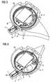
- the device D comprising the fixing device 2 and the hydraulic pitch cylinder 1 can be attached in particular screwed at a hub 40 of a wind turbine as can be seen from FIG 3 and FIG 4 .
- the flange 5 of the piston rod 4 of the hydraulic pitch cylinder 1 is connected to a moving part 41 of the hub 40 in form of a rotatable plate 41 defining an adjusting plane P.
- the rotatable plate 41 is connected to a rotor blade of a wind turbine.
- the other end of the hydraulic pitch cylinder 1 is arranged through an opening of the hub 40 and is arranged in a housing 42.
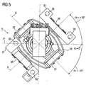
- the device D is in such a way arranged or fastened at the hub 40 by means of the flanges 38 and not shown screws or bolts that the first bearing shaft A and the second bearing shaft B are arranged respectively under a certain tilt angle ⁇ relatively to the adjusting plane P and the rotatable plate 41 respectively.
- FIG 5 This situation is explicitly shown in FIG 5 .
- the device D is compared with the known, initially mentioned arrangement of the bearing shafts tilted about approximately 45° relatively to the adjusting plane P and the rotatable plate 41 respectively.
- the angular or circular rotation during the adjustment of the pitch is divided substantially equally on both bearing shafts A and B.
- the load can be divided on the bearings substantially equally.
- the first and the second bearing shaft A, B are arranged substantially perpendicularly relatively to each other and are arranged substantially in a common plane.
- FIG 3 shows a first operating position of the hydraulic pitch cylinder 1 in particular of the piston rod 4 in which the pitch of the rotor blade is minimal.
- the piston rod 4 is adjusted relatively to the tube 3 the pitch can be adjusted respectively.
- the hydraulic pitch cylinder 1 pivots around the bearing shafts A and B.
- the fixing device 2 is a kind of pendulum bearing support of the hydraulic pitch cylinder 1 attachable to a hub of a wind turbine.
- FIG 4 the maximum pitch is shown.
- the attachment of the device D per se at the hub 40 can be unchanged compared with the known and initially mentioned arrangement what means that the device D is not tilted relatively to the adjusting plane P and the rotatable plate 41 respectively.
- the construction of the fixing device 2 in particular the arrangement of the bearings 32, 33 and 35, 36 at the fixing device 2 must be respectively adapted to receive tilted bearing shafts A and B relatively to the adjusting plane P and the rotatable plate 41 respectively to divide the angular or circular rotation during the adjustment of the pitch substantially equally on both bearing shafts A and B.
- the tilt angel of the first bearing shaft A needs not to be. -45° and the tilt angle of the second bearing shaft B needs not to be +45° relatively to the adjusting plane P and the rotatable plate 41 respectively.
- the tilt angle of the first bearing shaft A can be chosen in the range of +10° to +80° or in the range of -10° and -80°.
- the tilt angle of the second bearing shaft B can be chosen in the range of +10° to +80° or in the range of -10° and -80°.
- the tilt angles of the first and the second bearing shafts A, B are chosen such that the angular or circular rotation and/or the loads of the hydraulic pitch cylinder 1 are divided preferably substantially equally onto all bearings 32, 33, 35, 36.
- first and the second bearing shaft need not to be arranged substantially perpendicularly to each other or substantially in a common plane.
- the first ring-like element 20 and the second ring-like element 21 can be pressed towards the respective stop ring 10, 11 by at least one cramp 50 e.g. as shown in FIG 6 .
- the first ring-like element 20 and the second ring-like element 21 can have instead of the clearance holes, through borings or screw holes one or more slots around their perimeter in the sides 51, 52 which receive respectively at least one end of a cramp 50.
- the cramps 50 e.g. made of an elastic material press the first ring-like element 20 and the second ring-like element 21 towards the respective stop ring 10, 11.
- the stop ring 10 can be arranged at the side 51 of the first ring-like element 20 and the stop ring 11 can be arranged at the side 52 of the second ring-like element 21 in respective not shown grooves.
- at least one spreader 60 e.g. as shown in FIG 7 is used between the side 22 of the first ring-like element 20 and the side 26 of the second ring-like element 21.
- the spreader of FIG 7 comprises two screws 61, 62 and a retainer 63 with screw threads 64. By turning the retainer 63 in a certain direction the screws 61, 62 move out of the retainer 63. With such spreaders 60 the first ring-like element 20 can be pressed towards its stop ring and the second ring-like element 21 can be pressed towards its stop ring.
- the stopper can also be a projection e.g. a ring-like projection 70 on the outside of the tube 3 as schematically shown in FIG 8 .
- both stoppers can be a stop ring, both stoppers can be a projection or one stopper can be a stop ring and the other stopper can be a projection.
- the pitch actuator needs not to be a hydraulic pitch cylinder.
- the pitch actuator can also be an electric pitch actuator.
- contours of the outside of the tube and the inside of the first ring-like element and of the second ring-like element need not to be substantially roundly. It is also possible that the contours comprise edges or other forms as long as they fit.
- a device D according to the invention is assigned to each rotor blade of a wind turbine.
- the device D needs thereby not to be connected to a plate 41.
- the device D can also be connected to another element connected to a rotor blade of a wind turbine.
- the device D can also be attached or fastened at a rotor blade of a wind turbine.
- the flange 5 is attached e.g. to a fixed plate or another fixed element of a hub defining an adjusting plane. If the device D is operated the piston rod 4 moves out of the tube 3 wherein the rotor blade is pivoted relatively to the hub.
- each rotor blade is pivoted in a common way relatively to the hub.
- the invention refers also to a wind turbine comprising a hub, at least one rotor blade and a described device for the adjustment of the pitch of the rotor blade.
Landscapes
- Engineering & Computer Science (AREA)
- Life Sciences & Earth Sciences (AREA)
- Sustainable Development (AREA)
- Sustainable Energy (AREA)
- Chemical & Material Sciences (AREA)
- Combustion & Propulsion (AREA)
- Mechanical Engineering (AREA)
- General Engineering & Computer Science (AREA)
- Physics & Mathematics (AREA)
- Fluid Mechanics (AREA)
- Wind Motors (AREA)
Priority Applications (4)
| Application Number | Priority Date | Filing Date | Title |
|---|---|---|---|
| DK07010505.1T DK1995454T3 (da) | 2007-05-25 | 2007-05-25 | Indretning til regulering af hældningsvinklen af en rotorvinge af en vindmølle |
| EP07010505.1A EP1995454B1 (en) | 2007-05-25 | 2007-05-25 | Device for the adjustment of the pitch of a rotor blade of a wind turbine |
| US12/154,309 US8105036B2 (en) | 2007-05-25 | 2008-05-22 | Device for the adjustment of the pitch of a rotor blade of a wind turbine |
| CA2634428A CA2634428C (en) | 2007-05-25 | 2008-05-23 | Device for the adjustment of the pitch of a rotor blade of a wind turbine |
Applications Claiming Priority (1)
| Application Number | Priority Date | Filing Date | Title |
|---|---|---|---|
| EP07010505.1A EP1995454B1 (en) | 2007-05-25 | 2007-05-25 | Device for the adjustment of the pitch of a rotor blade of a wind turbine |
Publications (2)
| Publication Number | Publication Date |
|---|---|
| EP1995454A1 EP1995454A1 (en) | 2008-11-26 |
| EP1995454B1 true EP1995454B1 (en) | 2016-04-20 |
Family
ID=38983706
Family Applications (1)
| Application Number | Title | Priority Date | Filing Date |
|---|---|---|---|
| EP07010505.1A Not-in-force EP1995454B1 (en) | 2007-05-25 | 2007-05-25 | Device for the adjustment of the pitch of a rotor blade of a wind turbine |
Country Status (4)
| Country | Link |
|---|---|
| US (1) | US8105036B2 (da) |
| EP (1) | EP1995454B1 (da) |
| CA (1) | CA2634428C (da) |
| DK (1) | DK1995454T3 (da) |
Families Citing this family (7)
| Publication number | Priority date | Publication date | Assignee | Title |
|---|---|---|---|---|
| NO328590B1 (no) * | 2008-07-03 | 2010-03-29 | Hydra Tidal Energy Technology | Innretning for regulering av turbinbladstigning |
| US8414266B2 (en) * | 2008-09-26 | 2013-04-09 | Chi Hung Louis Lam | Traverse axis fluid turbine with controllable blades |
| JP4865862B2 (ja) * | 2008-12-19 | 2012-02-01 | 三菱重工業株式会社 | 風力発電装置のピッチ駆動装置および風力発電装置 |
| EP2703644B1 (en) * | 2012-08-27 | 2016-08-03 | Alstom Wind, S.L.U. | Angular positioning system for a wind turbine |
| DK2703666T3 (da) * | 2012-08-27 | 2018-07-23 | Ge Renewable Tech | Roterende system til en vindmølle |
| DE102014200674A1 (de) * | 2014-01-16 | 2015-07-16 | Zf Friedrichshafen Ag | Anschlussstück für ein Pitchrohr |
| EP3653870B1 (en) * | 2018-11-13 | 2021-06-30 | Siemens Gamesa Renewable Energy A/S | Pitch bearing arrangement |
Family Cites Families (11)
| Publication number | Priority date | Publication date | Assignee | Title |
|---|---|---|---|---|
| DE2655026C2 (de) * | 1976-12-04 | 1979-01-18 | Ulrich Prof. Dr.-Ing. 7312 Kirchheim Huetter | Windenergiekonverter |
| DE2715584A1 (de) | 1977-04-07 | 1978-10-19 | Franz Xaver Prof Dr I Wortmann | Windenergieanlage mit aerodynamischer selbststeuerung |
| US4431375A (en) | 1979-05-10 | 1984-02-14 | Carter Wind Power | Wind-driven generator apparatus |
| US4363241A (en) | 1980-12-23 | 1982-12-14 | United Technologies Corporation | Rotational speed governor |
| US4352629A (en) | 1981-10-19 | 1982-10-05 | United Technologies Corporation | Wind turbine |
| US4545728A (en) | 1983-08-30 | 1985-10-08 | Cheney Jr Marvin C | Wind turbine generator with improved operating subassemblies |
| US5028210A (en) * | 1990-01-05 | 1991-07-02 | The United States Of America As Represented By The Secretary Of The Navy | Propeller unit with controlled cyclic and collective blade pitch |
| US6327957B1 (en) | 1998-01-09 | 2001-12-11 | Wind Eagle Joint Venture | Wind-driven electric generator apparatus of the downwind type with flexible changeable-pitch blades |
| EP1126163A1 (en) * | 2000-02-16 | 2001-08-22 | Turbowinds N.V./S.A. | Blade pitch angle control device for wind turbine |
| US6981844B2 (en) * | 2003-10-08 | 2006-01-03 | Hamilton Sundstrand | Cyclic actuation system for a controllable pitch propeller and a method of providing aircraft control therewith |
| JP5199607B2 (ja) * | 2007-05-25 | 2013-05-15 | 三菱重工業株式会社 | 風力発電装置のピッチ駆動装置および風力発電装置 |
-
2007
- 2007-05-25 DK DK07010505.1T patent/DK1995454T3/da active
- 2007-05-25 EP EP07010505.1A patent/EP1995454B1/en not_active Not-in-force
-
2008
- 2008-05-22 US US12/154,309 patent/US8105036B2/en not_active Expired - Fee Related
- 2008-05-23 CA CA2634428A patent/CA2634428C/en not_active Expired - Fee Related
Also Published As
| Publication number | Publication date |
|---|---|
| CA2634428A1 (en) | 2008-11-25 |
| US8105036B2 (en) | 2012-01-31 |
| EP1995454A1 (en) | 2008-11-26 |
| CA2634428C (en) | 2015-06-30 |
| DK1995454T3 (da) | 2016-06-13 |
| US20080292463A1 (en) | 2008-11-27 |
Similar Documents
| Publication | Publication Date | Title |
|---|---|---|
| EP1995453B1 (en) | Device for the adjustment of the pitch of a rotor blade of a wind turbine | |
| EP1995454B1 (en) | Device for the adjustment of the pitch of a rotor blade of a wind turbine | |
| US9011010B2 (en) | Hybrid wind turbine blade bearing | |
| US6428274B1 (en) | Drive mechanism for adjusting the rotor blades of wind power installations | |
| CN109661340B (zh) | 杆型制动装置 | |
| KR20110089293A (ko) | 풍력 발전 장치 | |
| EP2597304B1 (en) | Wind turbine with a mechanism for synchronously varying the pitch of a multi-blade rotor | |
| KR20110084958A (ko) | 풍력 발전 장치 | |
| US20140369836A1 (en) | Turbine with hydraulic variable pitch system | |
| US8753085B2 (en) | Device for changing a pitch of a blade of an impeller/propeller and a fan comprising the device | |
| AU2008258839A1 (en) | Bearing arrangement for a wind turbine | |
| EP3411591B1 (en) | Wind turbine pitch actuator mounting structure | |
| JP4227527B2 (ja) | 線形油圧式揺動駆動装置 | |
| EP2531725B1 (en) | Hybrid wind turbine blade bearing | |
| EP2679815B1 (en) | Wind turbine with a rotating assembly | |
| US20200011304A1 (en) | Yaw bearing arrangement | |
| JPS6354144B2 (da) | ||
| US20240410419A1 (en) | Bearing arrangement for a rotating component of a wind turbine | |
| EP4474663A1 (en) | Bearing arrangement for a rotating component of a wind turbine | |
| GB2626669A (en) | Passive pitch system | |
| GB2209806A (en) | Blade pitch change mechanism | |
| KR20020083096A (ko) | 풍력발전의 피치 제어장치 | |
| JP2004239094A (ja) | ガイドベーンの開閉装置 |
Legal Events
| Date | Code | Title | Description |
|---|---|---|---|
| PUAI | Public reference made under article 153(3) epc to a published international application that has entered the european phase |
Free format text: ORIGINAL CODE: 0009012 |
|
| 17P | Request for examination filed |
Effective date: 20080312 |
|
| AK | Designated contracting states |
Kind code of ref document: A1 Designated state(s): AT BE BG CH CY CZ DE DK EE ES FI FR GB GR HU IE IS IT LI LT LU LV MC MT NL PL PT RO SE SI SK TR |
|
| AX | Request for extension of the european patent |
Extension state: AL BA HR MK RS |
|
| AKX | Designation fees paid |
Designated state(s): DE DK ES GB |
|
| RAP1 | Party data changed (applicant data changed or rights of an application transferred) |
Owner name: SIEMENS AKTIENGESELLSCHAFT |
|
| GRAP | Despatch of communication of intention to grant a patent |
Free format text: ORIGINAL CODE: EPIDOSNIGR1 |
|
| INTG | Intention to grant announced |
Effective date: 20151023 |
|
| GRAS | Grant fee paid |
Free format text: ORIGINAL CODE: EPIDOSNIGR3 |
|
| GRAA | (expected) grant |
Free format text: ORIGINAL CODE: 0009210 |
|
| RIC1 | Information provided on ipc code assigned before grant |
Ipc: F03D 7/02 20060101AFI20160303BHEP Ipc: F03D 80/00 20160101ALI20160303BHEP Ipc: F03D 15/00 20160101ALI20160303BHEP |
|
| AK | Designated contracting states |
Kind code of ref document: B1 Designated state(s): DE DK ES GB |
|
| REG | Reference to a national code |
Ref country code: GB Ref legal event code: FG4D |
|
| REG | Reference to a national code |
Ref country code: DE Ref legal event code: R096 Ref document number: 602007045910 Country of ref document: DE |
|
| REG | Reference to a national code |
Ref country code: DK Ref legal event code: T3 Effective date: 20160606 |
|
| PGFP | Annual fee paid to national office [announced via postgrant information from national office to epo] |
Ref country code: DE Payment date: 20160720 Year of fee payment: 10 |
|
| PG25 | Lapsed in a contracting state [announced via postgrant information from national office to epo] |
Ref country code: ES Free format text: LAPSE BECAUSE OF FAILURE TO SUBMIT A TRANSLATION OF THE DESCRIPTION OR TO PAY THE FEE WITHIN THE PRESCRIBED TIME-LIMIT Effective date: 20160420 |
|
| REG | Reference to a national code |
Ref country code: DE Ref legal event code: R097 Ref document number: 602007045910 Country of ref document: DE |
|
| PLBE | No opposition filed within time limit |
Free format text: ORIGINAL CODE: 0009261 |
|
| STAA | Information on the status of an ep patent application or granted ep patent |
Free format text: STATUS: NO OPPOSITION FILED WITHIN TIME LIMIT |
|
| 26N | No opposition filed |
Effective date: 20170123 |
|
| PGFP | Annual fee paid to national office [announced via postgrant information from national office to epo] |
Ref country code: GB Payment date: 20170508 Year of fee payment: 11 Ref country code: DK Payment date: 20170519 Year of fee payment: 11 |
|
| REG | Reference to a national code |
Ref country code: DE Ref legal event code: R119 Ref document number: 602007045910 Country of ref document: DE |
|
| PG25 | Lapsed in a contracting state [announced via postgrant information from national office to epo] |
Ref country code: DE Free format text: LAPSE BECAUSE OF NON-PAYMENT OF DUE FEES Effective date: 20171201 |
|
| REG | Reference to a national code |
Ref country code: DK Ref legal event code: EBP Effective date: 20180531 |
|
| GBPC | Gb: european patent ceased through non-payment of renewal fee |
Effective date: 20180525 |
|
| PG25 | Lapsed in a contracting state [announced via postgrant information from national office to epo] |
Ref country code: GB Free format text: LAPSE BECAUSE OF NON-PAYMENT OF DUE FEES Effective date: 20180525 |
|
| PG25 | Lapsed in a contracting state [announced via postgrant information from national office to epo] |
Ref country code: DK Free format text: LAPSE BECAUSE OF NON-PAYMENT OF DUE FEES Effective date: 20180531 |