EP1995397B1 - Glattwandsilo - Google Patents
Glattwandsilo Download PDFInfo
- Publication number
- EP1995397B1 EP1995397B1 EP07010472A EP07010472A EP1995397B1 EP 1995397 B1 EP1995397 B1 EP 1995397B1 EP 07010472 A EP07010472 A EP 07010472A EP 07010472 A EP07010472 A EP 07010472A EP 1995397 B1 EP1995397 B1 EP 1995397B1
- Authority
- EP
- European Patent Office
- Prior art keywords
- wall
- cell
- silo
- set forth
- leg
- Prior art date
- Legal status (The legal status is an assumption and is not a legal conclusion. Google has not performed a legal analysis and makes no representation as to the accuracy of the status listed.)
- Not-in-force
Links
- 238000000638 solvent extraction Methods 0.000 claims 3
- 210000001503 joint Anatomy 0.000 claims 1
- 238000009415 formwork Methods 0.000 description 27
- 210000004027 cell Anatomy 0.000 description 18
- 238000010276 construction Methods 0.000 description 10
- 238000003466 welding Methods 0.000 description 6
- 235000013312 flour Nutrition 0.000 description 4
- 230000015572 biosynthetic process Effects 0.000 description 2
- 210000002421 cell wall Anatomy 0.000 description 2
- 239000013590 bulk material Substances 0.000 description 1
- 235000013339 cereals Nutrition 0.000 description 1
- 150000001875 compounds Chemical class 0.000 description 1
- 230000001419 dependent effect Effects 0.000 description 1
- 235000013305 food Nutrition 0.000 description 1
- 238000009434 installation Methods 0.000 description 1
- 238000000034 method Methods 0.000 description 1
- 230000000717 retained effect Effects 0.000 description 1
- 230000035939 shock Effects 0.000 description 1
Images

Classifications
-
- E—FIXED CONSTRUCTIONS
- E04—BUILDING
- E04H—BUILDINGS OR LIKE STRUCTURES FOR PARTICULAR PURPOSES; SWIMMING OR SPLASH BATHS OR POOLS; MASTS; FENCING; TENTS OR CANOPIES, IN GENERAL
- E04H7/00—Construction or assembling of bulk storage containers employing civil engineering techniques in situ or off the site
- E04H7/22—Containers for fluent solids, e.g. silos, bunkers; Supports therefor
- E04H7/24—Constructions, with or without perforated walls, depending on the use of specified materials
- E04H7/30—Constructions, with or without perforated walls, depending on the use of specified materials mainly of metal
Definitions
- the present invention relates to a cell for a smooth-walled silo comprising a plurality of wall elements, which communicate in the region of their corners by corner connecting plates to form a node column with each other, wherein the corner connecting plate has a stanchion leg having at its one end an angled connecting leg for connection to a adjacent connecting leg and at its other end has a fold, wherein the wall element has at least one formwork element.
- Silo container and in particular also smooth wall silos of the type mentioned are sufficiently known from the prior art.
- Such silo containers serve to accommodate a variety of goods, such. As cereals or flour.
- smooth-walled silos are distinguished by the fact that they have substantially no horizontally extending projections on which food, for. As flour, deposit could. That is, if such a silo is empty, then it is actually empty. This is not the case with silo containers having trapezoidal wall panels, such as. B. silo container according to DE 30 02 782 A1 , This is because residues of the bulk material, for example of flour, will still be in the region of the horizontally extending trapezoidal plates.
- a smooth wall silo container is already known from DT 24 09 678, which is characterized in that the walls of a cell are no longer trapezoidal, but smooth.
- To connect the individual wall elements with each other 90 ° angle or head plates are provided, which are bolted to the wall elements. The screwing is done by so-called bolts, which means that such a silo container is not directly to be mounted on a building wall, as at least during assembly to tighten the screws, the assembly staff must be able to get behind the silo wall.
- the matter is then, if for stability reasons, the individual wall elements are connected by rods. From this it is clear that the individual supports are connected by these rods with each other, the rods have a screw on the head side.
- the corner columns are formed from four trapezoidal column plates, wherein the cell walls run between the connecting flanges of two column plates.
- the connection between the individual column plates on the one hand and the cell walls on the other hand is done by tie bolts.
- a so-called square tube is provided, wherein the two outer plates and the square tube are connected by a tie bolt, wherein the formation of the corner pillars in cross-section trapezoidal shaped pillar plates are each also detected on both sides of the wall of this bolt.
- This construction has several disadvantages.
- silo container is not mounted directly in front of the wall.
- stability of the wall elements should be achieved. It can only be seen that two outer plates are provided, which together with the column plates form the silo container or the cell of a silo container in the region of the corner column. In this respect, it can be assumed that a silo container produced in this way can not reach any desired height, at least not if at the same time the desired properties for a smooth-walled silo are to be retained. This also applies to the known silo connector systems such. B. according to or DE 30 02 782 A1 , Here, although precautions are taken in conjunction with a Betonverguss the supports to build high (see Fig. 6).
- From the BE 694 416 A is a support structure for a smooth wall silo of the type mentioned above, wherein the individual formwork elements abut the support structure.
- the object underlying the invention is therefore to provide a smooth wall silo, in particular a smooth wall silo comprising a plurality of cells, which can be produced without limitation by the system or the design principle as such in any amount, which is constructed substantially directly on or in front of a wall which is hermetically sealed and stable and, moreover, requires only a few different components.
- each wall element end has in each case a vertical wall support in the installed state, wherein the two wall supports of a pair of supports of a wall element are connected over their height by a plurality of superimposed and spaced apart transverse struts, wherein the fold at one end the stanchion leg is directed in the direction of the transverse strut, wherein the shell element also has a fold at each end, wherein the two folds are in engagement with the transverse struts.
- the wall elements in the installed state on two vertically extending wall supports are interconnected by transverse struts, wherein the inside of a wall element of a silo is covered by formwork elements.
- the formwork elements themselves are provided on both sides with folds, wherein the folds of the formwork elements are in engagement with the cross struts. Bent in the same way are the EckMISsbleche so that in the region of the folds between the EckMISsblechen on the one hand and the formwork elements on the other hand shocks arise, which are interconnected by perpendicular welds.
- the construction without horizontal connections can reach a substantially unlimited height. That is, the height is not limited by the system.
- long, straight weld seams are provided, which can be produced by means of a tractor welding device.
- Such a silo can be mounted substantially immediately in front of an existing wall, since the nodal columns can remain open at the rear.
- a smooth wall silo can be produced with a plurality of cells, wherein there is not only a dense, but also a stable connection between the cross struts, formwork elements and corner elements.
- cross struts are designed to achieve a high stability in the manner of a U-profile.
- both the Eckitatisbleche and the formwork elements are by bends in engagement with the cross struts.
- the two folds with meandering Notches for detecting the transverse struts in the region of the legs of the cross struts are provided.
- the transverse struts, which point outwards with their closed legs, are thus open towards the bottom in the installed state, are respectively detected by the notch of the folds of the formwork elements or of the corner connecting plates.
- a vertically extending weld is arranged in the region of a joint between the two formwork elements or between a formwork element and a Ecktheticsblech, with the result that, since both the formwork elements and the Eckignantsbleche directly to the legs of the Abut transverse struts, during the welding process through the joint through a connection with the legs of the cross struts takes place.
- the cross strut in the region of the legs has slots for receiving the folds of both the Eckitatisbleche and the formwork elements.
- the connection between the formwork element and the Eckitatisblechen on the one hand and the crossbars on the other hand by a weld arranged in the region of the joints can then no longer be ensured.
- the formwork elements have openings in the region of the transverse struts. Through these openings, the shell elements can cohesively, z. B. by welding points, are connected to the cross braces.
- the angled from the support leg connecting arm of the Ecktheticsbleches an angle to the stanchion leg of Eckrivsbleches of about 45 °, wherein the two Connecting leg of the Eckrivsbleche advantageously overlap each other and in the overlapping area with each other z. B. are connected by screws.
- connection of two wall elements which are at an angle of 90 ° to each other, takes place in the region of the diagonals of the Eckitatisbleche, since this opens up the possibility of mounting such a silo immediately in front of the wall, because the screw can from Cell interior are made.
- high tensile forces can be transmitted by such a diagonal connection of two wall elements.
- the support leg of the Ecktheticsbleches forms a part of the jacket of the wall support. It is clear that a wall support can be formed as a whole square tube or even by two mutually parallel support legs of two Eckitatisbleche, in which case the two Eckitatisbleche be connected by two mutually parallel bars to a square to such a wall element stability lend, as it can be achieved, when used as wall supports directly square tubes are used.
- the construction according to the invention also has the advantage that a cell can be subdivided at any point by further walls with the existing construction elements, that is to say in particular the corner connecting plates.
- an intermediate wall element is provided for dividing a cell, wherein for connecting the intermediate wall element with the wall element of the cell, the EckMISsbleche have at their fold in the support area meandering notches, which are in engagement with the transverse struts of the wall element. Only the completeness It should be noted at this point that, conversely, the transverse struts can show slots for receiving the folds of the corner connecting plates, as has already been described elsewhere. It is clear from this that the construction according to the invention is extremely variable despite the small number of different components.
- the wall element for arranging a funnel receptacle on the wall element of a cell on at least one transverse strut in the form of a square tube wherein on the square tube, the funnel receptacle is arranged in the form of an angle to the wall element extending support plate.
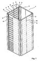
- FIG. 1 shows the cell 1 of a smooth wall silo, wherein at different points of the cell 1 of the smooth wall silo the formwork elements are omitted to illustrate the construction.
- the cell 1 has in detail four wall elements 2, which are connected in the corner region by connecting plates 3, 4.
- Each wall element 2 comprises two wall supports 5, which are connected by horizontally extending U-shaped transverse struts 6 ladder-shaped with each other.
- the arrangement of the U-shaped transverse struts is in this case such that the cross struts point with their open side in the installed state down.
- the ladder-shaped wall elements are clad by two mutually parallel shell elements 7 both on the inside and on the outside. Recognizable possess the shell elements each end a fold 7a, where - as in FIG. 1 recognizable, but especially in FIG. 3a shown - have the folds meandering notches 7b, so as to ensure that the formwork elements 7 can actually rest over the entire surface of the legs 6a of the cross braces 6.
- FIG. 3a a notch 7b of the fold 7a of the shell element 7;
- the transverse struts 6 for receiving the folds 7a of the formwork elements have a corresponding slot.
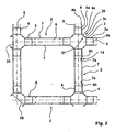
- the connecting plates 3 and 4 in the region of the support leg 3a, 4a also a fold 3b, 4b ( Fig. 2 )
- the above explanations apply mutatis mutandis to these folds.
- the transverse strut is designed in the region of a joint between two wall elements in the same way as in the area of a joint between a wall element and a connecting plate 3 or 4.
- the connecting plates 3, 4 have the support legs 3a, 4a, wherein the support legs 3a, 4a rests against the wall support 5.
- the support leg 3a, 4a has the end of the fold 3b, 4b, which forms a joint 15 in conjunction with the respective fold 7a of the shell element 7, which receives a vertically extending weld in the assembled state of the silo.
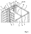
- each node column can be manufactured with identical corner connection plates.
- the open legs of such a node column can be closed by appropriately trained end plates 30, 35.
- end plates 30, 35 there is also the possibility to omit these end plates 30, 35, since the node columns need not be closed for reasons of stability, as has already been explained.
- an intermediate wall element 40 is provided, wherein the intermediate wall element 40 is formed exactly the same as the wall element 2.
- the connection of this intermediate wall element 40 to the wall element 2 is made in the same way with the known Eckitatisblechen 3, 4, as well as the formation of a node column is known. Only the support leg of the connecting plate is no longer in a wall on a support, but only on the cross struts. This works because of the intermediate wall 40 due to the wall supports 5 no vertical loads, but only horizontal loads are delivered to the wall 2.
- the formwork elements in the region of the transverse struts 6 are provided with openings 9 through which the formwork elements 7 are fixed to the transverse struts 6 by means of spot welds to form a shear bond. It has already been pointed out elsewhere that due to the notches 7b both the formwork elements 7 and the fold 3b, 4b of the connection plates, both the wall elements and the connection plates rest directly on the cross struts 6, so that when welding in the area the joint is directly connected to the underlying transverse strut 6.
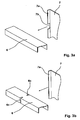
- FIG. 4 schematically, the arrangement of a horizontally extending square tube 45 is provided in the wall element 2, wherein on the square tube 45 as a funnel receptacle 46, a support plate is arranged.
- This support plate is connected for example by a weld with the horizontally extending square tube 45.
- the formwork elements 7 no longer run through, but continue upwards and downwards as independent wall elements.
Landscapes
- Engineering & Computer Science (AREA)
- Architecture (AREA)
- General Engineering & Computer Science (AREA)
- Civil Engineering (AREA)
- Structural Engineering (AREA)
- Filling Or Emptying Of Bunkers, Hoppers, And Tanks (AREA)
- Cyclones (AREA)
- Storage Of Harvested Produce (AREA)
Priority Applications (5)
| Application Number | Priority Date | Filing Date | Title |
|---|---|---|---|
| DK07010472T DK1995397T3 (da) | 2007-05-25 | 2007-05-25 | Glatvægssilo |
| AT07010472T ATE434098T1 (de) | 2007-05-25 | 2007-05-25 | Glattwandsilo |
| PL07010472T PL1995397T3 (pl) | 2007-05-25 | 2007-05-25 | Silos z gładkimi ścianami |
| DE502007000905T DE502007000905D1 (de) | 2007-05-25 | 2007-05-25 | Glattwandsilo |
| EP07010472A EP1995397B1 (de) | 2007-05-25 | 2007-05-25 | Glattwandsilo |
Applications Claiming Priority (1)
| Application Number | Priority Date | Filing Date | Title |
|---|---|---|---|
| EP07010472A EP1995397B1 (de) | 2007-05-25 | 2007-05-25 | Glattwandsilo |
Publications (2)
| Publication Number | Publication Date |
|---|---|
| EP1995397A1 EP1995397A1 (de) | 2008-11-26 |
| EP1995397B1 true EP1995397B1 (de) | 2009-06-17 |
Family
ID=38596790
Family Applications (1)
| Application Number | Title | Priority Date | Filing Date |
|---|---|---|---|
| EP07010472A Not-in-force EP1995397B1 (de) | 2007-05-25 | 2007-05-25 | Glattwandsilo |
Country Status (5)
| Country | Link |
|---|---|
| EP (1) | EP1995397B1 (pl) |
| AT (1) | ATE434098T1 (pl) |
| DE (1) | DE502007000905D1 (pl) |
| DK (1) | DK1995397T3 (pl) |
| PL (1) | PL1995397T3 (pl) |
Families Citing this family (5)
| Publication number | Priority date | Publication date | Assignee | Title |
|---|---|---|---|---|
| DE202016104178U1 (de) | 2016-07-29 | 2017-11-02 | Markus Becker | Silo |
| PL71419Y1 (pl) * | 2018-03-30 | 2020-05-18 | Aqua World Spolka Z Ograniczona Odpowiedzialnoscia | Konstrukcja wzmacniająca zbiorniki plastikowe składająca się z metalowych obejm o profilu zamkniętym i plastikowych żeber |
| PL127198U1 (pl) * | 2018-03-30 | 2019-10-07 | Aqua World Spółka Z Ograniczoną Odpowiedzialnością | Konstrukcja wzmacniająca zbiorniki plastikowe składająca się z metalowych obejm o profilu zamkniętym i plastikowych podpór |
| PL71418Y1 (pl) * | 2018-03-30 | 2020-05-18 | Aqua World Spolka Z Ograniczona Odpowiedzialnoscia | Konstrukcja wzmacniająca zbiorniki plastikowe składająca się z metalowych obejm o profilu otwartym i plastikowych żeber |
| PL127197U1 (pl) * | 2018-03-30 | 2019-10-07 | Aqua World Spółka Z Ograniczoną Odpowiedzialnością | Konstrukcja wzmacniająca zbiorniki plastikowe składające się z metalowych obejm o profilu otwartym i plastikowych podpór |
Family Cites Families (5)
| Publication number | Priority date | Publication date | Assignee | Title |
|---|---|---|---|---|
| BE694416A (pl) | 1967-02-22 | 1967-07-31 | ||
| GB1217732A (en) * | 1968-04-01 | 1970-12-31 | Philip Harry Collier | Improvements in wall structures for storage bins |
| AT360911B (de) | 1979-03-07 | 1980-02-10 | Geroldinger Walter Ohg | Zellensilo |
| DE3002782C2 (de) | 1980-01-26 | 1982-01-28 | Industriebau und Wärmetechnik GmbH, 8670 Hof | Stütze für einen Zellensilo |
| PL329384A1 (en) * | 1996-04-18 | 1999-03-29 | Rionde Sa | Wall or shell consisting of metal sheets bracked on a skeleton or a skeleton-like structure and method of constructing same |
-
2007
- 2007-05-25 EP EP07010472A patent/EP1995397B1/de not_active Not-in-force
- 2007-05-25 PL PL07010472T patent/PL1995397T3/pl unknown
- 2007-05-25 DE DE502007000905T patent/DE502007000905D1/de active Active
- 2007-05-25 AT AT07010472T patent/ATE434098T1/de active
- 2007-05-25 DK DK07010472T patent/DK1995397T3/da active
Also Published As
| Publication number | Publication date |
|---|---|
| ATE434098T1 (de) | 2009-07-15 |
| EP1995397A1 (de) | 2008-11-26 |
| PL1995397T3 (pl) | 2009-10-30 |
| DK1995397T3 (da) | 2009-07-27 |
| DE502007000905D1 (de) | 2009-07-30 |
Similar Documents
| Publication | Publication Date | Title |
|---|---|---|
| EP1995397B1 (de) | Glattwandsilo | |
| EP2072685A1 (de) | Gründungsstruktur für Offshore-Bauwerke, insbesondere für Offshore-Windenergieanlagen, und Verfahren zur Herstellung derselben | |
| EP2455305B1 (de) | Silo | |
| DE202007003206U1 (de) | Modularer Träger für Bedachungen großer Flächen | |
| AT502604B1 (de) | Verbundstütze für knotenverbindungen von bauwerken sowie gebäudeskelett | |
| EP2060680A1 (de) | Stütze für Hochwasserschutzwand | |
| DE3837475C1 (pl) | ||
| DE202008012407U1 (de) | Freitragende Stahlhalle | |
| DE3923613C2 (de) | Systemelement für einen kombinierten rohrförmigen Füll- und Entnahmeschacht | |
| DE2209484C3 (de) | Druckfester Transcontainer für fließfähige Güter | |
| DE202013104353U1 (de) | Überflurfördereinrichtung zur Lagerung an der Decke einer Montageanlage | |
| DE102006044790A1 (de) | Brücke mit zwei fachwerkartig ausgebildeten Scheiben und Bausatz zu deren Herstellung | |
| DE1259553B (de) | Silo oder aehnliches Bauwerk mit Wandung aus Saeulen und Wellblechplatten | |
| AT391342B (de) | Seitenwandelement, vorzugsweise aus stahlblech, fuer die errichtung von selbsttragenden silobehaeltermantelwaenden | |
| DE1684837C3 (de) | Stahlblechsilo aus doppelschaligen Wandelementen | |
| DE1892804U (de) | Bauelementensatz fuer stahlsilos in zellenbauweise. | |
| DE3444645C2 (pl) | ||
| DE3840805A1 (de) | Schnell montierbarer und demontierbarer behaelter | |
| DE2853325C2 (de) | Oberteil für Silos | |
| DE1684898C3 (de) | Tafelartiges Bauelement fur die Wände von Behaltern, insbesondere Silos | |
| DE8330257U1 (de) | Doppelwandige stahlverbauplatte | |
| DE202016104178U1 (de) | Silo | |
| DE202005006228U1 (de) | Dachkonstruktion für Gebäude, insbesondere für Industriegebäude mit großen Spannweiten | |
| DE102020110043A1 (de) | Silo | |
| DE7717553U1 (de) | Stapelbarer Container |
Legal Events
| Date | Code | Title | Description |
|---|---|---|---|
| PUAI | Public reference made under article 153(3) epc to a published international application that has entered the european phase |
Free format text: ORIGINAL CODE: 0009012 |
|
| 17P | Request for examination filed |
Effective date: 20071227 |
|
| AK | Designated contracting states |
Kind code of ref document: A1 Designated state(s): AT BE BG CH CY CZ DE DK EE ES FI FR GB GR HU IE IS IT LI LT LU LV MC MT NL PL PT RO SE SI SK TR |
|
| AX | Request for extension of the european patent |
Extension state: AL BA HR MK RS |
|
| GRAP | Despatch of communication of intention to grant a patent |
Free format text: ORIGINAL CODE: EPIDOSNIGR1 |
|
| GRAS | Grant fee paid |
Free format text: ORIGINAL CODE: EPIDOSNIGR3 |
|
| GRAA | (expected) grant |
Free format text: ORIGINAL CODE: 0009210 |
|
| AK | Designated contracting states |
Kind code of ref document: B1 Designated state(s): AT BE BG CH CY CZ DE DK EE ES FI FR GB GR HU IE IS IT LI LT LU LV MC MT NL PL PT RO SE SI SK TR |
|
| REG | Reference to a national code |
Ref country code: GB Ref legal event code: FG4D Free format text: NOT ENGLISH |
|
| REG | Reference to a national code |
Ref country code: CH Ref legal event code: EP |
|
| REG | Reference to a national code |
Ref country code: IE Ref legal event code: FG4D Free format text: LANGUAGE OF EP DOCUMENT: GERMAN |
|
| REG | Reference to a national code |
Ref country code: DK Ref legal event code: T3 |
|
| AKX | Designation fees paid |
Designated state(s): AT BE BG CH CY CZ DE DK EE ES FI FR GB GR HU IE IS IT LI LT LU LV MC MT NL PL PT RO SE SI SK TR |
|
| REF | Corresponds to: |
Ref document number: 502007000905 Country of ref document: DE Date of ref document: 20090730 Kind code of ref document: P |
|
| REG | Reference to a national code |
Ref country code: CH Ref legal event code: NV Representative=s name: R. A. EGLI & CO. PATENTANWAELTE |
|
| PG25 | Lapsed in a contracting state [announced via postgrant information from national office to epo] |
Ref country code: LT Free format text: LAPSE BECAUSE OF FAILURE TO SUBMIT A TRANSLATION OF THE DESCRIPTION OR TO PAY THE FEE WITHIN THE PRESCRIBED TIME-LIMIT Effective date: 20090617 Ref country code: FI Free format text: LAPSE BECAUSE OF FAILURE TO SUBMIT A TRANSLATION OF THE DESCRIPTION OR TO PAY THE FEE WITHIN THE PRESCRIBED TIME-LIMIT Effective date: 20090617 |
|
| REG | Reference to a national code |
Ref country code: PL Ref legal event code: T3 |
|
| PG25 | Lapsed in a contracting state [announced via postgrant information from national office to epo] |
Ref country code: SE Free format text: LAPSE BECAUSE OF FAILURE TO SUBMIT A TRANSLATION OF THE DESCRIPTION OR TO PAY THE FEE WITHIN THE PRESCRIBED TIME-LIMIT Effective date: 20090917 Ref country code: SI Free format text: LAPSE BECAUSE OF FAILURE TO SUBMIT A TRANSLATION OF THE DESCRIPTION OR TO PAY THE FEE WITHIN THE PRESCRIBED TIME-LIMIT Effective date: 20090617 Ref country code: LV Free format text: LAPSE BECAUSE OF FAILURE TO SUBMIT A TRANSLATION OF THE DESCRIPTION OR TO PAY THE FEE WITHIN THE PRESCRIBED TIME-LIMIT Effective date: 20090617 |
|
| REG | Reference to a national code |
Ref country code: IE Ref legal event code: FD4D |
|
| PG25 | Lapsed in a contracting state [announced via postgrant information from national office to epo] |
Ref country code: IE Free format text: LAPSE BECAUSE OF FAILURE TO SUBMIT A TRANSLATION OF THE DESCRIPTION OR TO PAY THE FEE WITHIN THE PRESCRIBED TIME-LIMIT Effective date: 20090617 Ref country code: EE Free format text: LAPSE BECAUSE OF FAILURE TO SUBMIT A TRANSLATION OF THE DESCRIPTION OR TO PAY THE FEE WITHIN THE PRESCRIBED TIME-LIMIT Effective date: 20090617 Ref country code: RO Free format text: LAPSE BECAUSE OF FAILURE TO SUBMIT A TRANSLATION OF THE DESCRIPTION OR TO PAY THE FEE WITHIN THE PRESCRIBED TIME-LIMIT Effective date: 20090617 Ref country code: IS Free format text: LAPSE BECAUSE OF FAILURE TO SUBMIT A TRANSLATION OF THE DESCRIPTION OR TO PAY THE FEE WITHIN THE PRESCRIBED TIME-LIMIT Effective date: 20091017 Ref country code: ES Free format text: LAPSE BECAUSE OF FAILURE TO SUBMIT A TRANSLATION OF THE DESCRIPTION OR TO PAY THE FEE WITHIN THE PRESCRIBED TIME-LIMIT Effective date: 20090928 |
|
| PG25 | Lapsed in a contracting state [announced via postgrant information from national office to epo] |
Ref country code: SK Free format text: LAPSE BECAUSE OF FAILURE TO SUBMIT A TRANSLATION OF THE DESCRIPTION OR TO PAY THE FEE WITHIN THE PRESCRIBED TIME-LIMIT Effective date: 20090617 |
|
| PG25 | Lapsed in a contracting state [announced via postgrant information from national office to epo] |
Ref country code: PT Free format text: LAPSE BECAUSE OF FAILURE TO SUBMIT A TRANSLATION OF THE DESCRIPTION OR TO PAY THE FEE WITHIN THE PRESCRIBED TIME-LIMIT Effective date: 20091017 Ref country code: BG Free format text: LAPSE BECAUSE OF FAILURE TO SUBMIT A TRANSLATION OF THE DESCRIPTION OR TO PAY THE FEE WITHIN THE PRESCRIBED TIME-LIMIT Effective date: 20090917 |
|
| PLBE | No opposition filed within time limit |
Free format text: ORIGINAL CODE: 0009261 |
|
| STAA | Information on the status of an ep patent application or granted ep patent |
Free format text: STATUS: NO OPPOSITION FILED WITHIN TIME LIMIT |
|
| 26N | No opposition filed |
Effective date: 20100318 |
|
| PG25 | Lapsed in a contracting state [announced via postgrant information from national office to epo] |
Ref country code: GR Free format text: LAPSE BECAUSE OF FAILURE TO SUBMIT A TRANSLATION OF THE DESCRIPTION OR TO PAY THE FEE WITHIN THE PRESCRIBED TIME-LIMIT Effective date: 20090918 |
|
| PG25 | Lapsed in a contracting state [announced via postgrant information from national office to epo] |
Ref country code: MC Free format text: LAPSE BECAUSE OF NON-PAYMENT OF DUE FEES Effective date: 20100531 |
|
| PG25 | Lapsed in a contracting state [announced via postgrant information from national office to epo] |
Ref country code: IT Free format text: LAPSE BECAUSE OF NON-PAYMENT OF DUE FEES Effective date: 20100525 |
|
| PG25 | Lapsed in a contracting state [announced via postgrant information from national office to epo] |
Ref country code: MT Free format text: LAPSE BECAUSE OF FAILURE TO SUBMIT A TRANSLATION OF THE DESCRIPTION OR TO PAY THE FEE WITHIN THE PRESCRIBED TIME-LIMIT Effective date: 20090617 |
|
| PG25 | Lapsed in a contracting state [announced via postgrant information from national office to epo] |
Ref country code: CY Free format text: LAPSE BECAUSE OF FAILURE TO SUBMIT A TRANSLATION OF THE DESCRIPTION OR TO PAY THE FEE WITHIN THE PRESCRIBED TIME-LIMIT Effective date: 20090617 |
|
| PG25 | Lapsed in a contracting state [announced via postgrant information from national office to epo] |
Ref country code: LU Free format text: LAPSE BECAUSE OF NON-PAYMENT OF DUE FEES Effective date: 20100525 Ref country code: HU Free format text: LAPSE BECAUSE OF FAILURE TO SUBMIT A TRANSLATION OF THE DESCRIPTION OR TO PAY THE FEE WITHIN THE PRESCRIBED TIME-LIMIT Effective date: 20091218 |
|
| PG25 | Lapsed in a contracting state [announced via postgrant information from national office to epo] |
Ref country code: TR Free format text: LAPSE BECAUSE OF FAILURE TO SUBMIT A TRANSLATION OF THE DESCRIPTION OR TO PAY THE FEE WITHIN THE PRESCRIBED TIME-LIMIT Effective date: 20090617 |
|
| PGFP | Annual fee paid to national office [announced via postgrant information from national office to epo] |
Ref country code: GB Payment date: 20140521 Year of fee payment: 8 |
|
| PGFP | Annual fee paid to national office [announced via postgrant information from national office to epo] |
Ref country code: CH Payment date: 20140521 Year of fee payment: 8 Ref country code: FR Payment date: 20140527 Year of fee payment: 8 Ref country code: IT Payment date: 20140527 Year of fee payment: 8 Ref country code: NL Payment date: 20140521 Year of fee payment: 8 |
|
| PGFP | Annual fee paid to national office [announced via postgrant information from national office to epo] |
Ref country code: PL Payment date: 20140424 Year of fee payment: 8 Ref country code: DK Payment date: 20140521 Year of fee payment: 8 Ref country code: BE Payment date: 20140523 Year of fee payment: 8 |
|
| REG | Reference to a national code |
Ref country code: DK Ref legal event code: EBP Effective date: 20150531 |
|
| REG | Reference to a national code |
Ref country code: CH Ref legal event code: PL |
|
| GBPC | Gb: european patent ceased through non-payment of renewal fee |
Effective date: 20150525 |
|
| PG25 | Lapsed in a contracting state [announced via postgrant information from national office to epo] |
Ref country code: LI Free format text: LAPSE BECAUSE OF NON-PAYMENT OF DUE FEES Effective date: 20150531 Ref country code: IT Free format text: LAPSE BECAUSE OF NON-PAYMENT OF DUE FEES Effective date: 20150525 Ref country code: CH Free format text: LAPSE BECAUSE OF NON-PAYMENT OF DUE FEES Effective date: 20150531 |
|
| REG | Reference to a national code |
Ref country code: NL Ref legal event code: MM Effective date: 20150601 |
|
| REG | Reference to a national code |
Ref country code: FR Ref legal event code: ST Effective date: 20160129 |
|
| PG25 | Lapsed in a contracting state [announced via postgrant information from national office to epo] |
Ref country code: NL Free format text: LAPSE BECAUSE OF NON-PAYMENT OF DUE FEES Effective date: 20150601 Ref country code: GB Free format text: LAPSE BECAUSE OF NON-PAYMENT OF DUE FEES Effective date: 20150525 Ref country code: DK Free format text: LAPSE BECAUSE OF NON-PAYMENT OF DUE FEES Effective date: 20150531 |
|
| PG25 | Lapsed in a contracting state [announced via postgrant information from national office to epo] |
Ref country code: FR Free format text: LAPSE BECAUSE OF NON-PAYMENT OF DUE FEES Effective date: 20150601 |
|
| PG25 | Lapsed in a contracting state [announced via postgrant information from national office to epo] |
Ref country code: PL Free format text: LAPSE BECAUSE OF NON-PAYMENT OF DUE FEES Effective date: 20150525 |
|
| PG25 | Lapsed in a contracting state [announced via postgrant information from national office to epo] |
Ref country code: BE Free format text: LAPSE BECAUSE OF NON-PAYMENT OF DUE FEES Effective date: 20150531 |
|
| PGFP | Annual fee paid to national office [announced via postgrant information from national office to epo] |
Ref country code: CZ Payment date: 20220523 Year of fee payment: 16 |
|
| PGFP | Annual fee paid to national office [announced via postgrant information from national office to epo] |
Ref country code: AT Payment date: 20220523 Year of fee payment: 16 |
|
| PGFP | Annual fee paid to national office [announced via postgrant information from national office to epo] |
Ref country code: DE Payment date: 20220627 Year of fee payment: 16 |
|
| REG | Reference to a national code |
Ref country code: DE Ref legal event code: R119 Ref document number: 502007000905 Country of ref document: DE |
|
| REG | Reference to a national code |
Ref country code: AT Ref legal event code: MM01 Ref document number: 434098 Country of ref document: AT Kind code of ref document: T Effective date: 20230525 |
|
| PG25 | Lapsed in a contracting state [announced via postgrant information from national office to epo] |
Ref country code: CZ Free format text: LAPSE BECAUSE OF NON-PAYMENT OF DUE FEES Effective date: 20230525 Ref country code: AT Free format text: LAPSE BECAUSE OF NON-PAYMENT OF DUE FEES Effective date: 20230525 |
|
| PG25 | Lapsed in a contracting state [announced via postgrant information from national office to epo] |
Ref country code: DE Free format text: LAPSE BECAUSE OF NON-PAYMENT OF DUE FEES Effective date: 20231201 |