EP1995141A2 - Pneumatischer Bremskraftverstärker mit wechselndem Verstärkungsverhältnis - Google Patents
Pneumatischer Bremskraftverstärker mit wechselndem Verstärkungsverhältnis Download PDFInfo
- Publication number
- EP1995141A2 EP1995141A2 EP08104010A EP08104010A EP1995141A2 EP 1995141 A2 EP1995141 A2 EP 1995141A2 EP 08104010 A EP08104010 A EP 08104010A EP 08104010 A EP08104010 A EP 08104010A EP 1995141 A2 EP1995141 A2 EP 1995141A2
- Authority
- EP
- European Patent Office
- Prior art keywords
- valve
- braking
- control rod
- assistance
- rod
- Prior art date
- Legal status (The legal status is an assumption and is not a legal conclusion. Google has not performed a legal analysis and makes no representation as to the accuracy of the status listed.)
- Granted
Links
- 238000006243 chemical reaction Methods 0.000 claims abstract description 42
- 238000005192 partition Methods 0.000 claims abstract description 12
- 238000001125 extrusion Methods 0.000 claims abstract description 8
- 239000012530 fluid Substances 0.000 claims abstract description 7
- 239000008188 pellet Substances 0.000 claims description 12
- 230000008859 change Effects 0.000 claims description 8
- 230000000284 resting effect Effects 0.000 claims description 3
- 239000000523 sample Substances 0.000 description 21
- 239000003570 air Substances 0.000 description 13
- 230000000694 effects Effects 0.000 description 7
- 230000009471 action Effects 0.000 description 6
- 230000007246 mechanism Effects 0.000 description 4
- 239000012080 ambient air Substances 0.000 description 3
- 239000012528 membrane Substances 0.000 description 3
- 208000031968 Cadaver Diseases 0.000 description 2
- 230000005540 biological transmission Effects 0.000 description 2
- 230000006835 compression Effects 0.000 description 2
- 238000007906 compression Methods 0.000 description 2
- 229920001971 elastomer Polymers 0.000 description 2
- 239000000463 material Substances 0.000 description 2
- 230000008961 swelling Effects 0.000 description 2
- 238000013519 translation Methods 0.000 description 2
- 229910000831 Steel Inorganic materials 0.000 description 1
- 238000004891 communication Methods 0.000 description 1
- 239000004020 conductor Substances 0.000 description 1
- 238000013461 design Methods 0.000 description 1
- 238000011161 development Methods 0.000 description 1
- 238000006073 displacement reaction Methods 0.000 description 1
- 230000002349 favourable effect Effects 0.000 description 1
- 230000006872 improvement Effects 0.000 description 1
- 238000000034 method Methods 0.000 description 1
- 239000003380 propellant Substances 0.000 description 1
- 230000036632 reaction speed Effects 0.000 description 1
- 230000004044 response Effects 0.000 description 1
- 229920006395 saturated elastomer Polymers 0.000 description 1
- 238000007789 sealing Methods 0.000 description 1
- 238000000926 separation method Methods 0.000 description 1
- 239000010959 steel Substances 0.000 description 1
Images



Classifications
-
- B—PERFORMING OPERATIONS; TRANSPORTING
- B60—VEHICLES IN GENERAL
- B60T—VEHICLE BRAKE CONTROL SYSTEMS OR PARTS THEREOF; BRAKE CONTROL SYSTEMS OR PARTS THEREOF, IN GENERAL; ARRANGEMENT OF BRAKING ELEMENTS ON VEHICLES IN GENERAL; PORTABLE DEVICES FOR PREVENTING UNWANTED MOVEMENT OF VEHICLES; VEHICLE MODIFICATIONS TO FACILITATE COOLING OF BRAKES
- B60T13/00—Transmitting braking action from initiating means to ultimate brake actuator with power assistance or drive; Brake systems incorporating such transmitting means, e.g. air-pressure brake systems
- B60T13/10—Transmitting braking action from initiating means to ultimate brake actuator with power assistance or drive; Brake systems incorporating such transmitting means, e.g. air-pressure brake systems with fluid assistance, drive, or release
- B60T13/24—Transmitting braking action from initiating means to ultimate brake actuator with power assistance or drive; Brake systems incorporating such transmitting means, e.g. air-pressure brake systems with fluid assistance, drive, or release the fluid being gaseous
- B60T13/46—Vacuum systems
- B60T13/52—Vacuum systems indirect, i.e. vacuum booster units
- B60T13/57—Vacuum systems indirect, i.e. vacuum booster units characterised by constructional features of control valves
-
- B—PERFORMING OPERATIONS; TRANSPORTING
- B60—VEHICLES IN GENERAL
- B60T—VEHICLE BRAKE CONTROL SYSTEMS OR PARTS THEREOF; BRAKE CONTROL SYSTEMS OR PARTS THEREOF, IN GENERAL; ARRANGEMENT OF BRAKING ELEMENTS ON VEHICLES IN GENERAL; PORTABLE DEVICES FOR PREVENTING UNWANTED MOVEMENT OF VEHICLES; VEHICLE MODIFICATIONS TO FACILITATE COOLING OF BRAKES
- B60T13/00—Transmitting braking action from initiating means to ultimate brake actuator with power assistance or drive; Brake systems incorporating such transmitting means, e.g. air-pressure brake systems
- B60T13/10—Transmitting braking action from initiating means to ultimate brake actuator with power assistance or drive; Brake systems incorporating such transmitting means, e.g. air-pressure brake systems with fluid assistance, drive, or release
- B60T13/24—Transmitting braking action from initiating means to ultimate brake actuator with power assistance or drive; Brake systems incorporating such transmitting means, e.g. air-pressure brake systems with fluid assistance, drive, or release the fluid being gaseous
- B60T13/46—Vacuum systems
- B60T13/52—Vacuum systems indirect, i.e. vacuum booster units
- B60T13/573—Vacuum systems indirect, i.e. vacuum booster units characterised by reaction devices
- B60T13/575—Vacuum systems indirect, i.e. vacuum booster units characterised by reaction devices using resilient discs or pads
Definitions
- the present invention relates to a pneumatic brake booster with a change of the helper ratio. This assistance is reinforced according to the braking power required.
- the invention particularly aims to provide a more powerful assistance in case of strong braking. It relates to pneumatic brake boosters whose braking law has an inflection when switching from normal braking, for which the assistance is normal, to a strong braking for which the assistance must be stronger, with therefore more assistance.
- a pneumatic brake booster comprises in principle a variable volume front chamber separated from a rear chamber also of variable volume by a partition formed by a flexible and waterproof membrane and a rigid skirt plate.
- the rigid skirt drives a pneumatic piston supported, via a push rod, on a primary piston of a master cylinder of a hydraulic braking circuit, typically a tandem master cylinder.
- the front chamber placed on the master cylinder side, is pneumatically connected to a vacuum source.
- the rear chamber opposite to the front chamber and placed on the side of a brake pedal, is pneumatically connected, in a controlled manner by a valve, to a source of propellant fluid, typically air under atmospheric pressure.
- the front and rear chambers are connected together by a first valve while the rear chamber is isolated from the atmospheric pressure by a second flap.
- the brake pedal directly linked to a control rod has the effect of isolating first the front chamber relative to the rear chamber by closing the first valve, then to admit air into the chamber.
- rear chamber by opening the second flap.
- This air intake has the effect of propelling the partition and implement pneumatic braking assistance.
- a driver's effort on a brake pedal, via the control rod and a feeler, as well as the effort of the braking assistance via a Hollow pneumatic piston combine and focus both in the pneumatic brake booster servomotor on a reaction disc.
- the reaction disc is also subjected, on its second face, via a cup which contains it, a reaction force exerted by a hydraulic braking circuit located on the side of the master cylinder.
- the problems encountered during braking, especially during heavy braking or emergency braking, are related to the abilities of drivers. Indeed, if a braking must be strong, it is appropriate that the braking assistance is powerful. For example, a proportion between a significant force applied by a driver and the force applied in correspondence by a pneumatic brake booster on a hydraulic brake control must then have a high value, for example greater than ten. In contrast, particularly in the context of the traffic of vehicles in urban traffic, such a high value results in a bumpy ride, unpleasant for the passengers and the driver. Now adopt for braking an intermediate proportion ratio between a low ratio, useful for easily measuring low braking forces and, conversely a strong ratio for powerful braking, provides only a few satisfactory results for one or the other case.
- An existing solution is to modify the braking assistance, in particular by additional hydraulic or pneumatic assistance, in order to give the braking, from a certain effort, a proportionality of the assistance which is higher than that which prevails when the effort is weak.
- an assistance curve showing the force applied to the push rod of a master cylinder of a hydraulic braking circuit according to the effort of a
- This curve follows a linear slope proportional to the ratio of the surface of the reaction disk by the surface of a probe at the end of the control rod. Then this curve undergoes an inflection starting from a certain value of the effort of the driver: its slope becomes higher because additional and additional pneumatic assistance intervenes. Then this curve undergoes a second inflection for which the slope becomes weaker, following a known effect of saturation assistance. This effect is encountered when the rear chamber is brought to the highest available pressure, in this case that of the ambient air.
- the mechanism used to apply this double pneumatic servomotor assistance comprises a plunger secured to the cup containing the reaction disc. This diver is associated with a saucer. Beyond a certain braking force, the skirt is supported on a mobile transmission of braking forces via the saucer. The skirt drives the push rod but with a modified helper ratio depending on the stiffness of the saucer and an associated spring.
- a first function of this mechanism is to detect from which given value of the effort applied by the driver should be implemented a stronger assistance.
- Another function is to set a new proportionality ratio that is more favorable to strong braking.
- the action of translation of the brake control rod towards the reaction disc opens an air intake valve in the rear chamber.
- the objective is to contribute, in the case of an emergency braking, quickly and proportionally, to a supplementary braking assistance action of the pneumatic piston. This additional contribution is performed in addition to the direct action of the control rod and or in combination with the plunger-saucer assembly, on the thrust rod of the braking force transmission team to open larger. the intake valve.
- the saucer and the plunger are positioned after the reaction disc, in the front chamber of the braking servomotor.
- the movement of the reaction disk is used to open the air intake valve in the rear chamber more widely.
- the valve opens normally.
- the swelling of an extruded portion of the disc is used to press, through a particular hollow rod, on the valve and open more widely, or open another valve.
- a principle of the invention is therefore the use of the deformable nature of the reaction disk by, for example, the use of a material of the rubber type.
- the reaction speed of the braking servomotor is increased.
- the braking assistance ratio thus implemented and corresponding to these two accumulated efforts will then be larger, corresponding to a ratio or a greater slope.
- This ratio of assistance implemented by a forced opening of the air intake valve in the rear chamber is also greater than the ratio of assistance involving a plunger-saucer assembly.
- the Figure 1 shows a pneumatic brake booster according to the state of the art.
- This pneumatic brake booster comprises a front chamber 1 connected by a socket 2 with a vacuum source not shown.
- the vacuum source may consist of an intake gas intake of a gasoline engine of a vehicle.
- an external vacuum source would be used.
- the pneumatic brake booster also has a rear chamber 3 connected, for example by a valve 4, with a high pressure inlet: typically air at ambient pressure.
- the pneumatic brake booster also includes a movable partition 6 usually provided with a rigid skirt and a sealed membrane. The membrane prevents pneumatic communication between the two chambers. Partition 6, at level of the piston body, is pierced with a sealed orifice 7 to let a moving element 8.
- the crew 8 is mechanically connected on the one hand by a brake control rod 9 to a brake pedal, and on the other hand, to a hydraulic braking circuit.
- the principle of the assistance provided by such a pneumatic brake booster is as follows: under the action of the brake control rod 9, a valve 4 is disengaged, through which the ambient air is introduced into the rear chamber 3. The ambient air then exerts pressure on the partition 6 which, in addition to the support of a feeler 11 located at the end of the control rod 9, causes the mobile assembly 8 an end 12 of the latter actuates the hydraulic braking circuit 10.
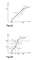
- this system is known. It leads to a braking law, curve 13 of the figure 2a , in which a force F1 applied by a conductor on the rod 9 resonates in a force F2 applied by the moving element to the hydraulic braking circuit 10.
- the curve 13 shown indicates that from a threshold force FD 1 braking assistance plays according to a linear correspondence 14. It also shows that from a force FS, called saturation force, the braking assistance produced by the pneumatic brake booster only correspondence 15, or because the movable partition 6 can no longer move towards the front chamber 1, either because it has reached the limit of this chamber, or rather because the rear chamber 3 is saturated at atmospheric pressure .
- the saturation force must be placed beyond a force Fb applied to the hydraulic circuit for which a locking of the wheels of the vehicle is caused.
- the value of the FD force is set by choices corresponding to a driver comfort, allowing him especially to put his foot on the brake pedal without braking.
- the slope of the assistance 14 for a conventional braking assistance pneumatic servomotor is linear and depends essentially on the ratio of the surfaces between a first surface corresponding to a face of a reaction disc and a second surface corresponding to the probe surface 11 in contact with the first surface.
- figure 2b shows the improvement brought by the invention.
- the curve of correspondence between the force applied by the and the force applied to the hydraulic circuit undergoes a first evolution 16 comparable to the evolution 14 of the curve 13.
- the mechanism of the invention causes additional assistance so that the slope of the assistance includes a segment 17 much higher.
- the saturation force FS 'encountered with the device of the invention is much lower than the saturation force FS of the conventional solution.
- the correspondence curve comprises a segment 18 similar to the segment 15. It will be seen later how it is possible to adjust the value of the intermediate force Fi.
- This setting leads to creating a segment 16 and a segment 17 or, in some cases, for example for sports cars, to offer, from the beginning, an assistance whose slope 19 is the same as that of the segment 17.
- a la Segments 16 and 17 encounter an inflection point 20 at which the assist force increases proportionally much more rapidly.
- the additional intake air mechanism added by the invention also has the effect of preventing the slope 17 from becoming infinite (in practice much too strong) in a vertical 21.
- the ratio of proportionality for segments 14 and 16 is of the order of four to six while it could reach a ratio greater than ten for segments 17 or 19.
- the figure 3a shows a sectional view of a half of a section of the second intake device, the control rod 9, the piston 22 and the reaction disk 23 of a servomotor of the invention.
- the piston 22 thus comprises a body formed by a piston rod 22.1 which opens out of the servomotor.
- the rod 22.1 is hollow and cylindrical.
- the rod 22.1 presses and drives by its base 22.2 the skirt 6.
- the rod 22.1 has an internal jacket 22.3 crimped on its inner wall.
- the jacket 22.3 slidably receives the reaction disc 23 carried by a plate or cup 24.
- the cup 24 is supported by a push rod 24.1 on a primary piston of a master cylinder (not shown).
- the cup 24, the disk 23 and the jacket 22.3 are circular cylindrical.
- the reaction disc 23 is thus contained by the jacket 22.3 of the pneumatic piston 22.
- On the disc 23 supports the 11.1 surface of the end of the probe 11 and the base of a circular cylindrical ring 22.4 crimped on the jacket 22.3 of the piston 22.
- the ring 22.4 is formed by two concentric circular cylindrical webs.
- the ring 22.4 is carried by the piston 22.
- the normal ratio of assistance force is that corresponding to the ratio of the bearing surfaces on the surface of the reaction disk 23 relative to the total surface of the reaction disk 23.
- a space 26 At the heart of the ring 22.4, in the invention, between the two sails, there is a space 26.
- This space 26 occupied at the base by a pellet 27 in contact with the reaction disk 23.
- the pellet 27 has a circular ring shape.
- the pellet 27 is subjected by its base to the contact of the reaction disk, to the swelling of the disc 23 when the latter undergoes the forces of the feeler 11 and the assistance ring 22.4 carried by the piston 22.
- a seat 25 of the probe 11 in which takes place the control rod 9 has a basin shape.
- the upper edge of this basin forms a valve 25.1 of the air intake valve 4.
- the valve 4 further comprises a seat 4.1.
- the seat 4.1 of the valve 4 receives the valve 25.1 in support.
- the seat 4.1 is rubber
- the valve 25.1 is steel.
- the control rod 9 is supported, via the seat 25 and the surface 11.1 of the feeler 11 on the reaction disk 23.
- the valve 25.1 of the seat 25 of the probe 11 loses contact with the seat 4.1 of the valve 4.
- the valve 4 opens, the air then enters the rear chamber 3 by this air inlet.
- This corresponding air supply has the effect of moving the partition 6 to the chamber 1.
- the piston 22 and in particular the ring 22.4 bears, in turn, on the reaction disc 23.
- the rod 22.1 of the body of the pneumatic piston is carried by the skirt 6.
- the rod 22.1 pushes the seat 4.1 against the valve 25.1.
- the flap closes.
- the assembly consisting of the control rod, the reaction disk and the thrust rod is then maintained in an equilibrium position.
- the vehicle brakes in correspondence of an available pressure in the master cylinder, itself proportional to the pressure experienced by the disc 23.
- the reaction disk offers a relief, opposite that of the cup 24, substantially flat.
- the ring 22.4 is secured to a cylindrical internal web 22.8 fixed to the ring 22.4, for example by bridges.
- This sail 22.8 also has, on the side of the axis of the control rod 9, a recess 22.9 in which a shoulder 39 bears from the feeler 11.
- a comfort set 40 separates the shoulder 39 from the recess at rest. 22.9.
- This game 40 allows the control rod 9 to act in the very first moments of braking by resting on the reaction disc 23 before the ring 22.4 and its inner portion 22.8 does the same during the translation of the pneumatic piston.
- the device of the invention comprises a rod, here hollow, circular cylindrical 28 and having arches allowing the bridges connecting the inner portion 22.8 of the ring 22.4 to the same ring 22.4.
- the rod 28 is supported by its base 28.1 on the face of the pellet 27 opposite that in contact with the reaction disc 23.
- the cane 28 has at its summit a crowning 28.2.
- the cap 28.2 abuts under another part 4.2 of the seat of the valve 4.
- the part 31 of the shirt 22.3 is surmounted by a bent portion 22.7.
- the cavity 29 encloses a coil spring 30.
- the spring 30 is in compression at one end under the curved portion 22.7 and at its other end by a boss 32. This boss 32 abuts a hook 33 of the jacket 22.3.
- the extrusion of the reaction disk 23 facing the pellet 27, from a certain braking force is such that it moves not only the pellet 27 and the probe 11 via its bearing surface 11.1 but, above all, it moves the end of the rod 28 in contact with the pellet 27.
- the rod 28, while compressing the spring 30, slides within the pneumatic piston body 22, and within the ring 22.4, until its cap 28.2 reaches the valve valve 4.
- This rod 28 then opens the valve 4 in large by pushing the seat 4.2 of the valve 4, even beyond the opening caused by the separation of the valve 25.1. Simplifying, everything happens as if the valve 25.1 was moving towards the disc 23, while the seat 4.2 (and 4.1 too) away.
- the opening of the valve becomes much larger than for the opening caused by the displacement of the control rod alone.
- the spring 30 is further constrained.
- the valve 4 opens all the while letting the air rush into the chamber 3 and thus providing additional pneumatic assistance.
- the adjustment of the stiffness of the spring 30 and the change in section of the abutment of the probe 11 via the surface 11.1 on the reaction disc 23 determine the effort Fi, from which operates the assistance ratio change.
- the determination of both the ratio of the sections and the adjustment of the spring 30 is necessary in addition to taking into account the plasticity of the material making up the reaction disk 23.
- the second point of inflection 20 of the curve of the figure 2b will intervene more or less late.
- the braking assistance law is governed according to section 17 of the curve of the figure 2b .
- the load of the spring must, on the other hand, correspond to a force Fi less than Fs saturation force for which the rear chamber 3 and front 1 are at the same pressure or for which the partition 6 is advanced to the maximum. This force Fs must always correspond to a force applied to the hydraulic circuit greater than that Fb for which a locking of the wheels of the vehicle occurs.
- the valve 4 is formed by a seal 4.3.
- the seat 4.1 (and 4.2) of the valve 4 is brought into contact with the valve 25.1 by the reaction action of the spring 22.6 which presses on the underside of the seal 4.3.
- the seal 4.3 of circular shape comprises two rails in elevation 4.4 and 4.5 in sealing and sliding against a sealed and cylindrical cap 34 crimped on the piston 22.
- the cap 34 also has two rails 35 and 36 which receive in sliding both rails 4.4 and 4.5. The sliding joint between the rail 4.5 and the rail 36 is sealed.
- the cap 35 bears on the spring 22.6 by means of a spring 35.1. This spring is in tension between the control rod 9 and an edge of the cap 35.
- the space 38 between the two rails is communicating with the suction space downstream of the valve 4 by one or more holes 37 which relate.
- the probe 11 comprises a shoulder 41 on which bears a washer 42 whose surface 42.1 is coplanar with the surface 11.1 of the probe 11 at the rest position of the booster.
- the washer 42 is placed around the probe and surrounded by the hollow rod 28.
- the spring 30 is placed as for him, in tension, between a 28.1 of the rod 28 and a redan 11.2 of the probe 11.
- the piston 22, a portion of which slides along and between the rod 28 and the probe 11 pushes the washer 42.
- Lights 44 and 45 respectively arranged in the piston 22 and the rod 28 allow the latter to slide along a part 46, fixed and on which abuts the step 11.2.
- the two surfaces 11.1 and 42.1 are then in contact with the reaction disk 23.
- the extrusion effect of the reaction disk 23 pushes, in a second step, both the probe 11 and the pellet 27.
- a clearance 43 between the piston and the pellet, along the rod 28 allows the rod to push and open the valve 4.
- the piston 22 is then pushed further and further support on the surfaces in contact with the reaction disc 23 and so that the surfaces 42.1 of the washer 42 and 11.1 of the probe 11 are, again, coplanar. In this case, the game 43 is caught up again.
- This braking phase then corresponds to the part 17 of the curve 18 of the figure 2b .
Landscapes
- Engineering & Computer Science (AREA)
- Transportation (AREA)
- Mechanical Engineering (AREA)
- Braking Systems And Boosters (AREA)
Applications Claiming Priority (1)
| Application Number | Priority Date | Filing Date | Title |
|---|---|---|---|
| FR0703601A FR2916408B1 (fr) | 2007-05-21 | 2007-05-21 | Servomoteur pneumatique d'assistance de freinage a changement de rapport d'assistance. |
Publications (3)
| Publication Number | Publication Date |
|---|---|
| EP1995141A2 true EP1995141A2 (de) | 2008-11-26 |
| EP1995141A3 EP1995141A3 (de) | 2014-04-09 |
| EP1995141B1 EP1995141B1 (de) | 2015-05-06 |
Family
ID=38917425
Family Applications (1)
| Application Number | Title | Priority Date | Filing Date |
|---|---|---|---|
| EP20080104010 Not-in-force EP1995141B1 (de) | 2007-05-21 | 2008-05-19 | Pneumatischer Bremskraftverstärker mit wechselndem Verstärkungsverhältnis |
Country Status (2)
| Country | Link |
|---|---|
| EP (1) | EP1995141B1 (de) |
| FR (1) | FR2916408B1 (de) |
Family Cites Families (3)
| Publication number | Priority date | Publication date | Assignee | Title |
|---|---|---|---|---|
| JPH11301457A (ja) * | 1998-04-15 | 1999-11-02 | Aisin Seiki Co Ltd | 負圧式倍力装置 |
| JP3956902B2 (ja) * | 2003-06-03 | 2007-08-08 | 株式会社アドヴィックス | 負圧式倍力装置 |
| JP4273931B2 (ja) * | 2003-11-04 | 2009-06-03 | 株式会社アドヴィックス | 負圧式倍力装置 |
-
2007
- 2007-05-21 FR FR0703601A patent/FR2916408B1/fr not_active Expired - Fee Related
-
2008
- 2008-05-19 EP EP20080104010 patent/EP1995141B1/de not_active Not-in-force
Non-Patent Citations (1)
| Title |
|---|
| None |
Also Published As
| Publication number | Publication date |
|---|---|
| EP1995141B1 (de) | 2015-05-06 |
| FR2916408A1 (fr) | 2008-11-28 |
| FR2916408B1 (fr) | 2009-12-18 |
| EP1995141A3 (de) | 2014-04-09 |
Similar Documents
| Publication | Publication Date | Title |
|---|---|---|
| WO1998003385A1 (fr) | Dispositif de freinage assiste a rapport d'assistance variable | |
| FR2998240A1 (fr) | Servofrein electrique | |
| FR2856363A1 (fr) | Servomoteur d'assistance pneumatique au freinage a course morte reduite et un systeme de freinage comportant un tel servomoteur. | |
| FR2795032A1 (fr) | Systeme de freins | |
| EP1995141B1 (de) | Pneumatischer Bremskraftverstärker mit wechselndem Verstärkungsverhältnis | |
| EP0779868B1 (de) | Bremsanlage mit erhöhter sicherheit | |
| EP1397279A1 (de) | Bremskraftverstärker mit zwei unterschiedlichen festen und veränderlichen schwellenwerten | |
| FR2771362A1 (fr) | Servofrein fonctionnant en frein automatique | |
| EP1343673B1 (de) | Unterstütztes bremssystem für kraftfahrzeug | |
| FR2838695A1 (fr) | Dispositif de commande de freinage a commande electrique adapte au freinage d'urgence | |
| EP0939715B1 (de) | Hilfskraftunterstütztes bremssystem mit verbesserter hydraulischer reaktion | |
| FR2940947A1 (fr) | Simulateur pour servofrein de vehicule comprenant une piece intermediaire | |
| FR2729354A1 (fr) | Dispositif de freinage assiste a course reduite | |
| FR2809066A1 (fr) | Servomoteur comportant un embrayage unidirectionnel expansible | |
| FR2765172A1 (fr) | Maitre-cylindre a reaction hydraulique dynamique reglee par une difference de sections | |
| EP1097073A1 (de) | Verbesserter hauptzylinder mit hydraulischer reaktion und selektiver selbstverstärkung | |
| EP1347909A1 (de) | Druckluftbremskraftverstärker mit verbesserter hilfskraft | |
| FR2908373A1 (fr) | Servomoteur d'assistance pneumatique au freinage | |
| WO2002102634A2 (fr) | Servomoteur d'assistance pneumatique au freinage a hauteur de saut variable. | |
| FR2867139A1 (fr) | Servomoteurs a deux sauts differencies par actionneur piezoelectrique | |
| EP1406801A1 (de) | Bremskraftverstärker mit differenzierten sprüngen | |
| WO2002094626A1 (fr) | Servomoteur d'assistance pneumatique au freinage a hauteur de saut variable | |
| FR2861036A1 (fr) | Systeme de freinage incluant un disque de reaction monte de maniere amelioree | |
| EP1343672A1 (de) | Pneumatischer bremskraftverstärker mit verbesserter bremscharakteristik | |
| FR2830058A1 (fr) | Dispositif amplificateur de pression pour circuit hydraulique |
Legal Events
| Date | Code | Title | Description |
|---|---|---|---|
| PUAI | Public reference made under article 153(3) epc to a published international application that has entered the european phase |
Free format text: ORIGINAL CODE: 0009012 |
|
| AK | Designated contracting states |
Kind code of ref document: A2 Designated state(s): AT BE BG CH CY CZ DE DK EE ES FI FR GB GR HR HU IE IS IT LI LT LU LV MC MT NL NO PL PT RO SE SI SK TR |
|
| AX | Request for extension of the european patent |
Extension state: AL BA MK RS |
|
| PUAL | Search report despatched |
Free format text: ORIGINAL CODE: 0009013 |
|
| AK | Designated contracting states |
Kind code of ref document: A3 Designated state(s): AT BE BG CH CY CZ DE DK EE ES FI FR GB GR HR HU IE IS IT LI LT LU LV MC MT NL NO PL PT RO SE SI SK TR |
|
| AX | Request for extension of the european patent |
Extension state: AL BA MK RS |
|
| RIC1 | Information provided on ipc code assigned before grant |
Ipc: B60T 13/575 20060101ALI20140304BHEP Ipc: B60T 13/57 20060101AFI20140304BHEP |
|
| 17P | Request for examination filed |
Effective date: 20141009 |
|
| RBV | Designated contracting states (corrected) |
Designated state(s): AT BE BG CH CY CZ DE DK EE ES FI FR GB GR HR HU IE IS IT LI LT LU LV MC MT NL NO PL PT RO SE SI SK TR |
|
| AKX | Designation fees paid |
Designated state(s): AT BE BG CH CY CZ DE DK EE ES FI FR GB GR HR HU IE IS IT LI LT LU LV MC MT NL NO PL PT RO SE SI SK TR |
|
| AXX | Extension fees paid |
Extension state: MK Extension state: BA Extension state: RS Extension state: AL |
|
| GRAP | Despatch of communication of intention to grant a patent |
Free format text: ORIGINAL CODE: EPIDOSNIGR1 |
|
| INTG | Intention to grant announced |
Effective date: 20150204 |
|
| GRAS | Grant fee paid |
Free format text: ORIGINAL CODE: EPIDOSNIGR3 |
|
| GRAA | (expected) grant |
Free format text: ORIGINAL CODE: 0009210 |
|
| AK | Designated contracting states |
Kind code of ref document: B1 Designated state(s): AT BE BG CH CY CZ DE DK EE ES FI FR GB GR HR HU IE IS IT LI LT LU LV MC MT NL NO PL PT RO SE SI SK TR |
|
| REG | Reference to a national code |
Ref country code: GB Ref legal event code: FG4D Free format text: NOT ENGLISH |
|
| REG | Reference to a national code |
Ref country code: CH Ref legal event code: EP |
|
| REG | Reference to a national code |
Ref country code: IE Ref legal event code: FG4D Free format text: LANGUAGE OF EP DOCUMENT: FRENCH |
|
| REG | Reference to a national code |
Ref country code: AT Ref legal event code: REF Ref document number: 725460 Country of ref document: AT Kind code of ref document: T Effective date: 20150615 |
|
| REG | Reference to a national code |
Ref country code: DE Ref legal event code: R096 Ref document number: 602008038013 Country of ref document: DE Effective date: 20150618 |
|
| REG | Reference to a national code |
Ref country code: AT Ref legal event code: MK05 Ref document number: 725460 Country of ref document: AT Kind code of ref document: T Effective date: 20150506 |
|
| REG | Reference to a national code |
Ref country code: NL Ref legal event code: MP Effective date: 20150506 |
|
| REG | Reference to a national code |
Ref country code: LT Ref legal event code: MG4D |
|
| PG25 | Lapsed in a contracting state [announced via postgrant information from national office to epo] |
Ref country code: ES Free format text: LAPSE BECAUSE OF FAILURE TO SUBMIT A TRANSLATION OF THE DESCRIPTION OR TO PAY THE FEE WITHIN THE PRESCRIBED TIME-LIMIT Effective date: 20150506 Ref country code: HR Free format text: LAPSE BECAUSE OF FAILURE TO SUBMIT A TRANSLATION OF THE DESCRIPTION OR TO PAY THE FEE WITHIN THE PRESCRIBED TIME-LIMIT Effective date: 20150506 Ref country code: PT Free format text: LAPSE BECAUSE OF FAILURE TO SUBMIT A TRANSLATION OF THE DESCRIPTION OR TO PAY THE FEE WITHIN THE PRESCRIBED TIME-LIMIT Effective date: 20150907 Ref country code: LT Free format text: LAPSE BECAUSE OF FAILURE TO SUBMIT A TRANSLATION OF THE DESCRIPTION OR TO PAY THE FEE WITHIN THE PRESCRIBED TIME-LIMIT Effective date: 20150506 Ref country code: NO Free format text: LAPSE BECAUSE OF FAILURE TO SUBMIT A TRANSLATION OF THE DESCRIPTION OR TO PAY THE FEE WITHIN THE PRESCRIBED TIME-LIMIT Effective date: 20150806 Ref country code: FI Free format text: LAPSE BECAUSE OF FAILURE TO SUBMIT A TRANSLATION OF THE DESCRIPTION OR TO PAY THE FEE WITHIN THE PRESCRIBED TIME-LIMIT Effective date: 20150506 |
|
| PGFP | Annual fee paid to national office [announced via postgrant information from national office to epo] |
Ref country code: DE Payment date: 20150723 Year of fee payment: 8 |
|
| PG25 | Lapsed in a contracting state [announced via postgrant information from national office to epo] |
Ref country code: IS Free format text: LAPSE BECAUSE OF FAILURE TO SUBMIT A TRANSLATION OF THE DESCRIPTION OR TO PAY THE FEE WITHIN THE PRESCRIBED TIME-LIMIT Effective date: 20150906 Ref country code: AT Free format text: LAPSE BECAUSE OF FAILURE TO SUBMIT A TRANSLATION OF THE DESCRIPTION OR TO PAY THE FEE WITHIN THE PRESCRIBED TIME-LIMIT Effective date: 20150506 Ref country code: LV Free format text: LAPSE BECAUSE OF FAILURE TO SUBMIT A TRANSLATION OF THE DESCRIPTION OR TO PAY THE FEE WITHIN THE PRESCRIBED TIME-LIMIT Effective date: 20150506 Ref country code: GR Free format text: LAPSE BECAUSE OF FAILURE TO SUBMIT A TRANSLATION OF THE DESCRIPTION OR TO PAY THE FEE WITHIN THE PRESCRIBED TIME-LIMIT Effective date: 20150807 Ref country code: BG Free format text: LAPSE BECAUSE OF FAILURE TO SUBMIT A TRANSLATION OF THE DESCRIPTION OR TO PAY THE FEE WITHIN THE PRESCRIBED TIME-LIMIT Effective date: 20150806 |
|
| REG | Reference to a national code |
Ref country code: CH Ref legal event code: PL |
|
| PG25 | Lapsed in a contracting state [announced via postgrant information from national office to epo] |
Ref country code: IT Free format text: LAPSE BECAUSE OF FAILURE TO SUBMIT A TRANSLATION OF THE DESCRIPTION OR TO PAY THE FEE WITHIN THE PRESCRIBED TIME-LIMIT Effective date: 20150506 Ref country code: LI Free format text: LAPSE BECAUSE OF NON-PAYMENT OF DUE FEES Effective date: 20150531 Ref country code: DK Free format text: LAPSE BECAUSE OF FAILURE TO SUBMIT A TRANSLATION OF THE DESCRIPTION OR TO PAY THE FEE WITHIN THE PRESCRIBED TIME-LIMIT Effective date: 20150506 Ref country code: EE Free format text: LAPSE BECAUSE OF FAILURE TO SUBMIT A TRANSLATION OF THE DESCRIPTION OR TO PAY THE FEE WITHIN THE PRESCRIBED TIME-LIMIT Effective date: 20150506 Ref country code: CH Free format text: LAPSE BECAUSE OF NON-PAYMENT OF DUE FEES Effective date: 20150531 |
|
| REG | Reference to a national code |
Ref country code: DE Ref legal event code: R097 Ref document number: 602008038013 Country of ref document: DE |
|
| REG | Reference to a national code |
Ref country code: IE Ref legal event code: MM4A |
|
| PG25 | Lapsed in a contracting state [announced via postgrant information from national office to epo] |
Ref country code: CZ Free format text: LAPSE BECAUSE OF FAILURE TO SUBMIT A TRANSLATION OF THE DESCRIPTION OR TO PAY THE FEE WITHIN THE PRESCRIBED TIME-LIMIT Effective date: 20150506 Ref country code: RO Free format text: LAPSE BECAUSE OF NON-PAYMENT OF DUE FEES Effective date: 20150506 Ref country code: PL Free format text: LAPSE BECAUSE OF FAILURE TO SUBMIT A TRANSLATION OF THE DESCRIPTION OR TO PAY THE FEE WITHIN THE PRESCRIBED TIME-LIMIT Effective date: 20150506 Ref country code: MC Free format text: LAPSE BECAUSE OF FAILURE TO SUBMIT A TRANSLATION OF THE DESCRIPTION OR TO PAY THE FEE WITHIN THE PRESCRIBED TIME-LIMIT Effective date: 20150506 Ref country code: SK Free format text: LAPSE BECAUSE OF FAILURE TO SUBMIT A TRANSLATION OF THE DESCRIPTION OR TO PAY THE FEE WITHIN THE PRESCRIBED TIME-LIMIT Effective date: 20150506 |
|
| PLBE | No opposition filed within time limit |
Free format text: ORIGINAL CODE: 0009261 |
|
| STAA | Information on the status of an ep patent application or granted ep patent |
Free format text: STATUS: NO OPPOSITION FILED WITHIN TIME LIMIT |
|
| 26N | No opposition filed |
Effective date: 20160209 |
|
| GBPC | Gb: european patent ceased through non-payment of renewal fee |
Effective date: 20150806 |
|
| PG25 | Lapsed in a contracting state [announced via postgrant information from national office to epo] |
Ref country code: IE Free format text: LAPSE BECAUSE OF NON-PAYMENT OF DUE FEES Effective date: 20150519 |
|
| REG | Reference to a national code |
Ref country code: FR Ref legal event code: PLFP Year of fee payment: 9 |
|
| PG25 | Lapsed in a contracting state [announced via postgrant information from national office to epo] |
Ref country code: SI Free format text: LAPSE BECAUSE OF FAILURE TO SUBMIT A TRANSLATION OF THE DESCRIPTION OR TO PAY THE FEE WITHIN THE PRESCRIBED TIME-LIMIT Effective date: 20150506 |
|
| PG25 | Lapsed in a contracting state [announced via postgrant information from national office to epo] |
Ref country code: GB Free format text: LAPSE BECAUSE OF NON-PAYMENT OF DUE FEES Effective date: 20150806 |
|
| PGFP | Annual fee paid to national office [announced via postgrant information from national office to epo] |
Ref country code: FR Payment date: 20160523 Year of fee payment: 9 |
|
| REG | Reference to a national code |
Ref country code: DE Ref legal event code: R119 Ref document number: 602008038013 Country of ref document: DE |
|
| PG25 | Lapsed in a contracting state [announced via postgrant information from national office to epo] |
Ref country code: MT Free format text: LAPSE BECAUSE OF FAILURE TO SUBMIT A TRANSLATION OF THE DESCRIPTION OR TO PAY THE FEE WITHIN THE PRESCRIBED TIME-LIMIT Effective date: 20150506 |
|
| PG25 | Lapsed in a contracting state [announced via postgrant information from national office to epo] |
Ref country code: DE Free format text: LAPSE BECAUSE OF NON-PAYMENT OF DUE FEES Effective date: 20161201 |
|
| PG25 | Lapsed in a contracting state [announced via postgrant information from national office to epo] |
Ref country code: HU Free format text: LAPSE BECAUSE OF FAILURE TO SUBMIT A TRANSLATION OF THE DESCRIPTION OR TO PAY THE FEE WITHIN THE PRESCRIBED TIME-LIMIT; INVALID AB INITIO Effective date: 20080519 |
|
| PG25 | Lapsed in a contracting state [announced via postgrant information from national office to epo] |
Ref country code: SE Free format text: LAPSE BECAUSE OF FAILURE TO SUBMIT A TRANSLATION OF THE DESCRIPTION OR TO PAY THE FEE WITHIN THE PRESCRIBED TIME-LIMIT Effective date: 20150506 Ref country code: NL Free format text: LAPSE BECAUSE OF FAILURE TO SUBMIT A TRANSLATION OF THE DESCRIPTION OR TO PAY THE FEE WITHIN THE PRESCRIBED TIME-LIMIT Effective date: 20150506 Ref country code: CY Free format text: LAPSE BECAUSE OF FAILURE TO SUBMIT A TRANSLATION OF THE DESCRIPTION OR TO PAY THE FEE WITHIN THE PRESCRIBED TIME-LIMIT Effective date: 20150506 |
|
| PG25 | Lapsed in a contracting state [announced via postgrant information from national office to epo] |
Ref country code: BE Free format text: LAPSE BECAUSE OF NON-PAYMENT OF DUE FEES Effective date: 20150531 |
|
| PG25 | Lapsed in a contracting state [announced via postgrant information from national office to epo] |
Ref country code: TR Free format text: LAPSE BECAUSE OF FAILURE TO SUBMIT A TRANSLATION OF THE DESCRIPTION OR TO PAY THE FEE WITHIN THE PRESCRIBED TIME-LIMIT Effective date: 20150506 |
|
| PG25 | Lapsed in a contracting state [announced via postgrant information from national office to epo] |
Ref country code: LU Free format text: LAPSE BECAUSE OF NON-PAYMENT OF DUE FEES Effective date: 20150519 |
|
| REG | Reference to a national code |
Ref country code: FR Ref legal event code: ST Effective date: 20180131 |
|
| PG25 | Lapsed in a contracting state [announced via postgrant information from national office to epo] |
Ref country code: FR Free format text: LAPSE BECAUSE OF NON-PAYMENT OF DUE FEES Effective date: 20170531 |