EP1994808B1 - Torche a plasma a arc transfere - Google Patents
Torche a plasma a arc transfere Download PDFInfo
- Publication number
- EP1994808B1 EP1994808B1 EP07726439.8A EP07726439A EP1994808B1 EP 1994808 B1 EP1994808 B1 EP 1994808B1 EP 07726439 A EP07726439 A EP 07726439A EP 1994808 B1 EP1994808 B1 EP 1994808B1
- Authority
- EP
- European Patent Office
- Prior art keywords
- electrode
- torch
- gas
- sheath
- plasma
- Prior art date
- Legal status (The legal status is an assumption and is not a legal conclusion. Google has not performed a legal analysis and makes no representation as to the accuracy of the status listed.)
- Active
Links
Images

Classifications
-
- H—ELECTRICITY
- H05—ELECTRIC TECHNIQUES NOT OTHERWISE PROVIDED FOR
- H05H—PLASMA TECHNIQUE; PRODUCTION OF ACCELERATED ELECTRICALLY-CHARGED PARTICLES OR OF NEUTRONS; PRODUCTION OR ACCELERATION OF NEUTRAL MOLECULAR OR ATOMIC BEAMS
- H05H1/00—Generating plasma; Handling plasma
- H05H1/24—Generating plasma
- H05H1/26—Plasma torches
- H05H1/32—Plasma torches using an arc
- H05H1/34—Details, e.g. electrodes, nozzles
- H05H1/3421—Transferred arc or pilot arc mode
-
- B—PERFORMING OPERATIONS; TRANSPORTING
- B05—SPRAYING OR ATOMISING IN GENERAL; APPLYING FLUENT MATERIALS TO SURFACES, IN GENERAL
- B05B—SPRAYING APPARATUS; ATOMISING APPARATUS; NOZZLES
- B05B7/00—Spraying apparatus for discharge of liquids or other fluent materials from two or more sources, e.g. of liquid and air, of powder and gas
- B05B7/16—Spraying apparatus for discharge of liquids or other fluent materials from two or more sources, e.g. of liquid and air, of powder and gas incorporating means for heating or cooling the material to be sprayed
- B05B7/22—Spraying apparatus for discharge of liquids or other fluent materials from two or more sources, e.g. of liquid and air, of powder and gas incorporating means for heating or cooling the material to be sprayed electrically, magnetically or electromagnetically, e.g. by arc
- B05B7/222—Spraying apparatus for discharge of liquids or other fluent materials from two or more sources, e.g. of liquid and air, of powder and gas incorporating means for heating or cooling the material to be sprayed electrically, magnetically or electromagnetically, e.g. by arc using an arc
- B05B7/224—Spraying apparatus for discharge of liquids or other fluent materials from two or more sources, e.g. of liquid and air, of powder and gas incorporating means for heating or cooling the material to be sprayed electrically, magnetically or electromagnetically, e.g. by arc using an arc the material having originally the shape of a wire, rod or the like
-
- H—ELECTRICITY
- H05—ELECTRIC TECHNIQUES NOT OTHERWISE PROVIDED FOR
- H05H—PLASMA TECHNIQUE; PRODUCTION OF ACCELERATED ELECTRICALLY-CHARGED PARTICLES OR OF NEUTRONS; PRODUCTION OR ACCELERATION OF NEUTRAL MOLECULAR OR ATOMIC BEAMS
- H05H1/00—Generating plasma; Handling plasma
- H05H1/24—Generating plasma
- H05H1/26—Plasma torches
- H05H1/32—Plasma torches using an arc
- H05H1/34—Details, e.g. electrodes, nozzles
- H05H1/3425—Melting or consuming electrodes
Definitions
- the present invention relates to the field of plasma torches and more particularly plasma torches transferred arc.
- Plasma torches are used for the treatment of matter (solid, liquid or gas) at a very high temperature in an atmosphere of controlled reactivity. Plasma torches are typically used in welding, marking, thermal spraying and waste treatment.
- Plasma is a gas in the ionized state, classically considered as a fourth state of matter.
- plasma torches are used. These provide the necessary energy for the ionization of the gas by means of an electromagnetic wave (radio frequency or microwave) or an electric arc. We will consider here only the arc torches that are the only technology to achieve significant operating power.
- Arc torches are classified into two categories: blown arc torches and transferred arc torches.
- the two electrodes for the establishment of the arc are contained in the torch and the arc is therefore confined inside thereof.
- Plasma plume created by the passage of a gas in the arc is ejected outside the torch.
- the torch comprises only one electrode and the arc is established between the torch and another material acting as a counterelectrode. Examples of blown-arc and transferred-arc torches are described in the application EP-A-706308 .
- Two transferred arc torches can be used in a paired fashion to maintain an arc between them, one serving as a cathode and the other anode.
- This device is known as bipolar twin torches or "twin torches”.
- twin torches An example of twin torches is described in the application EP-A-1281296 .
- the so-called “hot” electrodes made of refractory material with a high boiling or sublimation point, such as tungsten and zirconium
- so-called “cold” electrodes made of low-point material. boiling and with high thermal conductivity like copper. Whatever the type of material used, the electrode undergoes erosion wear.
- the document US Patent 4146772 relates to a plasma-MIG sounding device in which the electrode establishing the electric arc is non-consumable and the sounding wire is consumable.
- the object of the present invention is to have a transferred arc plasma torch having the same utilization properties as cooled electrode plasma torches but without presenting the disadvantages thereof, in particular in terms of size and complexity. mounting and maintenance.
- the present invention is defined as a transferred arc plasma torch comprising a sleeve cooled by a cooling fluid and an electrode inserted in said sleeve, wherein said electrode, intended to establish an electric arc in a plasmagene gas in cooperation with a counter electrode, is made of a consumable material and the torch comprises means for supplying the electrode of this material so as to compensate for its erosion.
- the means for supplying the material electrode comprise means for automatically feeding the electrode towards the distal end of the torch.
- the means for supplying the material electrode comprise means for automatically feeding the electrode towards the distal end of the torch.
- the torch comprises gaseous cladding means ensuring the cladding of said electrode by a neutral gas and plasmagene inside said sheath.
- the gaseous cladding means ensure the scanning of the electrode by said gas and its diffusion at the distal end of the electrode.
- the sheath may comprise conduits for supplying a secondary gas at its distal end, the torch comprising injection means connected to said supply ducts for injecting a gas secondary downstream of the electrode.
- the plasma torch comprises a fixed torch body supporting all of the gas connections, the cooling fluid and the power supply.
- the sheath has a tubular portion secured to a torch head and passes therethrough, the torch head resting on said torch body and cooperating with it to ensure the continuity of the gas, cooling fluid and gas flow circuits. power supply between said connectors and said sleeve.
- the tubular portion of the sheath comprises two concentric shells delimiting a cavity connected to the cooling circuit.
- a guiding and holding device may be provided so as to position the torch head on said body in a predetermined position and fix it to said body in this position. The assembly and disassembly will be facilitated and in particular one will avoid sealing problems resulting from a misalignment between the body and the torch head.
- the power supply of the electrode is ensured by means of at least one metal broom mounted on the head of the torch and pressing on the surface of the electrode by the action of a spring. Again, the assembly and disassembly of the electrode will be facilitated.
- a first idea underlying the invention is to provide a consumable electrode fed continuously material.
- a second idea underlying the invention is to protect this electrode by a sheath of neutral gas in the sheath.
- the invention will advantageously be used for producing twin plasma torches, one serving as anode and the other as a cathode. However, these two torches being structurally identical, only one will be described.
- the Fig. 1 represents a transferred arc plasma torch according to the invention. It comprises a support 10 referred to as a torch body, a sheath 25, preferably metal, having a tubular portion integral at its upper part with a torch head 20, a consumable electrode 30, for example a graphite electrode, a guiding device and 40, a diffuser 50, a device for advancing the electrode 60, means for electrical connection to the brush electrode 70.
- the torch body 10 constitutes the fixed part of the torch which is never disassembled and supports all the connection with the fluid circuits, gas and power supply.
- the connections are the arrival and departure of cooling water from the head and sheath, the arrival of plasma gas, the secondary gas supply and the power supply.
- the torch body comprises in its upper part a plate 11 which open the gas circuits, cooling fluid and electrical connections.
- the torch head 20 is mounted on the plate 11 of the torch body by means of a guiding and holding device 40.
- This device ensures guiding and fixing of the torch head on the torch body in a predetermined position. Guiding is provided by a guiding pin or a centering device on the support body or a combination of these means. The maintenance is for example achieved by means of a quick fastening mechanism.
- the continuity of the fluid and gas circuits between the support body 10 and the torch head 20 is provided by systems suitable seals, for example by means of seals, in particular O-rings, or by means of special connections at the plate 11.
- the graphite cylindrical electrode 30 passes right through the torch head and extends into the sheath. Its power supply is performed by a metal brush contact 70 pushed on the electrode by a spring 71. Means are provided to allow the supply of the electrode consumable material, for example by means of automatic advance placed at the level of the torch head. These means of advance are for example motorized rollers 60 with adjustable speed, coming to rest on the electrode, in diametrically opposite positions and advancing the electrode by friction towards the distal end of the torch.
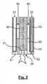
- the Fig. 2 describes more precisely the end of the torch head according to the invention.
- the electrode 30 is protected by the sheath 25 and the torch head 20.
- the distal end 31 of the electrode is advantageously set back from the nose 26 of the torch.
- the sheath is cooled by internal circulation of a cooling fluid 21, for example water.
- the sleeve has a tubular shape with two concentric envelopes, the cooling fluid circulating in the cavity defined by these two envelopes.
- conduits 22 disposed inside the cavity allow the supply of the secondary gas 23 to the distal end of the torch.
- the plasma torch comprises gaseous cladding means adapted to maintain a neutral and protective gas sheath around the electrode.
- This neutral gas is also used to generate the plasma.
- the gaseous cladding means ensure not only the scanning of the electrode by the neutral gas but also the diffusion of this gas at its istale or active end. Thus the electrode is protected from the external environment, especially if it is oxidizing.
- the gas cladding means comprise the gas supply circuit and the diffuser 50.
- the latter fulfills several functions: in addition to the circulation of the plasmagenic neutral gas 80 between the electrode 30 and the sheath 25 and its diffusion at the active end of the electrode, it ensures the coaxial centering of the electrode 30 relative to the sheath 25 and their mutual electrical insulation.
- the diffuser 50 may be in the form of an insulating ring provided with a flange 51 at its lower part.
- the insulating ring is held in the sleeve 25 by a metal stop ring or equivalent clipping system.
- the inner diameter of the ring is chosen so as to maintain the sheath slightly overpressure and ensure the scanning of the electrode 30, by the neutral gas and plasmagene.
- the flange is traversed by nozzles 52 fed by the supply pipe or pipes 22 of the secondary gas so that the secondary gas is injected into the plasma zone downstream of the electrode.
- the plasma gas allows the creation of a plasma with a stable arc while the secondary gas makes it possible to obtain a plasma having the desired chemical composition or physical properties.
- argagene and oxygen secondary gas will be used as plasma neutral gas.
- Such a system can be used in all applications requiring the generation of a plasma and in particular in the field of waste treatment.
Landscapes
- Physics & Mathematics (AREA)
- Engineering & Computer Science (AREA)
- Plasma & Fusion (AREA)
- Spectroscopy & Molecular Physics (AREA)
- Electromagnetism (AREA)
- Plasma Technology (AREA)
- Arc Welding In General (AREA)
Description
- La présente invention concerne le domaine des torches à plasma et plus particulièrement des torches à plasma à arc transféré.
- Les torches à plasma sont utilisées pour le traitement de matière (solide, liquide ou gaz) à très haute température en atmosphère de réactivité contrôlée. Les torches à plasma trouvent classiquement application en particulier dans le soudage, le marquage, la projection thermique et le traitement des déchets.
- Le plasma est un gaz à l'état ionisé, classiquement considéré comme un quatrième état de la matière. Pour obtenir l'ionisation d'un gaz à la pression atmosphérique, on utilise des torches à plasma. Celles-ci apportent l'énergie nécessaire à l'ionisation du gaz au moyen d'une onde électromagnétique (radio fréquence ou micro onde) ou d'un arc électrique. Nous ne considérerons ici que les torches à arc qui constituent la seule technologie permettant d'atteindre des puissances de fonctionnement importantes.
- On classe les torches à arc en deux catégories : les torches à arc soufflé et les torches à arc transféré. Dans le cas des torches à arc soufflé, les deux électrodes permettant l'établissement de l'arc sont contenues dans la torche et l'arc est donc confiné à l'intérieur de celle-ci. Le panache de.plasma créé par le passage d'un gaz dans l'arc est éjecté à l'extérieur de la torche. Dans le cas des torches à arc transféré, la torche ne comprend qu'une seule électrode et l'arc s'établit entre la torche et un autre matériau faisant office de contre-électrode. Des exemples de torches à arc soufflé et à arc transféré sont décrits dans la demande
EP-A-706308 - Deux torches à arc transféré peuvent être utilisées de façon jumelée afin d'entretenir un arc entre elles, l'une faisant office de cathode et l'autre d'anode. Ce dispositif est connu sous le nom de torches jumelées bipolaires ou « twin torches ».
- Un exemple de torches jumelées est décrit dans la demande
EP-A-1281296 . - Quelle que soit la technologie de torche à arc mise en oeuvre, le problème principal demeure la faible durée de vie des électrodes.
- Depuis plusieurs années, de nombreux travaux de recherche ont essentiellement porté sur l'amélioration de la durée de vie des électrodes des torches à plasma par le choix du matériau des électrodes. Ces dernières sont classées en deux catégories : les électrodes dites « chaudes », réalisées en matériau réfractaire à haut point d'ébullition ou de sublimation tel le tungstène et le zirconium et les électrodes dites « froides », réalisées en matériau à bas point d'ébullition et à forte conductivité thermique comme le cuivre. Quel que soit le type de matériau utilisé, l'électrode subit une usure par érosion.
- Différentes solutions technologiques ont été mises au point pour diminuer la vitesse d'usure des électrodes : dopage du tungstène au thorium, usinage de l'extrémité de l'électrode etc. La nécessité de refroidir l'électrode elle-même par circulation interne d'eau est rapidement apparue et a eu pour principale conséquence de rendre plus complexe l'architecture des torches, la présence de deux voire trois circuits de refroidissement distincts n'étant guère compatible avec des systèmes de taille limitée comme les torches à plasma thermique. En outre, les opérations de maintenance et de remplacement des électrodes sont rendues malaisées par la nécessité de déconnecter préalablement les raccords des circuits de refroidissement.
- Il est par ailleurs connu dans un domaine éloigné de celui des torches à plasma, à savoir celui de l'électrolyse de l'aluminium ou de la sidérurgie d',utiliser des électrodes consommables, se présentant sous la forme d'un simple cylindre massif en graphite. Cependant, les seules applications possibles de ces électrodes sont en atmosphère gazeuse plutôt réductrice car en atmosphère oxydante, la combustion du graphite entraînerait une érosion rapide de celles-ci.
- Le document
US-A-4146772 concerne un dispositif de sondage de type plasma-MIG dans lequel l'electrode établissant l'arc électrique est non-consommable et le fil de sondure est consommable. - Le but de la présente invention est de disposer d'une torche à plasma à arc transféré ayant les mêmes propriétés d'utilisation que les torches à plasma à électrodes refroidies mais sans en présenter les désavantages, notamment en termes d'encombrement et de complexité de montage et de maintenance.
- La présente invention est définie comme une torche à plasma à arc transféré comportant un fourreau refroidi au moyen d'un fluide de refroidissement et une électrode insérée dans ledit fourreau, dans laquelle ladite électrode, destinée à établir un arc électrique dans un gaz plasmagène en coopération avec une contre-électrode, est réalisée dans un matériau consommable et la torche comprend des moyens pour alimenter l'électrode en ce matériau de façon à compenser son érosion.
- Ainsi il n'est pas nécessaire de prévoir un circuit de refroidissement supplémentaire pour refroidir l'électrode.
- Selon un mode de réalisation, les moyens pour alimenter l'électrode en matériau comprennent des moyens d'avance automatique de l'électrode vers l'extrémité distale de la torche. On pourra notamment prévoir des galets faisant avancer par friction l'électrode vers l'extrémité distale de la torche.
- Avantageusement, la torche comprend des moyens de gainage gazeux assurant le gainage de ladite électrode par un gaz neutre et plasmagène à l'intérieur dudit fourreau.
- Ainsi l'érosion de l'électrode sera considérablement freinée et sa durée de vie prolongée. De manière à optimiser la protection, les moyens de gainage gazeux assurent le balayage de l'électrode par ledit gaz et sa diffusion à l'extrémité distale de l'électrode.
- Le fourreau pourra comprendre des conduits d'amenée d'un gaz secondaire à son extrémité distale, la torche comportant des moyens d'injection connectés aux dits conduits d'amenée pour injecter un gaz secondaire en aval de l'électrode. Cet arrangement compact permet d'obtenir un plasma de la composition souhaitée en aval de l'électrode.
- Avantageusement, la torche à plasma comprend un corps de torche fixe supportant l'ensemble des raccords des gaz, du fluide de refroidissement et de l'alimentation électrique. Le fourreau présente une partie tubulaire solidaire d'une tête de torche et la traverse de part en part, la tête de torche reposant sur ledit corps de torche et coopérant avec lui pour assurer la continuité des circuits de gaz, de fluide de refroidissement et d'alimentation électrique entre lesdits raccords et ledit fourreau.
- Ainsi, il n'est pas nécessaire de démonter les raccords de gaz, de fluide de refroidissement et d'alimentation électrique lors d'un changement d'électrode.
- Typiquement, la partie tubulaire du fourreau comprend deux enveloppes concentriques délimitant une cavité reliée au circuit de refroidissement.
- En outre, un dispositif de guidage et de maintien peut être prévu de manière à positionner la tête de torche sur ledit corps dans une position prédéterminée et la fixer au dit corps dans cette position. Le montage et le démontage s'en trouveront facilités et l'on évitera notamment des problèmes d'étanchéité résultant d'un défaut d'alignement entre le corps et la tête de torche.
- L'alimentation électrique de l'électrode est assurée au moyen d'au moins un balai métallique monté sur la tête de la torche et appuyant sur la surface de l'électrode par l'action d'un ressort. Là encore, le montage et le démontage de l'électrode s'en trouveront facilités.
- D'autres caractéristiques et avantages de l'invention apparaîtront à la lecture d'un mode de réalisation préférentiel de l'invention fait en référence aux figures jointes parmi lesquelles :
- La
Fig. 1 représente schématiquement une torche à plasma à arc transféré selon l'invention ; - La
Fig. 2 représente un détail d'une torche à plasma à arc transféré selon l'invention. - Une première idée à la base de l'invention est de prévoir une électrode consommable alimentée en continu en matériau. Une seconde idée à la base de l'invention est de protéger cette électrode par un gainage de gaz neutre dans le fourreau.
- L'invention sera avantageusement utilisée pour la réalisation de torches à plasma jumelées, l'une faisant office d'anode et l'autre de cathode. Toutefois, ces deux torches étant structurellement identiques, une seule sera décrite.
- La
Fig. 1 représente une torche à plasma à arc transféré selon l'invention. Elle comprend un support 10 dit corps de torche, un fourreau 25, préférentiellement métallique, présentant une partie tubulaire solidaire en sa partie supérieure d'une tête de torche 20, une électrode consommable 30 par exemple une électrode en graphite, un dispositif de guidage et de maintien 40, un diffuseur 50, un dispositif d'avance de l'électrode 60, des moyens de connexion électrique à l'électrode par balai 70. - Le corps de torche 10 constitue la partie fixe de la torche qui n'est jamais démontée et supporte toute la connectique avec les circuits fluides, gaz et alimentation. Les raccords sont l'arrivée et le départ en eau de refroidissement de la tête et du fourreau, l'arrivée de gaz plasmagène, l'arrivée de gaz secondaire et de l'alimentation électrique. Le corps de torche comporte en sa partie supérieure une platine 11 où débouchent les circuits de gaz, de fluide de refroidissement et les connections électriques.
- La tête de torche 20 est montée sur la platine 11 du corps de torche au moyen d'un dispositif de guidage et maintien 40. Ce dispositif assure le guidage et la fixation de la tête de torche sur le corps de torche dans une position prédéterminée. Le guidage est assuré par un pion de guidage ou un dispositif de centrage sur le corps support ou une combinaison de ces moyens. Le maintien est par exemple réalisé au moyen d'un mécanisme de fixation rapide. La continuité des circuits de fluide et de gaz entre le corps support 10 et la tête de torche 20 est assurée par des systèmes étanches appropriés, par exemple au moyen de joints, en particulier de joints toriques, ou bien au moyen de raccords spéciaux au niveau de la platine 11.
- L'électrode cylindrique 30 en graphite traverse de part en part la tête de torche et se prolonge dans le fourreau. Son alimentation électrique est réalisée par un contact à balai métallique 70 poussé sur l'électrode par un ressort 71. Des moyens sont prévus pour permettre l'alimentation de l'électrode en matériau consommable, par exemple grâce à des moyens d'avance automatique placé au niveau de la tête de torche. Ces moyens d'avance sont par exemple des galets motorisés 60 à vitesse réglable, venant s'appuyer sur l'électrode, en des endroits diamétralement opposés et faisant progresser l'électrode par friction vers l'extrémité distale de la torche.
- De cette manière, lorsque la tête de torche doit être démontée, seul le système de maintien 40 est à manipuler, ce qui permet de libérer la tête de torche 20 du corpus de torche 10, simplement en la soulevant verticalement de la platine. On voit ici l'intérêt de pouvoir désolidariser toute la partie mécanique de la torche sans avoir à déconnecter les circuits de fluides et gaz du corps de torche 10.
- La
Fig. 2 décrit de manière plus précise l'extrémité de la tête de torche selon l'invention. - Comme indiqué précédemment, l'électrode 30 est protégée par le fourreau 25 et la tête de torche 20. L'extrémité distale 31 de l'électrode est avantageusement située en retrait par rapport au nez 26 de la torche. Le fourreau est refroidi par circulation interne d'un fluide de refroidissement 21 par exemple d'eau. Le fourreau présente une forme tubulaire à deux enveloppes concentriques, le fluide de refroidissement circulant dans la cavité délimitée par ces deux enveloppes. En outre, des conduits 22 disposés à l'intérieur de la cavité permettent l'amenée du gaz secondaire 23 jusqu'à l'extrémité distale de la torche.
- La torche à plasma comprend des moyens de gainage gazeux adaptés à maintenir une gaine de gaz neutre et protecteur autour de l'électrode. Ce gaz neutre est également utilisé pour générer le plasma. Plus précisément, les moyens de gainage gazeux assurent non seulement le balayage de l'électrode par le gaz neutre mais aussi la diffusion de ce gaz à son extrémité d'istale ou active. Ainsi l'électrode est protégée de l'environnement extérieur, notamment s'il est oxydant.
- Les moyens de gainage gazeux comprennent le circuit d'alimentation en gaz et le diffuseur 50. En fait, ce dernier remplit plusieurs fonctions : outre la circulation du gaz neutre plasmagène 80 entre l'électrode 30 et le fourreau 25 et sa diffusion à l'extrémité active de l'électrode, il assure le centrage coaxial de l'électrode 30 par rapport au fourreau 25 ainsi que leur isolation électrique mutuelle. Le diffuseur 50 peut se présenter sous la forme d'une bague isolante pourvue d'une bride 51 à sa partie inférieure. La bague isolante est maintenue dans le fourreau 25 par un jonc métallique d'arrêt ou tout système de clipsage équivalent. Le diamètre intérieur de la bague est choisi de manière à maintenir le fourreau en légère surpression et à assurer le balayage de l'électrode 30, par le gaz neutre et plasmagène. En outre, la bride est traversée par des buses 52 alimentées par le ou les tuyaux d'amenée 22 du gaz secondaire de sorte que le gaz secondaire est injecté dans la zone de plasma en aval de l'électrode.
- Il convient de noter que le gaz plasmagène permet la création d'un plasma avec un arc stable alors que le gaz secondaire permet d'obtenir un plasma possédant la composition chimique ou les propriétés physiques recherchées. Avantageusement, on utilisera comme gaz neutre plasmagène de l'argon et comme gaz secondaire de l'oxygène.
- Un tel système peut être utilisé dans toutes les applications nécessitant la génération d'un plasma et notamment dans le domaine du traitement de déchets.
Claims (10)
- Torche à plasma à arc transféré comportant un fourreau (25) refroidi au moyen d'un fluide de refroidissement (21) et une électrode (30) insérée dans ledit fourreau, caractérisée en ce que ladite électrode, destinée à établir un arc électrique dans un gaz plasmagène en coopération avec une contre-électrode, est réalisée dans un matériau consommable et que la torche comprend des moyens (60) pour alimenter l'électrode (30) en ce matériau de façon à compenser son érosion.
- Torche à plasma selon la revendication 1, caractérisée en ce que les moyens pour alimenter l'électrode en matériau comprennent des moyens d'avance automatique de l'électrode vers l'extrémité distale de la torche.
- Torche à plasma selon la revendication 1 ou 2, caractérisée en ce qu'elle comprend des moyens de gainage gazeux assurant le gainage de ladite électrode par un gaz neutre et plasmagène à l'intérieur dudit fourreau.
- Torche à plasma selon à revendication 3, caractérisée en ce que les moyens de gainage gazeux assurent le balayage de l'électrode par ledit gaz et sa diffusion à l'extrémité distale de l'électrode.
- Torche à plasma selon la revendication 4, caractérisée en ce que le fourreau comprend des conduits d'amenée d'un gaz secondaire à son extrémité distale et que la torche comporte des moyens d'injection connectés aux dits conduits d'amenée assurant l'injection du gaz secondaire en aval de l'électrode.
- Torche à plasma selon l'une des revendications précédentes, caractérisée en ce qu'elle comprend un corps de torche fixe supportant l'ensemble des raccords des gaz, du fluide de refroidissement et de l'alimentation électrique.
- Torche à plasma selon la revendication 6, caractérisée en ce que le fourreau présente une partie tubulaire solidaire d'une tête de torche, le fourreau traversant le corps de torche de part en part, la tête de torche reposant sur ledit corps de torche et coopérant avec lui pour assurer la continuité des circuits de gaz, de fluide de refroidissement et d'alimentation électrique entre lesdits raccords et ledit fourreau.
- Torche à plasma selon la revendication 7, caractérisée en ce que ladite partie tubulaire présente deux enveloppes concentriques délimitant une cavité reliée au circuit de refroidissement.
- Torche à plasma selon la revendication 7 ou 8, caractérisée en ce qu'il comporte un dispositif de guidage et de maintien pour positionner la tête de torche sur ledit corps dans une position prédéterminée et la fixer au dit corps dans cette position.
- Torche à plasma selon l'une des revendications 7 à 9, caractérisée en ce que l'électrode est alimentée électriquement au moyen d'au moins un balai métallique monté sur la tête de la torche et appuyant sur la surface de l'électrode par l'action d'un ressort.
Applications Claiming Priority (2)
| Application Number | Priority Date | Filing Date | Title |
|---|---|---|---|
| FR0650625A FR2897747B1 (fr) | 2006-02-23 | 2006-02-23 | Torche a plasma a arc transfere |
| PCT/EP2007/051618 WO2007096357A1 (fr) | 2006-02-23 | 2007-02-20 | Torche a plasma a arc transfere |
Publications (2)
| Publication Number | Publication Date |
|---|---|
| EP1994808A1 EP1994808A1 (fr) | 2008-11-26 |
| EP1994808B1 true EP1994808B1 (fr) | 2014-04-09 |
Family
ID=37309137
Family Applications (1)
| Application Number | Title | Priority Date | Filing Date |
|---|---|---|---|
| EP07726439.8A Active EP1994808B1 (fr) | 2006-02-23 | 2007-02-20 | Torche a plasma a arc transfere |
Country Status (8)
| Country | Link |
|---|---|
| US (1) | US9686850B2 (fr) |
| EP (1) | EP1994808B1 (fr) |
| JP (1) | JP5226536B2 (fr) |
| KR (1) | KR101376626B1 (fr) |
| CN (1) | CN101390454B (fr) |
| FR (1) | FR2897747B1 (fr) |
| RU (1) | RU2456780C2 (fr) |
| WO (1) | WO2007096357A1 (fr) |
Families Citing this family (31)
| Publication number | Priority date | Publication date | Assignee | Title |
|---|---|---|---|---|
| US11783138B2 (en) | 2012-04-04 | 2023-10-10 | Hypertherm, Inc. | Configuring signal devices in thermal processing systems |
| US8525069B1 (en) | 2012-05-18 | 2013-09-03 | Hypertherm, Inc. | Method and apparatus for improved cutting life of a plasma arc torch |
| US11432393B2 (en) | 2013-11-13 | 2022-08-30 | Hypertherm, Inc. | Cost effective cartridge for a plasma arc torch |
| US11684995B2 (en) | 2013-11-13 | 2023-06-27 | Hypertherm, Inc. | Cost effective cartridge for a plasma arc torch |
| US9981335B2 (en) | 2013-11-13 | 2018-05-29 | Hypertherm, Inc. | Consumable cartridge for a plasma arc cutting system |
| US10582605B2 (en) | 2014-08-12 | 2020-03-03 | Hypertherm, Inc. | Cost effective cartridge for a plasma arc torch |
| WO2015172140A1 (fr) * | 2014-05-09 | 2015-11-12 | Hypertherm, Inc. | Cartouche consommable pour système de coupage à l'arc plasma |
| US11278983B2 (en) | 2013-11-13 | 2022-03-22 | Hypertherm, Inc. | Consumable cartridge for a plasma arc cutting system |
| US12275082B2 (en) | 2013-11-13 | 2025-04-15 | Hypertherm, Inc. | Consumable cartridge for a plasma arc cutting system |
| US10456855B2 (en) | 2013-11-13 | 2019-10-29 | Hypertherm, Inc. | Consumable cartridge for a plasma arc cutting system |
| US12521905B2 (en) | 2014-03-07 | 2026-01-13 | Hypertherm, Inc. | Liquid pressurization pump and systems with data storage |
| DE102014219275A1 (de) | 2014-09-24 | 2016-03-24 | Siemens Aktiengesellschaft | Zündung von Flammen eines elektropositiven Metalls durch Plasmatisierung des Reaktionsgases |
| CN105879217A (zh) * | 2014-10-15 | 2016-08-24 | 王守国 | 感应等离子体笔 |
| US10208263B2 (en) * | 2015-08-27 | 2019-02-19 | Cogent Energy Systems, Inc. | Modular hybrid plasma gasifier for use in converting combustible material to synthesis gas |
| CN105554997B (zh) * | 2016-02-16 | 2018-01-02 | 衢州迪升工业设计有限公司 | 电弧等离子体装置的电极 |
| CN105555004B (zh) * | 2016-02-16 | 2017-12-08 | 衢州迪升工业设计有限公司 | 伸缩式引弧的电极结构 |
| CN105555005B (zh) * | 2016-02-16 | 2017-12-05 | 衢州迪升工业设计有限公司 | 一种伸缩式引弧的等离子体热解装置 |
| CN105517313B (zh) * | 2016-02-16 | 2018-01-02 | 衢州迪升工业设计有限公司 | 伸缩式引弧热解装置的电极 |
| CN105554996B (zh) * | 2016-02-16 | 2017-12-01 | 衢州迪升工业设计有限公司 | 电弧等离子体装置 |
| CN105555006B (zh) * | 2016-02-16 | 2018-03-13 | 衢州迪升工业设计有限公司 | 利用熔丝引弧的电极 |
| CN105491777B (zh) * | 2016-02-16 | 2018-01-02 | 衢州迪升工业设计有限公司 | 伸缩式引弧的等离子体装置 |
| CN105491778B (zh) * | 2016-02-22 | 2017-12-05 | 衢州迪升工业设计有限公司 | 一种等离子体热解装置 |
| US10604830B2 (en) | 2016-06-06 | 2020-03-31 | Comau Llc | Wire guides for plasma transferred wire arc processes |
| KR102518327B1 (ko) | 2017-02-09 | 2023-04-04 | 하이퍼썸, 인크. | 플라즈마 아크 토치 카트리지를 위한 선회 링 및 콘택 요소 |
| CN106879154A (zh) * | 2017-03-25 | 2017-06-20 | 郭敏青 | 一种等离子体热解装置 |
| EP3393215A1 (fr) | 2017-04-20 | 2018-10-24 | Andrey Senokosov | Traitement de surface par plasmatron à arc électrique |
| US11007593B1 (en) | 2017-06-27 | 2021-05-18 | The United States Of America As Represented By The Secretary Of The Navy | Vulcan fire torch |
| CN108633159A (zh) * | 2018-05-02 | 2018-10-09 | 北京戎聚环境科技有限公司 | 等离子体发生器 |
| US10926238B2 (en) | 2018-05-03 | 2021-02-23 | Cogent Energy Systems, Inc. | Electrode assembly for use in a plasma gasifier that converts combustible material to synthesis gas |
| JP7373361B2 (ja) * | 2019-11-07 | 2023-11-02 | 三菱重工業株式会社 | 電解製錬炉及び電解製錬方法 |
| LT7065B (lt) | 2022-07-11 | 2024-06-10 | Lietuvos Energetikos Institutas | Plazmos generatorius |
Family Cites Families (27)
| Publication number | Priority date | Publication date | Assignee | Title |
|---|---|---|---|---|
| NL271417A (fr) * | 1960-11-15 | 1900-01-01 | ||
| DD108676A1 (fr) * | 1974-01-02 | 1974-10-05 | ||
| US4142090A (en) * | 1974-04-05 | 1979-02-27 | U.S. Philips Corporation | Method of and device for plasma MIG welding |
| NL7601721A (nl) * | 1976-02-20 | 1977-08-23 | Philips Nv | Werkwijze en inrichting voor het plasma-mig lassen. |
| NO141183C (no) * | 1977-12-06 | 1980-01-23 | Sintef | Plasmabrenner. |
| JPH034445Y2 (fr) * | 1985-03-07 | 1991-02-05 | ||
| EP0202352A1 (fr) * | 1985-05-22 | 1986-11-26 | C. CONRADTY NÜRNBERG GmbH & Co. KG | Torche à plasma |
| JPS61279373A (ja) * | 1985-06-04 | 1986-12-10 | Nippon Steel Weld Prod & Eng Co Ltd | プラズマト−チ |
| EP0207929A1 (fr) * | 1985-06-17 | 1987-01-07 | VOEST-ALPINE Aktiengesellschaft | Four électrique, notamment four à plasma |
| DE3542984A1 (de) * | 1985-12-05 | 1987-06-11 | Stk Ges Fuer Schweisstechnik M | Verfahren und einrichtung zum teil- oder vollmechanisierten schutzgas-verbindungsschweissen |
| US4780591A (en) * | 1986-06-13 | 1988-10-25 | The Perkin-Elmer Corporation | Plasma gun with adjustable cathode |
| NO163412B (no) * | 1988-01-25 | 1990-02-12 | Elkem Technology | Plasmalanse. |
| JPH03133099A (ja) * | 1989-10-16 | 1991-06-06 | Toyota Motor Corp | プラズマ発生装置 |
| FR2654294B1 (fr) * | 1989-11-08 | 1992-02-14 | Aerospatiale | Torche a plasma a amorcage par court-circuit. |
| US5191186A (en) * | 1990-06-22 | 1993-03-02 | Tafa, Incorporated | Narrow beam arc spray device and method |
| RU2012946C1 (ru) * | 1990-06-26 | 1994-05-15 | Опытное конструкторское бюро "Факел" | Плазменный катод-компенсатор |
| NO174450C (no) * | 1991-12-12 | 1994-05-04 | Kvaerner Eng | Anordning ved plasmabrenner for kjemiske prosesser |
| DE4228064A1 (de) * | 1992-08-24 | 1994-03-03 | Plasma Technik Ag | Plasmaspritzgerät |
| RU2021645C1 (ru) * | 1993-04-12 | 1994-10-15 | Геннадий Николаевич Муханов | Способ плазменной термической обработки поверхностного слоя деталей и плазменная горелка для термической обработки поверхностного слоя деталей |
| FR2725582B1 (fr) * | 1994-10-06 | 1997-01-03 | Commissariat Energie Atomique | Torche a plasma d'arc a stabilisation par gainage gazeux |
| EP0747161A1 (fr) * | 1995-06-07 | 1996-12-11 | Daido Tokushuko Kabushiki Kaisha | Méthode et appareil de découpe plasma pour structures en béton |
| JPH10166155A (ja) * | 1996-12-06 | 1998-06-23 | Hitachi Zosen Corp | プラズマ切断装置 |
| CN1217561C (zh) | 2000-04-10 | 2005-08-31 | 特乔尼科斯有限公司 | 双等离子体喷管装置 |
| WO2004112950A2 (fr) * | 2003-06-20 | 2004-12-29 | Drexel University | Reacteur au plasma pour la production d'un gaz riche en hydrogene |
| US6992262B2 (en) * | 2003-10-09 | 2006-01-31 | Illinois Tool Works Inc. | Method and apparatus for localized control of a plasma cutter |
| US7807937B2 (en) * | 2005-01-03 | 2010-10-05 | Illinois Tool Works Inc. | Method and system of conserving plasma torch consumable |
| US7374693B1 (en) * | 2005-11-25 | 2008-05-20 | Routberg Rutberg Alexander F | Water decontamination apparatus and method |
-
2006
- 2006-02-23 FR FR0650625A patent/FR2897747B1/fr not_active Expired - Fee Related
-
2007
- 2007-02-20 JP JP2008555778A patent/JP5226536B2/ja active Active
- 2007-02-20 RU RU2008137802/07A patent/RU2456780C2/ru not_active IP Right Cessation
- 2007-02-20 WO PCT/EP2007/051618 patent/WO2007096357A1/fr not_active Ceased
- 2007-02-20 CN CN200780006389.9A patent/CN101390454B/zh active Active
- 2007-02-20 US US12/280,337 patent/US9686850B2/en active Active
- 2007-02-20 EP EP07726439.8A patent/EP1994808B1/fr active Active
-
2008
- 2008-08-21 KR KR1020087020500A patent/KR101376626B1/ko active Active
Also Published As
| Publication number | Publication date |
|---|---|
| JP5226536B2 (ja) | 2013-07-03 |
| US9686850B2 (en) | 2017-06-20 |
| RU2456780C2 (ru) | 2012-07-20 |
| FR2897747A1 (fr) | 2007-08-24 |
| JP2009527882A (ja) | 2009-07-30 |
| CN101390454B (zh) | 2015-11-25 |
| RU2008137802A (ru) | 2010-03-27 |
| FR2897747B1 (fr) | 2008-09-19 |
| CN101390454A (zh) | 2009-03-18 |
| KR20080095256A (ko) | 2008-10-28 |
| KR101376626B1 (ko) | 2014-03-20 |
| US20090261081A1 (en) | 2009-10-22 |
| WO2007096357A1 (fr) | 2007-08-30 |
| EP1994808A1 (fr) | 2008-11-26 |
Similar Documents
| Publication | Publication Date | Title |
|---|---|---|
| EP1994808A1 (fr) | Torche a plasma a arc transfere | |
| EP1169890B1 (fr) | Cartouche pour torche a plasma et torche a plasma | |
| EP0104109B1 (fr) | Perfectionnements aux torches à plasma | |
| EP3140075B1 (fr) | Buse pour le coupage laser avec un element mobile interne et un manchon a faible permittivite relative | |
| EP2916990B1 (fr) | Buse laser à élément mobile externe | |
| CA2370462C (fr) | Cartouche pour torche a plasma et torche a plasma equipee | |
| FR3061495A1 (fr) | Systeme de couplage etanche a haute temperature d'un empilement a oxydes solides de type soec/sofc | |
| CA2667597A1 (fr) | Dispositif et procede de soudage automatique sous eau pour la realisation sur une surface d'un joint a souder | |
| CA2021836C (fr) | Electrode pour torche de travail, a l'arc plasma, et torche correspondante | |
| FR2807611A1 (fr) | Torche plasma comportant des electrodes separees par un entrefer et allumeur incorporant une telle torche | |
| EP3835455B1 (fr) | Plaque de serrage integrant un organe chauffant et dispositif electrochimique le comportant | |
| FR2949938A1 (fr) | Torche plasma a tete demontable avec raccords de fluides agences en triangle | |
| EP1933607A1 (fr) | Torche de coupage plasma avec circuit de refroidissement à tube plongeur adaptatif | |
| EP3098889A1 (fr) | Dispositif d'amenee de courant electrique sur un electrolyseur ou une pile a combustible haute temperature | |
| FR3000866A1 (fr) | Torche a plasma d'arc avec regulation selective du debit de gaz plasmagene | |
| WO2023143814A1 (fr) | Torche de coupage plasma munie d'un système de verrouillage amelioré | |
| EP2508289A1 (fr) | Torche de découpe plasma à refroidissement amélioré | |
| FR2654293A1 (fr) | Torche a plasma a injection non refroidie de gaz plasmagene. | |
| EP3157308B1 (fr) | Torche de soudage ou de coupage à l'arc électrique avec système d'assemblage rapide | |
| FR2549285A1 (fr) | Commutateur electrique pour systeme de chauffage par induction | |
| FR2963959A1 (fr) | Dispositf de raccordement etanche, de preference pour lanceurs spatiaux | |
| WO2023143812A1 (fr) | Torche de coupage plasma avec refroidissement indirect des consommables | |
| FR2798247A1 (fr) | Torche a plasma avec systeme d'electrode a longue duree de vie | |
| FR3132410A1 (fr) | Tuyère aval pour une torche de coupage plasma | |
| FR2950218A1 (fr) | Torche a plasma a tete demontable a matrice interne metallique |
Legal Events
| Date | Code | Title | Description |
|---|---|---|---|
| PUAI | Public reference made under article 153(3) epc to a published international application that has entered the european phase |
Free format text: ORIGINAL CODE: 0009012 |
|
| 17P | Request for examination filed |
Effective date: 20080805 |
|
| AK | Designated contracting states |
Kind code of ref document: A1 Designated state(s): AT BE BG CH CY CZ DE DK EE ES FI FR GB GR HU IE IS IT LI LT LU LV MC NL PL PT RO SE SI SK TR |
|
| 17Q | First examination report despatched |
Effective date: 20090209 |
|
| RAP1 | Party data changed (applicant data changed or rights of an application transferred) |
Owner name: COMMISSARIAT A L'ENERGIE ATOMIQUE ET AUX ENERGIES |
|
| DAX | Request for extension of the european patent (deleted) | ||
| REG | Reference to a national code |
Ref country code: DE Ref legal event code: R079 Ref document number: 602007036019 Country of ref document: DE Free format text: PREVIOUS MAIN CLASS: H05H0001340000 Ipc: H05H0001480000 |
|
| RIC1 | Information provided on ipc code assigned before grant |
Ipc: H05H 1/34 20060101ALI20130930BHEP Ipc: H05H 1/48 20060101AFI20130930BHEP |
|
| GRAP | Despatch of communication of intention to grant a patent |
Free format text: ORIGINAL CODE: EPIDOSNIGR1 |
|
| INTG | Intention to grant announced |
Effective date: 20131114 |
|
| GRAS | Grant fee paid |
Free format text: ORIGINAL CODE: EPIDOSNIGR3 |
|
| GRAA | (expected) grant |
Free format text: ORIGINAL CODE: 0009210 |
|
| AK | Designated contracting states |
Kind code of ref document: B1 Designated state(s): AT BE BG CH CY CZ DE DK EE ES FI FR GB GR HU IE IS IT LI LT LU LV MC NL PL PT RO SE SI SK TR |
|
| REG | Reference to a national code |
Ref country code: GB Ref legal event code: FG4D Free format text: NOT ENGLISH |
|
| REG | Reference to a national code |
Ref country code: CH Ref legal event code: EP Ref country code: AT Ref legal event code: REF Ref document number: 661924 Country of ref document: AT Kind code of ref document: T Effective date: 20140415 |
|
| REG | Reference to a national code |
Ref country code: IE Ref legal event code: FG4D Free format text: LANGUAGE OF EP DOCUMENT: FRENCH |
|
| REG | Reference to a national code |
Ref country code: DE Ref legal event code: R096 Ref document number: 602007036019 Country of ref document: DE Effective date: 20140522 |
|
| REG | Reference to a national code |
Ref country code: AT Ref legal event code: MK05 Ref document number: 661924 Country of ref document: AT Kind code of ref document: T Effective date: 20140409 |
|
| REG | Reference to a national code |
Ref country code: NL Ref legal event code: VDEP Effective date: 20140409 |
|
| REG | Reference to a national code |
Ref country code: LT Ref legal event code: MG4D |
|
| PG25 | Lapsed in a contracting state [announced via postgrant information from national office to epo] |
Ref country code: FI Free format text: LAPSE BECAUSE OF FAILURE TO SUBMIT A TRANSLATION OF THE DESCRIPTION OR TO PAY THE FEE WITHIN THE PRESCRIBED TIME-LIMIT Effective date: 20140409 Ref country code: GR Free format text: LAPSE BECAUSE OF FAILURE TO SUBMIT A TRANSLATION OF THE DESCRIPTION OR TO PAY THE FEE WITHIN THE PRESCRIBED TIME-LIMIT Effective date: 20140710 Ref country code: NL Free format text: LAPSE BECAUSE OF FAILURE TO SUBMIT A TRANSLATION OF THE DESCRIPTION OR TO PAY THE FEE WITHIN THE PRESCRIBED TIME-LIMIT Effective date: 20140409 Ref country code: BG Free format text: LAPSE BECAUSE OF FAILURE TO SUBMIT A TRANSLATION OF THE DESCRIPTION OR TO PAY THE FEE WITHIN THE PRESCRIBED TIME-LIMIT Effective date: 20140709 Ref country code: IS Free format text: LAPSE BECAUSE OF FAILURE TO SUBMIT A TRANSLATION OF THE DESCRIPTION OR TO PAY THE FEE WITHIN THE PRESCRIBED TIME-LIMIT Effective date: 20140809 Ref country code: LT Free format text: LAPSE BECAUSE OF FAILURE TO SUBMIT A TRANSLATION OF THE DESCRIPTION OR TO PAY THE FEE WITHIN THE PRESCRIBED TIME-LIMIT Effective date: 20140409 |
|
| PG25 | Lapsed in a contracting state [announced via postgrant information from national office to epo] |
Ref country code: AT Free format text: LAPSE BECAUSE OF FAILURE TO SUBMIT A TRANSLATION OF THE DESCRIPTION OR TO PAY THE FEE WITHIN THE PRESCRIBED TIME-LIMIT Effective date: 20140409 Ref country code: LV Free format text: LAPSE BECAUSE OF FAILURE TO SUBMIT A TRANSLATION OF THE DESCRIPTION OR TO PAY THE FEE WITHIN THE PRESCRIBED TIME-LIMIT Effective date: 20140409 Ref country code: ES Free format text: LAPSE BECAUSE OF FAILURE TO SUBMIT A TRANSLATION OF THE DESCRIPTION OR TO PAY THE FEE WITHIN THE PRESCRIBED TIME-LIMIT Effective date: 20140409 Ref country code: SE Free format text: LAPSE BECAUSE OF FAILURE TO SUBMIT A TRANSLATION OF THE DESCRIPTION OR TO PAY THE FEE WITHIN THE PRESCRIBED TIME-LIMIT Effective date: 20140409 Ref country code: PL Free format text: LAPSE BECAUSE OF FAILURE TO SUBMIT A TRANSLATION OF THE DESCRIPTION OR TO PAY THE FEE WITHIN THE PRESCRIBED TIME-LIMIT Effective date: 20140409 |
|
| PG25 | Lapsed in a contracting state [announced via postgrant information from national office to epo] |
Ref country code: PT Free format text: LAPSE BECAUSE OF FAILURE TO SUBMIT A TRANSLATION OF THE DESCRIPTION OR TO PAY THE FEE WITHIN THE PRESCRIBED TIME-LIMIT Effective date: 20140811 |
|
| REG | Reference to a national code |
Ref country code: DE Ref legal event code: R097 Ref document number: 602007036019 Country of ref document: DE |
|
| PG25 | Lapsed in a contracting state [announced via postgrant information from national office to epo] |
Ref country code: SK Free format text: LAPSE BECAUSE OF FAILURE TO SUBMIT A TRANSLATION OF THE DESCRIPTION OR TO PAY THE FEE WITHIN THE PRESCRIBED TIME-LIMIT Effective date: 20140409 Ref country code: DK Free format text: LAPSE BECAUSE OF FAILURE TO SUBMIT A TRANSLATION OF THE DESCRIPTION OR TO PAY THE FEE WITHIN THE PRESCRIBED TIME-LIMIT Effective date: 20140409 Ref country code: EE Free format text: LAPSE BECAUSE OF FAILURE TO SUBMIT A TRANSLATION OF THE DESCRIPTION OR TO PAY THE FEE WITHIN THE PRESCRIBED TIME-LIMIT Effective date: 20140409 Ref country code: CZ Free format text: LAPSE BECAUSE OF FAILURE TO SUBMIT A TRANSLATION OF THE DESCRIPTION OR TO PAY THE FEE WITHIN THE PRESCRIBED TIME-LIMIT Effective date: 20140409 Ref country code: RO Free format text: LAPSE BECAUSE OF FAILURE TO SUBMIT A TRANSLATION OF THE DESCRIPTION OR TO PAY THE FEE WITHIN THE PRESCRIBED TIME-LIMIT Effective date: 20140409 |
|
| PLBE | No opposition filed within time limit |
Free format text: ORIGINAL CODE: 0009261 |
|
| STAA | Information on the status of an ep patent application or granted ep patent |
Free format text: STATUS: NO OPPOSITION FILED WITHIN TIME LIMIT |
|
| 26N | No opposition filed |
Effective date: 20150112 |
|
| PG25 | Lapsed in a contracting state [announced via postgrant information from national office to epo] |
Ref country code: IT Free format text: LAPSE BECAUSE OF FAILURE TO SUBMIT A TRANSLATION OF THE DESCRIPTION OR TO PAY THE FEE WITHIN THE PRESCRIBED TIME-LIMIT Effective date: 20140409 |
|
| REG | Reference to a national code |
Ref country code: DE Ref legal event code: R097 Ref document number: 602007036019 Country of ref document: DE Effective date: 20150112 |
|
| PG25 | Lapsed in a contracting state [announced via postgrant information from national office to epo] |
Ref country code: SI Free format text: LAPSE BECAUSE OF FAILURE TO SUBMIT A TRANSLATION OF THE DESCRIPTION OR TO PAY THE FEE WITHIN THE PRESCRIBED TIME-LIMIT Effective date: 20140409 |
|
| PG25 | Lapsed in a contracting state [announced via postgrant information from national office to epo] |
Ref country code: LU Free format text: LAPSE BECAUSE OF FAILURE TO SUBMIT A TRANSLATION OF THE DESCRIPTION OR TO PAY THE FEE WITHIN THE PRESCRIBED TIME-LIMIT Effective date: 20150220 |
|
| REG | Reference to a national code |
Ref country code: CH Ref legal event code: PL |
|
| PG25 | Lapsed in a contracting state [announced via postgrant information from national office to epo] |
Ref country code: MC Free format text: LAPSE BECAUSE OF FAILURE TO SUBMIT A TRANSLATION OF THE DESCRIPTION OR TO PAY THE FEE WITHIN THE PRESCRIBED TIME-LIMIT Effective date: 20140409 Ref country code: CH Free format text: LAPSE BECAUSE OF NON-PAYMENT OF DUE FEES Effective date: 20150228 Ref country code: LI Free format text: LAPSE BECAUSE OF NON-PAYMENT OF DUE FEES Effective date: 20150228 |
|
| REG | Reference to a national code |
Ref country code: IE Ref legal event code: MM4A |
|
| PG25 | Lapsed in a contracting state [announced via postgrant information from national office to epo] |
Ref country code: IE Free format text: LAPSE BECAUSE OF NON-PAYMENT OF DUE FEES Effective date: 20150220 |
|
| REG | Reference to a national code |
Ref country code: FR Ref legal event code: PLFP Year of fee payment: 10 |
|
| REG | Reference to a national code |
Ref country code: FR Ref legal event code: PLFP Year of fee payment: 11 |
|
| PG25 | Lapsed in a contracting state [announced via postgrant information from national office to epo] |
Ref country code: HU Free format text: LAPSE BECAUSE OF FAILURE TO SUBMIT A TRANSLATION OF THE DESCRIPTION OR TO PAY THE FEE WITHIN THE PRESCRIBED TIME-LIMIT; INVALID AB INITIO Effective date: 20070220 |
|
| PG25 | Lapsed in a contracting state [announced via postgrant information from national office to epo] |
Ref country code: CY Free format text: LAPSE BECAUSE OF FAILURE TO SUBMIT A TRANSLATION OF THE DESCRIPTION OR TO PAY THE FEE WITHIN THE PRESCRIBED TIME-LIMIT Effective date: 20140409 |
|
| PG25 | Lapsed in a contracting state [announced via postgrant information from national office to epo] |
Ref country code: TR Free format text: LAPSE BECAUSE OF FAILURE TO SUBMIT A TRANSLATION OF THE DESCRIPTION OR TO PAY THE FEE WITHIN THE PRESCRIBED TIME-LIMIT Effective date: 20140409 |
|
| REG | Reference to a national code |
Ref country code: FR Ref legal event code: PLFP Year of fee payment: 12 |
|
| PGFP | Annual fee paid to national office [announced via postgrant information from national office to epo] |
Ref country code: GB Payment date: 20260218 Year of fee payment: 20 |
|
| PGFP | Annual fee paid to national office [announced via postgrant information from national office to epo] |
Ref country code: DE Payment date: 20260217 Year of fee payment: 20 |
|
| PGFP | Annual fee paid to national office [announced via postgrant information from national office to epo] |
Ref country code: BE Payment date: 20260223 Year of fee payment: 20 |
|
| PGFP | Annual fee paid to national office [announced via postgrant information from national office to epo] |
Ref country code: FR Payment date: 20260219 Year of fee payment: 20 |