EP1994362B1 - Procédé de mesure, système de mesure et machine d'usinage doté de ce système de mesure - Google Patents
Procédé de mesure, système de mesure et machine d'usinage doté de ce système de mesure Download PDFInfo
- Publication number
- EP1994362B1 EP1994362B1 EP07703110.2A EP07703110A EP1994362B1 EP 1994362 B1 EP1994362 B1 EP 1994362B1 EP 07703110 A EP07703110 A EP 07703110A EP 1994362 B1 EP1994362 B1 EP 1994362B1
- Authority
- EP
- European Patent Office
- Prior art keywords
- measuring
- workpiece
- measurement
- probe
- sensor
- Prior art date
- Legal status (The legal status is an assumption and is not a legal conclusion. Google has not performed a legal analysis and makes no representation as to the accuracy of the status listed.)
- Not-in-force
Links
Images


Classifications
-
- G—PHYSICS
- G01—MEASURING; TESTING
- G01B—MEASURING LENGTH, THICKNESS OR SIMILAR LINEAR DIMENSIONS; MEASURING ANGLES; MEASURING AREAS; MEASURING IRREGULARITIES OF SURFACES OR CONTOURS
- G01B11/00—Measuring arrangements characterised by the use of optical techniques
- G01B11/30—Measuring arrangements characterised by the use of optical techniques for measuring roughness or irregularity of surfaces
- G01B11/303—Measuring arrangements characterised by the use of optical techniques for measuring roughness or irregularity of surfaces using photoelectric detection means
-
- B—PERFORMING OPERATIONS; TRANSPORTING
- B23—MACHINE TOOLS; METAL-WORKING NOT OTHERWISE PROVIDED FOR
- B23Q—DETAILS, COMPONENTS, OR ACCESSORIES FOR MACHINE TOOLS, e.g. ARRANGEMENTS FOR COPYING OR CONTROLLING; MACHINE TOOLS IN GENERAL CHARACTERISED BY THE CONSTRUCTION OF PARTICULAR DETAILS OR COMPONENTS; COMBINATIONS OR ASSOCIATIONS OF METAL-WORKING MACHINES, NOT DIRECTED TO A PARTICULAR RESULT
- B23Q17/00—Arrangements for observing, indicating or measuring on machine tools
- B23Q17/20—Arrangements for observing, indicating or measuring on machine tools for indicating or measuring workpiece characteristics, e.g. contour, dimension, hardness
-
- B—PERFORMING OPERATIONS; TRANSPORTING
- B24—GRINDING; POLISHING
- B24B—MACHINES, DEVICES, OR PROCESSES FOR GRINDING OR POLISHING; DRESSING OR CONDITIONING OF ABRADING SURFACES; FEEDING OF GRINDING, POLISHING, OR LAPPING AGENTS
- B24B33/00—Honing machines or devices; Accessories therefor
- B24B33/02—Honing machines or devices; Accessories therefor designed for working internal surfaces of revolution, e.g. of cylindrical or conical shapes
-
- B—PERFORMING OPERATIONS; TRANSPORTING
- B24—GRINDING; POLISHING
- B24B—MACHINES, DEVICES, OR PROCESSES FOR GRINDING OR POLISHING; DRESSING OR CONDITIONING OF ABRADING SURFACES; FEEDING OF GRINDING, POLISHING, OR LAPPING AGENTS
- B24B33/00—Honing machines or devices; Accessories therefor
- B24B33/06—Honing machines or devices; Accessories therefor with controlling or gauging equipment
-
- B—PERFORMING OPERATIONS; TRANSPORTING
- B24—GRINDING; POLISHING
- B24B—MACHINES, DEVICES, OR PROCESSES FOR GRINDING OR POLISHING; DRESSING OR CONDITIONING OF ABRADING SURFACES; FEEDING OF GRINDING, POLISHING, OR LAPPING AGENTS
- B24B33/00—Honing machines or devices; Accessories therefor
- B24B33/10—Accessories
-
- B—PERFORMING OPERATIONS; TRANSPORTING
- B24—GRINDING; POLISHING
- B24B—MACHINES, DEVICES, OR PROCESSES FOR GRINDING OR POLISHING; DRESSING OR CONDITIONING OF ABRADING SURFACES; FEEDING OF GRINDING, POLISHING, OR LAPPING AGENTS
- B24B49/00—Measuring or gauging equipment for controlling the feed movement of the grinding tool or work; Arrangements of indicating or measuring equipment, e.g. for indicating the start of the grinding operation
- B24B49/12—Measuring or gauging equipment for controlling the feed movement of the grinding tool or work; Arrangements of indicating or measuring equipment, e.g. for indicating the start of the grinding operation involving optical means
-
- G—PHYSICS
- G01—MEASURING; TESTING
- G01B—MEASURING LENGTH, THICKNESS OR SIMILAR LINEAR DIMENSIONS; MEASURING ANGLES; MEASURING AREAS; MEASURING IRREGULARITIES OF SURFACES OR CONTOURS
- G01B5/00—Measuring arrangements characterised by the use of mechanical techniques
- G01B5/0002—Arrangements for supporting, fixing or guiding the measuring instrument or the object to be measured
-
- G—PHYSICS
- G01—MEASURING; TESTING
- G01B—MEASURING LENGTH, THICKNESS OR SIMILAR LINEAR DIMENSIONS; MEASURING ANGLES; MEASURING AREAS; MEASURING IRREGULARITIES OF SURFACES OR CONTOURS
- G01B5/00—Measuring arrangements characterised by the use of mechanical techniques
- G01B5/08—Measuring arrangements characterised by the use of mechanical techniques for measuring diameters
- G01B5/12—Measuring arrangements characterised by the use of mechanical techniques for measuring diameters internal diameters
-
- G—PHYSICS
- G01—MEASURING; TESTING
- G01B—MEASURING LENGTH, THICKNESS OR SIMILAR LINEAR DIMENSIONS; MEASURING ANGLES; MEASURING AREAS; MEASURING IRREGULARITIES OF SURFACES OR CONTOURS
- G01B5/00—Measuring arrangements characterised by the use of mechanical techniques
- G01B5/28—Measuring arrangements characterised by the use of mechanical techniques for measuring roughness or irregularity of surfaces
-
- G—PHYSICS
- G01—MEASURING; TESTING
- G01N—INVESTIGATING OR ANALYSING MATERIALS BY DETERMINING THEIR CHEMICAL OR PHYSICAL PROPERTIES
- G01N21/00—Investigating or analysing materials by the use of optical means, i.e. using sub-millimetre waves, infrared, visible or ultraviolet light
- G01N21/84—Systems specially adapted for particular applications
- G01N21/88—Investigating the presence of flaws or contamination
- G01N21/95—Investigating the presence of flaws or contamination characterised by the material or shape of the object to be examined
- G01N21/954—Inspecting the inner surface of hollow bodies, e.g. bores
Definitions
- the invention relates to a measuring method for measuring a workpiece surface on a workpiece, to a measuring system suitable for carrying out the measuring method, and to a processing machine having a measuring system.
- the preferred field of application is the measurement of honing cylinder surfaces of an engine block or the measurement of superfinishing or external honing, cylindrically curved outer surfaces of workpieces for determining the surface structure of the workpiece surface.
- Honing is a machining process with geometrically indeterminate cutting, in which multi-bladed honing tools carry out a two-component cutting movement, which leads to a characteristic surface structure of the machined inner surface with crossed machining marks.
- honing finished surfaces can be produced, which meet extremely high requirements in terms of dimensional and form tolerances and in terms of the surface structure. Accordingly, in engine construction, for example, cylinder surfaces, ie, inner surfaces of cylinder bores in an engine block or in a cylinder sleeve to be installed in an engine block, and bearing surfaces for shafts are honed.
- the European patent EP 0 377 187 B1 shows a measuring device for measuring the shape of cylinder bores in engine blocks in a measuring station, which has a vertically movable and lowerable on a recorded in the measuring station engine block head, which carries a plurality of probes, which are each provided for immersion in individual cylinder bores.
- Each measuring probe has a plurality of measuring sensors arranged at a distance from one another in the longitudinal direction of the probe with probe pins projecting radially over the probe jacket for tactile scanning of the surface.
- the measuring head is fixed with respect to the workpiece in a measuring position and this determination is maintained by means of a biasing force.
- index pins projecting downwards from the measuring head are inserted from above into index bores provided on the top surface of the engine block.
- the shape of the cylinder bores is measured by scanning using the Tastriche on adjacent parallel circles at elastically bedded workpiece and a decoupled from its Zustellorganen measuring head.
- the mobile measuring device has a rod-shaped measuring probe, which can be introduced into a cylinder bore and has a measuring tip that can be driven in rotation around it.
- the measuring probe is fixed in the input area of the cylinder bore by means of clamping jaws which can be spread open manually with the aid of adjusting screws, so that the guide rod protrudes into the region of the cylinder bore to be measured.
- An adaptation of the probe to different diameters is possible by replacing the measuring tips and jaws. Possible eccentricities or inclinations of the cylinder axis to the measuring probe are eliminated by software.
- the German utility model DE 200 23 557 U1 shows a manually fixable on a workpiece mobile device for measuring holes. It has a fixed during the measurement of the bore with the workpiece support member and a relative to the support member rotatable about a rotation axis measuring probe, which is inserted into the bore and carries at least one measuring sensor for measuring the bore.
- the leading from the support member to the measuring sensor electrical line includes a sliding contact arrangement, which allows a free rotation of the probe relative to the support member while maintaining the line connection to the measuring sensor.
- a connection plate in the region of the opening edges of the cylinder bore is first screwed onto the top surface of the engine block.
- connection plate On the connection plate there are pivoting clamping levers, which cooperate with a flange on the support part of the measuring device when the measuring probe has been inserted into the cylinder bore for the measurement. After insertion of the probe, the measuring device is fixed by manually moving the clamping lever on the workpiece.
- the DE 32 41 710 A1 describes a method and apparatus for inspecting parts or workpieces.
- an electro-optical probe is releasably held on a conventional machine tool, for example, in a place where a tool would normally be held to scan the properties of the workpiece.
- air may be passed directly into the probe via conduits that are normally used to supply coolant to a tool to clean that area of the workpiece that is to be observed by the probe.
- An optical window can also be blown open with the help of air. Alternatively, it is possible to use the coolant itself to clean the window.
- the European patent EP 0 697 591 B1 describes a device for controlling the surface of a rolling mill roll.
- the device comprises along this cylinder a hinged support which carries a scraper which rests on the surface of the cylinder.
- At least one apparatus for visually inspecting the surface of the cylinder is attached to the hinged support so that its sight is located under the scraper in close proximity to the surface of that cylinder.
- a housed within a housing camera is used, the visual axis is directed radially to the surface of the cylinder to be controlled.
- the housing is provided with a water cooling circuit, in which water can flow through a cylinder-facing opening. At a sufficiently small distance to the cylinder surface, a water cushion can be maintained at the outlet of the housing.
- a production-related, fast and accurate measurement of fine-machined curved workpiece surfaces is to be made possible, e.g. in cylinder running surfaces of an engine block for determining the surface structure of the inner surface.
- the invention provides a measuring method according to claim 1 and a measuring system according to claim 8. Furthermore, a processing machine having the features of claim 42 is provided.
- At least one optical measuring sensor is used, which can be brought close to the workpiece surface to be measured in the manner of microscope objectives.
- it is provided to fill the intermediate space between the workpiece surface to be measured and the measuring optics with a liquid transparent to the measuring radiation, for example a transparent cooling liquid.
- a liquid transparent to the measuring radiation for example a transparent cooling liquid.
- the processing liquid used for processing eg cooling lubricant used.
- a suitable, for example equipped with a filter Cleaning system should be cleaned to ensure adequate transmission.
- the cooling lubricant as an intermediate material does not offer any improvement in imaging compared to air, its use as an intermediate substance can save laborious drying of the surface to be measured.
- the region to be measured for example, honing chips and remnants of honing oil are at least so far adjusted that the measurement is not affected by such residues on the workpiece surface to be measured.
- the region to be measured for example, honing chips and remnants of honing oil are at least so far adjusted that the measurement is not affected by such residues on the workpiece surface to be measured.
- the pneumatic cleaning can also be carried out in connection with the flooding of the measuring range, for example by first pneumatically cleaning the measuring range and then passing an immersion liquid between an optical sensor and the cleaned inner surface.
- the measuring area is first rinsed with a liquid and then blown free by blowing in a cleaning gas, for example air.
- a cleaning gas for example air.
- the pneumatic cleaning can be continued until the drying of the liquid-rinsed measuring range.
- a big advantage of optical measuring sensors is the low susceptibility to wear, since no mechanical contact between the measuring sensor and the surface to be measured has to take place.
- One possible disadvantage of using in close proximity to production is the wetting of the surfaces to be measured with cooling lubricant. It may be that even when blowing off the surfaces remains of coolant in the processing traces and thus possibly the optical measurement distort. Therefore, for example, a computational post-processing of the optically recorded measurement data may be required, possibly also resulting in measurement errors.
- Complete drying of the surface prior to an optical measurement involves costs, and this cleaning and drying costs time, making it difficult to perform a production-related measurement with possible feedback of the measured values for controlling the machining process.
- the optionally cleaned cooling lubricant is used as the "carrier medium" for the measuring radiation of the optical measuring system, the problems possibly occurring in connection with the residual wetting are avoided so that a process-oriented optical measurement becomes possible, which also provides an immediate feedback of measured values for the control of the machining process in a control loop.
- the angle of machining tracks relative to each other and / or to a preferred direction of the bore (for example, the axial direction), of groove widths or sectional images or the like detectable.
- depth information for example about the surface roughness, can be obtained with suitable optical sensors e.g. possible by interferometry or fringe projection.
- suitable optical sensors e.g. possible by interferometry or fringe projection.
- a vibration-insensitive fixation of such measuring sensors with respect to the workpiece surface to be measured allows highly accurate results even with possibly longer lasting measured value recording (exposure time).
- the measuring method for measuring the workpiece surface on a workpiece is carried out with the aid of at least one measuring probe which has a probe body and at least one measuring sensor attached to the probe body.
- the automatically feasible measuring method begins with a, preferably drive-controlled, positioning of the measuring probe relative to the workpiece, for example by introducing the measuring probe into a hole. This is followed by a, preferably drive-controlled, fixation of the probe body on the workpiece in a measuring position by supporting the probe body on the material surface to be measured with the aid of a support device comprising at least one support member. Thereafter, the measurement is carried out within a measuring range.
- the measuring range can be one-dimensional, ie substantially linear, or two-dimensional, that is to say extended over a wide area.
- This aspect of the invention may be as useful when using one or more optical measurement sensors as when using other non-inventive measurement sensors, e.g. one or more tactile measuring sensors. This aspect can thus be advantageous independently of the other features of the first aspect of the invention.
- the measurement can be made immediately after the last processing step on the finished workpiece to qualify the finished workpiece. It is also possible to measure the workpiece at any intermediate stage of the machining, for example immediately before a final, quality-determining machining step.
- the measurement of the workpiece surface can be carried out, for example, immediately after a preceding machining step of the workpiece surface and / or directly from a subsequent machining step on the workpiece surface on a workpiece clamped in its machining fixture. It is thus no re-clamping of the workpiece between the machining and the measurement required.
- the support means defines a support area extended in the axial direction of a cylindrically curved workpiece portion, and the measurement is performed within a measurement range that at least partially overlaps the support area.
- the measurement can be carried out within a measuring range which lies completely within the support region.
- the support device for example, have support points both axially above and axially below the measuring range and / or in the circumferential direction on both sides of the measuring range.
- the support of the probe only in the immediate Provide close to the inlet opening of a hole to be measured to ensure a significantly improved decoupling of the measurement of external vibration and other shocks.
- the accuracy of the measurement results is largely independent of the axial position of the measuring area within the bore, so that measurements in the vicinity of the end facing away from the inlet end of the probe directly comparable with in the vicinity of the Entry hole of the bore are made measurements. Calculated corrections of the measurement results can be dispensed with.
- At least one sensor attached to the probe body is movably mounted relative to the probe body.
- the measuring sensor can be moved during the measurement by means of a sensor drive relative to the fixed probe body.
- larger measuring ranges are accessible even when the measurement sensors have a substantially punctiform effect.
- at least one measuring sensor is fixedly mounted on the probe body, so that when the probe body is fixed and the position of the measuring sensor is fixed.
- Such measuring sensors which operate, for example, according to an optical measuring principle, for example, may have a linear or two-dimensionally extended, area-shaped measuring range.
- the workpiece surface to be measured is scanned along a linear measurement path during the measurement.
- measurements of the surface profile in particular are possible in order to derive characteristic values for the surface roughness achieved.
- a measuring sensor for a roughness measurement can be moved over the workpiece surface with the aid of a suitable measuring sensor drive.
- Linear measuring sections preferably run either axially curved workpiece sections in the axial direction or in the circumferential direction within a perpendicular to the axis of the workpiece section aligned measuring plane.
- a measuring sensor accordingly has a measuring optics which are moved at selected measuring locations of the workpiece surface along a measuring path of defined length.
- the measuring sensor is moved into the region of a reference device having a known surface structure and the measuring system is calibrated by measuring the reference device.
- the reference device may be a reference ring which is arranged in the vicinity of the input region of a bore to be measured or close to the bore.
- the inner surface of the reference device equipped with known surface properties can be measured. If the measured values obtained during this measurement match the expected values due to the calibration within the tolerances, then the measurement can be continued on the workpiece. For significant deviations, e.g. due to wear or destruction of the measuring sensor, replacement of the measuring system with another, e.g. a non-worn measuring system can be made. As a result, tighter manufacturing tolerances in the workpieces to be machined and a reduction of rejects are possible.
- the surface of the reference device has a surface structure which is in the essential roughness characteristics the workpiece surface to be measured largely corresponds. As a result, very accurate measurements are possible.
- a measuring system suitable for carrying out the measuring method has at least one optical measuring sensor and a device for filling a gap between the measuring sensor and the workpiece surface to be measured in the measuring area in a liquid transparent to measuring radiation.
- the optical measurement can therefore be carried out through the transparent liquid at the wetted with the transparent liquid workpiece surface.
- the intermediate space is inventively provided with the machining fluid used in the machining of the workpiece surface, e.g. Honöl or coolant, filled, so that the machining fluid can serve as an immersion liquid for an optical measuring system.
- the processing liquid can be cleaned prior to use as an immersion liquid by means of a suitable cleaning device, for example, by filtering a portion of the processing liquid, thereby freed of processing residues, such as honing chips.
- a cleaning device for cleaning the measuring range before and / or during the measurement is provided so that the measurement is not affected by adhering to the workpiece surface machining residues.
- the cleaning device can in particular be designed for rinsing the workpiece surface with a liquid, wherein the rinsing liquid can also be used as immersion liquid in the optical measurement.
- the cleaning device can also be designed so that the workpiece surface is first pneumatically, for example by means of compressed air, cleaned and then rinsed with a liquid, which is preferably also used as immersion liquid for the optical measurement.
- an active illumination of the optically to be measured measuring range is provided.
- at least one light source assigned to the measuring sensor is provided, which illuminates the measuring area at least temporarily during the measurement.
- light sources for example, LED lights or semiconductor lasers can be used.
- the optical measuring sensor has at least one microscope objective.
- This can be associated with an optoelectronic transducer, for example a CCD chip, in order to convert the image acquired by the microscope objective into electrical signals that are further processed by an evaluation device.
- the measuring system should be set up so that the optical measuring sensor is mounted and held at a suitable distance from the workpiece surface at least during the time of the measurement.
- a support means associated with the measuring sensor is provided with at least one deliverable by means of a delivery system in the direction of the workpiece surface to be measured support member for fixing the probe body to the workpiece in a measuring position by supporting the probe body on the workpiece surface.
- the support means has a plurality of support members defining a support portion extended in the axial direction of a curved workpiece portion to be measured, and the probe has a measurement region at least partially overlapping the support portion and preferably located entirely within the support portion.
- At least one measuring probe is integrated in a measuring head, comprising a set of a plurality of support members distributed around the circumference of the measuring head for supporting the measuring head on the inner surface of the bore, wherein at least one of the support members is deliverable via a feed system in the direction of the inner surface of the bore.
- a set of several around the circumference of the measuring head distributed and operable via a delivery system Abstweilorganen is provided.
- the measuring head can be adjusted by delivery or retraction of the Abstützorgane in different radial directions to Meßkopfachse.
- the deliverable support member may be located, for example, on the opposite side of the measuring probe, while on the side of the probe on both sides of the probe fixedly mounted immovable support members, such as support strips, are attached.
- immovable support members such as support strips
- a support member is preferably designed as extending in the axial direction of the support bar, which allow a large area and thus the surface structure of the inner surface gentle support. They can be continuous or divided support strips. Alternatively or additionally, supporting organs are possible, whose support area expands further in the circumferential direction of the bore than in the axial direction.
- a support member may at least in the coming into contact with the inner surface with the bore areas of a plastic, rubber, an elastomer of suitable hardness (eg Vulkollan®), a metal, a hard metal or a ceramic.
- the measuring head can in particular be designed in the manner of a honing tool, wherein the measuring head can be dimensioned substantially filling the hole and carries radially deliverable by the Zustellsystem Abstweilorgane.
- At least one measuring probe is integrated into a measuring head, which is guided from the outside to the workpiece surface to be measured in a drive-controlled manner and which carries a set of several, possibly via a feed system.
- Abstützorganen has, which can be fed in the direction of the workpiece section to be measured, in particular substantially in the radial direction of the workpiece section.
- the support members may, as in one embodiment for the measurement of bore inner surfaces, as in the axial direction of the workpiece to be measured elongated support strips, possibly also as extending in the circumferential direction of the workpiece to be measured, curved support strips designed.
- the measuring sensor is in the circumferential direction and / or in the axial direction between Abstweilorganen or between defined by Abstützorgane support points.
- the sensor body is encased in the area of the measuring sensor in an oil-tight manner. This makes it possible to dispense with a cleaning of the workpiece to be measured between a previous processing and the measurement. The measurement can therefore be carried out without great loss of time between individual honing operations.
- Some embodiments of measuring systems according to the invention comprise a measuring sensor feed system for preferably continuous adjustment of the radial position of the measuring sensor relative to e.g. parallel or coaxial to a bore axis or to the axis of a cylindrical workpiece section to be aligned probe axis.
- a measuring sensor feed system for preferably continuous adjustment of the radial position of the measuring sensor relative to e.g. parallel or coaxial to a bore axis or to the axis of a cylindrical workpiece section to be aligned probe axis.
- the invention also relates to a processing machine, which is associated with at least one measuring system according to the invention.
- the measuring system may e.g. be integrated in a honing machine, for example, in the way that a spindle of the honing machine is used as a measuring spindle of the measuring system. It is also possible to design the measuring system as a measuring station separate from a processing machine.
- An evaluation device of the measuring system can be connected to a control device of the processing machine signal transmitting or part of this control device and together with this form a control device for controlling the processing on the basis of measurement data obtained with the measuring system. For example, roughness parameters of a plurality of workpieces machined in a machining process can be recorded with the measuring system and their mean value formed. From the mean value, at least one control parameter for the control of the processing machine can be obtained via a suitable control algorithm. For example, the processing time and / or the contact pressure of cutting material (eg Honing stones or abrasive belt) are controlled on the basis of measured values of the measuring system in order to be able to comply with tight manufacturing tolerances even for larger series of workpieces to be machined.
- cutting material eg Honing stones or abrasive belt
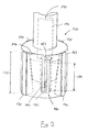
- Fig. 1 schematically shown is the front view of a honing machine 100, which can be used for machining of inner surfaces of holes in workpieces to perform one or more honing operations on the workpiece.
- a clamping plate 104 On the machine bed 102 of the honing machine a clamping plate 104 is fixed, which carries a workpiece 106 clamped thereon, which in the example is an engine block of a four-cylinder internal combustion engine.
- a plurality of cylinder bores 108 to 111 are formed with generally vertical orientation of their cylinder axes.
- the cylinder surfaces formed by the inner surfaces 115 of the cylinder bores are subjected to a quality-determining finishing on the honing machine, in which both the macro-shape of the cylinder surfaces, as well as their surface topography or surface structure are produced by suitable honing processes.
- each honing unit comprises a spindle box 122 fixed to the support structure and guiding the honing spindle 130.
- the honing spindle can be rotated about its longitudinal axis by means of a spindle motor attached to the spindle box.
- the lower end of the honing spindle is replaced by a Jointed rod formed at the lower, free end serving as a machining tool honing tool 140 is limited mechanically coupled mechanically movable.
- a mounted on the headstock lifting actuator causes the vertical movement of the honing spindle during insertion of the tool into the workpiece or when pulling out of the workpiece and is controlled during the honing process so that the honing tool within the bore of the workpiece performs a vertical reciprocating motion, the the rotational movement of the spindle generated by the spindle motor is superimposed about its longitudinal axis. Since the structure of such honing units is basically known, it will not be explained in detail here.
- a measuring system 150 integrated in the honing machine is integrated as an integral part of the honing machine.
- the single-spindle measuring system 150 has a measuring spindle box 152 attached to the support structure of the honing machine, which carries a vertically oriented measuring spindle 155.
- a spindle drive 158 is mounted on the spindle box and is designed to move the measuring spindle vertically up and down parallel to its longitudinal axis. Furthermore, the measuring spindle drive is able to turn the measuring spindle step by step by predeterminable angular amounts about its longitudinal axis.
- the lower end of the measuring spindle is formed by a joint rod, at the lower, free end of which a measurement head 160 of the measuring system constructed in the manner of a honing tool is limitedly movably and detachably mechanically coupled.
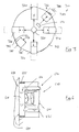
- the in Fig. 2 Measuring head shown in detail has a substantially bore-filling, cylindrical measuring head body 162, which carries on its circumference four uniformly distributed around the circumference supporting members 170 in the form of axially elongated support strips.
- the support members are movably guided within the measuring head body in the radial direction, biased by return springs, not shown in a radially inwardly directed feed direction and can by means of a Zustellsystems 190 are delivered in the radial direction to adjust the support diameter of the measuring head.
- the delivery system comprises an axially movable in the measuring spindle feed rod 192, at the lower end of a Zustellkonus 194 is mounted, the outwardly directed conical surface cooperate with corresponding, inwardly directed inclined surfaces of the support members in the manner of a wedge drive.
- the outwardly directed support surfaces of the support strips 170 extend substantially over the entire axial length of the measuring head and thus define the axial extent of a support region 172.
- the support region may extend over more than half or more than 60% or 70% or 80% of the axial length of the bore and, in particular, may also cover the central region of the bore between the inlet and the lower end.
- the measuring probe 180 carried by the measuring head body 162 is designed for measuring the surface roughness of the inner surface in the stylus method.
- the measuring sensor 185 of the measuring probe has a stylus tip 182 formed by a diamond needle, which can be moved in a straight line parallel to the central axis of the measuring head by means of an electric sensor drive 187 integrated in the measuring probe within a measuring range 189 along a rectilinear measuring path.
- the up and down movement of the stylus tip resulting from the sliding of the stylus tip on the rough inner surface is converted by means of an electromechanical transducer into electrical signals, which are supplied via not shown electrical leads to an evaluation system, also not shown.
- the position of the measuring probe along the measuring path is detected by a displacement transducer and corresponding path signals are also passed to the evaluation device, which determines from the signals a roughness profile from which suitable roughness parameters of the inner surface are determined in a known manner.
- the contamination-sensitive parts of the measuring sensor are oil-tightly encapsulated within the housing of the measuring sensor.
- an oil seal can be provided between the probe tip and the housing, through which a movable holder for the probe tip is movably guided.
- the probe tip can be protected against mechanical damage by suitable measures when entering the bore (and when retracting), for example by pulling in the probe tip or by moving out of the probe tip enclosing protective element.
- the linear measuring region 189 of the measuring probe lies completely within the support region 172 defined by the support strips 170 arranged adjacently in the circumferential direction.
- the outer, formed by a hard elastomeric material supporting surfaces of Abstützorgane have both axially above, and axially below the measuring range 189 support points.
- the measuring probe with the non-inventive tactile measuring sensor 185 lies completely in the circumferential direction between supporting organs. In this way, a vibration-insensitive fixation of the probe or the measuring sensor is secured within the workpiece bore, which ensures an unwanted relative movement between the probe and workpiece or surface to be measured during the measurement even in vibration-prone measuring environments.
- the measuring spindle is lowered by means of the measuring spindle drive 158 down to introduce the measuring head 160 into the cylinder bore 111 to be measured.
- the support strips 170 are retracted into their radially inner retraction position, so that the defined by the outer surfaces of the Abstützorgane effective diameter of the measuring head is a few millimeters smaller than the inner diameter of the cylinder bore.
- a gentle introduction of the measuring head is secured in the cylinder bore without the risk of damaging the inner surface to be measured.
- the probe tip of the probe is in its retracted position to avoid damage.
- the measuring spindle is then limitedly rotated with the aid of the measuring spindle drive 158 in order to move the probe tip into the region of the inner surface of the bore to be measured.
- the adjustment of the correct rotational position of the measuring spindle can also be carried out before or during the introduction of the measuring head into the cylinder bore.
- the drive-controlled fixing of the probe body or the measuring head 160 is initiated within the bore by the feed rod 192 is delivered in the direction of the measuring head by the drive unit 195 of the delivery system.
- the support strips 170 are slowly delivered radially outward in the direction of the inner surface, until they rest securely against the inner surface with a suitable biasing force.
- the delivery system is locked by a locking device, so that an unintentional dissolution of the fixation during the measurement is avoided.
- the measuring head 160 is securely fixed to the workpiece 106, the drive-side part of the measuring spindle from the measuring head side part of the measuring spindle can be partially decoupled, so that any vibration movements of the drive-side part can no longer be transferred to the fixed in the workpiece measuring head.
- the measuring system is housed in a separate measuring station of the honing machine, whereby a strong decoupling of machining vibrations is possible.
- the separate measuring machine can be arranged directly behind the honing machine in the workpiece flow.
- the measurement is performed.
- the probe tip 186 is moved radially outward into touching contact with the inner surface.
- the probe tip is moved with the aid of the sensor drive 187 over the desired measurement path and thereby recorded a roughness profile.
- the probe tip is automatically retracted to its retracted position in the probe body. Since displacement sensors for detecting the axial position of the measuring head and angle sensors for detecting the rotational position of the measuring spindle are provided on the measuring spindle, the position of the measuring section on the inner surface of the bore can be unambiguously assigned to a specific axial and circumferential region of the bore inner surface.
- a measuring path can extend over the entire maximum available measuring range 189 of the measuring probe. It is also possible to use only parts of this measuring range for the measurement. For example, a plurality of vertically spaced measuring sections can be measured in one and the same clamping position of the measuring head, for example, representative measurements for the inlet region of the bore, for a central region of the bore and for a region of the bore facing away from the inlet region. If measurements at other circumferential positions of the bore are desired, the fixation of the probe can be canceled by retracting the support strips and the measuring head can then be rotated by 30 °, 45 °, 90 ° or 180 ° by turning the measuring spindle in the bore around the probe in the circumferential direction to move to a new area to be measured. Thereafter, the measuring head in the manner already described is again fixed drive-controlled within the bore before the next measurement begins.
- a calibration device in the form of a measuring spindle 152 mounted reference ring 187 with a circular cylindrical inner surface whose diameter is substantially the diameter of the cylinder bore 111th equivalent.
- the reference ring may for example consist of a steel material, a ceramic or other corrosion-resistant and wear-resistant material.
- the reference ring 187 can also consist of such a material with a characteristic plateau structure.
- the reference ring has on its inner surface a defined surface structure, which correspond to certain roughness parameters determined.
- the roughness characteristics of the reference structure were determined in a reference measurement process using a classical roughness measurement system under essentially the same measurement conditions.
- the surface structure or the roughness is normally very similar to the surface structure desired on the machined cylinder inner surface with respect to all required roughness characteristics or identical with this.
- the measuring system may perform a test measurement before measuring a cylinder inner surface, in a measurement pause during the measurement and / or after completion of such a measurement at the reference device.
- the reference device can also be arranged next to the workpiece to be measured, so that the measuring spindle must be moved in the lateral direction for calibration between the workpiece to be measured and the reference device.
- the principle of the measuring system is suitable for holes of different diameters.
- the measuring system may include, for example, a plurality of differently dimensioned measuring heads, each of which covers a defined diameter range, for example of the order of magnitude of up to ten millimeters diameter variations.
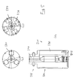
- Based Fig. 3 an embodiment of a measuring head 360 is explained, which allows a measurement of holes with very different diameters and covers, for example, a diameter range with up to 10% or 20% diameter variation.
- the measuring head body 362 similar to the in Fig. 2 shown embodiment, four arranged at 90 ° angularly arranged support members 370, which are guided radially displaceable in the tool body.
- the radial positions of the Abstützorgane and thus the The effective diameter of the support device is adjusted by means of a support device feed system 390, the structure of which with feed rod and Zustellkonus essentially the basis Fig. 2 explained structure can correspond.
- the measuring head carries two diametrically opposed measuring probes 380, 380 ', which are configured for a roughness measurement by means of a stylus method and accordingly each have a stylus tip 386, 386'.
- the probe sensor of the probe 380 is a skidless probe
- the probe 380 has a stylus with runners 387 which, for the moveable probe tip 386, descend a reference surface defined by the peaks of the roughness profile to allow for differential measurement
- a measuring head can thus contain measuring sensors operating according to different principles.
- a probe delivery system 395 separate from the support delivery system 390 is provided. This can include, for example, an electric motor drive arranged within the measuring head.
- the measuring head can also be designed in the manner of a honing tool with double expansion, so that for the radial adjustment of the probes another, for example, with a Zustellstange actuated delivery system can be provided.
- the structure of this measuring head essentially the structure of Fig. 2 shown embodiment correspond. Reference is therefore made to the description there.
- the Fig. 4 and 5 show other embodiments of measuring heads for measuring systems according to the invention.
- the measuring head 460 in Fig. 4 (a) is designed in the manner of a simply expandable honing tool and has a substantially circular cylindrical measuring head body 462, at whose upper end a bayonet coupling structure 465 is provided for coupling the measuring tool to a designed like a honing spindle measuring spindle of the measuring system.
- a bayonet coupling structure 465 is provided for coupling the measuring tool to a designed like a honing spindle measuring spindle of the measuring system.
- the measuring head has three circumferentially offset by 120 ° to the central axis of the measuring head probes 480, each having a movable parallel to the axial direction measuring sensor with a stylus tip 482 to simultaneously scan the inner surface of a bore at three 120 ° circumferentially offset measuring ranges.
- the support device has three support strips 470 which are circumferentially offset by 120 ° in each case and which can be delivered in the radial direction or retracted inward by a common infeed system 490.
- the feed system 490 has an axially displaceable within the measuring body double cone 494 with two axially offset conical surfaces, which cooperate with corresponding, inwardly directed inclined surfaces of support strips of Abst Reifenorgane 470 to ensure a parallel displacement of Abst Reifenorgane perpendicular to Meßkopfachse.
- the delivery system is resiliently biased in a support configuration with outwardly pushed out Abst Reifenorganen.
- the support members which are prestressed radially inward with the aid of suitable return springs, are withdrawn in this construction by pressing the feed rod 492 extending in the interior of the measuring spindle in the direction of the measuring head 460.
- the measuring head Since no external force of a feed rod introduced outside the measuring head is necessary to maintain this fixing position, it can be decoupled from the measuring head side part during the measurement, so that no vibrations are introduced into the measuring head via the feed system.
- the measuring head is thus within the bore to be measured self-holding fixed, whereby the measurement accuracy is improved and the sensitivity to shocks is reduced.
- the measuring head 410 in Fig. 4 (c) also has three evenly distributed around the circumference, radially adjustable support strips 415.
- three fixedly mounted guide rails 418 are provided in the circumferential direction therebetween.
- a single measuring probe 420 is provided for a roughness measurement and has a vertically movable stylus tip for this purpose.
- the measuring head 430 in Fig. 4 (d) has a support device with four each offset by 90 ° angle, radially movable Abstützorgn 435 and a total of eight fixedly attached to the measuring head body guide rails 436, which may for example consist of plastic and facilitate the careful insertion of the measuring head into the bore to be measured.
- the delivery system does not act on the fixed and not radially displaceable Abst Reifenorgane 570, but on using the Meßsonden Zustellsystem 590 radially adjustable probes 580, with Help the Zustellsystems are perpendicular to the central axis of the measuring head movable and serve as Abstweilorgane.
- the measuring probes 580 are retracted inwards, so that the measuring head reaches its minimum diameter, which allows easy insertion of the measuring head into the hole or a corresponding removal.
- the measuring head with withdrawn probes is inserted into the bore, then the delivery system is relieved, so that by the relieving coil spring 595, the three probes 580 are brought radially outward in abutting contact with the inner surface to be measured and thereby fix the measuring head together with the support strips 570 in the bore.
- the measuring head is fixed so firmly in the bore without the application of external forces, so that the fixation of the measuring head in the bore solely by the construction of the measuring head itself (with coil spring) is possible. Only to remove the fixation is foreign energy introduced from outside necessary. Since the measuring head holds itself in the hole, the rod, with which the measuring unit 565 is attached to the spindle, can be loosened for better decoupling between the machine and the measuring sensor. Thereafter, the measurement begins by shifting the stylus tips within the probes.
- the embodiment in Fig. 5 (c) has a selfish niethoid symmetry with four circumference offset by 90 °, radially deliverable probes 550.
- eight plastic guide strips 536 are mounted on the circumference of the measuring head, which prevent a direct metallic contact between the measuring head and the surrounding bore inner wall with retracted probes.
- Fig. 6 shows a schematic section of a measuring probe with an optical measuring sensor 610, which is adapted to detect a two-dimensionally extended, two-dimensional measuring range on the inner surface 601 of a cylindrical bore.
- the fixedly attached to the probe body measuring sensor 610 includes a microscope objective 611, which is moved to the measurement at a small distance from the inner surface 601 of the bore.
- the optical measuring sensor comprises a CCD chip or the like for converting the image acquired by the microscope objective 611 into electrical signals which are supplied to the evaluation unit of the measuring system.
- the measuring range is illuminated by means of LED lights 620.
- LED lights 620 for example LED lights.
- it is also possible to use other light sources, for example semiconductor lasers. Come as measuring principles of optical measuring sensors In addition to the simple image capture and the fringe projection, interferometric measurement methods or confocal microscopy into consideration, in order to obtain a depth information on the topography of the surface to be
- a cleaning device 630 which is designed to rinse the gap between the inner surface 601 and the light entry side of the microscope objective 611 by means of a liquid 631 which is transparent to the measuring radiation (eg visible light or ultraviolet light) and thereby to the surface of machining residues to free.
- a well-cleaned transparent honing oil is used in the example, which also serves according to the invention as an immersion liquid to improve the resolution and / or the depth of field of the optical measurement.
- the optical measuring sensor can be provided in addition to a tactile measuring sensor in order to detect other surface characteristics, for example the course of machining tracks, honing angles, groove widths, etc.
- FIG. 7 An embodiment of a measuring system designed for the measurement of cylindrically curved workpiece convex surfaces will now be explained.
- the measuring system may for example be integrated in a band finishing machine, with the cylindrical Werg Publishedabroughe a workpiece, such as main bearing surfaces and crank bearing surfaces of crankshafts are processed.
- a substantially cylindrical workpiece section 710 with a cylindrically curved workpiece outer surface 701 running around the central axis 711 of the workpiece section is shown in cross-section.
- the measuring system has a measuring head 760, which can be delivered by means of a hydraulic or electromechanical feed system in the radial direction of the workpiece section to move the measuring head for the measurement in a measuring position near the workpiece outer surface to be measured.
- the measuring head carries a permanently integrated measuring probe 780 with a stylus tip 782, which is displaceable linearly parallel to the axis 712 of the measuring head, of a non-inventive tactile measuring sensor.
- the axis 712 is the measuring head axis lying outside the measuring head 760, which is to be aligned coaxially with the corresponding workpiece axis 711 for measuring a cylindrical outer surface.
- the measuring head may also carry at least one optical measuring sensor, as used in connection with, for example, FIG Fig. 6 was explained. All of the types of measuring sensors explained in connection with the measurement of bore inner surfaces can also be used in the measurement of convexly curved workpiece outer surfaces.
- the measuring head is designed concave cylindrical on its side facing the workpiece.
- supportable support members 770 which can be designed in particular as axially elongate support strips aligned parallel to the axis 712, as explained in connection with the measuring heads for the bore inner surface measurement. By radial displacement of the support members 770 can be the measuring head 760 infinitely adjust to workpiece sections of different diameters.
- the support members 770 are moved with retracted measuring head 760 into a radial position, which secures a large-area contact of the supporting members on the workpiece surface when the measuring head is supported on the workpiece. Then, measuring head is moved by means of an electromechanical, pneumatic or hydraulic drive in the direction of the workpiece until the support members 770 put on the workpiece outer surface, wherein via a force control, the contact pressure is set to a suitable value. After the measuring head is fixed in this way on the workpiece, the measuring sensor is moved to its measuring position, in which the probe tip 782 is seated on the workpiece outer surface. Thereafter, the roughness measurement is carried out in the manner already described.
- the probe is movably mounted relative to the probe body and moved by means of a probe drive in the direction of the surface to be measured to set a suitable distance between the probe and surface, wherein the setting of the correct radial position before, during or after the fixation of the measuring head can be made on the workpiece.
- a measuring head for measuring convexly curved workpiece outer surfaces Abst Reifenorgane are firmly attached to the measuring head body, so not deliverable separately.
- the entire measuring head is delivered with the integrated, rigid Abstweilorganen on a shaft or other workpiece to be measured.
- the positioning of the measuring head relative to the workpiece and the fixation on the workpiece via a single controllable movement axis, namely the axis of movement of the measuring head, are controlled.
- the cooling lubricant used in the honing machine for processing is used as the immersion liquid. This can be cleaned before initiation between the optical measuring sensor and the workpiece surface.
- a liquid suitable as immersion liquid is supplied from a separate tank, which is preferably compatible with the cooling lubricant.
- This fluid may be new, original (still unused) coolant or even just a base oil with no or with a few additives.
- a small amount of the new liquid can be fed into the measuring chamber, ie into the gap between the measuring sensor and the workpiece surface. After the measurement, the liquid can flow into the machine bed and thus into the large coolant system in which the cooling lubricant used for processing rotates.
- the upper fluid channel 635 in Fig. 6 be connected via a metering valve to the immersion liquid tank separate from the cooling lubricant circuit, while the lower fluid channel opens into the cooling lubricant circuit.
- the optical quality of the immersion liquid can be secured without special measures regarding the filtering of the cooling lubricant.
- the supplied additional cooling lubricant can also be used to completely or partially compensate for the normal discharge of cooling lubricant with the wetted parts after processing.
- measuring sensors can be different Be combined measuring principles.
- at least one non-inventive tactile sensor at least one non-contact measuring sensor according to the invention may be present, for example an optical sensor for detecting the surface structure in order, for example, to allow conclusions about honing angles, groove widths, material-specific sizes or the like on the basis of suitable sectional images.
- an optical, wear-free measuring sensor can often be used fully to measure the roughness. Therefore, it may be possible to dispense with a tactile measuring sensor, even if roughness parameters are to be determined.
- FIGS. 1 to 5 and 7 Numerous embodiments of measuring systems and processing machines equipped with measuring systems are shown using the example of the use of a non-inventive tactile measuring sensor.
- the invention includes an optical sensor.
- connecting rod bores, bores in toothed wheels, compressor raceways and / or cylinder liners of larger diesel engines or other internal combustion engines can likewise be measured with the aid of measuring systems according to the invention.
- largely cylindrical bearing surfaces on crankshafts, camshafts or other shafts as well as other cylindrical workpieces, for example precision machined piston rods or the like can be measured by means of a measuring system designed for the measurement of convexly curved outer surfaces.
Landscapes
- Physics & Mathematics (AREA)
- Engineering & Computer Science (AREA)
- Mechanical Engineering (AREA)
- General Physics & Mathematics (AREA)
- Analytical Chemistry (AREA)
- Health & Medical Sciences (AREA)
- Life Sciences & Earth Sciences (AREA)
- Chemical & Material Sciences (AREA)
- Geometry (AREA)
- Biochemistry (AREA)
- General Health & Medical Sciences (AREA)
- Immunology (AREA)
- Pathology (AREA)
- Finish Polishing, Edge Sharpening, And Grinding By Specific Grinding Devices (AREA)
- A Measuring Device Byusing Mechanical Method (AREA)
- Length Measuring Devices With Unspecified Measuring Means (AREA)
Claims (16)
- Procédé de mesure de la surface d'une pièce à l'aide d'au moins une sonde de mesure qui présente un corps de sonde et au moins un capteur de mesure placé sur le corps de sonde, en particulier pour déterminer la structure superficielle de surfaces intérieures ou extérieures à courbure cylindrique,
dans lequel au moins un capteur optique de mesure est utilisé et un espace intermédiaire situé dans une zone de mesure entre le capteur de mesure et la surface de la pièce est rempli d'un liquide transparent pour le rayonnement de mesure,
caractérisé en ce que
la mesure est réalisée à proximité directe de la fabrication, directement après une dernière étape de traitement, sur la pièce terminée ou dans une étape intermédiaire du traitement,
en ce qu'un liquide de traitement est utilisé lors du traitement et
en ce que le liquide utilisé comme liquide de traitement lors du traitement de la surface de la pièce est utilisé comme dit liquide essentiellement transparent pour le rayonnement de mesure en utilisant le liquide de traitement comme liquide d'immersion pour le système optique. - Procédé de mesure selon la revendication 1, dans lequel le liquide est nettoyé avant l'exécution de la mesure.
- Procédé de mesure selon les revendications 1 ou 2, dans lequel la zone de mesure est nettoyée à l'aide d'un dispositif de nettoyage avant et/ou pendant la mesure, le nettoyage comportant de préférence un rinçage de la surface de la pièce à l'aide d'un liquide et/ou dans lequel la zone de mesure est d'abord nettoyée par soufflage de la surface de la pièce, le liquide étant ensuite amené entre le capteur optique de mesure et la surface de la pièce.
- Procédé de mesure selon l'une des revendications précédentes, dans lequel une zone de mesure bidimensionnelle de grande surface est saisie par le capteur optique de mesure, et/ou dans lequel la zone de mesure saisie par le capteur optique de mesure est éclairée pendant la mesure à l'aide d'au moins une source de lumière associée au capteur de mesure et/ou dans lequel une saisie d'image, une projection en ruban, une opération de mesure par interférométrie et/ou une opération de microscopie confocale sont exécutées à l'aide du capteur optique de mesure.
- Procédé de mesure selon l'une des revendications précédentes, caractérisé par un positionnement de la sonde de mesure par rapport à la pièce et une fixation du corps de sonde sur la pièce dans une position de mesure par soutien du corps de sonde sur la surface de la pièce à l'aide d'un dispositif de soutien qui présente au moins un organe de soutien, dans lequel, de préférence pour la mesure de la surface intérieure d'un alésage ménagé dans une pièce, le positionnement de la sonde de mesure, de préférence sous la commande d'un entraînement, comporte l'insertion de la sonde de mesure dans l'alésage, de préférence sous la commande d'un entraînement, et la fixation du corps de sonde, de préférence sous la commande d'un entraînement, sur la surface intérieure de l'alésage à l'aide d'un dispositif de soutien qui présente au moins un organe de soutien qui peut être ajusté en direction de la surface intérieure, et/ou dans lequel, pour la mesure de la surface intérieure d'un alésage, on utilise une tête de mesure qui comporte un jeu constitué de plusieurs organes de soutien répartis à la périphérie de la tête de mesure pour soutenir la tête de mesure sur la surface intérieure de l'alésage, au moins l'un des organes de soutien pouvant être ajusté en direction de la surface intérieure de l'alésage, le soutien s'effectuant de préférence à l'intérieur d'une zone de soutien qui s'étend dans la direction axiale de la partie de la pièce à mesurer et la mesure étant exécutée à l'intérieur d'une zone de mesure qui se superpose au moins en partie à la zone de soutien, la mesure étant de préférence réalisée à l'intérieur d'une zone de mesure située entièrement à l'intérieur de la zone de soutien.
- Procédé de mesure selon la revendication 5, dans lequel le capteur de mesure est déplacé par rapport au corps de sonde fixé pendant la mesure, la surface de la pièce étant palpée lors de la mesure de préférence le long d'un parcours linéaire de mesure.
- Procédé de mesure selon l'une des revendications précédentes, dans lequel la mesure de la surface de la pièce est réalisée immédiatement après une étape de traitement précédente de la surface de la pièce et/ou immédiatement avant une étape de traitement suivante sur la surface de la pièce, sur la pièce serrée dans un ensemble de serrage de traitement, le capteur de mesure étant de préférence déplacé avant ou après l'exécution d'une mesure dans la zone d'un dispositif de référence qui présente une structure de surface connue et définie, le capteur de mesure étant étalonné par mesure du dispositif de référence.
- Système de mesure de la surface d'une pièce, en particulier pour déterminer la structure superficielle de surfaces intérieures ou de surfaces extérieures à courbure cylindrique,
le système présentant au moins une sonde de mesure qui peut être amenée sur la pièce et qui présente un corps de sonde et au moins un capteur de mesure placé sur le corps de sonde,
au moins un capteur de mesure étant un capteur optique de mesure (610),
un dispositif de remplissage d'un espace intermédiaire situé entre le capteur de mesure et la surface de la pièce à mesurer par un liquide (631) transparent pour le rayonnement de mesure étant prévu dans la zone de mesure (650),
caractérisé en ce que
le système de mesure est configuré pour exécuter l'opération de mesure selon l'une des revendications précédentes et
en ce que le dispositif de remplissage de l'espace intermédiaire est conçu pour remplir l'espace intermédiaire par le liquide de traitement utilisé lors du traitement de la surface de la pièce en utilisant le liquide de traitement comme liquide d'immersion pour le système optique de mesure. - Système de mesure selon la revendication 8, dans lequel un dispositif de nettoyage qui nettoie le liquide de traitement utilisé lors du traitement de la surface de la pièce est associé au système de mesure, le liquide de traitement nettoyé étant utilisé comme liquide transparent servant à remplir l'espace intermédiaire.
- Système de mesure selon l'une des revendications 8 ou 9, caractérisé par un dispositif de nettoyage (630) qui nettoie la zone de mesure (650) avant et/ou pendant la mesure, le dispositif de nettoyage étant conçu de préférence pour souffler la surface de la pièce et/ou pour rincer la surface de la pièce par un liquide, le dispositif de nettoyage étant de préférence conçu pour souffler la surface de la pièce et pour ensuite rincer la surface de la pièce au moyen d'un liquide.
- Système de mesure selon l'une des revendications 8 à 10, dans lequel le capteur optique de mesure (610) présente un objectif (611) de microscope, et/ou dans lequel le capteur optique de mesure (610) comporte un convertisseur opto-électronique, en particulier un chip CCD, qui convertit l'image saisie par l'objectif (611) de microscope en signaux électriques et/ou dans lequel le capteur optique de mesure est conçu pour exécuter une simple saisie d'image, une projection en ruban, une opération de mesure par interférométrie et/ou une microscopie confocale, au moins une source de lumière (620) associée au capteur de mesure étant prévue pour éclairer la zone de mesure (650) pendant la mesure.
- Système de mesure selon l'une des revendications 8 à 11, caractérisé par un dispositif de soutien associé au capteur de mesure et présentant au moins un organe de soutien qui peut être ajusté sur la surface de la pièce à l'aide d'un entraînement d'ajustement, et qui fixe le corps de sonde sur la pièce dans une position de mesure en soutenant le corps de sonde sur la surface de la pièce, la sonde de mesure étant de préférence intégrée dans une tête de mesure qui présente un jeu de plusieurs organes de soutien, au moins l'un des organes de soutien étant monté de manière à pouvoir être déplacé par rapport au corps de la tête de mesure et pouvant être actionné par un système d'ajustement, le dispositif de soutien définissant de préférence une zone de soutien qui s'étend dans la direction axiale de la partie de la pièce de mesure à mesurer, le capteur de mesure étant actif à l'intérieur d'une zone de mesure qui se superpose au moins en partie à la zone de soutien, la zone de mesure étant de préférence située complètement à l'intérieur de la zone de soutien et/ou dans lequel au moins un capteur de mesure est disposé dans la direction périphérique et/ou dans la direction axiale entre deux organes de soutien voisins et/ou entre deux emplacements de soutien définis par des organes de soutien.
- Système de mesure selon l'une des revendications 8 à 12, dans lequel la sonde de mesure est intégrée dans une tête de mesure et un système d'ajustement de capteur de mesure est prévu pour ajuster la position radiale du capteur de mesure par rapport à l'axe de la tête de mesure.
- Système de mesure selon l'une des revendications 8 à 13, dans lequel la sonde de mesure présente au moins un capteur de mesure apte à être déplacé par rapport au corps de sonde à l'aide d'un entraînement de capteur, au moins un capteur de mesure étant de préférence conçu pour palper, la surface de la pièce le long d'un parcours linéaire de mesure.
- Machine de traitement dans laquelle au moins un système de mesure selon l'une des revendications 8 à 14 est intégré.
- Machine de traitement selon la revendication 15, dans laquelle la machine de traitement est une machine de rodage et une broche de la machine de rodage est utilisée comme broche de mesure (155) du système de mesure et/ou dans laquelle un dispositif d'évaluation du système de mesure est raccordé à un dispositif de commande de la machine de traitement en vue de la transmission de signaux et forme avec ce dernier un dispositif de régulation qui commande le traitement sur la base de données de mesure obtenues du système de mesure, de préférence la durée de traitement et/ou la poussée de supports de matière coupante pouvant être commandée sur la base de valeurs de mesure du système de mesure.
Applications Claiming Priority (3)
| Application Number | Priority Date | Filing Date | Title |
|---|---|---|---|
| DE102006050838A DE102006050838A1 (de) | 2006-03-09 | 2006-03-09 | Messverfahren, Messsystem und Bearbeitungsmaschine mit Messsystem |
| DE102006011904.5A DE102006011904B4 (de) | 2006-03-09 | 2006-03-09 | Messverfahren, Messsystem und Bearbeitungsmaschine mit Messsystem |
| PCT/EP2007/000754 WO2007101513A2 (fr) | 2006-03-09 | 2007-01-30 | Procédé de mesure, système de mesure et machine d'usinage doté de ce système de mesure |
Publications (2)
| Publication Number | Publication Date |
|---|---|
| EP1994362A2 EP1994362A2 (fr) | 2008-11-26 |
| EP1994362B1 true EP1994362B1 (fr) | 2015-01-21 |
Family
ID=37891920
Family Applications (1)
| Application Number | Title | Priority Date | Filing Date |
|---|---|---|---|
| EP07703110.2A Not-in-force EP1994362B1 (fr) | 2006-03-09 | 2007-01-30 | Procédé de mesure, système de mesure et machine d'usinage doté de ce système de mesure |
Country Status (3)
| Country | Link |
|---|---|
| EP (1) | EP1994362B1 (fr) |
| DE (1) | DE102006011904B4 (fr) |
| WO (1) | WO2007101513A2 (fr) |
Cited By (2)
| Publication number | Priority date | Publication date | Assignee | Title |
|---|---|---|---|---|
| WO2019072334A1 (fr) | 2017-10-13 | 2019-04-18 | Schaeffler Technologies AG & Co. KG | Machine de finissage et utilisation d'une machine de finissage |
| CN114986256A (zh) * | 2022-07-18 | 2022-09-02 | 成都飞机工业(集团)有限责任公司 | 一种多功能精加工粗糙度在机测量装置及测量方法 |
Families Citing this family (9)
| Publication number | Priority date | Publication date | Assignee | Title |
|---|---|---|---|---|
| DE102011017535A1 (de) | 2011-04-26 | 2012-10-31 | Endress + Hauser Conducta Gesellschaft für Mess- und Regeltechnik mbH + Co. KG | Sondeneinrichtung zum Messen einer Messgröße eines in einem Prozessbehälter enthaltenen Prozessmediums |
| DE102012103911A1 (de) * | 2012-05-04 | 2013-11-07 | Carl Mahr Holding Gmbh | Messvorrichtung für dimensionelle Mess- und Kenngrößen mit separater Steuereinrichtung |
| DE102014201417B4 (de) | 2014-01-27 | 2016-01-14 | Carl Zeiss Industrielle Messtechnik Gmbh | Vorrichtung und Verfahren zur Erfassung einer Rauheit und/oder eines Profils einer Oberfläche eines Messobjekts |
| DE102014201438B4 (de) | 2014-01-27 | 2023-01-26 | Carl Zeiss Industrielle Messtechnik Gmbh | Vorrichtung und Verfahren zur Halterung einer Erfassungseinrichtung zur Erfassung von Eigenschaften eines Messobjekts |
| DE102016112439A1 (de) * | 2016-03-23 | 2017-09-28 | Gottfried Wilhelm Leibniz Universität Hannover | Optisches Messsystem, insbesondere für eine Fertigungsmaschine |
| CN106863011A (zh) * | 2017-02-27 | 2017-06-20 | 哈尔滨汽轮机厂有限责任公司 | 一种汽轮机高压缸开档内孔精加工辅助装置及精加工方法 |
| DE102017124726B4 (de) * | 2017-07-05 | 2019-01-17 | Albis Plastic Gmbh | Inspektionsvorrichtung |
| CN108709673B (zh) * | 2018-07-27 | 2023-09-26 | 北方民族大学 | 珩削力测试装置及测试方法 |
| CN109489590B (zh) * | 2018-11-30 | 2020-10-20 | 中北大学 | 珩磨孔的检测装置 |
Citations (2)
| Publication number | Priority date | Publication date | Assignee | Title |
|---|---|---|---|---|
| DE3241710A1 (de) * | 1982-11-11 | 1984-05-17 | Diffracto Ltd., Windsor, Ontario | Verfahren und vorrichtung zur pruefung von teilen oder werkstuecken |
| EP0697591A1 (fr) * | 1994-08-09 | 1996-02-21 | CENTRE DE RECHERCHES METALLURGIQUES CENTRUM VOOR RESEARCH IN DE METALLURGIE Association sans but lucratif | Dispositif pour l'inspection de la surface d'un cylindre de laminoir |
Family Cites Families (14)
| Publication number | Priority date | Publication date | Assignee | Title |
|---|---|---|---|---|
| DE2810322C2 (de) * | 1978-03-10 | 1982-11-25 | Peter 7442 Neuffen Nagel | Honmaschine |
| DE3024331C2 (de) * | 1980-06-27 | 1982-10-21 | Ludwig Dr.-Ing. 7500 Karlsruhe Pietzsch | Meßvorrichtung für den Zylinderverzug in Zylinderräumen |
| DE3037519C2 (de) * | 1980-10-03 | 1982-11-11 | Ludwig Dr.-Ing. 7500 Karlsruhe Pietzsch | Meßvorrichtung zum Vermessen von Bohrungen |
| DE8017217U1 (de) * | 1980-06-27 | 1985-01-03 | Pietzsch, Ludwig, Dr.-Ing., 7500 Karlsruhe | Meßvorrichtung zum Vermessen der Innenkontur von Bohrungen |
| IT1178526B (it) * | 1984-10-01 | 1987-09-09 | Speroni Spa | Procedimento per l'esecuzione di collaudi veloci in processo e relativa apparecchiatura |
| DE3719422A1 (de) * | 1986-12-19 | 1988-06-30 | Hommelwerke Gmbh | Vorrichtung zur beruehrungsfreien messung eines abstandes von einer oberflaeche, insbesondere zur abtastung einer kontur einer oberflaeche eines werkstueckes laengs eines messweges |
| DE3900106C2 (de) * | 1989-01-04 | 1994-01-05 | Bbc Pat Mestechnik Gmbh | Verfahren und Vorrichtung zum Vermessen der Form von Zylinderbohrungen in Werkstücken |
| US5419188A (en) * | 1991-05-20 | 1995-05-30 | Otis Engineering Corporation | Reeled tubing support for downhole equipment module |
| US5895927A (en) * | 1995-06-30 | 1999-04-20 | The United States Of America As Represented By The Secretary Of The Air Force | Electro-optic, noncontact, interior cross-sectional profiler |
| GB9719514D0 (en) * | 1997-09-12 | 1997-11-19 | Thames Water Utilities | Non-contact measuring apparatus |
| DE20023557U1 (de) * | 2000-10-21 | 2004-12-09 | Hommel Incotec Gmbh | Vorrichtung zum Vermessen von Bohrungen eines Werkstücks |
| DE10060967B4 (de) * | 2000-12-06 | 2006-05-11 | Nagel Maschinen- Und Werkzeugfabrik Gmbh | Verfahren und Honvorrichtung zur Honbearbeitung sowie Referenzeinrichtung |
| DE10220562B4 (de) * | 2002-05-03 | 2005-11-10 | Nagel Maschinen- Und Werkzeugfabrik Gmbh | Verfahren zur Ausrichtung eines in einer Honspindel einspannbaren Honwerkzeugs und einer Bohrung eines Werkstücks zueinander sowie Honmaschine |
| JP2005083800A (ja) * | 2003-09-05 | 2005-03-31 | Hitachi Ltd | 欠陥検査方法及び欠陥検査装置 |
-
2006
- 2006-03-09 DE DE102006011904.5A patent/DE102006011904B4/de not_active Expired - Fee Related
-
2007
- 2007-01-30 WO PCT/EP2007/000754 patent/WO2007101513A2/fr active Application Filing
- 2007-01-30 EP EP07703110.2A patent/EP1994362B1/fr not_active Not-in-force
Patent Citations (2)
| Publication number | Priority date | Publication date | Assignee | Title |
|---|---|---|---|---|
| DE3241710A1 (de) * | 1982-11-11 | 1984-05-17 | Diffracto Ltd., Windsor, Ontario | Verfahren und vorrichtung zur pruefung von teilen oder werkstuecken |
| EP0697591A1 (fr) * | 1994-08-09 | 1996-02-21 | CENTRE DE RECHERCHES METALLURGIQUES CENTRUM VOOR RESEARCH IN DE METALLURGIE Association sans but lucratif | Dispositif pour l'inspection de la surface d'un cylindre de laminoir |
Cited By (4)
| Publication number | Priority date | Publication date | Assignee | Title |
|---|---|---|---|---|
| WO2019072334A1 (fr) | 2017-10-13 | 2019-04-18 | Schaeffler Technologies AG & Co. KG | Machine de finissage et utilisation d'une machine de finissage |
| DE102017123824B4 (de) | 2017-10-13 | 2020-06-04 | Schaeffler Technologies AG & Co. KG | Honmaschine und Verwendung einer Honmaschine |
| CN114986256A (zh) * | 2022-07-18 | 2022-09-02 | 成都飞机工业(集团)有限责任公司 | 一种多功能精加工粗糙度在机测量装置及测量方法 |
| CN114986256B (zh) * | 2022-07-18 | 2022-12-13 | 成都飞机工业(集团)有限责任公司 | 一种多功能精加工粗糙度在机测量装置及测量方法 |
Also Published As
| Publication number | Publication date |
|---|---|
| WO2007101513A3 (fr) | 2008-06-05 |
| WO2007101513A2 (fr) | 2007-09-13 |
| DE102006011904B4 (de) | 2017-09-21 |
| DE102006011904A1 (de) | 2007-09-13 |
| EP1994362A2 (fr) | 2008-11-26 |
Similar Documents
| Publication | Publication Date | Title |
|---|---|---|
| EP1994362B1 (fr) | Procédé de mesure, système de mesure et machine d'usinage doté de ce système de mesure | |
| DE102006050838A1 (de) | Messverfahren, Messsystem und Bearbeitungsmaschine mit Messsystem | |
| DE102010011470B9 (de) | Verfahren und Vorrichtung zur messungsunterstützten Feinbearbeitung von Werkstückoberflächen sowie Messsystem | |
| DE19616663B4 (de) | Meßgerät | |
| DE102008061444B4 (de) | Drehmaschine mit einer Messvorrichtung und Verfahren zum Vermessen eines Werkstückes auf solch einer Drehmaschine | |
| DE19840801B4 (de) | Werkzeugmaschine mit automatischer Prozesssteuerung/Überwachung und Verfahren zum Bearbeiten | |
| EP2190626B1 (fr) | Procédé et dispositif d'usinage de pièces | |
| DE102012110673B4 (de) | Werkzeugmaschine und Verfahren zur Vermessung eines Werkstücks | |
| EP0779849B1 (fr) | Procede et dispositif permettant de detecter et de corriger des defauts de jointure et des defauts dus a l'usure de l'outil lors d'operations de percage de precision | |
| DE102007001620B4 (de) | Verfahren zum Betrieb einer Bearbeitungsmaschine sowie Werkzeughalterung | |
| DE102008045470A1 (de) | Verfahren zur Bestimmung des Verschleißzustandes | |
| DE102008000489B3 (de) | Verfahren und Vorrichtung zur Reparatur eines Schleifringes im eingebauten Zustand | |
| DE202014011033U1 (de) | Messvorrichtung | |
| DE69912162T2 (de) | Schleifmaschine | |
| EP1887311A2 (fr) | Procédé destiné à mesurer la microstructure de surfaces de trous cylindriques et dispositif de mesure destiné à la réalisation du procédé de mesure | |
| DE102007035064A1 (de) | Verfahren zum Messen der Mikrostruktur von Oberflächen von Zylinderbohrungen und Messvorrichtung zur Durchführung des Messverfahrens | |
| EP0346288B1 (fr) | Méthode et appareil pour vérifier sans contact les dimensions d'un outil | |
| DE3704791A1 (de) | Verfahren und vorrichtung zur vermessung von koerpern | |
| DE3942805C2 (fr) | ||
| DE102008004849B4 (de) | Vorrichtung und Verfahren zum Bearbeiten von Werkstücken | |
| DE3610160A1 (de) | Vorrichtung zum optischen pruefen der oberflaeche von werkstuecken | |
| EP2523776B1 (fr) | Dispositif et procédé de détermination de la position d'une surface de travail d'un disque de travail | |
| DE10205212A1 (de) | Meßeinrichtung für Maschinen zum Bearbeiten von Werkstücken, insbesondere von Kurbelwellen, Nockenwellen | |
| DE102016006659B4 (de) | Messsystem und Verfahren zur berührungslosen Vermessung von Werkstücken | |
| DE19641719C1 (de) | Bohrungsmeßkopf |
Legal Events
| Date | Code | Title | Description |
|---|---|---|---|
| PUAI | Public reference made under article 153(3) epc to a published international application that has entered the european phase |
Free format text: ORIGINAL CODE: 0009012 |
|
| 17P | Request for examination filed |
Effective date: 20081006 |
|
| AK | Designated contracting states |
Kind code of ref document: A2 Designated state(s): AT BE BG CH CY CZ DE DK EE ES FI FR GB GR HU IE IS IT LI LT LU LV MC NL PL PT RO SE SI SK TR |
|
| AX | Request for extension of the european patent |
Extension state: AL BA HR MK RS |
|
| DAX | Request for extension of the european patent (deleted) | ||
| 17Q | First examination report despatched |
Effective date: 20121221 |
|
| APBK | Appeal reference recorded |
Free format text: ORIGINAL CODE: EPIDOSNREFNE |
|
| APBN | Date of receipt of notice of appeal recorded |
Free format text: ORIGINAL CODE: EPIDOSNNOA2E |
|
| APBR | Date of receipt of statement of grounds of appeal recorded |
Free format text: ORIGINAL CODE: EPIDOSNNOA3E |
|
| APAF | Appeal reference modified |
Free format text: ORIGINAL CODE: EPIDOSCREFNE |
|
| APBT | Appeal procedure closed |
Free format text: ORIGINAL CODE: EPIDOSNNOA9E |
|
| GRAP | Despatch of communication of intention to grant a patent |
Free format text: ORIGINAL CODE: EPIDOSNIGR1 |
|
| INTG | Intention to grant announced |
Effective date: 20140731 |
|
| GRAS | Grant fee paid |
Free format text: ORIGINAL CODE: EPIDOSNIGR3 |
|
| GRAA | (expected) grant |
Free format text: ORIGINAL CODE: 0009210 |
|
| AK | Designated contracting states |
Kind code of ref document: B1 Designated state(s): AT BE BG CH CY CZ DE DK EE ES FI FR GB GR HU IE IS IT LI LT LU LV MC NL PL PT RO SE SI SK TR |
|
| REG | Reference to a national code |
Ref country code: GB Ref legal event code: FG4D Free format text: NOT ENGLISH |
|
| REG | Reference to a national code |
Ref country code: CH Ref legal event code: EP |
|
| REG | Reference to a national code |
Ref country code: IE Ref legal event code: FG4D Free format text: LANGUAGE OF EP DOCUMENT: GERMAN |
|
| REG | Reference to a national code |
Ref country code: AT Ref legal event code: REF Ref document number: 707739 Country of ref document: AT Kind code of ref document: T Effective date: 20150215 |
|
| REG | Reference to a national code |
Ref country code: DE Ref legal event code: R096 Ref document number: 502007013694 Country of ref document: DE Effective date: 20150305 |
|
| REG | Reference to a national code |
Ref country code: NL Ref legal event code: VDEP Effective date: 20150121 |
|
| REG | Reference to a national code |
Ref country code: LT Ref legal event code: MG4D |
|
| PG25 | Lapsed in a contracting state [announced via postgrant information from national office to epo] |
Ref country code: BE Free format text: LAPSE BECAUSE OF NON-PAYMENT OF DUE FEES Effective date: 20150131 |
|
| PG25 | Lapsed in a contracting state [announced via postgrant information from national office to epo] |
Ref country code: SE Free format text: LAPSE BECAUSE OF FAILURE TO SUBMIT A TRANSLATION OF THE DESCRIPTION OR TO PAY THE FEE WITHIN THE PRESCRIBED TIME-LIMIT Effective date: 20150121 Ref country code: BG Free format text: LAPSE BECAUSE OF FAILURE TO SUBMIT A TRANSLATION OF THE DESCRIPTION OR TO PAY THE FEE WITHIN THE PRESCRIBED TIME-LIMIT Effective date: 20150421 Ref country code: LT Free format text: LAPSE BECAUSE OF FAILURE TO SUBMIT A TRANSLATION OF THE DESCRIPTION OR TO PAY THE FEE WITHIN THE PRESCRIBED TIME-LIMIT Effective date: 20150121 Ref country code: ES Free format text: LAPSE BECAUSE OF FAILURE TO SUBMIT A TRANSLATION OF THE DESCRIPTION OR TO PAY THE FEE WITHIN THE PRESCRIBED TIME-LIMIT Effective date: 20150121 Ref country code: FI Free format text: LAPSE BECAUSE OF FAILURE TO SUBMIT A TRANSLATION OF THE DESCRIPTION OR TO PAY THE FEE WITHIN THE PRESCRIBED TIME-LIMIT Effective date: 20150121 |
|
| REG | Reference to a national code |
Ref country code: CH Ref legal event code: PL |
|
| PG25 | Lapsed in a contracting state [announced via postgrant information from national office to epo] |
Ref country code: PL Free format text: LAPSE BECAUSE OF FAILURE TO SUBMIT A TRANSLATION OF THE DESCRIPTION OR TO PAY THE FEE WITHIN THE PRESCRIBED TIME-LIMIT Effective date: 20150121 Ref country code: GR Free format text: LAPSE BECAUSE OF FAILURE TO SUBMIT A TRANSLATION OF THE DESCRIPTION OR TO PAY THE FEE WITHIN THE PRESCRIBED TIME-LIMIT Effective date: 20150422 Ref country code: LV Free format text: LAPSE BECAUSE OF FAILURE TO SUBMIT A TRANSLATION OF THE DESCRIPTION OR TO PAY THE FEE WITHIN THE PRESCRIBED TIME-LIMIT Effective date: 20150121 Ref country code: IS Free format text: LAPSE BECAUSE OF FAILURE TO SUBMIT A TRANSLATION OF THE DESCRIPTION OR TO PAY THE FEE WITHIN THE PRESCRIBED TIME-LIMIT Effective date: 20150521 Ref country code: NL Free format text: LAPSE BECAUSE OF FAILURE TO SUBMIT A TRANSLATION OF THE DESCRIPTION OR TO PAY THE FEE WITHIN THE PRESCRIBED TIME-LIMIT Effective date: 20150121 |
|
| REG | Reference to a national code |
Ref country code: DE Ref legal event code: R097 Ref document number: 502007013694 Country of ref document: DE |
|
| PG25 | Lapsed in a contracting state [announced via postgrant information from national office to epo] |
Ref country code: MC Free format text: LAPSE BECAUSE OF FAILURE TO SUBMIT A TRANSLATION OF THE DESCRIPTION OR TO PAY THE FEE WITHIN THE PRESCRIBED TIME-LIMIT Effective date: 20150121 Ref country code: SK Free format text: LAPSE BECAUSE OF FAILURE TO SUBMIT A TRANSLATION OF THE DESCRIPTION OR TO PAY THE FEE WITHIN THE PRESCRIBED TIME-LIMIT Effective date: 20150121 Ref country code: CH Free format text: LAPSE BECAUSE OF NON-PAYMENT OF DUE FEES Effective date: 20150131 Ref country code: LI Free format text: LAPSE BECAUSE OF NON-PAYMENT OF DUE FEES Effective date: 20150131 Ref country code: EE Free format text: LAPSE BECAUSE OF FAILURE TO SUBMIT A TRANSLATION OF THE DESCRIPTION OR TO PAY THE FEE WITHIN THE PRESCRIBED TIME-LIMIT Effective date: 20150121 Ref country code: DK Free format text: LAPSE BECAUSE OF FAILURE TO SUBMIT A TRANSLATION OF THE DESCRIPTION OR TO PAY THE FEE WITHIN THE PRESCRIBED TIME-LIMIT Effective date: 20150121 Ref country code: RO Free format text: LAPSE BECAUSE OF FAILURE TO SUBMIT A TRANSLATION OF THE DESCRIPTION OR TO PAY THE FEE WITHIN THE PRESCRIBED TIME-LIMIT Effective date: 20150121 Ref country code: CZ Free format text: LAPSE BECAUSE OF FAILURE TO SUBMIT A TRANSLATION OF THE DESCRIPTION OR TO PAY THE FEE WITHIN THE PRESCRIBED TIME-LIMIT Effective date: 20150121 |
|
| REG | Reference to a national code |
Ref country code: IE Ref legal event code: MM4A |
|
| PLBE | No opposition filed within time limit |
Free format text: ORIGINAL CODE: 0009261 |
|
| STAA | Information on the status of an ep patent application or granted ep patent |
Free format text: STATUS: NO OPPOSITION FILED WITHIN TIME LIMIT |
|
| REG | Reference to a national code |
Ref country code: FR Ref legal event code: ST Effective date: 20151116 |
|
| GBPC | Gb: european patent ceased through non-payment of renewal fee |
Effective date: 20150421 |
|
| 26N | No opposition filed |
Effective date: 20151022 |
|
| PG25 | Lapsed in a contracting state [announced via postgrant information from national office to epo] |
Ref country code: IT Free format text: LAPSE BECAUSE OF FAILURE TO SUBMIT A TRANSLATION OF THE DESCRIPTION OR TO PAY THE FEE WITHIN THE PRESCRIBED TIME-LIMIT Effective date: 20150121 |
|
| PG25 | Lapsed in a contracting state [announced via postgrant information from national office to epo] |
Ref country code: IE Free format text: LAPSE BECAUSE OF NON-PAYMENT OF DUE FEES Effective date: 20150130 Ref country code: GB Free format text: LAPSE BECAUSE OF NON-PAYMENT OF DUE FEES Effective date: 20150421 |
|
| PG25 | Lapsed in a contracting state [announced via postgrant information from national office to epo] |
Ref country code: FR Free format text: LAPSE BECAUSE OF NON-PAYMENT OF DUE FEES Effective date: 20150323 Ref country code: SI Free format text: LAPSE BECAUSE OF FAILURE TO SUBMIT A TRANSLATION OF THE DESCRIPTION OR TO PAY THE FEE WITHIN THE PRESCRIBED TIME-LIMIT Effective date: 20150121 |
|
| REG | Reference to a national code |
Ref country code: AT Ref legal event code: MM01 Ref document number: 707739 Country of ref document: AT Kind code of ref document: T Effective date: 20150130 |
|
| PG25 | Lapsed in a contracting state [announced via postgrant information from national office to epo] |
Ref country code: AT Free format text: LAPSE BECAUSE OF NON-PAYMENT OF DUE FEES Effective date: 20150130 |
|
| PG25 | Lapsed in a contracting state [announced via postgrant information from national office to epo] |
Ref country code: HU Free format text: LAPSE BECAUSE OF FAILURE TO SUBMIT A TRANSLATION OF THE DESCRIPTION OR TO PAY THE FEE WITHIN THE PRESCRIBED TIME-LIMIT; INVALID AB INITIO Effective date: 20070130 |
|
| PG25 | Lapsed in a contracting state [announced via postgrant information from national office to epo] |
Ref country code: CY Free format text: LAPSE BECAUSE OF FAILURE TO SUBMIT A TRANSLATION OF THE DESCRIPTION OR TO PAY THE FEE WITHIN THE PRESCRIBED TIME-LIMIT Effective date: 20150121 |
|
| PG25 | Lapsed in a contracting state [announced via postgrant information from national office to epo] |
Ref country code: PT Free format text: LAPSE BECAUSE OF FAILURE TO SUBMIT A TRANSLATION OF THE DESCRIPTION OR TO PAY THE FEE WITHIN THE PRESCRIBED TIME-LIMIT Effective date: 20150521 |
|
| PG25 | Lapsed in a contracting state [announced via postgrant information from national office to epo] |
Ref country code: TR Free format text: LAPSE BECAUSE OF FAILURE TO SUBMIT A TRANSLATION OF THE DESCRIPTION OR TO PAY THE FEE WITHIN THE PRESCRIBED TIME-LIMIT Effective date: 20150121 |
|
| PG25 | Lapsed in a contracting state [announced via postgrant information from national office to epo] |
Ref country code: LU Free format text: LAPSE BECAUSE OF NON-PAYMENT OF DUE FEES Effective date: 20150130 |
|
| PGFP | Annual fee paid to national office [announced via postgrant information from national office to epo] |
Ref country code: DE Payment date: 20180125 Year of fee payment: 12 |
|
| REG | Reference to a national code |
Ref country code: DE Ref legal event code: R119 Ref document number: 502007013694 Country of ref document: DE |
|
| PG25 | Lapsed in a contracting state [announced via postgrant information from national office to epo] |
Ref country code: DE Free format text: LAPSE BECAUSE OF NON-PAYMENT OF DUE FEES Effective date: 20190801 |