EP1993323A1 - Ohrstück für eine Hörvorrichtung mit Bajonettverschluss - Google Patents
Ohrstück für eine Hörvorrichtung mit Bajonettverschluss Download PDFInfo
- Publication number
- EP1993323A1 EP1993323A1 EP08103972A EP08103972A EP1993323A1 EP 1993323 A1 EP1993323 A1 EP 1993323A1 EP 08103972 A EP08103972 A EP 08103972A EP 08103972 A EP08103972 A EP 08103972A EP 1993323 A1 EP1993323 A1 EP 1993323A1
- Authority
- EP
- European Patent Office
- Prior art keywords
- ear
- earpiece
- bayonet
- receiver
- handset
- Prior art date
- Legal status (The legal status is an assumption and is not a legal conclusion. Google has not performed a legal analysis and makes no representation as to the accuracy of the status listed.)
- Granted
Links
Images

Classifications
-
- H—ELECTRICITY
- H04—ELECTRIC COMMUNICATION TECHNIQUE
- H04R—LOUDSPEAKERS, MICROPHONES, GRAMOPHONE PICK-UPS OR LIKE ACOUSTIC ELECTROMECHANICAL TRANSDUCERS; DEAF-AID SETS; PUBLIC ADDRESS SYSTEMS
- H04R25/00—Deaf-aid sets, i.e. electro-acoustic or electro-mechanical hearing aids; Electric tinnitus maskers providing an auditory perception
- H04R25/60—Mounting or interconnection of hearing aid parts, e.g. inside tips, housings or to ossicles
-
- H—ELECTRICITY
- H04—ELECTRIC COMMUNICATION TECHNIQUE
- H04R—LOUDSPEAKERS, MICROPHONES, GRAMOPHONE PICK-UPS OR LIKE ACOUSTIC ELECTROMECHANICAL TRANSDUCERS; DEAF-AID SETS; PUBLIC ADDRESS SYSTEMS
- H04R2225/00—Details of deaf aids covered by H04R25/00, not provided for in any of its subgroups
- H04R2225/021—Behind the ear [BTE] hearing aids
- H04R2225/0213—Constructional details of earhooks, e.g. shape, material
-
- H—ELECTRICITY
- H04—ELECTRIC COMMUNICATION TECHNIQUE
- H04R—LOUDSPEAKERS, MICROPHONES, GRAMOPHONE PICK-UPS OR LIKE ACOUSTIC ELECTROMECHANICAL TRANSDUCERS; DEAF-AID SETS; PUBLIC ADDRESS SYSTEMS
- H04R2225/00—Details of deaf aids covered by H04R25/00, not provided for in any of its subgroups
- H04R2225/57—Aspects of electrical interconnection between hearing aid parts
-
- H—ELECTRICITY
- H04—ELECTRIC COMMUNICATION TECHNIQUE
- H04R—LOUDSPEAKERS, MICROPHONES, GRAMOPHONE PICK-UPS OR LIKE ACOUSTIC ELECTROMECHANICAL TRANSDUCERS; DEAF-AID SETS; PUBLIC ADDRESS SYSTEMS
- H04R25/00—Deaf-aid sets, i.e. electro-acoustic or electro-mechanical hearing aids; Electric tinnitus maskers providing an auditory perception
- H04R25/65—Housing parts, e.g. shells, tips or moulds, or their manufacture
- H04R25/652—Ear tips; Ear moulds
Definitions
- the present invention relates to an ear piece for a hearing device that can be worn in the ear canal, with a handset including a earpiece at the sound outlet and an ear cup in which the handset is fixed, which holds the earpiece in the ear canal and the inner ear when worn in the ear canal Side, which faces the eardrum, and has an opposite outer side, to which the earpiece is removably attached.
- a hearing device is understood here to mean in particular a device that can be worn on the ear, such as a hearing aid, a headset, a headset and the like.
- Hearing aids are portable hearing aids that are used to care for the hearing impaired.
- different types of hearing aids such as behind-the-ear hearing aids (BTE) and in-the-ear hearing aids (ITO), e.g. also Concha hearing aids or canal hearing aids (CIC), provided.
- BTE behind-the-ear hearing aids
- ITO in-the-ear hearing aids
- CIC canal hearing aids
- the hearing aids listed by way of example are worn on the outer ear or in the ear canal.
- bone conduction hearing aids, implantable or vibrotactile hearing aids are also available on the market. The stimulation of the damaged hearing takes place either mechanically or electrically.
- Hearing aids have in principle as essential components an input transducer, an amplifier and an output transducer.
- the input transducer is usually a sound receiver, z. As a microphone, and / or an electromagnetic receiver, for. B. an induction coil.
- the output transducer is usually used as an electroacoustic transducer, z. As miniature speaker, or as an electromechanical transducer, z. B. bone conduction, realized.
- the amplifier is usually integrated in a signal processing unit. This basic structure is in FIG. 1 shown using the example of a behind-the-ear hearing aid. In a hearing aid housing 1 for Carrying behind the ear, one or more microphones 2 are installed for recording the sound from the environment.
- a signal processing unit 3 which is also integrated in the hearing aid housing 1, processes the microphone signals and amplifies them.
- the output signal of the signal processing unit 3 is transmitted to a loudspeaker or earpiece 4, which outputs an acoustic signal.
- the sound is optionally transmitted via a sound tube, which is fixed with an earmold in the ear canal, to the eardrum of the device carrier.
- the power supply of the hearing device and in particular of the signal processing unit 3 is carried out by a likewise integrated into the hearing aid housing 1 battery. 5
- RIC devices receiver in canal
- a receiver unit to be inserted into the auditory canal.
- the earphones are plugged into the respective, standardized or individual ear shell.
- the receiver module consists of an earmold to which a handset is attached.
- the attachment is made with a specially shaped fastener that holds the hand on the one hand and on the other hand screwed to the earmold.
- the object of the present invention is thus to provide an ear piece for a hearing device and in particular a hearing aid, in which the handset is fastened on the one hand with high holding power and on the other hand easily replaceable in an ear cup.
- an ear piece for a hearing device that can be worn in the ear canal, with a handset including a earpiece at the sound outlet and an ear cup in which the handset is fixed, which holds the earpiece in the ear canal and when worn in the ear canal an inner side facing the tympanic membrane and having an opposite outer side to which the earpiece is removably attached, the earpiece being secured to the earcup with a bayonet fitting, and a first part of the bayonet fitting being fixedly connected to the earpiece and a second part of the bayonet lock is rotated from the inside of the ear cup to the first part of the bayonet lock.
- the bayonet lock ensures on the one hand a much higher holding force than, for example, a detachable Snap connection.
- a detachable Snap connection On the other hand, when closing the bayonet closure no closure components are bent or strongly rubbed against each other, which is why it hardly comes to wear.
- an adapter is mounted in the ear cup, in which the second part of the bayonet lock is rotatably mounted.
- the second part of the bayonet catch protrudes from the surface of the ear shell on its inner side, ie the side facing the eardrum when worn, and has at least two surfaces parallel to one another and to the axis of the bayonet closure. This makes it possible to use a simple tool, such as a small pair of pliers, to open the bayonet lock without destroying a wax guard located in the second part of the bayonet closure.
- the first part of the bayonet lock may have a cone-shaped portion which is cut off on two opposite sides of the parallel surfaces of the second part of the bayonet closure accordingly.
- the cone ensures a seat of the listener in the ear cup coaxial with the sound channel of the ear cup or the adapter and is at the same time a part of the bayonet with the cut sides.
- a seal may be arranged between the first and second part of the bayonet closure. With it, the closure is sealed against contamination and noise.
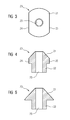
- FIG. 3 shows this earphone 20 from the sound output side.
- FIGS. 4 and 5 show this earpiece 20 each in cross section, the sections are rotated by 90 ° relative to each other.
- the earpiece 20 consists essentially of a conical portion 21 and a subsequent to the wide portion of the cone tubular portion 22.
- a sound channel 23 penetrates the conical portion 21 and the tubular portion 22nd
- the cone-shaped portion 21 is cut off on two opposite sides parallel to the cone axis, resulting in two parallel side surfaces 24 and 25. These are both in the top view of FIG. 3 as well as in the cross-sectional view of FIG. 4 but not in the 90 ° rotated view of FIG. 5 to recognize.
- the nozzle 20 is preferably made of a hard plastic.
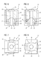
- the second part 31 of the bayonet lock is according to FIG. 6 a part of the earmold adapter 12. This second part 31 is rotatably mounted in a hard outer shell 32 of the adapter 12.
- the adapter cup 32 has an inner side 33 which, when the earpiece is carried in the ear canal, faces the eardrum. A piece of the second part 31 of the bayonet lock protrudes from this inner side 33. This is also in FIG. 7 to see which is a plan view of the adapter 12 from this inside.
- the second part 31 In the usual manner for bayonet fitting the second part 31 is after inserting the earpiece 20 by a certain angle, here 90 °, rotated. To easily rotate the second part 31, it has at least two flattened sides 37, 38 projecting from the inside 33. This allows the second part 31 of the bayonet lock, for example, with the help of a simple pliers or mounting aid easily grab and turn.
- the rotated state of the bayonet lock is in the FIGS. 8 and 9 shown.
- the recess 36 is engaged behind by the cone-shaped portion 21.
- the earpiece 20 is now firmly anchored in the adapter 12.
- this anchorage is shown schematically in the plan view. Namely, a rounded portion 39 of the cone-shaped portion 21 protrudes beyond the recess 36, so that the bayonet closure is closed and the earpiece 20 is anchored in the adapter 12.
- Another alternative design of the external listener i. the ear piece according to the invention, is that no separate adapter 12 is used, but the second part 31 of the bayonet lock is mounted rotatably directly in the ear cup.
- the handset 11 can be removed from the ear shell or the ear mold piece 10 with much less effort. This leaves the earphone undamaged.
- a wax guard 35 can be inserted into the ear piece or the adapter 12 without it having to be replaced at each earpiece removal. A daily cleaning of the unit "earpiece and ear piece" is thus possible.
Landscapes
- Health & Medical Sciences (AREA)
- General Health & Medical Sciences (AREA)
- Neurosurgery (AREA)
- Otolaryngology (AREA)
- Physics & Mathematics (AREA)
- Engineering & Computer Science (AREA)
- Acoustics & Sound (AREA)
- Signal Processing (AREA)
- Headphones And Earphones (AREA)
Abstract
Description
- Die vorliegende Erfindung betrifft ein Ohrstück für eine Hörvorrichtung, das im Ohrkanal getragen werden kann, mit einem Hörer einschließlich eines Hörerstutzens am Schallauslass und einer Ohrschale, in der der Hörer befestigt ist, die den Hörer im Ohrkanal hält und die beim Tragen im Ohrkanal eine innere Seite, welche dem Trommelfell zugewandt ist, sowie eine gegenüberliegende äußere Seite besitzt, an welcher der Hörer entnehmbar befestigt ist. Unter einer Hörvorrichtung wird hier insbesondere ein am Ohr tragbares Gerät, wie ein Hörgerät, ein Kopfhörer, ein Headset und dergleichen verstanden.
- Hörgeräte sind tragbare Hörvorrichtungen, die zur Versorgung von Schwerhörenden dienen. Um den zahlreichen individuellen Bedürfnissen entgegenzukommen, werden unterschiedliche Bauformen von Hörgeräten wie Hinter-dem-Ohr-Hörgeräte (HdO) und In-dem-Ohr-Hörgeräte (IdO), z.B. auch Concha-Hörgeräte oder Kanal-Hörgeräte (CIC), bereitgestellt. Die beispielhaft aufgeführten Hörgeräte werden am Außenohr oder im Gehörgang getragen. Darüber hinaus stehen auf dem Markt aber auch Knochenleitungshörhilfen, implantierbare oder vibrotaktile Hörhilfen zur Verfügung. Dabei erfolgt die Stimulation des geschädigten Gehörs entweder mechanisch oder elektrisch.
- Hörgeräte besitzen prinzipiell als wesentliche Komponenten einen Eingangswandler, einen Verstärker und einen Ausgangswandler. Der Eingangswandler ist in der Regel ein Schallempfänger, z. B. ein Mikrofon, und/oder ein elektromagnetischer Empfänger, z. B. eine Induktionsspule. Der Ausgangswandler ist meist als elektroakustischer Wandler, z. B. Miniaturlautsprecher, oder als elektromechanischer Wandler, z. B. Knochenleitungshörer, realisiert. Der Verstärker ist üblicherweise in eine Signalverarbeitungseinheit integriert. Dieser prinzipielle Aufbau ist in
FIG 1 am Beispiel eines Hinter-dem-Ohr-Hörgeräts dargestellt. In ein Hörgerätegehäuse 1 zum Tragen hinter dem Ohr sind ein oder mehrere Mikrofone 2 zur Aufnahme des Schalls aus der Umgebung eingebaut. Eine Signalverarbeitungseinheit 3, die ebenfalls in das Hörgerätegehäuse 1 integriert ist, verarbeitet die Mikrofonsignale und verstärkt sie. Das Ausgangssignal der Signalverarbeitungseinheit 3 wird an einen Lautsprecher bzw. Hörer 4 übertragen, der ein akustisches Signal ausgibt. Der Schall wird gegebenenfalls über einen Schallschlauch, der mit einer Otoplastik im Gehörgang fixiert ist, zum Trommelfell des Geräteträgers übertragen. Die Stromversorgung des Hörgeräts und insbesondere die der Signalverarbeitungseinheit 3 erfolgt durch eine ebenfalls ins Hörgerätegehäuse 1 integrierte Batterie 5. - Speziell sind auch sogenannte RIC-Geräte (Receiver in Canal) bekannt, die eine in den Gehörgang einzuführende Hörereinheit aufweisen. Diese werden nicht nur mit sogenannten standardisierten Soft-ear-tips sondern auch mit individuell angepassten Ohrschalen, d.h. Ohrpassstücken (= earmolds) appliziert. Dabei werden die Hörer in die jeweilige, standardisierte oder individuelle Ohrschale gesteckt. Beim Entnehmen der Hörereinheit aus dem Gehörgang fasst der Nutzer die Hörereinheit typischerweise an dem Hörer bzw. an der daran angeschlossenen Signalleitung an. Im Falle eines Ohrpassstücks, das verhältnismäßig fest im Gehörgang sitzt, ist daher eine hohe Haltekraft zwischen dem Hörer und dem Ohrpassstück notwendig, um beim Entfernen der Hörereinheit aus dem Gehörgang nicht die Gesamteinheit auseinander zu reißen. Diese hohe Haltekraft wiederum führt dazu, dass die Hörereinheit nur mit Hilfe eines Werkzeugs ("Kirschkernentferner") zu Reinigungszwecken und zum generellen Austausch von der dem Trommelfell zugewandten Seite (Innenseite der Ohrschale) aus der Ohrschale bzw. dem Ohrpassstück gestoßen werden kann. Dabei wird regelmäßig der in der Schallaustrittsöffnung angeordnete Cerumenschutz zerstört. Außerdem werden bei mehrmaligem Austausch sowohl der Hörer als auch die Ohrschale bzw. ein entsprechender Adapter im Laufe der Zeit abgenutzt bzw. beschädigt. Dadurch wird die Dichtigkeit zwischen dem Hörer und der Ohrschale reduziert, so dass es zu Verschmutzungen des Hörers, aber auch zu akustischen Rückkopplungen kommen kann.
- Aus der Druckschrift
WO 2004/025990 A1 ist ein Hörgerät mit einem externen Hörermodul bekannt. Das Hörermodul besteht aus einem Ohrpassstück, an dem ein Hörer befestigt wird. Die Befestigung erfolgt mit einem speziell geformten Befestigungselement, das einerseits den Hörer hält und andererseits an das Ohrpassstück angeschraubt wird. - Weiterhin offenbart die Druckschrift
DE 10 2004 016 577 A1 ein Headset mit Hörgeräte-Funktionalität. Ein Ohrpassstück ist mit Hilfe eines Schnappverschlusses oder eines Bajonettverschlusses mit dem Headset-Modul verbunden. - Die Aufgabe der vorliegenden Erfindung besteht somit darin, ein Ohrstück für eine Hörvorrichtung und insbesondere ein Hörgerät bereitzustellen, bei dem der Hörer einerseits mit hoher Haltekraft und andererseits leicht austauschbar in einer Ohrschale befestigt ist.
- Erfindungsgemäß wird diese Aufgabe gelöst durch ein Ohrstück für eine Hörvorrichtung, das im Ohrkanal getragen werden kann, mit einem Hörer einschließlich eines Hörerstutzens am Schallauslass und einer Ohrschale, in der der Hörer befestigt ist, die den Hörer im Ohrkanal hält und die beim Tragen im Ohrkanal eine innere Seite, welche dem Trommelfell zugewandt ist, sowie eine gegenüberliegende äußere Seite besitzt, an welcher der Hörer entnehmbar befestigt ist, wobei der Hörer mit einem Bajonettverschluss an der Ohrschale befestigt ist, und wobei ein erster Teil des Bajonettverschlusses fest mit dem Hörerstutzen verbunden ist und ein zweiter Teil des Bajonettverschlusses von der Innenseite der Ohrschale an den ersten Teil des Bajonettverschlusses gedreht ist.
- Der Bajonettverschluss gewährleistet zum einen eine wesentlich höhere Haltekraft als beispielsweise eine lösbare Schnappverbindung. Zum anderen werden beim Schließen des Bajonettverschlusses keine Verschlusskomponenten gebogen bzw. stark aneinander gerieben, weshalb es auch kaum zu Abnutzungen kommt.
- Vorzugsweise ist in der Ohrschale ein Adapter befestigt, in dem der zweite Teil des Bajonettverschlusses drehbar gelagert ist. Damit muss nicht bereits bei der Herstellung der Ohrschale festgelegt sein, in welcher Weise der Hörer in der Ohrschale befestigt wird.
Eine weitere besondere Variante des erfindungsgemäßen Ohrstücks besteht darin, dass der zweite Teil des Bajonettverschlusses aus der Oberfläche der Ohrschale an deren Innenseite, d.h. der beim Tragen dem Trommelfell zugewandten Seite, herausragt und mindestens zwei zueinander und zur Achse des Bajonettverschlusses parallele Flächen besitzt. Hiermit ist es möglich, mit einem einfachen Werkzeug, beispielsweise einer kleinen Zange, den Bajonettverschluss zu öffnen, ohne einen in dem zweiten Teil des Bajonettverschlusses befindlichen Cerumenschutz zu zerstören. - Darüber hinaus kann der erste Teil des Bajonettverschlusses einen konusförmigen Abschnitt besitzen, der an zwei gegenüberliegenden Seiten den parallelen Flächen des zweiten Teils des Bajonettverschlusses entsprechend abgeschnitten ist. Der Konus gewährleistet einen Sitz des Hörers in der Ohrschale koaxial zu dem Schallkanal der Ohrschale bzw. des Adapters und stellt mit den abgeschnittenen Seiten gleichzeitig einen Teil des Bajonettverschlusses dar.
- Zwischen dem ersten und zweiten Teil des Bajonettverschlusses kann ferner eine Dichtung angeordnet sein. Mit ihr wird der Verschluss gegen Verschmutzungen und Störschall abgedichtet.
- Die vorliegende Erfindung wird nun anhand der beigefügten Zeichnungen näher erläutert, in denen zeigen:
- FIG 1
- eine Prinzipskizze zum Aufbau eines Hörgeräts gemäß dem Stand der Technik;
- FIG 2
- ein Ohrstück mit externem Hörer gemäß der vorliegenden Erfindung;
- FIG 3
- eine Ansicht eines Hörerstuztens von der Schallausgangsseite des Hörers;
- FIG 4
- einen Querschnitt durch den Hörerstutzen von
FIG 3 ; - FIG 5
- den Hörerstutzen von
FIG 4 gedreht um 90°; - FIG 6
- einen Ohrpassstückadapter mit Hörerstutzen im nichtverriegelten Zustand;
- FIG 7
- den Ohrpassstückadapter von
FIG 6 an der Schallaustrittsseite; - FIG 8
- den Ohrpassstückadapter von
FIG 6 im verriegelten Zustand; - FIG 9
- den Ohrpassstückadapter von
FIG 8 von der Schallaustrittsseite betrachtet. - Die nachfolgend näher geschilderten Ausführungsbeispiele stellen bevorzugte Ausführungsformen der vorliegenden Erfindung dar.
-
FIG 2 zeigt eine externe Hörereinheit, die an eine hinter der Ohrmuschel zu tragende Hörgerätehaupteinheit anzuschließen ist. Die externe Hörereinheit weist ein Ohrpassstück 10 auf, in dem ein externer Hörer 11 befestigt ist. Die Befestigung ist im Zusammenhang mit den weiterenFiguren 3 bis 9 näher erläutert. Sie erfolgt mit Hilfe eines Ohrpassstückadapters 12 und einer akustischen Dichtung 13. Der Schall des Hörers 11 verlässt das Ohrpassstück 10 über einen Cerumenschutz 14. Der Hörer 11 wird über eine Signalleitung 15 mit elektrischen Signalen versorgt, die er von der Hörgerätehaupteinheit erhält. Hierzu wird die Signalleitung 15 mit Hilfe eines Steckers 16 an die Hörgerätehaupteinheit angesteckt. Die Befestigung des Hörers 11 in dem Ohrpassstück 10 sollte beispielsweise folgende Anforderungen erfüllen: - 1. "HALTEN": Der externe Hörer 11 soll mehrfach lösbar in dem Ohrpassstück 10 befestigt werden können.
- 2. "DICHTEN": Der externe Hörer 11 soll vor Cermumen, Schmutz Schweiß etc. geschützt sein. Darüber hinaus soll er akustisch dicht in dem Ohrpassstück 10 befestigt sein, so dass kein Schall nach außen dringen kann.
- 3. "SCWINGUNGEN DÄMPFEN": Die Schwingungen des Hörers 11 relativ zu dem Ohrpassstück 10 sollen gedämpft sein. Dies gilt umso mehr bei leistungsstarken Hörern, die verhältnismäßig große Bewegungen bzw. Eigenschwingungen ausführen.
- 4. "AUFNAHME EINES HÖRERSCHUTZES": In vorteilhafter Weise besitzt der Ohrpassstückadapter 12 auch gleichzeitig die Funktionalität einer Aufnahme für einen Cerumenschutz.
- Die oben dargestellten vier Anforderungen werden erfindungsgemäß durch einen Ohrpassstückadapter 12 mit Bajonettverschluss erfüllt. Ein derartiger Ohrpassstückadapter 12 ist in den
Figuren 6 bis 9 dargestellt. Zunächst sei jedoch anhand derFiguren 3 bis 5 der erste Teil des Bajonettverschlusses erläutert, der mit dem Hörerstutzen fest verbunden ist.FIG 3 zeigt diesen Hörerstutzen 20 von der Schallausgangsseite. DieFiguren 4 und 5 zeigen diesen Hörerstutzen 20 jeweils im Querschnitt, wobei die Schnitte um 90° gegenüber einander gedreht sind. Der Hörerstutzen 20 besteht im Wesentlichen aus einem konusförmigen Abschnitt 21 und einem an dem breiten Abschnitt des Konus anschließenden rohrförmigen Abschnitts 22. Ein Schallkanal 23 durchdringt den konusförmigen Abschnitt 21 und den rohrförmigen Abschnitt 22. - Der konusförmige Abschnitt 21 ist an zwei gegenüberliegenden Seiten parallel zur Konusachse abgeschnitten, wodurch sich zwei parallele Seitenflächen 24 und 25 ergeben. Diese sind sowohl in der Draufsicht von
FIG 3 als auch in der Querschnittsansicht vonFIG 4 , jedoch nicht in der um 90° gedrehten Ansicht vonFIG 5 zu erkennen. - Der Stutzen 20 besteht vorzugsweise aus einem harten Kunststoff.
- Der zweite Teil 31 des Bajonettverschlusses ist gemäß
FIG 6 ein Teil des Ohrpassstückadapters 12. Dieser zweite Teil 31 ist in einer harten Außenschale 32 des Adapters 12 drehbar gelagert. Die Adapterschale 32 besitzt eine Innenseite 33, die, wenn das Ohrstück im Gehörgang getragen wird, dem Trommelfell zugewandt ist. Ein Stück des zweiten Teils 31 des Bajonettverschlusses ragt aus dieser Innenseite 33. Dies ist auch inFIG 7 zu erkennen, die eine Draufsicht auf den Adapter 12 von dieser Innenseite her darstellt. - Im Inneren des zweiten Teils 31 des Bajonettverschlusses verläuft koaxial mit dem Bajonettverschluss ein Schallkanal 34, in den ein Cerumenschutz 35 gesteckt ist. Von der der Innenseite 33 gegenüberliegenden Seite ist der Hörerstutzen 20 in den Adapter 12 eingeschoben. Beim Einschieben konnten die Seitenflächen 24 und 25 eine entsprechende Aussparung 36 des zweiten Teils 31 des Bajonettverschlusses passieren. Diese Aussparung 36 ist in
FIG 7 zu erkennen und sie ist in einer Dimension nur geringfügig größer als der Abstand der beiden Seitenflächen 24 und 25. Darüber hinaus ist die Aussparung 36 in der zweiten Dimension so groß, dass der konusförmige Abschnitt 21 des Hörerstutzens 20 auch mit seinen unbeschnittenen Rundungen 39 durch die Aussparung 36 geschoben werden kann. - In der für Bajonettverschlüsse üblichen Weise wird der zweite Teil 31 nach dem Einschieben des Hörerstutzens 20 um einen gewissen Winkel, hier 90°, gedreht. Um das zweite Teil 31 leicht drehen zu können, besitzt es mindestens zwei abgeflachte Seiten 37, 38, die aus der Innenseite 33 ragen. Damit lässt sich das zweite Teil 31 des Bajonettverschlusses beispielsweise mit Hilfe einer einfachen Zange oder Montagehilfe leicht greifen und drehen. Der gedrehte Zustand des Bajonettverschlusses ist in den
Figuren 8 und 9 dargestellt. In der Schnittansicht vonFIG 8 ist nun zu erkennen, dass die Aussparung 36 von dem konusförmigen Abschnitt 21 hintergriffen wird. Dies bedeutet, dass der Hörerstutzen 20 nun fest in dem Adapter 12 verankert ist. InFIG 9 ist diese Verankerung schematisch in der Draufsicht zu erkennen. Es ragt nämlich ein rundlicher Abschnitt 39 des konusförmigen Abschnitts 21 über die Aussparung 36 hinaus, so dass der Bajonettverschluss geschlossen und der Hörerstutzen 20 in dem Adapter 12 verankert ist. - Zwischen dem Konusabschnitt 21 des Hörerstutzens 20 und dem zweiten Teil 31 des Bajonettverschlusses kann eine in den Zeichnungen 6 und 8 nicht dargestellte, jedoch in
FIG 2 erkennbare Dichtung 13 angeordnet sein. Mit Hilfe dieser gegenüber dem Hörerstutzen 20 und der Außenschale 32 weichen Dichtung wird der Konus 21 an der Hörerschallaustrittsseite mit dem Verschluss abgedichtet. Gleichzeitig lässt sich mit diesem weichen Teil die Kraft zum Öffnen und Schließen des Bajonettverschlusses anpassen. - Eine weitere alternative Bauform des externen Hörers, d.h. des erfindungsgemäßen Ohrstücks, besteht darin, dass kein separater Adapter 12 verwendet wird, sondern der zweite Teil 31 des Bajonettverschlusses direkt in der Ohrschale drehbeweglich gelagert ist.
- Mit dem oben dargestellten Aufbau eines Ohrstücks mit einem Hörer, die durch einen Bajonettverschluss aneinander gekoppelt sind, lässt sich der Hörer 11 mit deutlich geringerem Kraftaufwand aus der Ohrschale bzw. dem Ohrpassstück 10 entfernen. Damit bleibt die Hörereinheit unbeschädigt. Darüber hinaus lässt sich in das Ohrstück bzw. den Adapter 12 auch ein Cerumenschutz 35 einsetzen ohne dass dieser bei jeder Hörerentfernung ersetzt werden muss. Ein tägliches Reinigen der Einheit "Hörer und Ohrpassstück" ist damit möglich.
Claims (6)
- Ohrstück für eine Hörvorrichtung, das im Ohrkanal getragen werden kann, mit- einem Hörer (11) einschließlich eines Hörerstutzens (20) am Schallauslass und- einer Ohrschale (10), in der der Hörer (11) befestigt ist, die den Hörer (11) im Ohrkanal hält und die beim Tragen im Ohrkanal eine innere Seite, welche dem Trommelfell zugewandt ist, sowie eine gegenüberliegende äußere Seite besitzt, an welcher der Hörer (11) entnehmbar befestigt ist,dadurch gekennzeichnet, dass- der Hörer (11) mit einem Bajonettverschluss an der Ohrschale (10) befestigt ist, wobei- ein erster Teil des Bajonettverschlusses fest mit dem Hörerstutzen (20) verbunden ist und- ein zweiter Teil (31) des Bajonettverschlusses von der Innenseite der Ohrschale (10) an den ersten Teil des Bajonettverschlusses gedreht ist.
- Ohrstück nach Anspruch 1, wobei in der Ohrschale (10) ein Adapter (12) befestigt ist, in dem der zweite Teil (31) des Bajonettverschlusses drehbar gelagert ist.
- Ohrstück nach Anspruch 1 oder 2, wobei der zweite Teil (31) des Bajonettverschlusses aus der Oberfläche der Ohrschale (10) an deren Innenseite herausragt und mindestens zwei zueinander und zur Achse des Bajonettverschlusses parallele Flächen (37, 38) besitzt.
- Ohrstück nach einem der vorhergehenden Ansprüche, wobei durch den zweiten Teil (31) des Bajonettverschlusses ein Schallkanal (34) führt, in den ein Cerumenschutz (35) eingesetzt ist.
- Ohrstück nach Anspruch 3, wobei der erste Teil des Bajonettverschlusses einen konusförmigen Abschnitt (21) besitzt, der an zwei gegenüberliegenden Seiten (24, 25) einer Aussparung (36) des zweiten Teils (31) des Bajonettverschlusses entsprechend abgeschnitten ist.
- Ohrstück nach einem der vorhergehenden Ansprüche, wobei zwischen dem ersten und dem zweiten Teil des Bajonettverschlusses eine Dichtung (13) angeordnet ist.
Applications Claiming Priority (1)
| Application Number | Priority Date | Filing Date | Title |
|---|---|---|---|
| DE102007023055A DE102007023055A1 (de) | 2007-05-16 | 2007-05-16 | Ohrstück für eine Hörvorrichtung mit Bajonettverschluss |
Publications (2)
| Publication Number | Publication Date |
|---|---|
| EP1993323A1 true EP1993323A1 (de) | 2008-11-19 |
| EP1993323B1 EP1993323B1 (de) | 2012-07-04 |
Family
ID=39683498
Family Applications (1)
| Application Number | Title | Priority Date | Filing Date |
|---|---|---|---|
| EP08103972A Not-in-force EP1993323B1 (de) | 2007-05-16 | 2008-05-15 | Ohrstück für eine Hörvorrichtung mit Bajonettverschluss |
Country Status (4)
| Country | Link |
|---|---|
| US (1) | US8116496B2 (de) |
| EP (1) | EP1993323B1 (de) |
| DE (1) | DE102007023055A1 (de) |
| DK (1) | DK1993323T3 (de) |
Families Citing this family (7)
| Publication number | Priority date | Publication date | Assignee | Title |
|---|---|---|---|---|
| DE102007037024A1 (de) * | 2007-08-06 | 2009-02-26 | Siemens Medical Instruments Pte. Ltd. | Hörereinrichtung mit elastisch gelagertem Hörer |
| US9467787B2 (en) | 2009-06-16 | 2016-10-11 | Sivantos Pte. Ltd. | Hearing aid with a replaceable insertion cap |
| DE102009050123A1 (de) | 2009-10-21 | 2010-10-14 | Siemens Medical Instruments Pte. Ltd. | Funktionale Verpackung für ein Eartip für ein Hörgerät |
| DE102010022323A1 (de) | 2010-06-01 | 2011-12-01 | Siemens Medical Instruments Pte. Ltd. | Tief-Ohrkanal-Hörinstrument |
| WO2012006383A1 (en) * | 2010-07-08 | 2012-01-12 | Siemens Hearing Instruments, Inc. | Receiver pocket for an in-the-ear hearing instrument |
| WO2010128169A1 (en) | 2010-08-24 | 2010-11-11 | Phonak Ag | Receiver in concha |
| US11134332B2 (en) * | 2018-12-31 | 2021-09-28 | Knowles Electronics, Llc | Acoustic receiver-in-canal ear tip |
Citations (5)
| Publication number | Priority date | Publication date | Assignee | Title |
|---|---|---|---|---|
| WO2004025990A1 (en) | 2002-09-10 | 2004-03-25 | Hear-Wear Technologies, Llc | A bte/cic auditory device and modular connector system therefor |
| DE102004016577A1 (de) | 2004-03-31 | 2005-07-28 | Siemens Audiologische Technik Gmbh | Headset mit Hörgeräte-Funktionalität |
| EP1569499A1 (de) | 2004-02-26 | 2005-08-31 | Siemens Audiologische Technik GmbH | Ohreinsatz für Hörgeräte |
| US20060137934A1 (en) | 2004-12-23 | 2006-06-29 | Phonak Ag | Hearing protection earplug and use of the same |
| EP1684544A2 (de) | 2005-01-10 | 2006-07-26 | Sonion Nederland B.V. | Montage eines elektroakustischen Wandlers in Schalen von persönlichen Kommunikationsgeräten |
Family Cites Families (4)
| Publication number | Priority date | Publication date | Assignee | Title |
|---|---|---|---|---|
| US5002151A (en) * | 1986-12-05 | 1991-03-26 | Minnesota Mining And Manufacturing Company | Ear piece having disposable, compressible polymeric foam sleeve |
| US5631965A (en) * | 1992-06-19 | 1997-05-20 | Chang; Joseph S. | Hearing protector |
| US7110562B1 (en) | 2001-08-10 | 2006-09-19 | Hear-Wear Technologies, Llc | BTE/CIC auditory device and modular connector system therefor |
| DE112007001275T5 (de) * | 2006-05-30 | 2009-04-23 | Knowles Electronics, LLC, Itasca | Personenhöreinrichtung |
-
2007
- 2007-05-16 DE DE102007023055A patent/DE102007023055A1/de not_active Withdrawn
-
2008
- 2008-05-15 DK DK08103972.9T patent/DK1993323T3/da active
- 2008-05-15 US US12/152,572 patent/US8116496B2/en not_active Expired - Fee Related
- 2008-05-15 EP EP08103972A patent/EP1993323B1/de not_active Not-in-force
Patent Citations (5)
| Publication number | Priority date | Publication date | Assignee | Title |
|---|---|---|---|---|
| WO2004025990A1 (en) | 2002-09-10 | 2004-03-25 | Hear-Wear Technologies, Llc | A bte/cic auditory device and modular connector system therefor |
| EP1569499A1 (de) | 2004-02-26 | 2005-08-31 | Siemens Audiologische Technik GmbH | Ohreinsatz für Hörgeräte |
| DE102004016577A1 (de) | 2004-03-31 | 2005-07-28 | Siemens Audiologische Technik Gmbh | Headset mit Hörgeräte-Funktionalität |
| US20060137934A1 (en) | 2004-12-23 | 2006-06-29 | Phonak Ag | Hearing protection earplug and use of the same |
| EP1684544A2 (de) | 2005-01-10 | 2006-07-26 | Sonion Nederland B.V. | Montage eines elektroakustischen Wandlers in Schalen von persönlichen Kommunikationsgeräten |
Also Published As
| Publication number | Publication date |
|---|---|
| DK1993323T3 (da) | 2012-10-15 |
| US8116496B2 (en) | 2012-02-14 |
| EP1993323B1 (de) | 2012-07-04 |
| US20080285783A1 (en) | 2008-11-20 |
| DE102007023055A1 (de) | 2008-11-27 |
Similar Documents
| Publication | Publication Date | Title |
|---|---|---|
| EP2540098B1 (de) | Konnektor für ric-bte hörgerät und ric-bte hörgerät | |
| DE102010007610B4 (de) | Hörvorrichtung mit lösbar angekoppeltem Ohrstück | |
| DE102007008737B3 (de) | Hinter-dem-Ohr-Hörgerät mit magnetisch befestigtem Ohrhaken | |
| EP1993323B1 (de) | Ohrstück für eine Hörvorrichtung mit Bajonettverschluss | |
| DE102007037024A1 (de) | Hörereinrichtung mit elastisch gelagertem Hörer | |
| EP1993324B1 (de) | Ohrpassstück mit Adapterdichtung | |
| DE102010006469A1 (de) | Leitvorrichtung für eine Höreinrichtung | |
| EP2040488B1 (de) | Werkzeug zum Einsetzen eines Hörers einer Hörvorrichtung in einen Gehörgang | |
| EP2180724A1 (de) | Ohrstück mit Stegen | |
| DE102010021173A1 (de) | Hörvorrichtung mit passiver, tief im Gehörgang sitzender Einheit | |
| EP2091270A1 (de) | Hörvorrichtung mit Batteriefachrastung | |
| EP2432253A1 (de) | Konnektor für Hörinstrument, Hörinstrument und Hörinstrumentensystem | |
| EP2023665B1 (de) | Hörereinrichtung mit beeinflussbarer Schallaustrittsrichtung | |
| WO2019105949A1 (de) | Modulares hörgerät | |
| EP2007172B1 (de) | Schallausgangsröhrchen mit 2-Komponenten-Aufbau | |
| DE102010041695A1 (de) | Im-Ohr-Hörinstrument und Ohrstück sowie Herstellungsverfahren | |
| EP2003930A2 (de) | Hörgerät mit am Gehäuserahmen befestigtem Anschlussstück | |
| EP2557816A2 (de) | Montage einer Signalverarbeitungskomponente in einem Gehäuse einer Hörvorrichtung | |
| EP2001265A2 (de) | Hörgerätetestadapter | |
| EP2091124A2 (de) | Ladegerät für eine Hörvorrichtung mit einem bewegbaren Ladekontakt und zugehöriges Hörgerätesystem | |
| EP2574083A2 (de) | IDO-Hörinstrument mit Programmierbuchse | |
| EP1998593A1 (de) | Ohrstück für eine Hörvorrichtung mit Sicherungsring | |
| EP2026604A1 (de) | Batteriefach mit mehreren Greifarmen und damit ausgestattetes Hörgerät | |
| EP2180725A2 (de) | Hörereinrichtung mit schwingungsentkoppeltem Hörer | |
| EP2552129B1 (de) | Hörvorrichtung mit speziellem Schallkanal |
Legal Events
| Date | Code | Title | Description |
|---|---|---|---|
| PUAI | Public reference made under article 153(3) epc to a published international application that has entered the european phase |
Free format text: ORIGINAL CODE: 0009012 |
|
| AK | Designated contracting states |
Kind code of ref document: A1 Designated state(s): AT BE BG CH CY CZ DE DK EE ES FI FR GB GR HR HU IE IS IT LI LT LU LV MC MT NL NO PL PT RO SE SI SK TR |
|
| AX | Request for extension of the european patent |
Extension state: AL BA MK RS |
|
| 17P | Request for examination filed |
Effective date: 20081125 |
|
| 17Q | First examination report despatched |
Effective date: 20081230 |
|
| AKX | Designation fees paid |
Designated state(s): AT BE BG CH CY CZ DE DK EE ES FI FR GB GR HR HU IE IS IT LI LT LU LV MC MT NL NO PL PT RO SE SI SK TR |
|
| GRAP | Despatch of communication of intention to grant a patent |
Free format text: ORIGINAL CODE: EPIDOSNIGR1 |
|
| GRAS | Grant fee paid |
Free format text: ORIGINAL CODE: EPIDOSNIGR3 |
|
| GRAA | (expected) grant |
Free format text: ORIGINAL CODE: 0009210 |
|
| AK | Designated contracting states |
Kind code of ref document: B1 Designated state(s): AT BE BG CH CY CZ DE DK EE ES FI FR GB GR HR HU IE IS IT LI LT LU LV MC MT NL NO PL PT RO SE SI SK TR |
|
| REG | Reference to a national code |
Ref country code: GB Ref legal event code: FG4D Free format text: NOT ENGLISH |
|
| REG | Reference to a national code |
Ref country code: CH Ref legal event code: NV Representative=s name: SIEMENS SCHWEIZ AG Ref country code: CH Ref legal event code: EP |
|
| REG | Reference to a national code |
Ref country code: AT Ref legal event code: REF Ref document number: 565541 Country of ref document: AT Kind code of ref document: T Effective date: 20120715 |
|
| REG | Reference to a national code |
Ref country code: IE Ref legal event code: FG4D Free format text: LANGUAGE OF EP DOCUMENT: GERMAN |
|
| REG | Reference to a national code |
Ref country code: DE Ref legal event code: R096 Ref document number: 502008007643 Country of ref document: DE Effective date: 20120823 |
|
| REG | Reference to a national code |
Ref country code: DK Ref legal event code: T3 |
|
| REG | Reference to a national code |
Ref country code: NL Ref legal event code: VDEP Effective date: 20120704 |
|
| PG25 | Lapsed in a contracting state [announced via postgrant information from national office to epo] |
Ref country code: SI Free format text: LAPSE BECAUSE OF FAILURE TO SUBMIT A TRANSLATION OF THE DESCRIPTION OR TO PAY THE FEE WITHIN THE PRESCRIBED TIME-LIMIT Effective date: 20120704 |
|
| REG | Reference to a national code |
Ref country code: LT Ref legal event code: MG4D Effective date: 20120704 |
|
| PG25 | Lapsed in a contracting state [announced via postgrant information from national office to epo] |
Ref country code: CY Free format text: LAPSE BECAUSE OF FAILURE TO SUBMIT A TRANSLATION OF THE DESCRIPTION OR TO PAY THE FEE WITHIN THE PRESCRIBED TIME-LIMIT Effective date: 20120704 Ref country code: HR Free format text: LAPSE BECAUSE OF FAILURE TO SUBMIT A TRANSLATION OF THE DESCRIPTION OR TO PAY THE FEE WITHIN THE PRESCRIBED TIME-LIMIT Effective date: 20120704 Ref country code: FI Free format text: LAPSE BECAUSE OF FAILURE TO SUBMIT A TRANSLATION OF THE DESCRIPTION OR TO PAY THE FEE WITHIN THE PRESCRIBED TIME-LIMIT Effective date: 20120704 Ref country code: IS Free format text: LAPSE BECAUSE OF FAILURE TO SUBMIT A TRANSLATION OF THE DESCRIPTION OR TO PAY THE FEE WITHIN THE PRESCRIBED TIME-LIMIT Effective date: 20121104 Ref country code: NO Free format text: LAPSE BECAUSE OF FAILURE TO SUBMIT A TRANSLATION OF THE DESCRIPTION OR TO PAY THE FEE WITHIN THE PRESCRIBED TIME-LIMIT Effective date: 20121004 Ref country code: LT Free format text: LAPSE BECAUSE OF FAILURE TO SUBMIT A TRANSLATION OF THE DESCRIPTION OR TO PAY THE FEE WITHIN THE PRESCRIBED TIME-LIMIT Effective date: 20120704 |
|
| PG25 | Lapsed in a contracting state [announced via postgrant information from national office to epo] |
Ref country code: LV Free format text: LAPSE BECAUSE OF FAILURE TO SUBMIT A TRANSLATION OF THE DESCRIPTION OR TO PAY THE FEE WITHIN THE PRESCRIBED TIME-LIMIT Effective date: 20120704 Ref country code: PT Free format text: LAPSE BECAUSE OF FAILURE TO SUBMIT A TRANSLATION OF THE DESCRIPTION OR TO PAY THE FEE WITHIN THE PRESCRIBED TIME-LIMIT Effective date: 20121105 Ref country code: PL Free format text: LAPSE BECAUSE OF FAILURE TO SUBMIT A TRANSLATION OF THE DESCRIPTION OR TO PAY THE FEE WITHIN THE PRESCRIBED TIME-LIMIT Effective date: 20120704 Ref country code: GR Free format text: LAPSE BECAUSE OF FAILURE TO SUBMIT A TRANSLATION OF THE DESCRIPTION OR TO PAY THE FEE WITHIN THE PRESCRIBED TIME-LIMIT Effective date: 20121005 Ref country code: SE Free format text: LAPSE BECAUSE OF FAILURE TO SUBMIT A TRANSLATION OF THE DESCRIPTION OR TO PAY THE FEE WITHIN THE PRESCRIBED TIME-LIMIT Effective date: 20120704 |
|
| PG25 | Lapsed in a contracting state [announced via postgrant information from national office to epo] |
Ref country code: NL Free format text: LAPSE BECAUSE OF FAILURE TO SUBMIT A TRANSLATION OF THE DESCRIPTION OR TO PAY THE FEE WITHIN THE PRESCRIBED TIME-LIMIT Effective date: 20120704 |
|
| PG25 | Lapsed in a contracting state [announced via postgrant information from national office to epo] |
Ref country code: RO Free format text: LAPSE BECAUSE OF FAILURE TO SUBMIT A TRANSLATION OF THE DESCRIPTION OR TO PAY THE FEE WITHIN THE PRESCRIBED TIME-LIMIT Effective date: 20120704 Ref country code: EE Free format text: LAPSE BECAUSE OF FAILURE TO SUBMIT A TRANSLATION OF THE DESCRIPTION OR TO PAY THE FEE WITHIN THE PRESCRIBED TIME-LIMIT Effective date: 20120704 Ref country code: ES Free format text: LAPSE BECAUSE OF FAILURE TO SUBMIT A TRANSLATION OF THE DESCRIPTION OR TO PAY THE FEE WITHIN THE PRESCRIBED TIME-LIMIT Effective date: 20121015 Ref country code: CZ Free format text: LAPSE BECAUSE OF FAILURE TO SUBMIT A TRANSLATION OF THE DESCRIPTION OR TO PAY THE FEE WITHIN THE PRESCRIBED TIME-LIMIT Effective date: 20120704 |
|
| PLBE | No opposition filed within time limit |
Free format text: ORIGINAL CODE: 0009261 |
|
| STAA | Information on the status of an ep patent application or granted ep patent |
Free format text: STATUS: NO OPPOSITION FILED WITHIN TIME LIMIT |
|
| PG25 | Lapsed in a contracting state [announced via postgrant information from national office to epo] |
Ref country code: SK Free format text: LAPSE BECAUSE OF FAILURE TO SUBMIT A TRANSLATION OF THE DESCRIPTION OR TO PAY THE FEE WITHIN THE PRESCRIBED TIME-LIMIT Effective date: 20120704 Ref country code: IT Free format text: LAPSE BECAUSE OF FAILURE TO SUBMIT A TRANSLATION OF THE DESCRIPTION OR TO PAY THE FEE WITHIN THE PRESCRIBED TIME-LIMIT Effective date: 20120704 |
|
| 26N | No opposition filed |
Effective date: 20130405 |
|
| PG25 | Lapsed in a contracting state [announced via postgrant information from national office to epo] |
Ref country code: BG Free format text: LAPSE BECAUSE OF FAILURE TO SUBMIT A TRANSLATION OF THE DESCRIPTION OR TO PAY THE FEE WITHIN THE PRESCRIBED TIME-LIMIT Effective date: 20121004 |
|
| REG | Reference to a national code |
Ref country code: DE Ref legal event code: R097 Ref document number: 502008007643 Country of ref document: DE Effective date: 20130405 |
|
| BERE | Be: lapsed |
Owner name: SIEMENS MEDICAL INSTRUMENTS PTE. LTD. Effective date: 20130531 |
|
| PG25 | Lapsed in a contracting state [announced via postgrant information from national office to epo] |
Ref country code: MC Free format text: LAPSE BECAUSE OF FAILURE TO SUBMIT A TRANSLATION OF THE DESCRIPTION OR TO PAY THE FEE WITHIN THE PRESCRIBED TIME-LIMIT Effective date: 20120704 |
|
| REG | Reference to a national code |
Ref country code: IE Ref legal event code: MM4A |
|
| PG25 | Lapsed in a contracting state [announced via postgrant information from national office to epo] |
Ref country code: BE Free format text: LAPSE BECAUSE OF NON-PAYMENT OF DUE FEES Effective date: 20130531 |
|
| PG25 | Lapsed in a contracting state [announced via postgrant information from national office to epo] |
Ref country code: IE Free format text: LAPSE BECAUSE OF NON-PAYMENT OF DUE FEES Effective date: 20130515 |
|
| REG | Reference to a national code |
Ref country code: AT Ref legal event code: MM01 Ref document number: 565541 Country of ref document: AT Kind code of ref document: T Effective date: 20130515 |
|
| PG25 | Lapsed in a contracting state [announced via postgrant information from national office to epo] |
Ref country code: AT Free format text: LAPSE BECAUSE OF NON-PAYMENT OF DUE FEES Effective date: 20130515 |
|
| PG25 | Lapsed in a contracting state [announced via postgrant information from national office to epo] |
Ref country code: MT Free format text: LAPSE BECAUSE OF FAILURE TO SUBMIT A TRANSLATION OF THE DESCRIPTION OR TO PAY THE FEE WITHIN THE PRESCRIBED TIME-LIMIT Effective date: 20120704 |
|
| REG | Reference to a national code |
Ref country code: DE Ref legal event code: R082 Ref document number: 502008007643 Country of ref document: DE Representative=s name: FDST PATENTANWAELTE FREIER DOERR STAMMLER TSCH, DE |
|
| REG | Reference to a national code |
Ref country code: DE Ref legal event code: R082 Ref document number: 502008007643 Country of ref document: DE Representative=s name: FDST PATENTANWAELTE FREIER DOERR STAMMLER TSCH, DE |
|
| PG25 | Lapsed in a contracting state [announced via postgrant information from national office to epo] |
Ref country code: TR Free format text: LAPSE BECAUSE OF FAILURE TO SUBMIT A TRANSLATION OF THE DESCRIPTION OR TO PAY THE FEE WITHIN THE PRESCRIBED TIME-LIMIT Effective date: 20120704 |
|
| PG25 | Lapsed in a contracting state [announced via postgrant information from national office to epo] |
Ref country code: LU Free format text: LAPSE BECAUSE OF NON-PAYMENT OF DUE FEES Effective date: 20130515 Ref country code: HU Free format text: LAPSE BECAUSE OF FAILURE TO SUBMIT A TRANSLATION OF THE DESCRIPTION OR TO PAY THE FEE WITHIN THE PRESCRIBED TIME-LIMIT; INVALID AB INITIO Effective date: 20080515 |
|
| REG | Reference to a national code |
Ref country code: DE Ref legal event code: R082 Ref document number: 502008007643 Country of ref document: DE Representative=s name: FDST PATENTANWAELTE FREIER DOERR STAMMLER TSCH, DE Ref country code: DE Ref legal event code: R081 Ref document number: 502008007643 Country of ref document: DE Owner name: SIVANTOS PTE. LTD., SG Free format text: FORMER OWNER: SIEMENS MEDICAL INSTRUMENTS PTE. LTD., SINGAPORE, SG |
|
| REG | Reference to a national code |
Ref country code: FR Ref legal event code: PLFP Year of fee payment: 9 |
|
| REG | Reference to a national code |
Ref country code: FR Ref legal event code: PLFP Year of fee payment: 10 |
|
| REG | Reference to a national code |
Ref country code: FR Ref legal event code: PLFP Year of fee payment: 11 |
|
| PGFP | Annual fee paid to national office [announced via postgrant information from national office to epo] |
Ref country code: DK Payment date: 20190523 Year of fee payment: 12 Ref country code: DE Payment date: 20190522 Year of fee payment: 12 |
|
| PGFP | Annual fee paid to national office [announced via postgrant information from national office to epo] |
Ref country code: FR Payment date: 20190521 Year of fee payment: 12 |
|
| PGFP | Annual fee paid to national office [announced via postgrant information from national office to epo] |
Ref country code: CH Payment date: 20190523 Year of fee payment: 12 |
|
| PGFP | Annual fee paid to national office [announced via postgrant information from national office to epo] |
Ref country code: GB Payment date: 20190523 Year of fee payment: 12 |
|
| REG | Reference to a national code |
Ref country code: DE Ref legal event code: R119 Ref document number: 502008007643 Country of ref document: DE |
|
| REG | Reference to a national code |
Ref country code: DK Ref legal event code: EBP Effective date: 20200531 |
|
| PG25 | Lapsed in a contracting state [announced via postgrant information from national office to epo] |
Ref country code: CH Free format text: LAPSE BECAUSE OF NON-PAYMENT OF DUE FEES Effective date: 20200531 Ref country code: LI Free format text: LAPSE BECAUSE OF NON-PAYMENT OF DUE FEES Effective date: 20200531 |
|
| GBPC | Gb: european patent ceased through non-payment of renewal fee |
Effective date: 20200515 |
|
| PG25 | Lapsed in a contracting state [announced via postgrant information from national office to epo] |
Ref country code: GB Free format text: LAPSE BECAUSE OF NON-PAYMENT OF DUE FEES Effective date: 20200515 Ref country code: FR Free format text: LAPSE BECAUSE OF NON-PAYMENT OF DUE FEES Effective date: 20200531 Ref country code: DK Free format text: LAPSE BECAUSE OF NON-PAYMENT OF DUE FEES Effective date: 20200531 |
|
| PG25 | Lapsed in a contracting state [announced via postgrant information from national office to epo] |
Ref country code: DE Free format text: LAPSE BECAUSE OF NON-PAYMENT OF DUE FEES Effective date: 20201201 |