EP1991894B1 - Multiple-core photonic-bandgap fiber with coupling between the cores - Google Patents
Multiple-core photonic-bandgap fiber with coupling between the cores Download PDFInfo
- Publication number
- EP1991894B1 EP1991894B1 EP07752249A EP07752249A EP1991894B1 EP 1991894 B1 EP1991894 B1 EP 1991894B1 EP 07752249 A EP07752249 A EP 07752249A EP 07752249 A EP07752249 A EP 07752249A EP 1991894 B1 EP1991894 B1 EP 1991894B1
- Authority
- EP
- European Patent Office
- Prior art keywords
- core
- photonic
- optical
- cladding
- optical coupler
- Prior art date
- Legal status (The legal status is an assumption and is not a legal conclusion. Google has not performed a legal analysis and makes no representation as to the accuracy of the status listed.)
- Active
Links
Images


Classifications
-
- G—PHYSICS
- G02—OPTICS
- G02B—OPTICAL ELEMENTS, SYSTEMS OR APPARATUS
- G02B6/00—Light guides; Structural details of arrangements comprising light guides and other optical elements, e.g. couplings
- G02B6/02—Optical fibres with cladding with or without a coating
- G02B6/02042—Multicore optical fibres
-
- G—PHYSICS
- G02—OPTICS
- G02B—OPTICAL ELEMENTS, SYSTEMS OR APPARATUS
- G02B6/00—Light guides; Structural details of arrangements comprising light guides and other optical elements, e.g. couplings
- G02B6/02—Optical fibres with cladding with or without a coating
- G02B6/02295—Microstructured optical fibre
- G02B6/02314—Plurality of longitudinal structures extending along optical fibre axis, e.g. holes
- G02B6/02319—Plurality of longitudinal structures extending along optical fibre axis, e.g. holes characterised by core or core-cladding interface features
- G02B6/02323—Core having lower refractive index than cladding, e.g. photonic band gap guiding
- G02B6/02328—Hollow or gas filled core
-
- G—PHYSICS
- G02—OPTICS
- G02B—OPTICAL ELEMENTS, SYSTEMS OR APPARATUS
- G02B6/00—Light guides; Structural details of arrangements comprising light guides and other optical elements, e.g. couplings
- G02B6/02—Optical fibres with cladding with or without a coating
- G02B6/02295—Microstructured optical fibre
- G02B6/02314—Plurality of longitudinal structures extending along optical fibre axis, e.g. holes
- G02B6/02319—Plurality of longitudinal structures extending along optical fibre axis, e.g. holes characterised by core or core-cladding interface features
- G02B6/02338—Structured core, e.g. core contains more than one material, non-constant refractive index distribution in core, asymmetric or non-circular elements in core unit, multiple cores, insertions between core and clad
-
- G—PHYSICS
- G02—OPTICS
- G02B—OPTICAL ELEMENTS, SYSTEMS OR APPARATUS
- G02B6/00—Light guides; Structural details of arrangements comprising light guides and other optical elements, e.g. couplings
- G02B6/02—Optical fibres with cladding with or without a coating
- G02B6/02295—Microstructured optical fibre
- G02B6/02314—Plurality of longitudinal structures extending along optical fibre axis, e.g. holes
- G02B6/02342—Plurality of longitudinal structures extending along optical fibre axis, e.g. holes characterised by cladding features, i.e. light confining region
- G02B6/02347—Longitudinal structures arranged to form a regular periodic lattice, e.g. triangular, square, honeycomb unit cell repeated throughout cladding
-
- G—PHYSICS
- G02—OPTICS
- G02B—OPTICAL ELEMENTS, SYSTEMS OR APPARATUS
- G02B6/00—Light guides; Structural details of arrangements comprising light guides and other optical elements, e.g. couplings
- G02B6/24—Coupling light guides
- G02B6/26—Optical coupling means
- G02B6/28—Optical coupling means having data bus means, i.e. plural waveguides interconnected and providing an inherently bidirectional system by mixing and splitting signals
- G02B6/2804—Optical coupling means having data bus means, i.e. plural waveguides interconnected and providing an inherently bidirectional system by mixing and splitting signals forming multipart couplers without wavelength selective elements, e.g. "T" couplers, star couplers
- G02B6/2821—Optical coupling means having data bus means, i.e. plural waveguides interconnected and providing an inherently bidirectional system by mixing and splitting signals forming multipart couplers without wavelength selective elements, e.g. "T" couplers, star couplers using lateral coupling between contiguous fibres to split or combine optical signals
Definitions
- This application relates generally to optical devices utilizing photonic-bandgap fibers.
- Photonic-crystal fibers have been the subject of much interest and developments in recent years. ( See , e.g ., J. Broeng et al., "Photonic crystal fibers: A new class of optical waveguides," Optical Fiber Technology, Vol. 5, pages 305-330 (1999 ); J.C. Knight et al., “Photonic crystals as optical frbers-physics slid applications,” “ Optical Materials, Vol. 11, pages 143-151 (1999 ); R.S. Windeler et al., “Silica-air microstructured fibers: Properties and, applications,” Optical Fiber Communications Conference, San Diego, CA (1999 ) and Chinese Patent Application CN 1687808A ).
- PPFs hollow-core photonic-bandgap fibers
- hollow-core PBFs are not limited by the core material, and it is expected that the propagation loss can be exceedingly low.
- the hollow core can be filled with air, or other gases or combinations of gases to generate the desired light-matter interaction.
- Fiber circuits utilizing hollow-core PBFs can be readily assembled using conventional (i.e., solid-core) fiber couplers, which can be either butt-coupled or spliced to the hollow-core PBF.
- conventional fiber couplers which can be either butt-coupled or spliced to the hollow-core PBF.
- Butt-coupled Junctions often do not provide sufficient mechanical stability, and splices of dissimilar fibers can introduce significant amounts of back-reflection and associated loss, as well as being somewhat difficult to fabricate.
- a conventional fiber coupler introduces a length of solid-core fiber in the hollow-core fiber circuit, thereby re-introducing dispersion and nonlinearity into the fiber circuit and negating some of the benefits of using the hollow-core PBFs.
- Examples of applications in which these effects can be detrimental include, but are not limited to, delivery by a hollow-core PBF of pulse-distortion-free high-peak-power pulses for fluorescence imaging (see, e.g., T.P. Hansen et al., "All-fiber chirped pulse amplification using highly-dispersive air-core photonic bandgap filter,” Optics Express, Vol., 11, pages 2832-2837 (2003 )) and in hollow-core PBF gyroscopes ( see, e.g., R. A. Bergh et al., "Single-mode Fibre Optic Directional Coupler," Electronics Letters, Vol. 16, pages 260-261 (1980 ); J.V. Wright, “Variational Analysis of Fused Tapered Couplers,” Electronics Letters, Vol. 21, pages 1064-1065 (1985 )), where the Kerr effect is advantageously minimised and additional lengths of solid-core fibers are to be avoided.
- an optical coupler comprising: a first optical port; a second optical port; a third optical port; a fourth optical port; and a photonic-bandgap fiber comprising: a cladding comprising a material with a first refractive index and regions within the cladding, the regions having a second refractive index lower than the first refractive index; a first core substantially surrounded by the cladding, the first core optically coupled to the first optical port and to the second optical port; and a second core substantially surrounded by the cladding, the second core optically coupled to the third optical port and to the fourth optical port, wherein at least a portion of the first core is generally parallel to and spaced from at least a portion of the second core such that the first core is optically coupled to the second core, wherein both the first core and the second core is hollow; and a line defect between the first core and the second core, the defect arranged to increase a coupling coefficient between the first core and the second core.
- a method for using a photonic-bandgap fiber comprising: providing a photonic-bandgap fiber comprising: a cladding comprising a material with a first refractive index and regions within the cladding, the regions having a second refractive index lower than the first refractive index; a first core substantially surrounded by the cladding; a second core substantially surrounded by the cladding, wherein the first core is spaced from the second core such that the first core is optically coupled to the second core, wherein both the first core and the second core is hollow; a line defect between the first core and the second core, the defect arranged to increase a coupling coefficient between the first core and the second core; and coupling light between the first core and the second core.
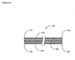
- Figure 1A schematically illustrates an optical coupler.
- Figure 1B schematically illustrates a fiber coupler formed by side polishing two hollow-core photonic bandgapfibers mounted on silica blocks.
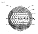
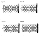
- FIG. 1C schematically illustrates a cross-sectional view of a two-core photonic-bandgap filter (PBF).
- PPF photonic-bandgap filter
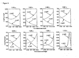
- Figure 7B illustrates the coupling ratios of Figure 7A in the region of 1522 nanometers.
- Figure 7C illustrates the coupling ratios of Figure 7A in the region of 1569 nanometers.
- Figure 7D illustrates the coupling ratios of Figure 7A in the region of 1599 nanometers.
- Figures 8A and 8B illustrate the transmission as a function of wavelength for both polarizations in example two-core PBFs with lengths of 2 millimeters and 3 millimeters, respectively.
- Figure 9 illustrates the x - and y -polarization coupling lengths for various values of the core radius R as functions of wavelength.
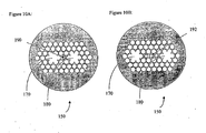
- FIGS 10A and 10B schematically illustrate two example two-core PBFs.
- Figure 11 illustrates the birefringence as a function of the defect radius for the point defect of Figure 10A with a core separation of 4 crystal spatial periods.
- Figure 12 illustrates the birefringence as a function of the defect radius for the point defect of Figure 10A with a core separation of 6 crystal spatial periods.
- Figure 13 illustrates the birefringence as a function of the defect radius for the line defect of Figure 10B with a core separation of 6 crystal spatial periods.
- Figure 1A schematically illustrates an optical coupler 100.
- the optical coupler 100 comprises a first optical port 110, a second optical port 120, a third optical port 130, and a fourth optical port 140.
- the optical coupler 100 further comprises a two-core photonic-bandgap fiber (PBF) 150 comprising a cladding 160, a first core 170, and a second corc 180.
- the first core 170 is optically coupled to the first optical port 110 and to the second optical port 120.
- the second core 180 is optically coupled to the third optical port 130 and to the fourth optical port 140.
- the first optical port 110 comprises a first portion of the first core 170
- the second optical port 120 comprises a second portion of the first core 170.
- the third optical port 130 comprises a first portion of the second core 180
- the fourth optical port 140 comprises a second portion of the second core 180.
- Persons skilled in the art can identify appropriate means or techniques for splicing or butt-coupling the two-core PBF to other portions of an optical system in accordance with certain embodiments described herein.
- Two hollow-core photonic-bandgap fibers can be coupled to each other by using the same technologies developed for coupling solid-core fibers.
- a two-core PBF coupler can be fabricated with two hollow cores, each of which is substantially surrounded by a cladding.
- other technologies can be used to fabricate a hollow two-core PBF coupler, including but not limited to, side-by-side coupling of polished hollow-core PBFs, fusing of two hollow-core PBFs together, and utilizing micro-optic beam splitters.
- Figure 1B schematically illustrates an example fiber coupler 100 formed by side polishing two hollow-core PBFs 102, 104 mounted on silica blocks. Micropositioners can be used to position both hollow-core PBFs 102, 104 together, and by controlling the distance and/or angle of the PBFs 102, 104, a tunable device can be fabricated.
- Figure 1C schematically illustrates a cross-sectional view of the two-core PBF 150 in a plane generally perpendicular to a longitudinal axis of the two-core PBF 150.
- the cladding 160 comprises a material 162 with a first refractive index and regions 164 within the cladding 160.
- the regions 164 have a second refractive index lower than the first refractive index.
- Figure 1B does not show all of the regions 164.
- the first core 170 and the second core 180 are substantially identical to one another ( e.g ., twin-core PBF).
- the material 162 comprises silica, while in certain other embodiments, the material 162 comprises another solid material or a multiplicity of solid materials (e.g ., high-index glasses such as chalcogenides, or polymers such as PMMA). Both of the first core 170 and the second core 180 is hollow. In certain embodiments, the regions 164 are hollow. As used herein, the term "hollow" is used in its broadest sense, including being empty or filled with a gaseous material.
- first core 170, the second core 180, and the regions 164 of certain embodiments are filled with a gaseous second material (e.g ., air), which can be at atmospheric pressure, at higher pressures, or at lower pressures (e.g ., at vacuum).
- a gaseous second material e.g ., air
- the regions 164 of the cladding 160 are compatible with certain embodiments described herein.
- the regions 164 can have circular cross-sections (with radius p), as schematically illustrated by Figure 1B , but other shapes of these regions 164 (e. g., elliptical, hexagonal, non-geometrical, or non-symmetric) are also compatible with certain embodiments described herein.
- the regions 164 each have a respective center and adjacent regions 164 are spaced apart by a center-to-center distance A.
- the regions 164 of the cladding 160 are cylindrical extending along the longitudinal axis of the two-core PBF 150.
- the regions 164 are generally identical to one another and are in a periodic, triangular pattern.
- the regions 164 can be in other patterns (e.g ., hexagonal patterns, square patterns, non-periodic patterns, etc .).
- one or both of the cores 170, 180 has a circular cross-section (with a radius R ), as schematically illustrated by Figure 1B .
- the first core 170 and the second core 180 each have a respective center, and the centers are separated along a lattice vector of the regions 164 of the cladding 160.
- the integer m is even, while in certain other embodiments, the integer m is odd.
- the first and second refractive indices are selected in certain embodiments such that each of the cores 170, 180 supports a guided mode via the photonic-bandgap effect. This implies that the second refractive index of the regions 164 is lower than the first refractive index of the material 162, and that the difference between these indices is large enough to support guided modes.
- neither of the cores 170, 180 comprises a core ring, while in certain other embodiments, one or both of the first core 170 and the second core 180 comprises a core ring.
- Coupling between the first core 170 and the second core 180 can generally be described by either coupled-mode or normal-mode theory.
- coupled-mode theory when light is launched into the fundamental mode of the first core 170, the evanescent field of the light extends into the adjacent second core 180 and excites the fundamental mode of the second core 180, which results in the energy of the light gradually transferring into the second core 180.
- the structure is viewed as a two-core waveguide, which supports four non-degenerate eigenmodes: an even (or symmetric) mode and an odd (or antisymmetric) mode for each of the two orthogonal linear polarizations.
- an even (or symmetric) mode and an odd (or antisymmetric) mode for each of the two orthogonal linear polarizations.
- light of a given polarization is launched into one of the cores 170, 180, it excites the every and odd modes of this polarization with almost equal power. Because these two non-degenerate modes have different phase velocities, as they propagate along the fiber, they accumulate a phase shift.
- the coupling length After a certain length, called the coupling length or beat length, this phase shift reaches ⁇ radians, so the two modes are out of phase from one another, and they interfere destructively in the original core and constructively in the other core.
- the beat length the energy of the light has been coupled from one core to the other core. It can be shown that the beat length is proportional to the reciprocal of the effective index mismatch between the even modes and the odd modes.
- a numerical simulator can be used to calculate the effective indices of the two fundamental eigenmodes supported by the two cores 170, 180.
- Such numerical simulations performed using the Stanford Photonic-Bandgap Fiber (SPBF) code, are described more fully below.
- SPBF Stanford Photonic-Bandgap Fiber
- the numerical simulations used a finite-difference method to solve a vectorial transverse-magnetic-field equation in a matrix form to quickly and accurately calculate the effective index, electric fields, and magnetic fields of the four fundamental eigenmodes of a fiber of arbitrary index profile. ( See, e.g., V.
- twin-core fiber structures have two axes of symmetry: one along a line joining both core centers, (termed the y-axis), and the other along a line orthogonal to the line joining both core centers (termed the x-axis) and formed by the points equidistant from both core centers. Consequently, the modes of a two-core PBF belong to the C 2v point group, and all their modes can be classified in one of four representations, defined as:
- This core radius R corresponds to a structure in which each isolated core 170, 180 is free of surface modes (see, e.g., U.S. Patent No. 7,110,650 , U.S. Patent Application Publication No. 2005/0281522A1 , and H.K. Kim et al., "Designing air-core photonic-bandgap fibers free of surface modes," IEEE J. Quant. Electron., Vol.
- both polarizations exhibit a significant birefringence between the odd and even modes.
- the index difference ⁇ n is approximately 6x10 -4 for the x-polarization and 4x10 -4 for the y- polarization.
- Each representation is quasi-gaussian in the neighborhood of a core center, and it exhibits small side lobes localized on the thicker regions of the cladding material ( e.g., silica) closest to each core.
- the main lobes have the same sign for the two even modes, and opposite signs for the two odd modes.
- the coupling length for x -polarized light is about 1.18 millimeters and for y -polarized light is about 1.59 millimeters.
- Both the x -polarized and y -polarized even modes exhibit some energy localized around the mid-point between the cores. This property is shown in Figures 3C and 3G , but is more readily seen in the logarithmic scale plots of Figures 3D and 3H .
- the closest opposite sidelobes, for both cores, are shown to be linked together in Figure 3D and 3H , resulting in a stronger effective index for the even modes, and decreased coupling length.
- This property results from the presence of a solid membrane at the mid-point, which is surrounded by hollow regions on both sides and thus constitutes a local index-guided waveguide.
- the odd modes carry virtually no energy at the mid-point between the cores, as shown in Figures 3A and 3E . Therefore, the even modes have a larger amount of energy in the solid membrane, which raises their effective index relative to the odd modes.
- the coupling strength can be considerably smaller when there is a hollow region rather than a solid membrane at the center of the fiber.
- This configuration can be accomplished by changing the core spacing from an odd to an even multiple of A.
- the mid-point between both cores is now located at the center of a hollow region of the cladding, and the differences between the intensity profiles of the odd and even modes are much less pronounced.
- the high-index mid-point solid membrane has been replaced by a lower index material (e.g ., air), and the birefringence of all modes is noticeably reduced.
- a lower index material e.g ., air
- the birefringence of all modes is noticeably reduced.
- d 4 ⁇
- the polarization dependence of the coupling length in a two-core PBF is a feature not present in conventional two-core fibers.
- the fields of the two orthogonally polarized fundamental modes differ only very slightly under a 90-degree rotation.
- the mode overlap from one fiber core to the other depends extremely weakly on polarization.
- both solutions for the orthogonal polarizations are deduced from each other through a 90-degree rotation, so both the numerator and the denominator of Equation (2) are polarization-independent.
- the fundamental modes belong to a two-dimensional representation and are not invariant under a 90-degree rotation.
- the field distribution of one polarization mode cannot be derived from the distribution of the other polarization mode through a simple rotation, and the field overlap integral in the numerator of Equation (2) is polarization-dependent.
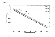
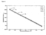
- Figure 6 illustrates the normalized coupling length L C / ⁇ calculated against the normalized wavelength ⁇ / ⁇ for both the x - and y -polarizations and increasing values of the core separation.
- the coupling length increases rapidly ( e.g ., approximately exponentially) as the core separation increases, because the mode energy decreases rapidly away from the center of a given core.
- Two-core PBFs also exhibit different modal behavior than conventional two-core fibers.
- the even mode exhibits a higher effective index than does the odd mode.
- the parity of d / ⁇ determines the modal behavior of the two-core PBF structures.
- the middle point between the two cores is at a hollow region, and for odd values of d/ ⁇ , the middle point between the two cores is located in the solid cladding material.
- the relative positions of the odd and even fundamental core modes of the two-core PBF structure are exchanged, as shown in Figures 2 and 5 .
- the even fundamental mode has a higher effective index than does the odd mode, regardless of polarization, as in the case of a conventional index-guiding two-core fiber.
- the odd fundamental mode has a higher effective index than the even mode for the x-polarization, while that behavior is opposite for the y-polarization.
- the even x-polarized mode of representation A2 shows a linking of the closest sidelobes across the y-axis.
- the even y-polarized mode of representation B2 exhibits some energy located within the solid membrane located at the mid-point.
- the combination of solid material at the mid-point with hollow regions on both sides forms a waveguide locally, and the even modes of the two-core PBF structure can concentrate a larger amount of energy in the solid membrane, thus raising their effective index.
- This observation explains the unique PBF feature of the even modes of the two-core PBF structure having a higher effective index than does the odd modes for odd values of the core-to-core spacing parameter d / ⁇ .
- the mid-point between both cores is located in a hollow region, and the differences between odd and even mode intensity profiles are much smaller.
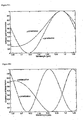
- the two-core PBF can be used as a four-port fiber coupler 100, as schematically illustrated by Figure 1A .
- the optical coupler 100 can be only a few millimeters in length and can provide full coupling between the ports.
- the coupling ratio is plotted for both x - and y -polarized light.
- the optical coupler 100 can be used as a wavelength-division multiplexer with the same input polarization restrictions.
- the wavelength separation between 0 and 100% coupling ranges from about 18 nanometers to about 32 nanometers for the x-polarization, and from about 26 nanometers to about 42 nanometers for the y- polarization.
- the input polarization is advantageously maintained to be stable, for example by circuits using polarization-maintaining fiber.
- the two-core PBF 150 can be used as a polarization-independent directional optical coupler at any of the wavelengths where the two curves of Figure 7A intersect.
- the two-core PBF 150 can be used as an approximately 3-dB fiber coupler at 1584 nanometers (point A of Figure 7A ), and an approximately 100% coupler at 1522 nanometers (point B of Figure 7A ). In the vicinity of point B, the coupling ratio exceeds 90% over a bandwidth of about 5 nanometers. Either the wavelengths or the coupling ratios at the crossing points can be adjusted to desired values by proper selection of the length of the two-core PBF 150.
- the polarization dependence of the two-core PBF 150 can also be exploited to be used as either a fiber polarizer, a polarization splitter at discrete wavelengths, or a polarization sensor.
- a fiber polarizer a polarization splitter at discrete wavelengths
- a polarization sensor a polarization sensor.
- the 10-dB and 20-dB bandwidths are approximately 10 nanometers and 4 nanometers, respectively. Similar bandwidths are obtained at 1599 nanometers (point D of Figure 7A , magnified in Figure 7D ), except that the roles of the polarizations are switched.
- the center wavelengths can be adjusted by selecting the coupler length appropriately.
- Figures 8A and 8B illustrate the transmission as a function of wavelength for both polarizations in example two-core PBFs with lengths of 2 millimeters and 3 millimeters, respectively. Other geometrical parameters can also be adjusted to design a coupler with the desired coupling properties.
- One or both of the cores can have a thin ring of the first material (e.g ., silica) surrounding the core.
- This change may have originated from a modification in the mode field distribution towards the edge of the core when a ring is present, which modifies the overlap between the core modes and thus the coupling.
- the wavelength at which the x -polarization and y- polarization coupling lengths intersect can be selected by tailoring the core radius. This behavior is illustrated by Figure 9 which shows the x- and y-polarization coupling lengths for various values of the core radius R as functions of wavelength.
- the two-core PBF can be used as a broadband polarizer over a range of wavelengths.
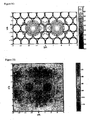
- Figures 10A and 10B schematically illustrate two example two-core PBFs 150. Each of these structures can increase the coupling coefficient for larger core separations.
- Figure 10A schematically illustrates a point defect 190 between the two cores 170, 180.
- Figure 10B schematically illustrates a line defect 192 between the two cores 170, 180 according to an embodiment of the invention.
- the propagation properties of the two-core PBF 150 are strongly affected by the structure of the defect between the two cores 170, 180.
- Figure 11 illustrates the birefringence as a function of the defect radius for a comparative example of the point defect 190 of Figure 10A with a core separation of 4 crystal spatial periods. An increase of the coupling coefficient by about a factor of 20 is possible, and discontinuities due to interactions with surface modes are supported by the defect.
- Figure 12 illustrates the birefringence as a function of the defect radius for the point defect 190 of Figure 10A with a core separation of 6 crystal spatial periods. An increase of the coupling coefficient by about a factor of 10 is possible, and there is a high sensitivity to the defect radius when there are interactions with surface modes.
- Figure 13 illustrates the birefringence as a function of the defect radius for the line defect 192 of Figure 10B according to the invention with a core separation of 6 crystal spatial periods.
- An increase of the coupling coefficient by about a factor of 1000 is possible, and there is a high sensitivity to the defect size in specific areas.
- the two-core PBF s operated at a wavelength at which the transmission Is very strongly dependent on the defect size.
- the signal transmitted through the two-core PBF in certain such embodiments would exhibit a strong variation due to any perturbation of the defect
Landscapes
- Physics & Mathematics (AREA)
- General Physics & Mathematics (AREA)
- Optics & Photonics (AREA)
- Optical Fibers, Optical Fiber Cores, And Optical Fiber Bundles (AREA)
- Optical Integrated Circuits (AREA)
Applications Claiming Priority (2)
| Application Number | Priority Date | Filing Date | Title |
|---|---|---|---|
| US77822906P | 2006-03-02 | 2006-03-02 | |
| PCT/US2007/005535 WO2007100924A1 (en) | 2006-03-02 | 2007-03-02 | Multiple-core photonic-bandgap fiber with coupling between the cores |
Publications (2)
| Publication Number | Publication Date |
|---|---|
| EP1991894A1 EP1991894A1 (en) | 2008-11-19 |
| EP1991894B1 true EP1991894B1 (en) | 2012-12-19 |
Family
ID=38118948
Family Applications (1)
| Application Number | Title | Priority Date | Filing Date |
|---|---|---|---|
| EP07752249A Active EP1991894B1 (en) | 2006-03-02 | 2007-03-02 | Multiple-core photonic-bandgap fiber with coupling between the cores |
Country Status (4)
| Country | Link |
|---|---|
| US (4) | US7551819B2 (enExample) |
| EP (1) | EP1991894B1 (enExample) |
| JP (1) | JP5307558B2 (enExample) |
| WO (1) | WO2007100924A1 (enExample) |
Families Citing this family (21)
| Publication number | Priority date | Publication date | Assignee | Title |
|---|---|---|---|---|
| US7551819B2 (en) | 2006-03-02 | 2009-06-23 | The Board Of Trustees Of The Leland Stanford Junior University | Multiple-core photonic-bandgap fiber with coupling between the cores |
| US7865051B2 (en) * | 2008-07-02 | 2011-01-04 | Ofs Fitel, Llc | Polarization-dependent hollow-core optical fibers |
| WO2010038863A1 (ja) * | 2008-10-03 | 2010-04-08 | 国立大学法人 横浜国立大学 | 非結合系マルチコアファイバ |
| WO2010101776A2 (en) * | 2009-03-02 | 2010-09-10 | Massachusetts Institute Of Technology | Zero group-velocity modes in chalcogenide holey photonic crystal fibers |
| US9195000B2 (en) * | 2009-12-02 | 2015-11-24 | Ofs Fitel, Llc. | Techniques for reducing crosstalk in multicore fibers |
| JP5734443B2 (ja) * | 2010-10-12 | 2015-06-17 | オーエフエス ファイテル,エルエルシー | マルチコアファイバにおけるクロストークを低減するための技術 |
| JP5828516B2 (ja) * | 2012-03-14 | 2015-12-09 | 日本電信電話株式会社 | 偏光子 |
| US9335466B2 (en) | 2012-12-21 | 2016-05-10 | The Board Of Trustees Of The Leland Stanford Junior University | Waveguide apparatuses and methods |
| US9158065B2 (en) | 2013-03-15 | 2015-10-13 | Ofs Fitel, Llc | Hollow core fiber with polarization dependent loss |
| US9417121B1 (en) | 2013-06-04 | 2016-08-16 | James E. Spencer | Methods and apparatuses using optics with aperture for passing optical signals between input and output stages |
| US9240262B1 (en) * | 2014-07-21 | 2016-01-19 | General Electric Company | Systems and methods for distributed pressure sensing |
| US9791619B2 (en) * | 2015-10-06 | 2017-10-17 | General Electric Company | Microstructured optical fibers for gas sensing systems |
| EP3555680B1 (en) | 2016-12-19 | 2023-06-28 | Lawrence Livermore National Security, LLC | Wavelength selective transfer of optical energy |
| US10838149B2 (en) * | 2019-03-05 | 2020-11-17 | Lawrence Livermore National Security, Llc | Dual-core fiber amplifier for separation of thermal and nonlinear effects |
| CN109990727B (zh) * | 2019-05-21 | 2024-09-17 | 中国计量大学 | 一种基于双芯光纤-光子晶体光纤结构的应变传感器 |
| CN111796364A (zh) * | 2020-06-19 | 2020-10-20 | 天津大学 | 一种太赫兹双芯反谐振光纤耦合器 |
| CN112285060A (zh) * | 2020-10-23 | 2021-01-29 | 天津理工大学 | 双芯微结构光纤模间干涉型高灵敏度折射率传感器 |
| CN112859245B (zh) * | 2021-01-15 | 2022-04-15 | 江西师范大学 | 双芯太赫兹光纤耦合器 |
| CN113296183B (zh) * | 2021-05-25 | 2022-03-29 | 北京科技大学 | 一种基于液晶填充的双芯光子晶体光纤偏振分束器 |
| CN113671620B (zh) * | 2021-08-23 | 2022-05-24 | 燕山大学 | 一种单芯保偏色散补偿微结构光纤 |
| CN114111857A (zh) * | 2021-11-16 | 2022-03-01 | 南京信息工程大学 | 一种基于游标效应的光纤fpi级联mi传感装置 |
Citations (1)
| Publication number | Priority date | Publication date | Assignee | Title |
|---|---|---|---|---|
| CN1687808A (zh) * | 2005-04-22 | 2005-10-26 | 南开大学 | 空气传导双芯光子带隙光纤 |
Family Cites Families (25)
| Publication number | Priority date | Publication date | Assignee | Title |
|---|---|---|---|---|
| DE19548048C2 (de) * | 1995-12-21 | 1998-01-15 | Siemens Matsushita Components | Elektronisches Bauelement, insbesondere mit akustischen Oberflächenwellen arbeitendes Bauelement (OFW-Bauelement) |
| US6301420B1 (en) | 1998-05-01 | 2001-10-09 | The Secretary Of State For Defence In Her Britannic Majesty's Government Of The United Kingdom Of Great Britain And Northern Ireland | Multicore optical fibre |
| DE69917776D1 (de) * | 1998-06-09 | 2004-07-08 | Crystal Fibre As Birkerod | Faser mit photonischer bandlücke |
| AU779320B2 (en) * | 1999-04-30 | 2005-01-13 | Spi Lasers Uk Limited | An optical fibre arrangement |
| WO2002014944A1 (en) * | 2000-08-11 | 2002-02-21 | Crystal Fibre A/S | Optical wavelength converter |
| US20020131713A1 (en) * | 2001-01-22 | 2002-09-19 | Yihlih Peng | Tapered fiber holder |
| US6658183B1 (en) * | 2000-10-20 | 2003-12-02 | Lucent Technologies Inc. | Process for fabricating tapered microstructured fiber system and resultant system |
| WO2002084362A1 (en) * | 2001-04-12 | 2002-10-24 | Omniguide Communications Inc. | High index-contrast fiber waveguides and applications |
| US6891992B2 (en) * | 2001-04-13 | 2005-05-10 | Chiral Photonics, Inc. | Configurable add-drop filter utilizing chiral fiber gratings |
| GB0111055D0 (en) * | 2001-05-04 | 2001-06-27 | Blazephotonics Ltd | A method and apparatus relating to optical fibres |
| WO2002101429A2 (en) * | 2001-06-08 | 2002-12-19 | Crystal Fibre A/S | Photonic bandgap fibre, and use thereof |
| US6819845B2 (en) * | 2001-08-02 | 2004-11-16 | Ultradots, Inc. | Optical devices with engineered nonlinear nanocomposite materials |
| US6829421B2 (en) * | 2002-03-13 | 2004-12-07 | Micron Technology, Inc. | Hollow core photonic bandgap optical fiber |
| US6847771B2 (en) * | 2002-06-12 | 2005-01-25 | Corning Incorporated | Microstructured optical fibers and preforms and methods for fabricating microstructured optical fibers |
| US20040061863A1 (en) * | 2002-08-20 | 2004-04-01 | Digonnet Michel J.F. | Fiber optic sensors with reduced noise |
| US7321712B2 (en) * | 2002-12-20 | 2008-01-22 | Crystal Fibre A/S | Optical waveguide |
| US7082242B2 (en) | 2003-01-31 | 2006-07-25 | Corning Incorporated | Multiple core microstructured optical fibers and methods using said fibers |
| US20040161199A1 (en) * | 2003-02-13 | 2004-08-19 | Sung-Koog Oh | Photonic crystal fiber coupler and fabricating method thereof |
| US7567740B2 (en) * | 2003-07-14 | 2009-07-28 | Massachusetts Institute Of Technology | Thermal sensing fiber devices |
| GB2404450A (en) * | 2003-07-26 | 2005-02-02 | Qinetiq Ltd | Variable optical attenuator with movable reflector and hollow core waveguides |
| CA2538750C (en) | 2003-09-12 | 2012-03-27 | The Board Of Trustees Of The Leland Stanford Junior University | Method for configuring air-core photonic-bandgap fibers free of surface modes |
| WO2005111679A1 (en) | 2004-05-08 | 2005-11-24 | The Board Of Trustees Of The Leland Stanford Junior University | Photonic-bandgap fiber with hollow ring |
| US7340140B1 (en) * | 2005-06-07 | 2008-03-04 | The Boeing Company | Er/Yb double clad photonic crystal fiber |
| US7551819B2 (en) * | 2006-03-02 | 2009-06-23 | The Board Of Trustees Of The Leland Stanford Junior University | Multiple-core photonic-bandgap fiber with coupling between the cores |
| US7343074B1 (en) * | 2007-02-27 | 2008-03-11 | Corning Incorporated | Optical waveguide environmental sensor and method of manufacture |
-
2007
- 2007-03-01 US US11/681,019 patent/US7551819B2/en active Active
- 2007-03-02 JP JP2008557429A patent/JP5307558B2/ja active Active
- 2007-03-02 WO PCT/US2007/005535 patent/WO2007100924A1/en not_active Ceased
- 2007-03-02 EP EP07752249A patent/EP1991894B1/en active Active
-
2009
- 2009-05-04 US US12/435,294 patent/US7853107B2/en active Active
-
2010
- 2010-11-08 US US12/941,743 patent/US8094983B2/en active Active
-
2011
- 2011-12-07 US US13/313,264 patent/US8385697B2/en active Active
Patent Citations (1)
| Publication number | Priority date | Publication date | Assignee | Title |
|---|---|---|---|---|
| CN1687808A (zh) * | 2005-04-22 | 2005-10-26 | 南开大学 | 空气传导双芯光子带隙光纤 |
Also Published As
| Publication number | Publication date |
|---|---|
| US20110142397A1 (en) | 2011-06-16 |
| US8094983B2 (en) | 2012-01-10 |
| US20090263090A1 (en) | 2009-10-22 |
| JP2009528575A (ja) | 2009-08-06 |
| JP5307558B2 (ja) | 2013-10-02 |
| EP1991894A1 (en) | 2008-11-19 |
| US20070274652A1 (en) | 2007-11-29 |
| WO2007100924A1 (en) | 2007-09-07 |
| US7551819B2 (en) | 2009-06-23 |
| US7853107B2 (en) | 2010-12-14 |
| US8385697B2 (en) | 2013-02-26 |
| US20120141081A1 (en) | 2012-06-07 |
Similar Documents
| Publication | Publication Date | Title |
|---|---|---|
| EP1991894B1 (en) | Multiple-core photonic-bandgap fiber with coupling between the cores | |
| EP3152607B1 (en) | An anti-resonant hollow-core fiber | |
| Kopp et al. | Chiral fibers: microformed optical waveguides for polarization control, sensing, coupling, amplification, and switching | |
| US9348086B2 (en) | Few-mode optical fibers | |
| Zang et al. | Antiresonant hollow-core inline fiber polarizer | |
| Mousavi et al. | First design of high birefringence and polarising hollow core anti-resonant fibre | |
| Ma et al. | Highly birefringent anti-resonant hollow-core fiber with a low loss | |
| Hao et al. | Optimized design of unsymmetrical gap nodeless hollow core fibers for optofluidic applications | |
| Chiang et al. | Analysis of an ultrashort PCF-based polarization splitter | |
| Jia et al. | Decoupling of dual-hollow-core anti-resonant fiber | |
| Gao et al. | Dual mach-zehnder interferometer based on DCF and FCF for temperature and strain measurement | |
| Saitoh et al. | Tunable photonic crystal fiber couplers with a thermo-responsive liquid crystal resonator | |
| Odoeze et al. | Si-core photonic crystal fiber transverse-electric pass polarizer | |
| US20110317960A1 (en) | Direct coupling of optical slot waveguide to another optical waveguide | |
| Adnan et al. | Fusion splicing: the penalty of increasing the collapse length of the air holes in ESM-12B photonic crystal fibers | |
| Wang et al. | Polarization splitter based on dual-core photonic crystal fiber with octagonal lattice | |
| Zhao et al. | All-fiber low-loss connector for accessing both close cores of twin-core fiber | |
| Podoliak et al. | Dual-core optical fiber as beam splitter with arbitrary, tunable polarization-dependent transfer function | |
| Serrão et al. | A new approach to obtain single-polarization hollow-core photonic bandgap fiber | |
| Cheng et al. | Design of Ultra-low-loss Hollow-core Polarization Maintaining Fibers with Hybrid Nested Semi-tube Geometry | |
| Deng et al. | Low loss silicon microring resonator as comb filter | |
| Birks et al. | Seeing things in a hole new light: photonic crystal fibers | |
| Lin et al. | Influence of cores' shape on the coupling length of dual-core fiber | |
| Plastun et al. | Design of transmission bands in all-solid photonic bandgap fiber | |
| Wang et al. | Guided properties and applications of photonic bandgap fibers |
Legal Events
| Date | Code | Title | Description |
|---|---|---|---|
| PUAI | Public reference made under article 153(3) epc to a published international application that has entered the european phase |
Free format text: ORIGINAL CODE: 0009012 |
|
| 17P | Request for examination filed |
Effective date: 20080925 |
|
| AK | Designated contracting states |
Kind code of ref document: A1 Designated state(s): DE DK FR GB |
|
| RBV | Designated contracting states (corrected) |
Designated state(s): DE DK FR GB |
|
| 17Q | First examination report despatched |
Effective date: 20091207 |
|
| GRAP | Despatch of communication of intention to grant a patent |
Free format text: ORIGINAL CODE: EPIDOSNIGR1 |
|
| DAX | Request for extension of the european patent (deleted) | ||
| GRAS | Grant fee paid |
Free format text: ORIGINAL CODE: EPIDOSNIGR3 |
|
| GRAA | (expected) grant |
Free format text: ORIGINAL CODE: 0009210 |
|
| AK | Designated contracting states |
Kind code of ref document: B1 Designated state(s): DE DK FR GB |
|
| REG | Reference to a national code |
Ref country code: GB Ref legal event code: FG4D |
|
| REG | Reference to a national code |
Ref country code: DE Ref legal event code: R096 Ref document number: 602007027487 Country of ref document: DE Effective date: 20130207 |
|
| PLBE | No opposition filed within time limit |
Free format text: ORIGINAL CODE: 0009261 |
|
| STAA | Information on the status of an ep patent application or granted ep patent |
Free format text: STATUS: NO OPPOSITION FILED WITHIN TIME LIMIT |
|
| PG25 | Lapsed in a contracting state [announced via postgrant information from national office to epo] |
Ref country code: DK Free format text: LAPSE BECAUSE OF FAILURE TO SUBMIT A TRANSLATION OF THE DESCRIPTION OR TO PAY THE FEE WITHIN THE PRESCRIBED TIME-LIMIT Effective date: 20121219 |
|
| 26N | No opposition filed |
Effective date: 20130920 |
|
| REG | Reference to a national code |
Ref country code: DE Ref legal event code: R097 Ref document number: 602007027487 Country of ref document: DE Effective date: 20130920 |
|
| REG | Reference to a national code |
Ref country code: FR Ref legal event code: PLFP Year of fee payment: 10 |
|
| REG | Reference to a national code |
Ref country code: FR Ref legal event code: PLFP Year of fee payment: 11 |
|
| REG | Reference to a national code |
Ref country code: FR Ref legal event code: PLFP Year of fee payment: 12 |
|
| P01 | Opt-out of the competence of the unified patent court (upc) registered |
Effective date: 20230804 |
|
| PGFP | Annual fee paid to national office [announced via postgrant information from national office to epo] |
Ref country code: DE Payment date: 20250319 Year of fee payment: 19 |
|
| PGFP | Annual fee paid to national office [announced via postgrant information from national office to epo] |
Ref country code: FR Payment date: 20250325 Year of fee payment: 19 |
|
| PGFP | Annual fee paid to national office [announced via postgrant information from national office to epo] |
Ref country code: GB Payment date: 20250319 Year of fee payment: 19 |