EP1991790B1 - Ventileinrichtung mit softstartfunktion - Google Patents
Ventileinrichtung mit softstartfunktion Download PDFInfo
- Publication number
- EP1991790B1 EP1991790B1 EP07702979A EP07702979A EP1991790B1 EP 1991790 B1 EP1991790 B1 EP 1991790B1 EP 07702979 A EP07702979 A EP 07702979A EP 07702979 A EP07702979 A EP 07702979A EP 1991790 B1 EP1991790 B1 EP 1991790B1
- Authority
- EP
- European Patent Office
- Prior art keywords
- passage
- valve
- soft
- control slide
- pressure
- Prior art date
- Legal status (The legal status is an assumption and is not a legal conclusion. Google has not performed a legal analysis and makes no representation as to the accuracy of the status listed.)
- Not-in-force
Links
Images


Classifications
-
- F—MECHANICAL ENGINEERING; LIGHTING; HEATING; WEAPONS; BLASTING
- F15—FLUID-PRESSURE ACTUATORS; HYDRAULICS OR PNEUMATICS IN GENERAL
- F15B—SYSTEMS ACTING BY MEANS OF FLUIDS IN GENERAL; FLUID-PRESSURE ACTUATORS, e.g. SERVOMOTORS; DETAILS OF FLUID-PRESSURE SYSTEMS, NOT OTHERWISE PROVIDED FOR
- F15B11/00—Servomotor systems without provision for follow-up action; Circuits therefor
- F15B11/06—Servomotor systems without provision for follow-up action; Circuits therefor involving features specific to the use of a compressible medium, e.g. air, steam
- F15B11/068—Servomotor systems without provision for follow-up action; Circuits therefor involving features specific to the use of a compressible medium, e.g. air, steam with valves for gradually putting pneumatic systems under pressure
-
- F—MECHANICAL ENGINEERING; LIGHTING; HEATING; WEAPONS; BLASTING
- F15—FLUID-PRESSURE ACTUATORS; HYDRAULICS OR PNEUMATICS IN GENERAL
- F15B—SYSTEMS ACTING BY MEANS OF FLUIDS IN GENERAL; FLUID-PRESSURE ACTUATORS, e.g. SERVOMOTORS; DETAILS OF FLUID-PRESSURE SYSTEMS, NOT OTHERWISE PROVIDED FOR
- F15B13/00—Details of servomotor systems ; Valves for servomotor systems
- F15B13/02—Fluid distribution or supply devices characterised by their adaptation to the control of servomotors
- F15B13/06—Fluid distribution or supply devices characterised by their adaptation to the control of servomotors for use with two or more servomotors
- F15B13/08—Assemblies of units, each for the control of a single servomotor only
- F15B13/0803—Modular units
- F15B13/0807—Manifolds
- F15B13/0814—Monoblock manifolds
-
- F—MECHANICAL ENGINEERING; LIGHTING; HEATING; WEAPONS; BLASTING
- F15—FLUID-PRESSURE ACTUATORS; HYDRAULICS OR PNEUMATICS IN GENERAL
- F15B—SYSTEMS ACTING BY MEANS OF FLUIDS IN GENERAL; FLUID-PRESSURE ACTUATORS, e.g. SERVOMOTORS; DETAILS OF FLUID-PRESSURE SYSTEMS, NOT OTHERWISE PROVIDED FOR
- F15B13/00—Details of servomotor systems ; Valves for servomotor systems
- F15B13/02—Fluid distribution or supply devices characterised by their adaptation to the control of servomotors
- F15B13/06—Fluid distribution or supply devices characterised by their adaptation to the control of servomotors for use with two or more servomotors
- F15B13/08—Assemblies of units, each for the control of a single servomotor only
- F15B13/0803—Modular units
- F15B13/0807—Manifolds
- F15B13/0817—Multiblock manifolds
-
- F—MECHANICAL ENGINEERING; LIGHTING; HEATING; WEAPONS; BLASTING
- F15—FLUID-PRESSURE ACTUATORS; HYDRAULICS OR PNEUMATICS IN GENERAL
- F15B—SYSTEMS ACTING BY MEANS OF FLUIDS IN GENERAL; FLUID-PRESSURE ACTUATORS, e.g. SERVOMOTORS; DETAILS OF FLUID-PRESSURE SYSTEMS, NOT OTHERWISE PROVIDED FOR
- F15B13/00—Details of servomotor systems ; Valves for servomotor systems
- F15B13/02—Fluid distribution or supply devices characterised by their adaptation to the control of servomotors
- F15B13/06—Fluid distribution or supply devices characterised by their adaptation to the control of servomotors for use with two or more servomotors
- F15B13/08—Assemblies of units, each for the control of a single servomotor only
- F15B13/0803—Modular units
- F15B13/0832—Modular valves
-
- F—MECHANICAL ENGINEERING; LIGHTING; HEATING; WEAPONS; BLASTING
- F15—FLUID-PRESSURE ACTUATORS; HYDRAULICS OR PNEUMATICS IN GENERAL
- F15B—SYSTEMS ACTING BY MEANS OF FLUIDS IN GENERAL; FLUID-PRESSURE ACTUATORS, e.g. SERVOMOTORS; DETAILS OF FLUID-PRESSURE SYSTEMS, NOT OTHERWISE PROVIDED FOR
- F15B13/00—Details of servomotor systems ; Valves for servomotor systems
- F15B13/02—Fluid distribution or supply devices characterised by their adaptation to the control of servomotors
- F15B13/06—Fluid distribution or supply devices characterised by their adaptation to the control of servomotors for use with two or more servomotors
- F15B13/08—Assemblies of units, each for the control of a single servomotor only
- F15B13/0803—Modular units
- F15B13/0846—Electrical details
- F15B13/085—Electrical controllers
-
- F—MECHANICAL ENGINEERING; LIGHTING; HEATING; WEAPONS; BLASTING
- F15—FLUID-PRESSURE ACTUATORS; HYDRAULICS OR PNEUMATICS IN GENERAL
- F15B—SYSTEMS ACTING BY MEANS OF FLUIDS IN GENERAL; FLUID-PRESSURE ACTUATORS, e.g. SERVOMOTORS; DETAILS OF FLUID-PRESSURE SYSTEMS, NOT OTHERWISE PROVIDED FOR
- F15B13/00—Details of servomotor systems ; Valves for servomotor systems
- F15B13/02—Fluid distribution or supply devices characterised by their adaptation to the control of servomotors
- F15B13/06—Fluid distribution or supply devices characterised by their adaptation to the control of servomotors for use with two or more servomotors
- F15B13/08—Assemblies of units, each for the control of a single servomotor only
- F15B13/0803—Modular units
- F15B13/0846—Electrical details
- F15B13/0857—Electrical connecting means, e.g. plugs, sockets
-
- F—MECHANICAL ENGINEERING; LIGHTING; HEATING; WEAPONS; BLASTING
- F15—FLUID-PRESSURE ACTUATORS; HYDRAULICS OR PNEUMATICS IN GENERAL
- F15B—SYSTEMS ACTING BY MEANS OF FLUIDS IN GENERAL; FLUID-PRESSURE ACTUATORS, e.g. SERVOMOTORS; DETAILS OF FLUID-PRESSURE SYSTEMS, NOT OTHERWISE PROVIDED FOR
- F15B13/00—Details of servomotor systems ; Valves for servomotor systems
- F15B13/02—Fluid distribution or supply devices characterised by their adaptation to the control of servomotors
- F15B13/06—Fluid distribution or supply devices characterised by their adaptation to the control of servomotors for use with two or more servomotors
- F15B13/08—Assemblies of units, each for the control of a single servomotor only
- F15B13/0803—Modular units
- F15B13/0878—Assembly of modular units
- F15B13/0885—Assembly of modular units using valves combined with other components
- F15B13/0892—Valves combined with fluid components
-
- F—MECHANICAL ENGINEERING; LIGHTING; HEATING; WEAPONS; BLASTING
- F15—FLUID-PRESSURE ACTUATORS; HYDRAULICS OR PNEUMATICS IN GENERAL
- F15B—SYSTEMS ACTING BY MEANS OF FLUIDS IN GENERAL; FLUID-PRESSURE ACTUATORS, e.g. SERVOMOTORS; DETAILS OF FLUID-PRESSURE SYSTEMS, NOT OTHERWISE PROVIDED FOR
- F15B13/00—Details of servomotor systems ; Valves for servomotor systems
- F15B13/02—Fluid distribution or supply devices characterised by their adaptation to the control of servomotors
- F15B13/06—Fluid distribution or supply devices characterised by their adaptation to the control of servomotors for use with two or more servomotors
- F15B13/08—Assemblies of units, each for the control of a single servomotor only
- F15B13/0803—Modular units
- F15B13/0878—Assembly of modular units
- F15B13/0896—Assembly of modular units using different types or sizes of valves
-
- F—MECHANICAL ENGINEERING; LIGHTING; HEATING; WEAPONS; BLASTING
- F16—ENGINEERING ELEMENTS AND UNITS; GENERAL MEASURES FOR PRODUCING AND MAINTAINING EFFECTIVE FUNCTIONING OF MACHINES OR INSTALLATIONS; THERMAL INSULATION IN GENERAL
- F16K—VALVES; TAPS; COCKS; ACTUATING-FLOATS; DEVICES FOR VENTING OR AERATING
- F16K27/00—Construction of housing; Use of materials therefor
- F16K27/003—Housing formed from a plurality of the same valve elements
-
- F—MECHANICAL ENGINEERING; LIGHTING; HEATING; WEAPONS; BLASTING
- F15—FLUID-PRESSURE ACTUATORS; HYDRAULICS OR PNEUMATICS IN GENERAL
- F15B—SYSTEMS ACTING BY MEANS OF FLUIDS IN GENERAL; FLUID-PRESSURE ACTUATORS, e.g. SERVOMOTORS; DETAILS OF FLUID-PRESSURE SYSTEMS, NOT OTHERWISE PROVIDED FOR
- F15B2211/00—Circuits for servomotor systems
- F15B2211/30—Directional control
- F15B2211/305—Directional control characterised by the type of valves
- F15B2211/3056—Assemblies of multiple valves
-
- F—MECHANICAL ENGINEERING; LIGHTING; HEATING; WEAPONS; BLASTING
- F15—FLUID-PRESSURE ACTUATORS; HYDRAULICS OR PNEUMATICS IN GENERAL
- F15B—SYSTEMS ACTING BY MEANS OF FLUIDS IN GENERAL; FLUID-PRESSURE ACTUATORS, e.g. SERVOMOTORS; DETAILS OF FLUID-PRESSURE SYSTEMS, NOT OTHERWISE PROVIDED FOR
- F15B2211/00—Circuits for servomotor systems
- F15B2211/30—Directional control
- F15B2211/31—Directional control characterised by the positions of the valve element
- F15B2211/3105—Neutral or centre positions
- F15B2211/3116—Neutral or centre positions the pump port being open in the centre position, e.g. so-called open centre
-
- F—MECHANICAL ENGINEERING; LIGHTING; HEATING; WEAPONS; BLASTING
- F15—FLUID-PRESSURE ACTUATORS; HYDRAULICS OR PNEUMATICS IN GENERAL
- F15B—SYSTEMS ACTING BY MEANS OF FLUIDS IN GENERAL; FLUID-PRESSURE ACTUATORS, e.g. SERVOMOTORS; DETAILS OF FLUID-PRESSURE SYSTEMS, NOT OTHERWISE PROVIDED FOR
- F15B2211/00—Circuits for servomotor systems
- F15B2211/50—Pressure control
- F15B2211/505—Pressure control characterised by the type of pressure control means
- F15B2211/50554—Pressure control characterised by the type of pressure control means the pressure control means controlling a pressure downstream of the pressure control means, e.g. pressure reducing valve
-
- F—MECHANICAL ENGINEERING; LIGHTING; HEATING; WEAPONS; BLASTING
- F15—FLUID-PRESSURE ACTUATORS; HYDRAULICS OR PNEUMATICS IN GENERAL
- F15B—SYSTEMS ACTING BY MEANS OF FLUIDS IN GENERAL; FLUID-PRESSURE ACTUATORS, e.g. SERVOMOTORS; DETAILS OF FLUID-PRESSURE SYSTEMS, NOT OTHERWISE PROVIDED FOR
- F15B2211/00—Circuits for servomotor systems
- F15B2211/50—Pressure control
- F15B2211/52—Pressure control characterised by the type of actuation
- F15B2211/528—Pressure control characterised by the type of actuation actuated by fluid pressure
-
- F—MECHANICAL ENGINEERING; LIGHTING; HEATING; WEAPONS; BLASTING
- F15—FLUID-PRESSURE ACTUATORS; HYDRAULICS OR PNEUMATICS IN GENERAL
- F15B—SYSTEMS ACTING BY MEANS OF FLUIDS IN GENERAL; FLUID-PRESSURE ACTUATORS, e.g. SERVOMOTORS; DETAILS OF FLUID-PRESSURE SYSTEMS, NOT OTHERWISE PROVIDED FOR
- F15B2211/00—Circuits for servomotor systems
- F15B2211/60—Circuit components or control therefor
- F15B2211/605—Load sensing circuits
-
- F—MECHANICAL ENGINEERING; LIGHTING; HEATING; WEAPONS; BLASTING
- F15—FLUID-PRESSURE ACTUATORS; HYDRAULICS OR PNEUMATICS IN GENERAL
- F15B—SYSTEMS ACTING BY MEANS OF FLUIDS IN GENERAL; FLUID-PRESSURE ACTUATORS, e.g. SERVOMOTORS; DETAILS OF FLUID-PRESSURE SYSTEMS, NOT OTHERWISE PROVIDED FOR
- F15B2211/00—Circuits for servomotor systems
- F15B2211/60—Circuit components or control therefor
- F15B2211/635—Circuits providing pilot pressure to pilot pressure-controlled fluid circuit elements
- F15B2211/6355—Circuits providing pilot pressure to pilot pressure-controlled fluid circuit elements having valve means
-
- F—MECHANICAL ENGINEERING; LIGHTING; HEATING; WEAPONS; BLASTING
- F15—FLUID-PRESSURE ACTUATORS; HYDRAULICS OR PNEUMATICS IN GENERAL
- F15B—SYSTEMS ACTING BY MEANS OF FLUIDS IN GENERAL; FLUID-PRESSURE ACTUATORS, e.g. SERVOMOTORS; DETAILS OF FLUID-PRESSURE SYSTEMS, NOT OTHERWISE PROVIDED FOR
- F15B2211/00—Circuits for servomotor systems
- F15B2211/60—Circuit components or control therefor
- F15B2211/67—Methods for controlling pilot pressure
Definitions
- the invention relates to a valve device with soft-start function, comprising a soft-start valve which has main valve means which are able to shut off the connection between a primary channel acted upon by a primary pressure and a secondary channel selectively in a closed position biased by a biasing force or release in an open position, wherein the main valve means for switching to the open position with a soft start pressure can be acted upon, the soft start valve is also able to connect the secondary channel with a separated primary channel with a due to throttling means with respect to the primary pressure at least initially lower soft start pressure acted upon or acted upon soft start channel and wherein the main valve means include a multi-position positionable spool valve capable of connecting the secondary channel to both the soft start channel and the primary channel to control.
- One from the DE 91 05 458 U1 known valve device includes a soft-start valve formed by a 2/2-way valve main valve means which are biased fluidically and by spring force into a closed position in which they shut off the primary channel from the secondary channel.
- a 3/2-way valve is provided, which is able to connect the secondary channel by bridging the 2/2-way valve with a soft start channel, in which due to an associated throttle device as Soft start pressure referred to lower pressure as in the primary channel can prevail.
- the soft start pressure is not only supplied to the secondary channel upon actuation of the 3/2-way valve, but also switched to the main valve means, which are thereby acted upon in the direction of its open position.
- the secondary channel Upon actuation of the 3/2-way valve, the secondary channel is thus supplied with standing under the soft start pressure medium, which due to the gradually increasing soft start pressure after a certain period of time, the main valve means are switched to the open position, so that the secondary channel supplied with full flow from the primary channel becomes.
- a comparably working valve device goes out of the DE 20 2004 015 468 U1 out. There too, the soft-start valve contains two separate valve units for realizing the soft start function.
- a control valve which, to avoid control shocks, causes a gradual fluidization of working channels connected to a consumer.
- the spool is driven to a switching movement with non-uniform velocity, which is achieved by associated throttle slots that takes place at certain transition positions of the spool only a throttled fluid loading of the working channels.
- the US-A-5 038 813 discloses a valve device of the type mentioned, in which a pneumatic valve has a valve member which can selectively connect a secondary channel with a soft start channel or a primary channel and whose switching position is influenced by the prevailing in the soft start soft start pressure, the one Fluid supply to the valve member controlling additional valve is supplied.
- the present invention has for its object to provide a valve device which includes a cost-effective and compact design soft start function.
- the spool is motion-coupled with an actuatable from the soft start pressure opposite to the biasing force also acting on it actuating surface, and that the spool is positionable in a vent position, in which he the secondary channel, with simultaneous separation from the primary channel and from the soft start channel, with a vent channel communicating with the atmosphere.
- the main valve means alone take over the control of the secondary channel with a gradually increasing pressure level.
- a single control valve of the main valve means is able to control the connection of the secondary channel with both the soft start channel and the primary channel and thus allow throttled in a position chargeable as a soft start position and in a workable position as the position under primary pressure full throughput to ensure.
- the control spool is switched over by the soft start pressure applied to it by the intermediary of an actuation surface, which gradually increases during operation due to the gradual filling of the secondary passage until it has reached a level which causes it to switch to the working position.
- the spool can also be positioned in a venting position in addition to the soft start position and the working position, in which he communicates with the secondary channel with a communicating with the atmosphere Venting channel connects.
- this venting position is with respect to the primary channel before a closed position by this is separated by the spool both the secondary channel and the soft start channel.
- the soft start valve Due to the concentration of the relevant for the soft start function valve means in a single valve unit, the soft start valve can be extremely compact and inexpensive realized. It also opens up the possibility of making the soft-start valve so that it can be integrated into a valve manifold equipped with several control valves, in particular by the installation on a mounting surface of a fluid distributor instead of or in addition to a control valve. If necessary, you can even use the valve body of a control valve for the construction of the soft start valve, so that the individual components are reusable, which further reduces the cost of manufacturing and warehousing.
- the valve device can be designed so that the control slide connects in a working position not only the primary channel, but also continues the soft start channel with the secondary channel.
- the soft start channel does not have to be disconnected, but can communicate with the secondary channel parallel to the primary channel. This usually simplifies the design of the soft-start valve.
- the venting preferably takes place through the spool valve. This has for this purpose a in the venting position with on the one hand the secondary channel and on the other hand the vent channel communicating transfer channel.
- the passage through the transfer passage is expediently again controlled separately by a valve member arranged in the control slide. This may obstruct the transfer passage when the spool assumes a position in which fluid leakage is undesirable.
- the valve member may be designed piston-like and rest in the closed position on a stop preferably formed by an associated valve seat, so that it can exert a force on the spool when it is acted upon for purposes of switching the spool back with a control pressure.
- the responsible for the at least initially reduced soft start pressure throttle means are expediently made adjustable in the throttling intensity. They may be an immediate component of the soft-start valve or may be located in a channel of another component of the valve device upstream of the soft-start channel of the soft-start valve, for example in a fluid distributor, when the soft-start valve is mounted on or in such.
- the actuating surface which is preferably arranged directly on the spool valve, can limit an actuating space that can be acted upon by the soft-start pressure in the valve housing of the soft-start valve.
- the soft start pressure is supplied to the actuation space preferably via at least one control channel running at least in sections in the control slide, which is connected to the soft start channel or the secondary channel under the same pressure both in the soft start position and in the work position.
- the operating space is expediently between the actuating slide associated with the actuating surface and one of these opposing stop piston, which is adjustable relative to the spool and also relative to the valve housing. He limited by the interaction with the valve housing the stroke of the spool to specify the soft start position. With subsequent increase of the actuation space switched soft start pressure, it maintains its respect to the valve housing stationary position and allows adjustment of the spool until by associated stop means a stroke limitation takes place, which dictates the working position of the spool.
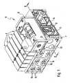
- valve device 6 is designed as a valve battery, which contains a one-piece or, according to the example, modular fluid distributor 7, which is equipped with a plurality of electrically actuated control valves 8.
- control valves 8 are seated in the drawing of them covered mounting surfaces, which open out in the fluid distributor 2 extending channels, which are connected to the valve channels of the control valves 3 in a conventional manner.
- the channels extending in the fluid manifold 7 include a longitudinal manifold feed passage 12 and two parallel first and second manifold vent passages 13, 14. These passages 12, 13, 14 are in fluid communication with each of the control valves 8.
- first and second distributor working channel 15, 16, to the consumer, not shown, can be connected, for example, to be actuated pressure medium drives.
- the fluid loading of the distributor working channels 15, 16 is determined by the control valves 8, which are electrically actuated via an only schematically indicated, running in the fluid distributor 7 electrical signal transmission means 17.
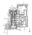
- the fluid distributor 7 is also equipped with a soft start valve 21. Its preferred structure is well visible especially from Figures 3 to 5. It may, for example, be attached to a mounting surface 18 except for the fluid distributor 7, preferably releasably. However, an immediate integration in the fluid distributor 7 would also be possible.
- a first and second distributor supply channel 22, 23 are present, which, however, can also be used as distributor working channels when a control valve 8 is installed on the assembly surface 18 instead of the soft start valve 21.
- a first and second distributor supply channel 22, 23 are present, which, however, can also be used as distributor working channels when a control valve 8 is installed on the assembly surface 18 instead of the soft start valve 21.
- this requires comparable interface dimensions of the control valves 8 and the soft start valve 21 or the interposition of an adapter.
- the distributor feed channel 12 is not supplied with pressure medium in a conventional manner directly via a connection opening from an outer surface of the fluid distributor 7, but via the soft start valve 21.
- the pressure medium in particular compressed air, at the same time via the two manifold supply channels 22, 23 fed and comes from a pressure source, not shown, the two channels 22, 23 provides a pressure medium under a primary pressure available.
- Soft-start valve 21 includes a valve housing 24 having therein designated in its entirety by reference numeral 25 Main valve means.
- the main valve means 25 are activated by an electrically actuated pilot valve 26, which is installed on or in the valve housing 24 and which can be supplied via an electrical interface 27 with the required electrical actuation signals. Deviating from the embodiment provided for, independent of the electrical signal transmission device 17 electrical supply of the pilot valve 26, this may also be connected to the electrical signal transmission device 17 in a modified embodiment.
- valve housing 24 In the interior of the valve housing 24 is a slide receptacle 28 with a therein in the direction of its longitudinal axis 32 slidable spool 33.
- the spool 33 has a special design, which is better expressed by the fact that he in the FIGS. 3 to 5 is shown cut in different sectional planes.
- the slider receptacle 28 is divided into a plurality of axially successive sections belonging to channels, which thus on the Open outside surface of the valve housing 24 that they communicate with the correct allocation with the provided on the mounting surface openings of the distribution channels.
- a secondary channel 1 communicating with the distribution feeder channel 12, around a soft start channel 2 communicating with the first distribution feeder channel 22, around a bleed channel 3 communicating with the first header ventilation channel 13, and around one with the second distributor channel.
- Supply channel 23 communicating primary channel 4.
- Another duct 5 communicates with the second manifold vent 14, but is inoperative. He could also be omitted.
- the primary pressure fed into the second distributor supply channel 23 remains constant at the same level also in the primary channel 4 of the soft start valve 21.
- the pressure prevailing in the soft start channel 2 is variable and is influenced by throttle means 35, which are expediently installed in the course of the first distributor supply channel 22 in the fluid distributor 7. They are in FIG. 2 merely schematically illustrated, wherein it should be mentioned that the throttle means 35 are preferably designed to be adjustable so that the throttling intensity caused by them can be set variably.
- the throttle means 35 By means of the throttle means 35, the pressure medium flowing in via the first distributor supply channel 22 is lowered from the original primary pressure to a lower soft start pressure, in conjunction with a reduced flow rate.
- the throttle means could also be installed directly in the soft start valve 21. Furthermore, it would be possible to provide a separate throttle device which is connected upstream of the first distributor supply channel 22 or which is placed between the soft start valve 21 and the fluid distributor 7.
- the single control slide 33 of the main valve means 25 is position-dependent able to control the connection of the secondary channel 1 with both the soft start channel 2 and the primary channel 4 and preferably also with the vent channel 3. This allows a relatively simple and at the same time compact design of the Soft-start valve 21. The essential details of this will be described below with particular reference to FIGS FIGS. 3 to 5 explained.
- the overall elongated control slide 33 preferably has a cylindrical outer contour, which is graduated in the longitudinal direction, and protrudes with an end-side end section 36 into a pilot control chamber 37 formed in the interior of the valve housing 24. This is acted upon by the associated pilot valve 26 in a conventional manner with under a pilot pressure stationary control pressure medium or vented to the atmosphere.
- An opening into the pilot chamber 37 pilot control channel 38, which is dominated by the particular designed as a solenoid valve, electrically actuated pilot valve 26 is shown dotted in the drawing. It communicates on the inlet side with a distributor pilot passage 42 extending in the fluid distributor 7 or also directly inside the soft start valve 21 with the primary passage 4.
- the prevailing in the pilot chamber 37 pressure acts on the associated end face 43 of the spool 33 and at the same time the bottom surface 44 of an elongated cavity 45 of the spool 33 in the direction of the longitudinal axis of the spool 33 slidably guided and preferably piston-shaped valve member 46th
- the spool 37 is at least partially tubular, wherein the cavity 45 is open towards the end face 43 and the bottom surface 44 points in the direction of the end face 43.
- the valve member 46 is thus constantly exposed to the pressure prevailing in the pilot chamber 37 pressure.
- An arranged on the outer circumference of the valve member 46 annular seal 47 prevents a flow past pressure medium between the valve member 46 and the wall of the spool 33rd
- the valve member 46 is within the cavity 45 between a FIG. 3 resulting open position and one out FIGS. 4 and 5 resulting closed position in the direction of the longitudinal axis 32 relative to the spool 33 slidably. In the closed position, it assumes a position farther from the end face 43, which position is predetermined in that it comes into abutment against a preferably annular stop 48 situated in the cavity 45.
- the open position is defined by a further stop 52, which lies axially opposite the bottom surface 44 and is formed, for example, by a sleeve inserted into the cavity 45 at the end face.
- the valve member 46 is expediently a seat valve member.
- the annular stop 48 in this case forms a with the bottom surface 44 opposite end face of the valve member 46 cooperating annular valve seat 48a, through which the cavity 45 is divided into a lying axially on this and beyond the valve seat 48a cavity portion 45a, 45b.
- the connection between the two cavity sections 45a, 45b is open or closed.
- the two cavity sections 45a, 45b form the passage sections of a transfer passage 53 extending in the spool valve 33, which opens with at least one inlet opening 54 and at least one outlet opening 55 at axially spaced locations to the peripheral outer surface of the spool valve 33.
- the outlet opening 55 is located on the valve member 46 facing side of the valve seat 48a, the inlet opening 54 beyond the valve seat 48a.
- end-side end portion 36 opposite second end-side end portion 56 of the spool 33 is provided with an axially opposite to the end face 43 oriented actuating surface 57. It is expediently ring-shaped and can be formed in particular directly on the spool 33.
- the actuating surface 57 is located on a piston-like actuating portion 58 which is slidably mounted under sealing means 62 caused peripheral seal in a valve housing 24, preferably cylindrical piston receptacle 63.
- the actuating surface 57 axially opposite and therefore upstream of the second end-side end portion 56 of the spool 33 is disposed in the piston seat 63 with respect to the spool 33 a separate stop piston 64. He is also sealed by sealing means 65 to the peripheral wall of the piston seat 63, so that it defines a sealed operating space 66 together with the actuating portion 58.
- the stop piston 64 is displaceable both with respect to the spool 33 and with respect to the valve housing 24 in the axial direction of the spool 33. In the relative movement between the stop piston 46 and the spool 33, the volume of the enclosed operating space 66 changes.
- the operating space 66 and thus the actuating surface 57 can be acted upon and in particular constantly acted upon by the soft start pressure currently prevailing in the soft start channel during operation of the valve device 6.
- This is done via an in FIG. 4 by a dotted line clarified control channel 67, which extends in sections in the spool 33 and opens at least one control pressure tap opening 68 to the outer peripheral surface of the spool 33.
- the control pressure working opening 68 is simultaneously formed by the outlet opening 55. In any case, it is so positioned on the spool 33 that it is in still to be explained switching positions of the spool 33 with the soft start channel 2 or the secondary channel 1 in conjunction. In this way, the same pressure prevails in the operating chamber 66 as in the soft-start channel 2 or in the secondary channel 1.
- stop means 72, 73 By stop means 72, 73, the relative extension movement between the spool 33 and the stopper piston 46 is limited stroke. If the two components move axially away from one another, the stop means 72, 73 which are arranged on the stop piston 46 and on the control slide 33 meet after a certain relative distance and prevent a further relative movement in the sense of an axial removal.
- the piston-side stop means 72 are in the embodiment at the end-side end portion of a preferably cylindrical piston extension 74 of the stop piston 64, which projects to the spool 33 and dipped into a control chamber 66 open towards Steuerschieberaus strictlyung 75 slidably guided.
- the control slide-side stop means 73 are exemplified by the end face of a inserted into the SteuerschieberausEnglishung 75 and in particular pressed stop sleeve 76 is formed, which is an integral part of the spool 33 and the embodiment also carries the operating portion 58.
- the spool 33 in a FIG. 3 be shown in the clear ventilation position. He takes it as far as possible in the direction of the pilot chamber 37 displaced position.
- the venting position is predefined, for example, by the fact that the spool valve 33, with its end face 43 assigned to the pilot control chamber 37, comes into abutment against a valve housing-fixed end wall 78 axially delimiting the pilot control chamber 37.
- the urging means 77 are capable of exerting an urging force 79 indicated by an arrow on the spool valve 33. However, this does not happen directly, but indirectly with the interposition of the stop piston 64. On this act the biasing means 77, which transmits the biasing force 79 by axial contact with the spool 33 on this.
- stop piston 64 and spool 33 take the widest possible approach to one another position.
- the stop piston 64 may in this case rest in particular directly on the actuating surface 57.
- the piston extension 74 is immersed as far as possible in the spool recess 75.
- the power transmission between the stop piston 64 and the spool 33 also take place in that the piston extension 74 rests against the end face of the axially facing base surface of the Steuerschieberaus Principleung 75.
- the biasing means 77 consist in the advantageous embodiment of a pressing spring means 82. It pushes the stopper piston 64 and consequently the spool 33 constantly in the direction of the venting position. Preferably, it dips through the stop piston 64 into the hollow piston extension 74 in order to support itself at one end against the bottom wall 84 and at the other end against a second end wall 83 of the valve housing.
- the second end wall 83 is opposite to the stop piston 64 on the axial side opposite the operating section 58 and thus delimits a loading space 85 receiving the loading means 77.
- the spring means 82 and the biasing means 77 include a in FIG. 3 only schematically dash-dotted lines indicated second pilot valve 26 a, which is able to act on the loading space 85 controlled with pressure medium.
- the fed pressure medium then acts comparable to the spring device 82 on the stop piston 64 and thus shifts the spool 33 in the venting position. In this case, a pressure pulse is sufficient if at the same time the opposite pilot chamber 37 is vented.
- the secondary channel 1 In the venting position of the spool 33, the secondary channel 1 can be vented through the transfer passage 53 to the vent passage 33 and thus to the atmosphere. As a result, the secondary channel 1 is depressurized and in the exemplary embodiment of the distributor feed channel 12 connected thereto. In this way, the entire valve device 6 can be depressurized.
- the vent flow is in FIG. 3 indicated by a dashed line. It is obvious that to ensure the venting function of the transfer channel 53 is arranged so that in the Vent position, the inlet opening 54 communicates with the secondary channel 1 and the outlet opening 55 with the vent channel 3.
- valve member 46 assumes the open position. Since the pilot chamber 37 is vented, the secondary pressure is able to move the valve member 46 and lift off the valve seat 48 a.
- both the soft start channel 2 and the primary channel 4 are shut off by an interaction of the spool 33 with the sealing means 34.
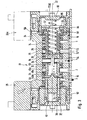
- the pilot pressure is applied by actuation of the pilot valve 26 in the pilot chamber 37. This acts on the spool 33 and displaces it in the direction of the second, end wall 83.
- the effective pressurization surface consists here of the end face 43 of the spool 33 and the bottom surface 44 of the valve member 46 together. The latter is because the pilot pressure shifts the valve member 46 until it rests against the stop 48 or valve seat 48a, thereby introducing the pressure force acting on the valve member 46 into the control slide 33. This condition is clearly visible FIG. 4 ,
- This soft start position is further characterized in that the control slide 33 has established a fluidic connection between the soft start channel 2 and the secondary channel 1.
- pressure medium flows according to the in FIG. 4 dashed line from the soft start channel 2 in the secondary channel 1 via and from the latter example in the distribution feed channel 12 of the valve device. 6
- Another feature of the soft start position is that the spool 33 occupies a closed position with respect to the connection between the secondary channel 1 and primary channel 4. The secondary channel 1 is thus shut off from the primary channel 4. A shut-off of pressure medium between the soft-start channel 2 and the primary channel 4 through the transfer channel 53 is prevented by the valve member 46 held in the closed position due to its fluid loading.
- the soft start pressure in the soft start position and the operating space 66 is supplied, which in FIG. 4 indicated by a dashed line.
- the pressure tap on the positioned in the soft start channel 2 control pressure tap opening 68 is conceivable that this comes to lie in the Softstar too in the region of the secondary channel 1.
- the position is irrelevant because in the soft start channel 2 and in the secondary channel 1 in the soft start position practically the same pressure prevails:
- the operating pressure prevailing in the operating chamber 66 also increases.
- a predetermined level of the operating pressure of the spool 33 switches off in the FIG. 5 apparent working position. This is done against the still existing biasing force 86, with which the spool 33 is acted upon by the located in the pilot chamber 37 control pressure medium.
- the switching to the working position ultimately causing pressure level of the secondary channel 1 can be specified on the area ratios between on the one hand the actuating surface 57 and on the other hand, the end face 43 and the bottom surface 44 and also on the also acting on the biasing force 86 pilot pressure.
- the switching threshold may be at a soft start pressure that is half the primary pressure. However, it is completely free when setting the responsible for switching Softstarttikes.
- the working position of the spool 33 is located axially between the venting position and the soft start position. It is predetermined by the co-operating stop means 72, 73.
- the stop piston 46 - By the pressure building up in the operating chamber 66, the stop piston 46 - compared to the soft start position unchanged - held in a stop position in which it is supported on the second end wall 83 fixed to the housing.
- the actuating portion 58 and with this the entire spool 33 performs a relative movement with respect to the valve housing 24 and the stop piston 64, in which it moves according to arrow 87 in the direction of the venting position, but before reaching this is stopped by the two stop means 72nd , 73 run into each other. This defines the working position.
- the geometry of the spool 33 is selected so that the secondary channel 1 in the working position of the spool 33 according to the in FIG. 5 thinner dashed line also communicates with the soft start channel 2.
- this is not mandatory.
- the working position is maintained as long as in the pilot chamber 37, the pilot pressure is present. If the pilot chamber 37 vented, eliminates the biasing force 86 and the spool 33 is actuated by the biasing means 77 in the already-mentioned venting position FIG. 3 switched back.
- control channel 67 The responsible for the actuation of the actuating surface 57 control channel 67 is connected both in the soft start position and in the working position and during the transition between the two positions with the soft start channel 2 to the required for switching to the working position and maintaining the working position of the pressurization To ensure actuating surface 57.
- a comparison of FIGS. 4 and 5 indicates here that the control pressure tap opening 68 is positioned in each of the aforementioned positions in the region of the soft start channel 2.
- the soft-start valve 21 contains a primary channel 4 charged with a primary pressure, a secondary channel 1 and a soft-start channel 2 acted upon by a throttling means 35 with a soft-start pressure throttled with respect to the primary pressure. Furthermore, it has main valve means 25, by means of which the secondary channel 1 can be connected to the soft-start channel 2 when the primary channel 4 is separated from it and which contains a spool valve 33 which can be positioned in several positions and which counteracts a biasing force 86 from a position separating the primary channel 4 from the secondary channel 1 in a connection releasing the connection between these channels working position can be switched by an actuation surface 57 provided on it from the soft start channel 2 is acted upon by the soft start pressure.
- the spool 33 controls, depending on its position, the connection of the secondary channel 1 with both the primary channel 4 and the soft start channel 2, wherein it is positionable in a soft start channel 2 with the same time separated from the primary channel 4 secondary channel 1 soft start position, from which he on the part of the Soft start pressure occurring admission of the actuating surface 57 can be switched to the working position.
- the soft-start valve 21 integrated into the valve device, a controlled supply and venting of the valve device 6 is possible without recourse to external components. Since the control of the switch positions is caused directly by the pressurization, no electrical pressure sensors are needed.
- the switching function of the soft-start valve 21 can be time-dependent and / or pressure-dependent.
Landscapes
- Engineering & Computer Science (AREA)
- General Engineering & Computer Science (AREA)
- Mechanical Engineering (AREA)
- Physics & Mathematics (AREA)
- Fluid Mechanics (AREA)
- Fluid-Driven Valves (AREA)
- Multiple-Way Valves (AREA)
- Details Of Valves (AREA)
Description
- Die Erfindung betrifft eine Ventileinrichtung mit Softstartfunktion, mit einem Softstartventil, das über Hauptventilmittel verfügt, die in der Lage sind, die Verbindung zwischen einem mit einem Primärdruck beaufschlagten Primärkanal und einem Sekundärkanal wahlweise in einer durch eine Vorspannkraft vorgespannten Schließstellung abzusperren oder in einer Offenstellung freizugeben, wobei die Hauptventilmittel zum Umschalten in die Offenstellung mit einem Softstartdruck beaufschlagbar sind, wobei das Softstartventil ferner in der Lage ist, den Sekundärkanal bei abgetrenntem Primärkanal mit einem auf Grund von Drosselmitteln mit dem gegenüber dem Primärdruck zumindest anfänglich geringeren Softstartdruck beaufschlagten oder beaufschlagbaren Softstartkanal zu verbinden, und wobei die Hauptventilmittel einen in mehreren Stellungen positionierbaren Steuerschieber enthalten, der in der Lage ist, die Verbindung des Sekundärkanals mit sowohl dem Softstartkanal als auch dem Primärkanal zu steuern.
- Eine aus der
DE 91 05 458 U1 bekannte Ventileinrichtung enthält ein Softstartventil mit von einem 2/2-Wegeventil gebildeten Hauptventilmitteln, die fluidisch und durch Federkraft in eine Schließstellung vorgespannt sind, in der sie den Primärkanal vom Sekundärkanal absperren. Zusätzlich zu diesen Hauptventilmitteln ist ein 3/2-Wegeventil vorhanden, das in der Lage ist, den Sekundärkanal unter Überbrückung des 2/2-Wegeventils mit einem Softstartkanal zu verbinden, in dem auf Grund einer zugeordneten Drosseleinrichtung ein als Softstartdruck bezeichneter geringerer Druck wie im Primärkanal herrschen kann. Der Softstartdruck wird bei Betätigung des 3/2-Wegeventils nicht nur dem Sekundärkanal zugeführt, sondern gleichzeitig auch den Hauptventilmitteln aufgeschaltet, die dadurch in Richtung ihrer Offenstellung beaufschlagt werden. Bei Betätigung des 3/2-Wegeventils wird somit der Sekundärkanal mit unter dem Softstartdruck stehendem Druckmedium gespeist, wobei auf Grund des hierbei allmählich steigenden Softstartdruckes nach einer gewissen Zeitspanne die Hauptventilmittel in die Offenstellung geschaltet werden, sodass der Sekundärkanal mit vollem Durchfluss aus dem Primärkanal versorgt wird. - Eine vergleichbar arbeitende Ventileinrichtung geht aus der
DE 20 2004 015 468 U1 hervor. Auch dort enthält das Softstartventil zwei gesonderte Ventileinheiten zur Realisierung der Softstartfunktion. - Aus der
DE 1 283 627 B ist ein Steuerventil bekannt, das zur Vermeidung von Steuerungsschlägen eine allmähliche Fluidbeaufschlagung von Arbeitskanälen hervorruft, die mit einem Verbraucher verbunden sind. Hierzu wird der Steuerschieber zu einer Umschaltbewegung mit ungleichförmiger Geschwindigkeit angetrieben, wobei durch zugeordnete Drosselschlitze erreicht wird, dass bei gewissen Übergangsstellungen des Steuerschiebers eine nur gedrosselte Fluidbeaufschlagung der Arbeitskanäle stattfindet. - Die
US-A-5 038 813 offenbart eine Ventileinrichtung der eingangs genannten Art, bei der ein pneumatisches Ventil ein Ventilglied aufweist, das einen Sekundärkanal wahlweise mit einem Softstartkanal oder einem Primärkanal verbinden kann und dessen Schaltstellung durch den im Softstartkanal herrschenden Softstartdruck beeinflusst wird, der einem die Fluidbeaufschlagung des Ventilgliedes steuernden zusätzlichen Ventil zugeleitet wird. - Die vorliegende Erfindung hat sich zur Aufgabe gestellt, eine Ventileinrichtung zu schaffen, die eine kostengünstige und kompakt bauende Softstartfunktion beinhaltet.
- Zur Lösung dieser Aufgabe ist vorgesehen, dass der Steuerschieber mit einer von dem Softstartdruck entgegengesetzt zu der ebenfalls auf ihn einwirkenden Vorspannkraft beaufschlagbaren Betätigungsfläche bewegungsgekoppelt ist, und dass der Steuerschieber in einer Entlüftungsstellung positionierbar ist, in der er den Sekundärkanal, bei gleichzeitiger Abtrennung vom Primärkanal und vom Softstartkanal, mit einem mit der Atmosphäre kommunizierenden Entlüftungskanal verbindet.
- Somit übernehmen die Hauptventilmittel allein die Ansteuerung des Sekundärkanals mit einem allmählich ansteigenden Druckniveau. Ein einziger Steuerschieber der Hauptventilmittel ist in der Lage, die Verbindung des Sekundärkanals mit sowohl dem Softstartkanal als auch dem Primärkanal zu steuern und somit in einer als Softstartstellung bezeichenbaren Stellung einen gedrosselten Durchsatz zu ermöglichen und in einer als Arbeitsstellung bezeichenbaren Stellung den unter Primärdruck stehenden vollen Durchsatz zu gewährleisten. Umgeschaltet wird der Steuerschieber durch den ihm unter Vermittlung einer Betätigungsfläche aufgeschalteten Softstartdruck, der im Betrieb auf Grund der allmählichen Füllung des Sekundärkanals allmählich ansteigt, bis er ein das Umschalten in die Arbeitsstellung hervorrufendes Niveau erreicht hat. Ein besonderer Vorteil resultiert daraus, dass der Steuerschieber zusätzlich zu der Softstartstellung und der Arbeitsstellung auch noch in einer Entlüftungsstellung positionierbar ist, in der er den Sekundärkanal mit einem mit der Atmosphäre kommunizierenden Entlüftungskanal verbindet. In dieser Entlüftungsstellung liegt bezüglich dem Primärkanal eine Schließstellung vor, indem dieser durch den Steuerschieber sowohl vom Sekundärkanal als auch vom Softstartkanal abgetrennt ist. Somit kann durch das Softstartventil bei Bedarf eine einfache Entlüftung des Sekundärkanals und eines daran eventuell angeschlossenen Verbrauchers vorgenommen werden.
- Durch die Konzentration der für die Softstartfunktion maßgeblich verantwortlichen Ventilmittel in einer einzigen Ventileinheit kann das Softstartventil äußerst kompakt und kostengünstig realisiert werden. Es eröffnet sich zudem die Möglichkeit, das Softstartventil so zu gestalten, dass es sich in eine mit mehreren Steuerventilen ausgestattete Ventilbatterie integrieren lässt, insbesondere durch die Installation an einer Bestückungsfläche eines Fluidverteilers an Stelle eines Steuerventils oder neben einem solchen. Bei Bedarf kann man sogar das Ventilgehäuse eines Steuerventils für den Aufbau des Softstartventils heranziehen, sodass die einzelnen Bauteile mehrfach verwendbar sind, was die Kosten für Fertigung und Lagerhaltung weiter reduziert.
- Vorteilhafte Weiterbildungen der Erfindung gehen aus den Unteransprüchen hervor.
- Die Ventileinrichtung kann so ausgelegt werden, dass der Steuerschieber in einer Arbeitsstellung nicht nur den Primärkanal, sondern weiterhin auch den Softstartkanal mit dem Sekundärkanal verbindet. Der Softstartkanal muss also nicht abgetrennt werden, sondern kann parallel zum Primärkanal mit dem Sekundärkanal kommunizieren. Dies vereinfacht in der Regel die konstruktive Auslegung des Softstartventils.
- Die Entlüftung findet vorzugsweise durch den Steuerschieber hindurch statt. Dieser verfügt zu diesem Zweck über einen in der Entlüftungsstellung mit zum einen dem Sekundärkanal und zum anderen dem Entlüftungskanal kommunizierenden Übertrittskanal.
- Der Durchgang durch den Übertrittskanal ist zweckmäßigerweise nochmals gesondert durch ein im Steuerschieber angeordnetes Ventilglied gesteuert. Dieses kann den Übertrittskanal versperren, wenn der Steuerschieber eine Stellung einnimmt, in der ein Fluidaustritt unerwünscht ist.
- Das Ventilglied kann kolbenartig ausgeführt sein und in der Schließstellung an einem bevorzugt von einem zugeordneten Ventilsitz gebildeten Anschlag anliegen, sodass es eine Stellkraft auf den Steuerschieber ausüben kann, wenn es zu Zwecken des Umschaltens des Steuerschiebers rückseitig mit einem Steuerdruck beaufschlagt wird.
- Die für den zumindest anfänglich reduzierten Softstartdruck verantwortlichen Drosselmittel sind in der Drosselungsintensität zweckmäßigerweise einstellbar ausgeführt. Sie können ein unmittelbarer Bestandteil des Softstartventils sein oder sich in einem dem Softstartkanal des Softstartventils vorgeschalteten Kanal einer weiteren Komponente der Ventileinrichtung befinden, beispielsweise in einem Fluidverteiler, wenn das Softstartventil an oder in einem solchen angebaut bzw. eingebaut ist.
- Die bevorzugt unmittelbar am Steuerschieber angeordnete Betätigungsfläche kann im Ventilgehäuse des Softstartventils einen mit dem Softstartdruck beaufschlagbaren Betätigungsraum begrenzen. Zugeführt wird dem Betätigungsraum der Softstartdruck vorzugsweise über mindestens einen zumindest abschnittsweise im Steuerschieber verlaufenden Steuerkanal, der sowohl in der Softstartstellung als auch in der Arbeitssteglung mit dem Softstartkanal oder dem unter dem gleichen Druck stehenden Sekundärkanal verbunden ist. Dadurch ist eine ständige Aufrechterhaltung einer den Steuerschieber entgegen der Vorspannkraft beaufschlagenden Stellkraft gewährleistet.
- Der Betätigungsraum befindet sich zweckmäßigerweise zwischen der dem Steuerschieber zugeordneten Betätigungsfläche und einem dieser gegenüberliegenden Anschlagkolben, der relativ zum Steuerschieber und auch relativ zum Ventilgehäuse verstellbar ist. Er begrenzt durch das Zusammenwirken mit dem Ventilgehäuse den Hubweg des Steuerschiebers zur Vorgabe der Softstartstellung. Bei anschließender Erhöhung des dem Betätigungsraum aufgeschalteten Softstartdruckes behält er seine bezüglich dem Ventilgehäuse ortsfeste Position bei und ermöglicht ein Verstellen des Steuerschiebers, bis durch zugeordnete Anschlagmittel eine Hubbegrenzung stattfindet, die die Arbeitsstellung des Steuerschiebers vorgibt.
- Nachfolgend wird die Erfindung anhand der beiliegend Zeichnung näher erläutert. In dieser zeigen:
- Figur 1
- in perspektivischer Darstellung eine bevorzugte Ausführungsform der mit einem Softstartventil aus- gestatteten erfindungsgemäßen Ventileinrichtung,
- Figur 2
- die Ventileinrichtung aus
Figur 1 im Bereich des Softstartventils im Querschnitt gemäß Schnittlinie II-II, - Figur 3
- das bei der Anordnung gemäß
Figuren 1 und2 einge- setzte Softstartventil in einer vergrößerten Ein- zeldarstellung im Längsschnitt unter Einnahme der Entlüftungsstellung, - Figur 4
- das Softstartventil aus
Figur 3 unter Einnahme der Softstartstellung, und - Figur 5
- das Softstartventil der
Figuren 3 und4 unter Ein- nahme der Arbeitsstellung. - Die aus
Figuren 1 und2 ersichtliche Ventileinrichtung 6 ist als Ventilbatterie ausgebildet, die einen einstückigen oder, beispielsgemäß, modularen Fluidverteiler 7 enthält, der mit einer Mehrzahl von elektrisch betätigbaren Steuerventilen 8 bestückt ist. - Die Steuerventile 8 sitzen auf in der Zeichnung von ihnen abgedeckten Bestückungsflächen, an denen im Fluidverteiler 2 verlaufende Kanäle ausmünden, die mit den Ventilkanälen der Steuerventile 3 in an sich bekannter Weise verbunden sind.
- Die im Fluidverteiler 7 verlaufenden Kanäle enthalten einen in Längsrichtung verlaufenden Verteiler-Speisekanal 12 sowie zwei dazu parallele erste bzw. zweite Verteiler-Entlüftungskanäle 13, 14. Diese Kanäle 12, 13, 14 stehen mit jedem der Steuerventile 8 in Fluidverbindung.
- Von jedem Bestückungsplatz gehen außerdem ein erster und zweiter Verteiler-Arbeitskanal 15, 16 ab, an die nicht näher dargestellte Verbraucher anschließbar sind, beispielsweise zu betätigende Druckmittelantriebe. Die Fluidbeaufschlagung der Verteiler-Arbeitskanäle 15, 16 wird von den Steuerventilen 8 vorgegeben, die über eine nur schematisch angedeutete, im Fluidverteiler 7 verlaufende elektrische Signalübertragungseinrichtung 17 elektrisch ansteuerbar sind.
- Der Fluidverteiler 7 ist auch mit einem Softstartventil 21 ausgestattet. Dessen bevorzugter Aufbau ist vor allem aus Figuren 3 bis 5 gut ersichtlich. Es kann beispielsweise an einer Bestückungsfläche 18 außer am Fluidverteiler 7, bevorzugt lösbar, angebracht sein. Eine unmittelbare Integration in den Fluidverteiler 7 wäre jedoch ebenfalls möglich.
- An der Bestückungsfläche 18 findet sich eine vergleichbare Konstellation von Mündungen der im Fluidverteiler 7 verlaufenden Kanäle, wie an den Bestückungsflächen für die Steuerventile 8. An der Bestückungsfläche 18 münden also der Verteiler-Speisekanal 12 und die beiden Verteiler-Entlüftungskanäle 13, 14 aus. An Stelle zweier Verteiler-Arbeitskanäle sind jedoch ein erster und zweiter Verteiler-Versorgungskanal 22, 23 vorhanden, die jedoch auch als Verteiler-Arbeitskanäle nutzbar sind, wenn an der Bestückungsfläche 18 an Stelle des Softstartventils 21 ein Steuerventil 8 installiert wird. Umgekehrt besteht ebenso die Möglichkeit, mindestens eine der mit einem Steuerventil 8 bestückten Bestückungsflächen alternativ zu einem Steuerventil 8 mit einem Softstartventil 21 zu bestücken, wobei dann die zugeordneten Verteiler-Arbeitskanäle 15, 16 als Verteiler-Versorgungskanäle 22, 23 genutzt werden. Dies setzt jedoch vergleichbare Schnittstellenabmessungen der Steuerventile 8 und des Softstartventils 21 voraus oder die Zwischenschaltung eines Adapters.
- Mit Hilfe des Softstartventils 21 ist es möglich, bei Inbetriebnahme der Ventileinrichtung 6 einen langsamen, sanften Druckaufbau in dem die Steuerventile 8 versorgenden Verteiler-Speisekanal 12 hervorzurufen. Der Verteiler-Speisekanal 12 wird nicht in konventioneller Weise direkt über eine Anschlussöffnung von einer Außenfläche des Fluidverteilers 7 her mit Druckmedium versorgt, sondern über das Softstartventil 21 hinweg. Das Druckmedium, insbesondere Druckluft, ist gleichzeitig über die beiden Verteiler-Versorgungskanäle 22, 23 einspeisbar und stammt von einer nicht näher dargestellten Druckquelle, die beiden Kanälen 22, 23 ein unter einem Primärdruck stehendes Druckmedium zur Verfügung stellt.
- Das Softstartventil 21 enthält ein Ventilgehäuse 24 mit darin befindlichen, in ihrer Gesamtheit mit Bezugsziffer 25 bezeichneten Hauptventilmitteln. Aktiviert werden die Hauptventilmittel 25 durch ein elektrisch betätigbares Vorsteuerventil 26, das an oder in das Ventilgehäuse 24 eingebaut ist und das über eine elektrische Schnittstelle 27 mit den erforderlichen elektrischen Betätigungssignalen versorgt werden kann. Abweichend von der beim Ausführungsbeispiel vorgesehenen, von der elektrischen Signalübertragungseinrichtung 17 unabhängigen elektrischen Versorgung des Vorsteuerventils 26, kann dieses bei einer abgewandelten Ausführungsform auch an die elektrische Signalübertragungseinrichtung 17 angeschlossen sein.
- Im Innern des Ventilgehäuses 24 befindet sich eine Schieberaufnahme 28 mit einem darin in Richtung seiner Längsachse 32 verschiebbaren Steuerschieber 33. Der Steuerschieber 33 hat eine besondere Gestaltung, die dadurch besser zum Ausdruck kommt, dass er in den
Figuren 3 bis 5 in unterschiedlichen Schnittebenen geschnitten dargestellt ist. - Durch Abdichtmittel 34, die beispielhaft aus mehreren mit axialem Abstand zueinander angeordneten ringförmigen Dichtelementen bestehen, welche den Steuerschieber 33 koaxial umschließen und die gehäusefest fixiert sind, wird die Schieberaufnahme 28 in eine Mehrzahl axial aufeinanderfolgender Abschnitte unterteilt, die zu Kanälen gehören, welche so an der Außenfläche des Ventilgehäuses 24 ausmünden, dass sie zuordnungsrichtig mit den an der Bestückungsfläche vorgesehenen Mündungen der Verteilerkanäle kommunizieren. Im Einzelnen handelt es sich um einen mit dem Verteiler-Speisekanal 12 kommunizierenden Sekundärkanal 1, um einen mit dem ersten Verteiler-Versorgungskanal 22 kommunizierenden Softstartkanal 2, um einen mit dem ersten Verteiler-Entlüftungskanal 13 kommunizierenden Entlüftungskanal 3 und um einen mit dem zweiten Verteiler-Versorgungskanal 23 kommunizierenden Primärkanal 4. Ein weiterer Kanal 5 steht mit dem zweiten Verteiler-Entlüftungskanal 14 in Verbindung, ist jedoch funktionslos. Er könnte auch entfallen.
- Im Betrieb der Ventileinrichtung 6 liegt der in den zweiten Verteiler-Versorgungskanal 23 eingespeiste Primärdruck in unveränderter Höhe konstant auch im Primärkanal 4 des Softstartventils 21 an. Der im Softstartkanal 2 herrschende Druck hingegen ist variabel und wird von Drosselmitteln 35 beeinflusst, die zweckmäßigerweise in den Verlauf des ersten Verteiler-Versorgungskanals 22 im Fluidverteiler 7 eingebaut sind. Sie sind in
Figur 2 lediglich schematisch abgebildet, wobei zu erwähnen ist, dass die Drosselmittel 35 bevorzugt einstellbar ausgebildet sind, sodass sich die von ihnen hervorgerufene Drosselungsintensität variabel vorgeben lässt. Durch die Drosselmittel 35 wird das über den ersten Verteiler-Versorgungskanal 22 zuströmende Druckmedium vom ursprünglichen Primärdruck auf einen diesbezüglich niedrigeren Softstartdruck abgesenkt, in Verbindung mit einem reduzierten Durchfluss. - In nicht näher dargestellter Weise könnten die Drosselmittel auch direkt in das Softstartventil 21 eingebaut sein. Ferner wäre es möglich, eine gesonderte Drosseleinrichtung vorzusehen, die dem ersten Verteiler-Versorgungskanal 22 vorgeschaltet ist oder die zwischen dem Softstartventil 21 und dem Fluidverteiler 7 platziert ist.
- Im Betrieb der Ventileinrichtung 6 ist der einzige Steuerschieber 33 der Hauptventilmittel 25 stellungsabhängig in der Lage, die Verbindung des Sekundärkanals 1 mit sowohl dem Softstartkanal 2 als auch dem Primärkanal 4 und vorzugsweise auch mit dem Entlüftungskanal 3 zu steuern. Dies ermöglicht einen relativ einfachen und zugleich kompakten Aufbau des Softstartventils 21. Wesentliche Details hierzu werden nachfolgend vor allem unter Bezugnahme auf die
Figuren 3 bis 5 erläutert. - Der insgesamt längliche Steuerschieber 33 hat bevorzugt eine zylindrische, in Längsrichtung mehrfach abgestufte Außenkontur und ragt mit einem stirnseitigen Endabschnitt 36 in eine im Innern des Ventilgehäuses 24 ausgebildete Vorsteuerkammer 37 hinein. Diese ist über das zugeordnete Vorsteuerventil 26 in an sich bekannter Weise mit unter einem Vorsteuerdruck stehendem Steuerdruckmedium beaufschlagbar oder an die Atmosphäre entlüftbar. Ein in die Vorsteuerkammer 37 einmündender Vorsteuerkanal 38, der von dem insbesondere als Magnetventil ausgebildeten, elektrisch betätigbaren Vorsteuerventil 26 beherrscht wird, ist in der Zeichnung gepunktet abgebildet. Er kommuniziert einlassseitig mit einem im Fluidverteiler 7 verlaufenden Verteiler-Vorsteuerkanal 42 oder auch direkt im Innern des Softstartventils 21 mit dem Primärkanal 4.
- Der in der Vorsteuerkammer 37 herrschende Druck beaufschlagt die zugeordnete Stirnfläche 43 des Steuerschiebers 33 sowie gleichzeitig die Bodenfläche 44 eines in einem länglichen Hohlraum 45 des Steuerschiebers 33 in Richtung der Längsachse des Steuerschiebers 33 verschiebbar geführten und vorzugsweise kolbenförmig ausgebildeten Ventilgliedes 46.
- Zur Bildung des Hohlraumes 45 ist der Steuerschieber 37 zumindest partiell rohrförmig ausgebildet, wobei der Hohlraum 45 zur Stirnfläche 43 hin offen ist und die Bodenfläche 44 in Richtung der Stirnfläche 43 weist. Das Ventilglied 46 ist somit ständig dem in der Vorsteuerkammer 37 herrschenden Druck ausgesetzt. Eine am Außenumfang des Ventilgliedes 46 angeordnete ringförmige Dichtung 47 verhindert ein Vorbeiströmen von Druckmedium zwischen dem Ventilglied 46 und der Wandung des Steuerschiebers 33.
- Das Ventilglied 46 ist innerhalb des Hohlraumes 45 zwischen einer aus
Figur 3 hervorgehenden Offenstellung und einer ausFiguren 4 und5 hervorgehenden Schließstellung in der Richtung der Längsachse 32 relativ zum Steuerschieber 33 verschiebbar. In der Schließstellung nimmt es eine von der Stirnfläche 43 weiter entfernte Position ein, die dadurch vorgegeben ist, dass es an einem im Hohlraum 45 befindlichen, bevorzugt ringförmigen Anschlag 48 zur Anlage gelangt. Die Offenstellung wird durch einen weiteren Anschlag 52 definiert, der der Bodenfläche 44 axial gegenüber liegt und beispielsweise von einer stirnseitig in den Hohlraum 45 eingesetzten Hülse gebildet wird. - Bei dem Ventilglied 46 handelt es sich zweckmäßigerweise um ein Sitzventilglied. Der ringförmige Anschlag 48 bildet hierbei einen mit der der Bodenfläche 44 entgegengesetzten Stirnfläche des Ventilgliedes 46 kooperierenden ringförmigen Ventilsitz 48a, durch den der Hohlraum 45 in einen axial diesseits und jenseits des Ventilsitzes 48a liegenden Hohlraumabschnitt 45a, 45b unterteilt ist. Je nach Stellung des Ventilgliedes 46 ist die Verbindung zwischen den beiden Hohlraumabschnitten 45a, 45b offen oder geschlossen.
- Die beiden Hohlraumabschnitte 45a, 45b bilden die Kanalabschnitte eines im Steuerschieber 33 verlaufenden Übertrittskanals 53, der mit mindestens einer Eintrittsöffnung 54 und mindestens einer Austrittsöffnung 55 an axial beabstandeten Stellen zur peripheren Außenfläche des Steuerschiebers 33 ausmündet. Die Austrittsöffnung 55 liegt auf der dem Ventilglied 46 zugewandten Seite des Ventilsitzes 48a, die Eintrittsöffnung 54 jenseits des Ventilsitzes 48a.
- An seinem dem oben erwähnten stirnseitigen Endabschnitt 36 entgegengesetzten zweiten stirnseitigen Endabschnitt 56 ist der Steuerschieber 33 mit einer axial entgegengesetzt zu der Stirnfläche 43 orientierten Betätigungsfläche 57 versehen. Sie ist zweckmäßigerweise ringförmig gestaltet und kann insbesondere unmittelbar am Steuerschieber 33 ausgebildet sein.
- Bevorzugt findet sich die Betätigungsfläche 57 an einem kolbenartigen Betätigungsabschnitt 58, der unter von Dichtmitteln 62 hervorgerufener peripherer Abdichtung in einer im Ventilgehäuse 24 ausgebildeten, bevorzugt zylindrischen Kolbenaufnahme 63 verschiebbar gelagert ist.
- Der Betätigungsfläche 57 axial gegenüberliegend und mithin dem zweiten stirnseitigen Endabschnitt 56 des Steuerschiebers 33 axial vorgelagert ist in der Kolbenaufnahme 63 ein bezüglich dem Steuerschieber 33 separater Anschlagkolben 64 angeordnet. Auch er ist durch Dichtmittel 65 zur peripheren Wandung der Kolbenaufnahme 63 abgedichtet, sodass er zusammen mit dem Betätigungsabschnitt 58 einen abgedichteten Betätigungsraum 66 begrenzt.
- Der Anschlagkolben 64 ist sowohl bezüglich dem Steuerschieber 33 als auch bezüglich dem Ventilgehäuse 24 in der Achsrichtung des Steuerschiebers 33 verschiebbar. Bei der Relativbewegung zwischen dem Anschlagkolben 46 und dem Steuerschieber 33 ändert sich das Volumen des eingeschlossenen Betätigungsraumes 66.
- Der Betätigungsraum 66 und mithin die Betätigungsfläche 57 ist mit dem im Betrieb der Ventileinrichtung 6 momentan im Softstartkanal herrschenden Softstartdruck beaufschlagbar und insbesondere ständig beaufschlagt. Dies geschieht über einen in
Figur 4 durch eine gepunktete Linie verdeutlichten Steuerkanal 67, der abschnittsweise im Steuerschieber 33 verläuft und über mindestens eine Steuerdruck-Abgriffsöffnung 68 zur Außenumfangsfläche des Steuerschiebers 33 ausmündet. Zweckmäßigerweise wird die Steuerdruckarbeitsöffnung 68 gleichzeitig von der Austrittsöffnung 55 gebildet. Jedenfalls ist sie so am Steuerschieber 33 positioniert, dass sie bei noch zu erläuternden Schaltstellungen des Steuerschiebers 33 mit dem Softstartkanal 2 oder dem Sekundärkanal 1 in Verbindung steht. Auf diese Weise herrscht im Betätigungsraum 66 der gleiche Druck wie im Softstartkanal 2 bzw. im Sekundärkanal 1. - Durch Anschlagmittel 72, 73 wird die relative Ausfahrbewegung zwischen dem Steuerschieber 33 und dem Anschlagkolben 46 hubmäßig begrenzt. Bewegen sich die beiden Komponenten axial voneinander weg, treffen nach einer gewissen relativen Wegstrecke die zum einen am Anschlagkolben 46 und zum anderen am Steuerschieber 33 angeordneten Anschlagmittel 72, 73 aufeinander und unterbinden eine weitere Relativbewegung im Sinne eines sich axial voneinander Entfernens.
- Die kolbenseitigen Anschlagmittel 72, beispielsweise in Gestalt einer Anschlagscheibe, befinden sich beim Ausführungsbeispiel am stirnseitigen Endabschnitt eines bevorzugt zylindrischen Kolbenfortsatzes 74 des Anschlagkolbens 64, der zum Steuerschieber 33 ragt und in eine zum Betätigungsraum 66 hin offene Steuerschieberausnehmung 75 verschiebbar geführt eintaucht. Die steuerschieberseitigen Anschlagmittel 73 sind beispielhaft von der Stirnfläche einer in die Steuerschieberausnehmung 75 eingesetzten und insbesondere eingepressten Anschlaghülse 76 gebildet, die ein fester Bestandteil des Steuerschiebers 33 ist und die beim Ausführungsbeispiel auch den Betätigungsabschnitt 58 trägt.
- Durch Beaufschlagungsmittel 77 kann der Steuerschieber 33 in einer aus
Figur 3 ersichtlichen Entlüftungsstellung positioniert werden. Er nimmt dabei seine weitest möglich in Richtung der Vorsteuerkammer 37 verlagerte Stellung ein. Vorgegeben wird die Entlüftungsstellung beispielsweise dadurch, dass der Steuerschieber 33 mit seiner der Vorsteuerkammer 37 zugeordneten Stirnfläche 43 an einer die Vorsteuerkammer 37 axial begrenzenden ventilgehäusefesten Abschlusswand 78 zur Anlage gelangt. - Die Beaufschlagungsmittel 77 sind in der Lage, eine durch einen Pfeil angedeutete Beaufschlagungskraft 79 auf den Steuerschieber 33 auszuüben. Dies geschieht jedoch nicht unmittelbar, sondern mittelbar unter Zwischenschaltung des Anschlagkolbens 64. Auf diesen wirken die Beaufschlagungsmittel 77 ein, der die Beaufschlagungskraft 79 durch axiale Anlage am Steuerschieber 33 auf diesen überträgt. Hierbei nehmen Anschlagkolben 64 und Steuerschieber 33 die weitest möglich aneinander angenäherte Stellung ein. Der Anschlagkolben 64 kann hierbei insbesondere unmittelbar an der Betätigungsfläche 57 anliegen. Gleichzeitig ist der Kolbenfortsatz 74 weitest möglich in die Steuerschieberausnehmung 75 eingetaucht. Alternativ oder zusätzlich kann die Kraftübertragung zwischen dem Anschlagkolben 64 und dem Steuerschieber 33 auch dadurch erfolgen, dass der Kolbenfortsatz 74 stirnseitig an der ihm axial zugewandten Grundfläche der Steuerschieberausnehmung 75 anliegt.
- Der besseren Unterscheidung wegen sei die vorgenannte Relativposition zwischen Anschlagkolben 64 und Steuerschieber 33 im Folgenden auch als einander maximal angenäherte Position bezeichnet.
- Die Beaufschlagungsmittel 77 bestehen bei dem vorteilhaften Ausführungsbeispiel aus einer drückenden Federeinrichtung 82. Sie drückt den Anschlagkolben 64 und mithin den Steuerschieber 33 ständig in Richtung der Entlüftungsstellung. Bevorzugt taucht sie durch den Anschlagkolben 64 hindurch in den hohlen Kolbenfortsatz 74 ein, um sich einenends an dessen Bodenwand 84 und andernends an einer zweiten Abschlusswand 83 des Ventilgehäuses abzustützen. Die zweite Abschlusswand 83 liegt dem Anschlagkolben 64 auf der dem Betätigungsabschnitt 58 entgegengesetzten Axialseite gegenüber und begrenzt so einen die Beaufschlagungsmittel 77 aufnehmenden Beaufschlagungsraum 85.
- Bei einer alternativen Ausführungsform entfällt die Federeinrichtung 82 und die Beaufschlagungsmittel 77 umfassen ein in
Figur 3 nur schematisch strichpunktiert angedeutetes zweites Vorsteuerventil 26a, das in der Lage ist, den Beaufschlagungsraum 85 gesteuert mit Druckmedium zu beaufschlagen. Das eingespeiste Druckmedium wirkt dann vergleichbar der Federeinrichtung 82 auf den Anschlagkolben 64 und verschiebt somit den Steuerschieber 33 in die Entlüftungsstellung. Hierbei genügt ein Druckimpuls, wenn gleichzeitig die entgegengesetzte Vorsteuerkammer 37 entlüftet ist. - In der Entlüftungsstellung des Steuerschiebers 33 kann der Sekundärkanal 1 durch den Übertrittskanal 53 hindurch zum Entlüftungskanal 33 und somit zur Atmosphäre entlüftet werden. Dadurch wird der Sekundärkanal 1 drucklos und beim Ausführungsbeispiel der daran angeschlossene Verteiler-Speisekanal 12. Man kann auf diese Weise die gesamte Ventileinrichtung 6 drucklos schalten. Die Entlüftungsströmung ist in
Figur 3 durch eine gestrichelte Linie angedeutet. Es ist offensichtlich, dass zur Gewährleistung der Entlüftungsfunktion der Übertrittskanal 53 so angeordnet ist, dass in der Entlüftungsstellung die Eintrittsöffnung 54 mit dem Sekundärkanal 1 und die Austrittsöffnung 55 mit dem Entlüftungskanal 3 kommuniziert. - Während der Entlüftungsphase nimmt das Ventilglied 46 die Offenstellung ein. Da die Vorsteuerkammer 37 entlüftet ist, ist der Sekundärdruck in der Lage, das Ventilglied 46 zu verschieben und vom Ventilsitz 48a abzuheben.
- In der Entlüftungsstellung des Steuerschiebers 33 sind sowohl der Softstartkanal 2 als auch der Primärkanal 4 durch ein Zusammenwirken des Steuerschiebers 33 mit den Abdichtmitteln 34 abgesperrt.
- Um das Softstartventil 21 zu aktivieren und einen allmählichen Druckaufbau im Sekundärkanal 1 herbeizuführen, wird durch Betätigung des Vorsteuerventils 26 in der Vorsteuerkammer 37 der Vorsteuerdruck angelegt. Dieser beaufschlagt den Steuerschieber 33 und verlagert ihn in Richtung zu der zweiten,Abschlusswand 83. Die wirksame Druckbeaufschlagungsfläche setzt sich hierbei aus der Stirnfläche 43 des Steuerschiebers 33 und der Bodenfläche 44 des Ventilglieds 46 zusammen. Letzteres deshalb, weil der Vorsteuerdruck das Ventilglied 46 bis zur Anlage an dem Anschlag 48 bzw. Ventilsitz 48a verschiebt und dadurch die auf das Ventilglied 46 einwirkende Druckkraft in den Steuerschieber 33 eingeleitet wird. Gut ersichtlich ist dieser Zustand aus
Figur 4 . - Bei dieser Umschaltbewegung schiebt der Steuerschieber 33 den Anschlagkolben 64 entgegen der Beaufschlagungskraft 79 vor sich her, bis der Anschlagkolben 64 an der zweiten Abschlusswand 83 anschlägt. Beim Ausführungsbeispiel ist dies mit einer Komprimierung der Federeinrichtung 82 verbunden. Steuerschieber 33 und Anschlagkolben 46 befinden sich dabei noch immer in der einander maximal angenäherten Position.
- Die aus dieser Umschaltbewegung letztlich resultierende Stellung des Steuerschiebers 33 geht aus
Figur 4 hervor und sei als Softstartstellung bezeichnet. Diese Softstartstellung zeichnet sich weiters dadurch aus, dass der Steuerschieber 33 eine fluidische Verbindung zwischen dem Softstartkanal 2 und dem Sekundärkanal 1 hergestellt hat. Somit strömt Druckmedium gemäß der inFigur 4 gestrichelten Linie aus dem Softstartkanal 2 in den Sekundärkanal 1 über und von letzterem beispielhaft in den Verteiler-Speisekanal 12 der Ventileinrichtung 6. - Ein weiteres Merkmal der Softstartstellung besteht darin, dass der Steuerschieber 33 bezüglich der Verbindung zwischen Sekundärkanal 1 und Primärkanal 4 eine Schließstellung einnimmt. Der Sekundärkanal 1 ist also vom Primärkanal 4 abgesperrt. Ebenfalls abgesperrt ist der Entlüftungskanal 3. Ein Übertritt von Druckmedium zwischen dem Softstartkanal 2 und dem Primärkanal 4 durch den Übertrittskanal 53 hindurch wird durch das auf Grund seiner Fluidbeaufschlagung in der Schließstellung gehaltene Ventilglied 46 verhindert.
- Durch die Verbindung zwischen Softstartkanal 2 und Sekundärkanal 1 baut sich in letzterem allmählich ein zunehmend höherer Softstartdruck auf. Dieser kann theoretisch bis zum Primärdruck ansteigen, welcher stromauf den Drosselmitteln 35 herrscht. Durch die gewählte Einstellung der Drosselmittel 35 kann die Geschwindigkeit des Druckaufbaus variabel vorgegeben werden.
- Über den Steuerkanal 67 wird der Softstartdruck in der Softstartstellung auch dem Betätigungsraum 66 zugeführt, was in
Figur 4 anhand einer Strichpunktlinie angedeutet ist. Beim Ausführungsbeispiel geschieht der Druckabgriff über die im Bereich des Softstartkanals 2 positionierte Steuerdruck-Abgriffsöffnung 68. Alternativ wäre allerdings auch eine dahingehende Platzierung der Steuerdruck-Abgriffsöffnung 68 denkbar, dass diese in der Softstarstellung im Bereich des Sekundärkanals 1 zu liegen kommt. Die Position ist deshalb irrelevant, weil im Softstartkanal 2 und im Sekundärkanal 1 in der Softstartstellung praktisch der gleiche Druck herrscht: - Entsprechend dem Aufbau des Softstartdruckes erhöht sich auch der im Betätigungsraum 66 herrschende Betätigungsdruck. Bei einer vorbestimmten Höhe des Betätigungsdruckes schaltet der Steuerschieber 33 in die aus
Figur 5 ersichtliche Arbeitsstellung um. Dies geschieht entgegen der weiterhin unverändert vorhandenen Vorspannkraft 86, mit der der Steuerschieber 33 durch das in der Vorsteuerkammer 37 befindliche Steuerdruckmedium beaufschlagt wird. - Der das Umschalten in die Arbeitsstellung letztlich verursachende Druckpegel des Sekundärkanals 1 lässt sich über die Flächenverhältnisse zwischen einerseits der Betätigungsfläche 57 und andererseits der Stirnfläche 43 und der Bodenfläche 44 vorgeben und auch über den sich ebenfalls auf die Vorspannkraft 86 auswirkenden Vorsteuerdruck. Beispielsweise kann die Umschaltschwelle bei einem Softstartdruck liegen, der halb so groß ist wie der Primärdruck. Man ist allerdings bei der Einstellung der für das Umschalten verantwortlichen Softstartdruckes völlig frei.
- Die aus
Figur 5 ersichtliche Arbeitsstellung des Steuerschiebers 33 zeichnet sich insbesondere dadurch aus, dass in der Verbindung zwischen dem Sekundärkanal 1 und dem Primärkanal 4 eine Offenstellung vorliegt. Mithin kann gemäß der inFigur 5 eingezeichneten gestrichelten Linie unter dem Primärdruck stehendes Druckmedium aus dem Primärkanal 4 in den Sekundärkanal 1 einströmen und darin den Druckaufbau bis zum gewünschten Arbeitsdruck vornehmen, der dem Primärdruck entspricht. - Die Arbeitsstellung des Steuerschiebers 33 liegt axial zwischen der Entlüftungsstellung und der Softstartstellung. Vorgegeben wird sie von den miteinander kooperierenden Anschlagmitteln 72, 73. Durch den sich im Betätigungsraum 66 aufbauenden Druck wird der Anschlagkolben 46 - gegenüber der Softstartstellung unverändert - in einer Anschlagposition gehalten, in der er sich an der zweiten Abschlusswand 83 gehäusefest abstützt. Somit führt der Betätigungsabschnitt 58 und mit diesem der gesamte Steuerschieber 33 eine Relativbewegung bezüglich dem Ventilgehäuse 24 und dem Anschlagkolben 64 aus, bei der er sich gemäß Pfeil 87 in Richtung der Entlüftungsstellung bewegt, vor deren Erreichen jedoch dadurch gestoppt wird, dass die beiden Anschlagmittel 72, 73 aufeinander auflaufen. Dadurch ist die Arbeitsstellung definiert.
- Beim Ausführungsbeispiel ist die Geometrie des Steuerschiebers 33 so gewählt, dass der Sekundärkanal 1 in der Arbeitsstellung des Steuerschiebers 33 gemäß der in
Figur 5 dünneren gestrichelten Linie auch mit dem Softstartkanal 2 in Verbindung steht. Dies ist jedoch nicht zwingend erforderlich. - Die Arbeitsstellung bleibt so lange erhalten, wie in der Vorsteuerkammer 37 der Vorsteuerdruck ansteht. Wird die Vorsteuerkammer 37 entlüftet, entfällt die Vorspannkraft 86 und der Steuerschieber 33 wird durch die Beaufschlagungsmittel 77 in die schon angesprochene Entlüftungsstellung der
Figur 3 zurückgeschaltet. - Der für die Beaufschlagung der Betätigungsfläche 57 verantwortliche Steuerkanal 67 ist sowohl in der Softstartstellung als auch in der Arbeitsstellung und während des Überganges zwischen den beiden Stellungen mit dem Softstartkanal 2 verbunden, um den für das Umschalten in die Arbeitsstellung und die Beibehaltung der Arbeitsstellung erforderliche Druckbeaufschlagung der Betätigungsfläche 57 zu gewährleisten. Ein Vergleich der
Figuren 4 und5 macht hierbei deutlich, dass die Steuerdruck-Abgriffsöffnung 68 in jeder der vorgenannten Stellungen im Bereich des Softstartkanals 2 positioniert ist. - Zu dem Ausführungsbeispiel kann zusammenfassend nochmals festgehalten werden, dass das Softstartventil 21 einen mit einem Primärdruck beaufschlagten Primärkanal 4, einen Sekundärkanal 1 und einen aufgrund von Drosselmitteln 35 mit einem bezüglich dem Primärdruck gedrosselten Softstartdruck beaufschlagten Softstartkanal 2 enthält. Ferner verfügt es über Hauptventilmittel 25, durch die der Sekundärkanal 1 bei von ihm abgetrenntem Primärkanal 4 mit dem Softstartkanal 2 verbindbar ist und die einen in mehreren Stellungen positionierbaren Steuerschieber 33 enthalten, der entgegen einer Vorspannkraft 86 aus einer den Primärkanal 4 vom Sekundärkanal 1 abtrennenden Stellung in eine die Verbindung zwischen diesen Kanälen freigebende Arbeitsstellung umschaltbar ist, indem eine an ihm vorgesehene Betätigungsfläche 57 aus dem Softstartkanal 2 mit dem Softstartdruck beaufschlagt wird. Der Steuerschieber 33 steuert in Abhängigkeit von seiner Position die Verbindung des Sekundärkanals 1 mit sowohl dem Primärkanal 4 als auch dem Softstartkanal 2, wobei er in einer den Softstartkanal 2 mit dem gleichzeitig vom Primärkanal 4 abgetrennten Sekundärkanal 1 verbindenden Softstartstellung positionierbar ist, aus der er durch seitens des Softstartdruckes erfolgende Beaufschlagung der Betätigungsfläche 57 in die Arbeitsstellung umschaltbar ist.
- Durch das in die Ventileinrichtung integrierte Softstartventil 21 ist eine gesteuerte Versorgung und Entlüftung der Ventileinrichtung 6 ohne Rückgriff auf externe Komponenten möglich. Da die Steuerung der Schaltstellungen unmittelbar durch die Druckbeaufschlagung hervorgerufen wird, werden keine elektrischen Drucksensoren benötigt. Die Umschaltfunktion des Softstartventils 21 kann zeit- und/oder druckabhängig ablaufen.
Claims (19)
- Ventileinrichtung mit Softstartfunktion, mit einem Softstartventil (21) das über Hauptventilmittel (25) verfügt, die in der Lage sind, die Verbindung zwischen einem mit einem Primärdruck beaufschlagten Primärkanal (4) und einem Sekundärkanal (1) wahlweise in einer durch eine Vorspannkraft (86) vorgespannten Schließstellung abzusperren oder in einer Offenstellung freizugeben, wobei die Hauptventilmittel (25) zum Umschalten in die Offenstellung mit einem Softstartdruck beaufschlagbar sind und das Softstartventil (21) ferner in der Lage ist, den Sekundärkanal (1) bei abgetrenntem Primärkanal (4) mit einem auf Grund von Drosselmitteln (35) mit dem gegenüber dem Primärdruck zumindest anfänglich geringeren Softstartdruck beaufschlagten oder beaufschlagbaren Softstartkanal (2) zu verbinden, und wobei die Hauptventilmittel (25) einen in mehreren Stellungen positionierbaren Steuerschieber (33) enthalten, der in der Lage ist, die Verbindung des Sekundärkanals (1) mit sowohl dem Softstartkanal (2) als auch dem Primärkanal (4) zu steuern, dadurch gekennzeichnet, dass der Steuerschieber (33) mit einer von dem Softstartdruck entgegengesetzt zu der ebenfalls auf ihn einwirkenden Vorspannkraft (86) beaufschlagbaren Betätigungsfläche (57) bewegungsgekoppelt ist, und dass der Steuerschieber (33) in einer Entlüftungsstellung positionierbar ist, in der er den Sekundärkanal (1), bei gleichzeitiger Abtrennung vom Primärkanal (4) und vom Softstartkanal (2), mit einem mit der Atmosphäre kommunizierenden Entlüftungskanal (3) verbindet.
- Ventileinrichtung nach Anspruch 1, dadurch gekennzeichnet, dass der Steuerschieber (33) in einer Softstartstellung positionierbar ist, in der er den Softstartkanal (2) mit dem gleichzeitig vom Primärkanal (4) abgetrennten Sekundärkanal (19) verbindet.
- Ventileinrichtung nach einem der Ansprüche 1 oder 2, dadurch gekennzeichnet, dass der Steuerschieber (33) in einer Arbeitsstellung positionierbar ist, in der er den Sekundärkanal (1) mit dem Primärkanal (4) verbindet.
- Ventileinrichtung nach Anspruch 3, dadurch gekennzeichnet, dass der Steuerschieber (33) in seiner Arbeitsstellung den Sekundärkanal (1) sowohl mit dem Primärkanal (4) als auch mit dem Softstartkanal (2) verbindet.
- Ventileinrichtung nach einem der Ansprüche 1 bis 4, dadurch gekennzeichnet, dass die in der Entlüftungsstellung vorhandene Verbindung zwischen dem Sekundärkanal (1) und dem Entlüftungskanal (3) durch einen den Steuerschieber (33) durchsetzenden Übertrittskanal (53) hindurch erfolgt.
- Ventileinrichtung nach Anspruch 5, dadurch gekennzeichnet, dass dem Übertrittskanal (53) ein im Steuerschieber (33) angeordnetes Ventilglied (46) zugeordnet ist, das in der Lage ist, den Übertrittskanal (53) in der Entlüftungsstellung des Steuerschiebers (33) freizugeben und in den anderen Stellungen des Steuerschiebers (33) zu verschließen.
- Ventileinrichtung nach Anspruch 6, dadurch gekennzeichnet, dass das Ventilglied (46) kolbenartig ausgebildet ist und ständig dem in einer zum Umschalten des Steuerschiebers (33) mit einem Vorsteuerdruck beaufschlagbaren Vorsteuerkammer (37) herrschenden Druck ausgesetzt ist, wobei es durch den Vorsteuerdruck gegen einen am Steuerschieber (33) angeordneten und insbesondere von einem Ventilsitz (48a) gebildeten Anschlag (48) drückbar ist, um dadurch eine Stellkraft auf den Steuerschieber (33) auszuüben.
- Ventileinrichtung nach einem der Ansprüche 1 bis 7, gekennzeichnet durch einen mit mehreren Steuerventilen (8) ausgestatteten Fluidverteiler (7), der einen Verteiler-Speisekanal (12) und mindestens einen Verteiler-Entlüftungskanal (13) enthält, die jeweils mit den Steuerventilen (8) in Verbindung stehen, und der mit dem Softstartventil (21) bestückt ist, wobei der Verteiler-Speisekanal (12) mit dem Sekundärkanal (1) und der Primärkanal (4) und der Softstartkanal (2) mit je einem zur Außenfläche des Fluidverteilers (7) ausmündenden Verteiler-Versorgungskanal (22, 23) verbunden sind.
- Ventileinrichtung nach Anspruch 8, dadurch gekennzeichnet, dass der Entlüftungskanal (3) des Softstartventils (21) mit einem Verteiler-Entlüftungskanal (13) verbunden ist.
- Ventileinrichtung nach Anspruch 8 oder 9, dadurch gekennzeichnet, dass der Fluidverteiler (7) über eine Mehrzahl von Bestückungsflächen verfügt, von denen jeweils zwei den Fluidverteiler (7) durchsetzende Verteiler-Arbeitskanäle (15, 16) ausgehen und die zweckmäßigerweise zumindest teilweise wahlweise mit einem Steuerventil (8) oder mit einem Softstartventil (21) bestückbar sind, wobei die Verteiler-Arbeitskanäle (15, 16) im Falle der Bestückung der zugeordneten Bestückungsfläche mit einem Softstartventil (21) als die Verteiler-Versorgungskanäle (22, 23) nutzbar sind.
- Ventileinrichtung nach einem der Ansprüche 8 bis 10, dadurch gekennzeichnet, dass dem mit dem Softstartkanal (2) kommunizierenden Verteiler-Versorgungskanal (22) in seinen Verlauf eingeschaltete oder ihm vor- oder nachgeschaltete Drosselmittel (35) zugeordnet sind.
- Ventileinrichtung nach einem der Ansprüche 1 bis 11, dadurch gekennzeichnet, dass die Drosselmittel (35) hinsichtlich ihrer Drosselungsintensität einstellbar sind.
- Ventileinrichtung nach einem der Ansprüche 1 bis 12, dadurch gekennzeichnet, dass die Betätigungsfläche (57) des Steuerschiebers (33) einen mit dem Softstartdruck beaufschlagbaren Betätigungsraum (66) begrenzt.
- Ventileinrichtung nach Anspruch 13, dadurch gekennzeichnet, dass der Betätigungsraum (66) zumindest dann über mindestens einen Steuerkanal (67) mit dem Softstartkanal (2) und/oder dem Sekundärkanal (1) verbunden ist, wenn der Steuerschieber (33) seine den Softstartkanal (2) mit dem Sekundärkanal (1) verbindende Softstartstellung einnimmt.
- Ventileinrichtung nach Anspruch 13 oder 14, dadurch gekennzeichnet, dass der Steuerkanal (67) zumindest abschnittsweise im Steuerschieber (33) verläuft und zweckmäßigerweise derart mit mindestens einer Steuerdruck-Abgriffsöffnung (68) an einer Stelle des Außenumfanges des Steuerschiebers (33) ausmündet, dass diese Steuerdruck-Abgriffsöffnung (68) sowohl in der den Sekundärkanal (1) mit dem Softstartkanal (2) verbindenden Softstartstellung als auch in der den Sekundärkanal (1) mit dem Primärkanal (4) verbindenden Arbeitsstellung mit dem Softstartkanal (2) oder dem Sekundärkanal (1) kommuniziert.
- Ventileinrichtung nach einem der Ansprüche 13 bis 15, dadurch gekennzeichnet, dass der Betätigungsraum (66) auf der der Betätigungsfläche (57) gegenüberliegenden Seite von einem sowohl bezüglich dem Steuerschieber (33) als auch bezüglich dem Ventilgehäuse (24) in der Achsrichtung des Steuerschiebers (33) verstellbaren Anschlagkolben (46) begrenzt ist, der durch den sich in die Softstartstellung verlagernden Steuerschieber (33) in eine sich gehäusefest abstützende und gleichzeitig die Softstartstellung des Steuerschiebers (33) vorgebende Anschlagposition verstellbar ist und der über Anschlagmittel (72, 73) derart mit dem Steuerschieber (33) zusammenwirkt, dass er dessen durch eine Druckerhöhung im Betätigungsraum (66) hervorgerufene Umschaltbewegung bei Erreichen der Arbeitsstellung stoppt.
- Ventileinrichtung nach Anspruch 16, dadurch gekennzeichnet, dass der Anschlagkolben (64) durch Beaufschlagungsmittel (77) in Richtung zum Steuerschieber (33) vorgespannt oder vorspannbar ist, wobei die Beaufschlagungsmittel (77) zweckmäßigerweise von einer sich am Ventilgehäuse (24) abstützenden Federeinrichtung (82) gebildet sind, die komprimiert wird, wenn der Anschlagkolben (64) in die Anschlagposition verlagert wird.
- Ventileinrichtung nach Anspruch 16 oder 17, dadurch gekennzeichnet, dass an dem Anschlagkolben (64) ein koaxial in den Steuerschieber (33) eintauchender Kolbenfortsatz (74) angeordnet ist, dem zweckmäßigerweise die Anschlagmittel (72, 73) zugeordnet sind.
- Ventileinrichtung nach einem der Ansprüche 1 bis 18, dadurch gekennzeichnet, dass der Steuerschieber (33) mit einem stirnseitigen Endabschnitt (36) in eine Vorsteuerkammer (37) eintaucht, die mit einem Vorsteuerdruck beaufschlagbar ist, um die Vorspannkraft (86) hervorzurufen, wobei die Vorsteuerkammer (37) zweckmäßigerweise dem der Betätigungsfläche (57) entgegengesetzten stirnseitigen Endabschnitt (36) des Steuerschiebers (33) zugeordnet ist.
Applications Claiming Priority (2)
| Application Number | Priority Date | Filing Date | Title |
|---|---|---|---|
| DE102006010845A DE102006010845B4 (de) | 2006-03-09 | 2006-03-09 | Ventileinrichtung mit Softstartfunktion |
| PCT/EP2007/000570 WO2007101503A1 (de) | 2006-03-09 | 2007-01-24 | Ventileinrichtung mit softstartfunktion |
Publications (2)
| Publication Number | Publication Date |
|---|---|
| EP1991790A1 EP1991790A1 (de) | 2008-11-19 |
| EP1991790B1 true EP1991790B1 (de) | 2010-04-28 |
Family
ID=37965119
Family Applications (1)
| Application Number | Title | Priority Date | Filing Date |
|---|---|---|---|
| EP07702979A Not-in-force EP1991790B1 (de) | 2006-03-09 | 2007-01-24 | Ventileinrichtung mit softstartfunktion |
Country Status (5)
| Country | Link |
|---|---|
| EP (1) | EP1991790B1 (de) |
| CN (1) | CN101400899B (de) |
| AT (1) | ATE466198T1 (de) |
| DE (2) | DE102006010845B4 (de) |
| WO (1) | WO2007101503A1 (de) |
Families Citing this family (3)
| Publication number | Priority date | Publication date | Assignee | Title |
|---|---|---|---|---|
| DE202009007194U1 (de) * | 2009-05-19 | 2010-11-04 | Bürkert Werke GmbH | Analysesystem |
| CN101761682B (zh) * | 2010-02-09 | 2011-11-30 | 费斯托(中国)有限公司 | 软启动阀 |
| DE102015001539B4 (de) * | 2015-02-06 | 2022-03-17 | Festo Se & Co. Kg | Ventilbatterie |
Family Cites Families (8)
| Publication number | Priority date | Publication date | Assignee | Title |
|---|---|---|---|---|
| US3256906A (en) * | 1963-02-05 | 1966-06-21 | Walter D Ludwig | Bi-directional time delay valve |
| US3269416A (en) * | 1964-05-25 | 1966-08-30 | American Brake Shoe Co | Control valve mechanism with means for reducing hydraulic shock |
| DE3509183C1 (de) * | 1985-03-14 | 1986-07-03 | Georg Rost & Söhne Armaturenfabrik GmbH & Co KG, 4952 Porta Westfalica | Selbstschlussarmatur |
| DE3815939A1 (de) * | 1988-05-10 | 1989-11-23 | Bayerische Motoren Werke Ag | Steuervorrichtung fuer pneumatische systeme, insbesondere pneumatik-zylinder an arbeits- und fertigungs-maschinen oder -anlagen |
| US5038813A (en) * | 1990-05-21 | 1991-08-13 | Rossow David E | Pneumatic starter device |
| DE9105458U1 (de) * | 1991-04-29 | 1991-06-13 | Mannesmann Ag, 4000 Duesseldorf, De | |
| US5699829A (en) * | 1996-05-14 | 1997-12-23 | Ross Operating Vale Co. | Fluid control valve with soft startup |
| DE202004015468U1 (de) * | 2004-10-06 | 2005-01-05 | Festo Ag & Co.Kg | Softstartvorrichtung für Druckluftsysteme |
-
2006
- 2006-03-09 DE DE102006010845A patent/DE102006010845B4/de not_active Expired - Fee Related
-
2007
- 2007-01-24 EP EP07702979A patent/EP1991790B1/de not_active Not-in-force
- 2007-01-24 AT AT07702979T patent/ATE466198T1/de active
- 2007-01-24 CN CN200780008523.9A patent/CN101400899B/zh not_active Expired - Fee Related
- 2007-01-24 WO PCT/EP2007/000570 patent/WO2007101503A1/de active Application Filing
- 2007-01-24 DE DE502007003593T patent/DE502007003593D1/de active Active
Also Published As
| Publication number | Publication date |
|---|---|
| CN101400899B (zh) | 2012-12-12 |
| DE102006010845A1 (de) | 2007-09-13 |
| EP1991790A1 (de) | 2008-11-19 |
| WO2007101503A1 (de) | 2007-09-13 |
| DE502007003593D1 (de) | 2010-06-10 |
| ATE466198T1 (de) | 2010-05-15 |
| CN101400899A (zh) | 2009-04-01 |
| DE102006010845B4 (de) | 2009-04-30 |
Similar Documents
| Publication | Publication Date | Title |
|---|---|---|
| EP1788257B1 (de) | Fluidbetätigter Arbeitszylinder mit Endlagenverriegelung | |
| EP1860328A1 (de) | Einrichtung zur Steuerung eines pneumatischen, insbesondere doppelwirkenden, Zylinders | |
| EP2397732A2 (de) | Vorrichtung zum Antreiben eines Doppelsitzventils | |
| EP3481687A1 (de) | Park-löse-ventil für ein anhängefahrzeug | |
| DE102013016652B4 (de) | Ventilbatterie mit Sicherheitsventil | |
| DE3529802A1 (de) | Zweihand-sicherheitssteuerung | |
| EP1991790B1 (de) | Ventileinrichtung mit softstartfunktion | |
| EP2577122B1 (de) | Mehrwegeventil und verfahren zu dessen betreiben | |
| EP2047108B1 (de) | Softstart-ventileinrichtung | |
| DE102016213820B3 (de) | Ventil | |
| DE102012007170B3 (de) | Antriebsvorrichtung | |
| DE10161703B4 (de) | Entlüftungseinrichtung für einen Pneumatikantrieb | |
| EP0838744A1 (de) | Druckregler mit Schaltfunktion | |
| EP0600178B1 (de) | Anhänger-Steuerventil | |
| WO2000023716A1 (de) | Fluidbetätigte arbeitsvorrichtung | |
| EP2047109B1 (de) | Ventileinrichtung mit softstartfunktion | |
| EP2061982A1 (de) | Vorrichtung zur vakuumerzeugung | |
| EP2092226B1 (de) | Mehrwegeventil | |
| EP2251552A1 (de) | Ventil | |
| WO2018006991A1 (de) | Park-löse-ventil für ein anhängefahrzeug | |
| EP2426388B1 (de) | Vorgesteuertes Mehrwegeventil | |
| DE102016223685A1 (de) | Ventilanordnung | |
| DE3639149A1 (de) | Lastabhaengig steuerbare bremskraftregeleinrichtung | |
| DE1600735C (de) | Mehrweg Steuerventil | |
| EP2251551B1 (de) | Ventil |
Legal Events
| Date | Code | Title | Description |
|---|---|---|---|
| PUAI | Public reference made under article 153(3) epc to a published international application that has entered the european phase |
Free format text: ORIGINAL CODE: 0009012 |
|
| 17P | Request for examination filed |
Effective date: 20080711 |
|
| AK | Designated contracting states |
Kind code of ref document: A1 Designated state(s): AT BE BG CH CY CZ DE DK EE ES FI FR GB GR HU IE IS IT LI LT LU LV MC NL PL PT RO SE SI SK TR |
|
| 17Q | First examination report despatched |
Effective date: 20090127 |
|
| GRAP | Despatch of communication of intention to grant a patent |
Free format text: ORIGINAL CODE: EPIDOSNIGR1 |
|
| DAX | Request for extension of the european patent (deleted) | ||
| GRAS | Grant fee paid |
Free format text: ORIGINAL CODE: EPIDOSNIGR3 |
|
| GRAA | (expected) grant |
Free format text: ORIGINAL CODE: 0009210 |
|
| STAA | Information on the status of an ep patent application or granted ep patent |
Free format text: STATUS: THE PATENT HAS BEEN GRANTED |
|
| AK | Designated contracting states |
Kind code of ref document: B1 Designated state(s): AT BE BG CH CY CZ DE DK EE ES FI FR GB GR HU IE IS IT LI LT LU LV MC NL PL PT RO SE SI SK TR |
|
| REG | Reference to a national code |
Ref country code: GB Ref legal event code: FG4D Free format text: NOT ENGLISH |
|
| REG | Reference to a national code |
Ref country code: CH Ref legal event code: EP |
|
| REG | Reference to a national code |
Ref country code: IE Ref legal event code: FG4D Free format text: LANGUAGE OF EP DOCUMENT: GERMAN |
|
| REF | Corresponds to: |
Ref document number: 502007003593 Country of ref document: DE Date of ref document: 20100610 Kind code of ref document: P |
|
| REG | Reference to a national code |
Ref country code: NL Ref legal event code: VDEP Effective date: 20100428 |
|
| LTIE | Lt: invalidation of european patent or patent extension |
Effective date: 20100428 |
|
| PG25 | Lapsed in a contracting state [announced via postgrant information from national office to epo] |
Ref country code: NL Free format text: LAPSE BECAUSE OF FAILURE TO SUBMIT A TRANSLATION OF THE DESCRIPTION OR TO PAY THE FEE WITHIN THE PRESCRIBED TIME-LIMIT Effective date: 20100428 Ref country code: LT Free format text: LAPSE BECAUSE OF FAILURE TO SUBMIT A TRANSLATION OF THE DESCRIPTION OR TO PAY THE FEE WITHIN THE PRESCRIBED TIME-LIMIT Effective date: 20100428 Ref country code: ES Free format text: LAPSE BECAUSE OF FAILURE TO SUBMIT A TRANSLATION OF THE DESCRIPTION OR TO PAY THE FEE WITHIN THE PRESCRIBED TIME-LIMIT Effective date: 20100808 Ref country code: SE Free format text: LAPSE BECAUSE OF FAILURE TO SUBMIT A TRANSLATION OF THE DESCRIPTION OR TO PAY THE FEE WITHIN THE PRESCRIBED TIME-LIMIT Effective date: 20100428 |
|
| REG | Reference to a national code |
Ref country code: IE Ref legal event code: FD4D |
|
| PG25 | Lapsed in a contracting state [announced via postgrant information from national office to epo] |
Ref country code: SI Free format text: LAPSE BECAUSE OF FAILURE TO SUBMIT A TRANSLATION OF THE DESCRIPTION OR TO PAY THE FEE WITHIN THE PRESCRIBED TIME-LIMIT Effective date: 20100428 Ref country code: FI Free format text: LAPSE BECAUSE OF FAILURE TO SUBMIT A TRANSLATION OF THE DESCRIPTION OR TO PAY THE FEE WITHIN THE PRESCRIBED TIME-LIMIT Effective date: 20100428 Ref country code: IS Free format text: LAPSE BECAUSE OF FAILURE TO SUBMIT A TRANSLATION OF THE DESCRIPTION OR TO PAY THE FEE WITHIN THE PRESCRIBED TIME-LIMIT Effective date: 20100828 Ref country code: LV Free format text: LAPSE BECAUSE OF FAILURE TO SUBMIT A TRANSLATION OF THE DESCRIPTION OR TO PAY THE FEE WITHIN THE PRESCRIBED TIME-LIMIT Effective date: 20100428 |
|
| PG25 | Lapsed in a contracting state [announced via postgrant information from national office to epo] |
Ref country code: CY Free format text: LAPSE BECAUSE OF FAILURE TO SUBMIT A TRANSLATION OF THE DESCRIPTION OR TO PAY THE FEE WITHIN THE PRESCRIBED TIME-LIMIT Effective date: 20100602 Ref country code: PL Free format text: LAPSE BECAUSE OF FAILURE TO SUBMIT A TRANSLATION OF THE DESCRIPTION OR TO PAY THE FEE WITHIN THE PRESCRIBED TIME-LIMIT Effective date: 20100428 |
|
| PG25 | Lapsed in a contracting state [announced via postgrant information from national office to epo] |
Ref country code: EE Free format text: LAPSE BECAUSE OF FAILURE TO SUBMIT A TRANSLATION OF THE DESCRIPTION OR TO PAY THE FEE WITHIN THE PRESCRIBED TIME-LIMIT Effective date: 20100428 Ref country code: PT Free format text: LAPSE BECAUSE OF FAILURE TO SUBMIT A TRANSLATION OF THE DESCRIPTION OR TO PAY THE FEE WITHIN THE PRESCRIBED TIME-LIMIT Effective date: 20100830 Ref country code: DK Free format text: LAPSE BECAUSE OF FAILURE TO SUBMIT A TRANSLATION OF THE DESCRIPTION OR TO PAY THE FEE WITHIN THE PRESCRIBED TIME-LIMIT Effective date: 20100428 Ref country code: IE Free format text: LAPSE BECAUSE OF FAILURE TO SUBMIT A TRANSLATION OF THE DESCRIPTION OR TO PAY THE FEE WITHIN THE PRESCRIBED TIME-LIMIT Effective date: 20100428 |
|
| PG25 | Lapsed in a contracting state [announced via postgrant information from national office to epo] |
Ref country code: SK Free format text: LAPSE BECAUSE OF FAILURE TO SUBMIT A TRANSLATION OF THE DESCRIPTION OR TO PAY THE FEE WITHIN THE PRESCRIBED TIME-LIMIT Effective date: 20100428 Ref country code: RO Free format text: LAPSE BECAUSE OF FAILURE TO SUBMIT A TRANSLATION OF THE DESCRIPTION OR TO PAY THE FEE WITHIN THE PRESCRIBED TIME-LIMIT Effective date: 20100428 Ref country code: CZ Free format text: LAPSE BECAUSE OF FAILURE TO SUBMIT A TRANSLATION OF THE DESCRIPTION OR TO PAY THE FEE WITHIN THE PRESCRIBED TIME-LIMIT Effective date: 20100428 |
|
| PLBE | No opposition filed within time limit |
Free format text: ORIGINAL CODE: 0009261 |
|
| STAA | Information on the status of an ep patent application or granted ep patent |
Free format text: STATUS: NO OPPOSITION FILED WITHIN TIME LIMIT |
|
| 26N | No opposition filed |
Effective date: 20110131 |
|
| PG25 | Lapsed in a contracting state [announced via postgrant information from national office to epo] |
Ref country code: GR Free format text: LAPSE BECAUSE OF FAILURE TO SUBMIT A TRANSLATION OF THE DESCRIPTION OR TO PAY THE FEE WITHIN THE PRESCRIBED TIME-LIMIT Effective date: 20100729 |
|
| BERE | Be: lapsed |
Owner name: FESTO A.G. & CO. KG Effective date: 20110131 |
|
| PG25 | Lapsed in a contracting state [announced via postgrant information from national office to epo] |
Ref country code: MC Free format text: LAPSE BECAUSE OF NON-PAYMENT OF DUE FEES Effective date: 20110131 |
|
| REG | Reference to a national code |
Ref country code: CH Ref legal event code: PL |
|
| PG25 | Lapsed in a contracting state [announced via postgrant information from national office to epo] |
Ref country code: LI Free format text: LAPSE BECAUSE OF NON-PAYMENT OF DUE FEES Effective date: 20110131 Ref country code: CH Free format text: LAPSE BECAUSE OF NON-PAYMENT OF DUE FEES Effective date: 20110131 |
|
| PG25 | Lapsed in a contracting state [announced via postgrant information from national office to epo] |
Ref country code: BE Free format text: LAPSE BECAUSE OF NON-PAYMENT OF DUE FEES Effective date: 20110131 |
|
| REG | Reference to a national code |
Ref country code: AT Ref legal event code: MM01 Ref document number: 466198 Country of ref document: AT Kind code of ref document: T Effective date: 20120124 |
|
| PG25 | Lapsed in a contracting state [announced via postgrant information from national office to epo] |
Ref country code: LU Free format text: LAPSE BECAUSE OF NON-PAYMENT OF DUE FEES Effective date: 20110124 |
|
| PG25 | Lapsed in a contracting state [announced via postgrant information from national office to epo] |
Ref country code: AT Free format text: LAPSE BECAUSE OF NON-PAYMENT OF DUE FEES Effective date: 20120124 |
|
| PG25 | Lapsed in a contracting state [announced via postgrant information from national office to epo] |
Ref country code: BG Free format text: LAPSE BECAUSE OF FAILURE TO SUBMIT A TRANSLATION OF THE DESCRIPTION OR TO PAY THE FEE WITHIN THE PRESCRIBED TIME-LIMIT Effective date: 20100728 Ref country code: TR Free format text: LAPSE BECAUSE OF FAILURE TO SUBMIT A TRANSLATION OF THE DESCRIPTION OR TO PAY THE FEE WITHIN THE PRESCRIBED TIME-LIMIT Effective date: 20100428 |
|
| PG25 | Lapsed in a contracting state [announced via postgrant information from national office to epo] |
Ref country code: HU Free format text: LAPSE BECAUSE OF FAILURE TO SUBMIT A TRANSLATION OF THE DESCRIPTION OR TO PAY THE FEE WITHIN THE PRESCRIBED TIME-LIMIT Effective date: 20100428 |
|
| REG | Reference to a national code |
Ref country code: FR Ref legal event code: PLFP Year of fee payment: 10 |
|
| REG | Reference to a national code |
Ref country code: FR Ref legal event code: PLFP Year of fee payment: 11 |
|
| PGFP | Annual fee paid to national office [announced via postgrant information from national office to epo] |
Ref country code: GB Payment date: 20161220 Year of fee payment: 11 |
|
| PGFP | Annual fee paid to national office [announced via postgrant information from national office to epo] |
Ref country code: FR Payment date: 20170124 Year of fee payment: 11 |
|
| PGFP | Annual fee paid to national office [announced via postgrant information from national office to epo] |
Ref country code: IT Payment date: 20170125 Year of fee payment: 11 |
|
| GBPC | Gb: european patent ceased through non-payment of renewal fee |
Effective date: 20180124 |
|
| PG25 | Lapsed in a contracting state [announced via postgrant information from national office to epo] |
Ref country code: FR Free format text: LAPSE BECAUSE OF NON-PAYMENT OF DUE FEES Effective date: 20180131 |
|
| REG | Reference to a national code |
Ref country code: FR Ref legal event code: ST Effective date: 20180928 |
|
| PG25 | Lapsed in a contracting state [announced via postgrant information from national office to epo] |
Ref country code: GB Free format text: LAPSE BECAUSE OF NON-PAYMENT OF DUE FEES Effective date: 20180124 |
|
| PG25 | Lapsed in a contracting state [announced via postgrant information from national office to epo] |
Ref country code: IT Free format text: LAPSE BECAUSE OF NON-PAYMENT OF DUE FEES Effective date: 20180124 |
|
| REG | Reference to a national code |
Ref country code: DE Ref legal event code: R082 Ref document number: 502007003593 Country of ref document: DE Representative=s name: PATENTANWAELTE MAGENBAUER & KOLLEGEN PARTNERSC, DE Ref country code: DE Ref legal event code: R081 Ref document number: 502007003593 Country of ref document: DE Owner name: FESTO SE & CO. KG, DE Free format text: FORMER OWNER: FESTO AG & CO. KG, 73734 ESSLINGEN, DE Ref country code: DE Ref legal event code: R081 Ref document number: 502007003593 Country of ref document: DE Owner name: FESTO AG & CO. KG, DE Free format text: FORMER OWNER: FESTO AG & CO. KG, 73734 ESSLINGEN, DE |
|
| PGFP | Annual fee paid to national office [announced via postgrant information from national office to epo] |
Ref country code: DE Payment date: 20201113 Year of fee payment: 15 |
|
| REG | Reference to a national code |
Ref country code: DE Ref legal event code: R119 Ref document number: 502007003593 Country of ref document: DE |
|
| PG25 | Lapsed in a contracting state [announced via postgrant information from national office to epo] |
Ref country code: DE Free format text: LAPSE BECAUSE OF NON-PAYMENT OF DUE FEES Effective date: 20220802 |