EP1990992A2 - Kommunikationssystem, Videosignal, Übertragungsverfahren, Sender, Sendeverfahren, Empfänger und Empfangsverfahren - Google Patents
Kommunikationssystem, Videosignal, Übertragungsverfahren, Sender, Sendeverfahren, Empfänger und Empfangsverfahren Download PDFInfo
- Publication number
- EP1990992A2 EP1990992A2 EP08155954A EP08155954A EP1990992A2 EP 1990992 A2 EP1990992 A2 EP 1990992A2 EP 08155954 A EP08155954 A EP 08155954A EP 08155954 A EP08155954 A EP 08155954A EP 1990992 A2 EP1990992 A2 EP 1990992A2
- Authority
- EP
- European Patent Office
- Prior art keywords
- video signal
- identification information
- unit
- still picture
- picture content
- Prior art date
- Legal status (The legal status is an assumption and is not a legal conclusion. Google has not performed a legal analysis and makes no representation as to the accuracy of the status listed.)
- Granted
Links
Images


Classifications
-
- H—ELECTRICITY
- H04—ELECTRIC COMMUNICATION TECHNIQUE
- H04N—PICTORIAL COMMUNICATION, e.g. TELEVISION
- H04N5/00—Details of television systems
- H04N5/44—Receiver circuitry for the reception of television signals according to analogue transmission standards
-
- H—ELECTRICITY
- H04—ELECTRIC COMMUNICATION TECHNIQUE
- H04N—PICTORIAL COMMUNICATION, e.g. TELEVISION
- H04N21/00—Selective content distribution, e.g. interactive television or video on demand [VOD]
- H04N21/40—Client devices specifically adapted for the reception of or interaction with content, e.g. set-top-box [STB]; Operations thereof
- H04N21/43—Processing of content or additional data, e.g. demultiplexing additional data from a digital video stream; Elementary client operations, e.g. monitoring of home network or synchronising decoder's clock; Client middleware
- H04N21/436—Interfacing a local distribution network, e.g. communicating with another STB or one or more peripheral devices inside the home
- H04N21/4363—Adapting the video stream to a specific local network, e.g. a Bluetooth® network
-
- H—ELECTRICITY
- H04—ELECTRIC COMMUNICATION TECHNIQUE
- H04L—TRANSMISSION OF DIGITAL INFORMATION, e.g. TELEGRAPHIC COMMUNICATION
- H04L12/00—Data switching networks
- H04L12/28—Data switching networks characterised by path configuration, e.g. LAN [Local Area Networks] or WAN [Wide Area Networks]
- H04L12/40—Bus networks
- H04L12/40052—High-speed IEEE 1394 serial bus
-
- H—ELECTRICITY
- H04—ELECTRIC COMMUNICATION TECHNIQUE
- H04N—PICTORIAL COMMUNICATION, e.g. TELEVISION
- H04N21/00—Selective content distribution, e.g. interactive television or video on demand [VOD]
- H04N21/40—Client devices specifically adapted for the reception of or interaction with content, e.g. set-top-box [STB]; Operations thereof
- H04N21/43—Processing of content or additional data, e.g. demultiplexing additional data from a digital video stream; Elementary client operations, e.g. monitoring of home network or synchronising decoder's clock; Client middleware
- H04N21/436—Interfacing a local distribution network, e.g. communicating with another STB or one or more peripheral devices inside the home
- H04N21/4363—Adapting the video stream to a specific local network, e.g. a Bluetooth® network
- H04N21/43637—Adapting the video stream to a specific local network, e.g. a Bluetooth® network involving a wireless protocol, e.g. Bluetooth®, RF or wireless LAN [IEEE 802.11]
-
- H—ELECTRICITY
- H04—ELECTRIC COMMUNICATION TECHNIQUE
- H04N—PICTORIAL COMMUNICATION, e.g. TELEVISION
- H04N21/00—Selective content distribution, e.g. interactive television or video on demand [VOD]
- H04N21/40—Client devices specifically adapted for the reception of or interaction with content, e.g. set-top-box [STB]; Operations thereof
- H04N21/45—Management operations performed by the client for facilitating the reception of or the interaction with the content or administrating data related to the end-user or to the client device itself, e.g. learning user preferences for recommending movies, resolving scheduling conflicts
- H04N21/462—Content or additional data management e.g. creating a master electronic programme guide from data received from the Internet and a Head-end or controlling the complexity of a video stream by scaling the resolution or bit-rate based on the client capabilities
- H04N21/4622—Retrieving content or additional data from different sources, e.g. from a broadcast channel and the Internet
-
- H—ELECTRICITY
- H04—ELECTRIC COMMUNICATION TECHNIQUE
- H04N—PICTORIAL COMMUNICATION, e.g. TELEVISION
- H04N21/00—Selective content distribution, e.g. interactive television or video on demand [VOD]
- H04N21/80—Generation or processing of content or additional data by content creator independently of the distribution process; Content per se
- H04N21/81—Monomedia components thereof
- H04N21/8146—Monomedia components thereof involving graphical data, e.g. 3D object, 2D graphics
- H04N21/8153—Monomedia components thereof involving graphical data, e.g. 3D object, 2D graphics comprising still images, e.g. texture, background image
-
- H—ELECTRICITY
- H04—ELECTRIC COMMUNICATION TECHNIQUE
- H04N—PICTORIAL COMMUNICATION, e.g. TELEVISION
- H04N5/00—Details of television systems
- H04N5/14—Picture signal circuitry for video frequency region
-
- H—ELECTRICITY
- H04—ELECTRIC COMMUNICATION TECHNIQUE
- H04N—PICTORIAL COMMUNICATION, e.g. TELEVISION
- H04N7/00—Television systems
- H04N7/002—Special television systems not provided for by H04N7/007 - H04N7/18
-
- H—ELECTRICITY
- H04—ELECTRIC COMMUNICATION TECHNIQUE
- H04N—PICTORIAL COMMUNICATION, e.g. TELEVISION
- H04N7/00—Television systems
- H04N7/10—Adaptations for transmission by electrical cable
- H04N7/106—Adaptations for transmission by electrical cable for domestic distribution
-
- H—ELECTRICITY
- H04—ELECTRIC COMMUNICATION TECHNIQUE
- H04N—PICTORIAL COMMUNICATION, e.g. TELEVISION
- H04N7/00—Television systems
- H04N7/20—Adaptations for transmission via a GHz frequency band, e.g. via satellite
-
- H—ELECTRICITY
- H04—ELECTRIC COMMUNICATION TECHNIQUE
- H04N—PICTORIAL COMMUNICATION, e.g. TELEVISION
- H04N21/00—Selective content distribution, e.g. interactive television or video on demand [VOD]
- H04N21/40—Client devices specifically adapted for the reception of or interaction with content, e.g. set-top-box [STB]; Operations thereof
- H04N21/41—Structure of client; Structure of client peripherals
- H04N21/4104—Peripherals receiving signals from specially adapted client devices
- H04N21/4122—Peripherals receiving signals from specially adapted client devices additional display device, e.g. video projector
-
- H—ELECTRICITY
- H04—ELECTRIC COMMUNICATION TECHNIQUE
- H04N—PICTORIAL COMMUNICATION, e.g. TELEVISION
- H04N21/00—Selective content distribution, e.g. interactive television or video on demand [VOD]
- H04N21/40—Client devices specifically adapted for the reception of or interaction with content, e.g. set-top-box [STB]; Operations thereof
- H04N21/43—Processing of content or additional data, e.g. demultiplexing additional data from a digital video stream; Elementary client operations, e.g. monitoring of home network or synchronising decoder's clock; Client middleware
- H04N21/436—Interfacing a local distribution network, e.g. communicating with another STB or one or more peripheral devices inside the home
- H04N21/4363—Adapting the video stream to a specific local network, e.g. a Bluetooth® network
- H04N21/43632—Adapting the video stream to a specific local network, e.g. a Bluetooth® network involving a wired protocol, e.g. IEEE 1394
- H04N21/43635—HDMI
Definitions
- the present invention relates to a communication system and video signal transmission method of wirelessly transmitting an uncompressed video signal, and a transmitter, transmitting method, receiver, and receiving method for the communication system or video signal transmission method.
- HDMI High Definition Multimedia Interface
- image data an uncompressed (baseband) video signal
- audio data a digital audio signal
- a television receiver a projector, and other displays from a DVD (Digital Versatile Disc) recorder, a set-top box, and other AV sources (Audio Visual sources), for example (see Japanese Unexamined Patent Application Publication No. 2006-319503 , for example).
- TMDS Transition Minimized Differential Signaling
- CEC Consumer Electronics Control
- the above-described HDMI is defined such that a characteristic of an HDMI cable is not deteriorated to achieve the high-speed transmission.
- the HDMI is not suitable for the use of a long cable.
- an embodiment of the present invention is made to provide to a communication system which is configured such that when an uncompressed video signal of content is wirelessly transmitted, identification information for identifying whether the content is a still picture content is further transmitted, thereby avoiding a futile bandwidth occupation to effectively utilize a finite transmission bandwidth.
- a transmitter which includes a video signal outputting unit for outputting an uncompressed video signal of a predetermine content, an identification information generating unit for generating identification information for identifying whether the predetermined content is a still picture content, and a transmitting unit for transmitting the video signal outputted from the video signal outputting unit and the identification information generated in the identification information generating unit to a wireless transmission path.
- an uncompressed video signal (baseband image data) of a predetermined content is outputted from a video signal outputting unit.
- An identification information generating unit generates identification information for identifying whether the predetermined content is a still picture content.
- the video signal and the identification information are transmitted to a wireless transmission path by a transmitting unit.
- the identification information may be transmitted to the wireless transmission path synchronously with the video signal, for example.
- the identification information is transmitted in a state being inserted in a blanking period of the video signal to the wireless transmission path, for example.
- a packet which is AVI (Auxiliary Video Information) InfoFrame defined in CEA-861 may be utilized, for example.
- the AVI InfoFrame is a packet which originally serves to transmit supplemental information related to a video from a source device to a sink device.
- the identification information may be transmitted to the wireless transmission path asynchronously with the video signal, for example.
- an AVC Control/Message packet defined in IEEE1394 may be utilized, for example.
- the identification information for identifying whether the content is the still picture content is further transmitted.
- a receiving side can identify whether the received video signal is a video signal relating the still picture content. It becomes possible to control to the received video signal based on a result of the identification, for example.
- a source device and a wireless transmitter may be provided.
- the source device includes the video signal outputting unit and the identification information generating unit.
- the wireless transmitter includes the transmitting unit.
- the source device and the wireless transmitter may be connected by wire.
- the source device is configured to transmit the video signal in which the identification information is inserted in a blanking period to the wireless transmitter by a differential signal through a plurality of channels. That is, in this case, the source device and the wireless transmitter are connected by a communication interface of HDMI.
- the transmitter is configured by the source device and the wireless transmitter
- the source device which does not have a wireless transmission function is connected with an adaptor-type wireless transmitter, it becomes possible to transmit the video signal and the identification information obtained by the source device to the wireless transmission path.
- the transmitting unit may be configured to transmit the video signal and the identification information to the wireless transmission path only for a predetermined time period.
- the transmitting unit may stop transmitting the video signal and the identification information to the wireless transmission path in response to a confirmation response of the identification information from a receiving side.
- the received video signal is a video signal relating a still picture content
- the identification information is a video signal relating a still picture content
- the video signal processor receiving (refreshing) by the video signal in a subsequent frame is stopped and a state where the held video signal is used is established. Accordingly, when the received video signal is a video signal relating a still picture content, any drawbacks are not caused even if the transmitting of the video signal and the identification information to the wireless transmission path is stopped, as described above.
- the received video signal is a video signal relating a still picture content
- a futile bandwidth occupation may be avoided and an effective utilization of a finite transmission bandwidth may be enabled by stopping the transmission of the video signal and the identification information to the wireless transmission path, as described above.
- the identification information generating unit may set the generated identification information to a first state indicative of not a still picture content, and after a predetermined time period, change to a second state indicative of a still picture content.
- the receiving side receives identification information indicative of a video signal relating a still picture content
- receiving (refreshing) by the video signal in a subsequent frame is stopped in the video signal processor and a state where the held video signal is used is established, based on the identification information indicative of a still picture content.
- the identification information transmitted together with the video signal is in a state indicative of a still picture content when the video signal relating one still picture content is changed to a video signal relating another still picture content
- the video signal processor on the receiving side is made to receive the video signal relating the other still picture content, stops the receiving (refreshing) later, and is brought into a state where the held video signal is used.
- a receiver which includes a receiving unit for receiving a video signal and identification information which are transmitted by a wireless transmission path, the video signal being an uncompressed video signal of a predetermined contend and the identification information identifying whether the predetermined content is a still picture content, a video signal processor for processing the video signal received in the receiving unit, and a controller for controlling an operation of the video signal processor based on the identification information received in the receiving unit.
- the receiving unit receives the video signal and the identification information which are transmitted by the wireless transmission path.
- the received video signal is processed by the video signal processor.
- a video display process by the video signal is performed, for example.
- an operation of the video signal processor is controlled by the controller.
- the video signal processor is controlled to receive the video signal received in the receiving unit.
- the video signal processor is controlled to stop receiving the video signal received in the receiving unit.
- a wireless receiver and a sink device may be provided.
- the wireless receiver includes the receiving unit and the sink device includes the video signal processor and the controller.
- the wireless receiver and the sink device may be connected by wire.
- the wireless receiver is configured to transmit the video signal in which the identification information is inserted in a blanking period to the sink device by a differential signal through a plurality of channels. That is, in this case, the wireless receiver and the sink device are connected by a communication interface of HDMI.
- the receiver is configured by the wireless receiver and the sink device
- the sink device which does not have a wireless transmission function is connected with an adaptor-type wireless receiver, it becomes possible to receive the video signal and the identification information from the wireless transmission path and to supply the video signal and the identification information to the sink device.
- FIG. 1 shows a configuration example of a communication system 100 to which embodiments of the present invention is applied.
- the communication system 100 has a source device 110, a wireless transmitter 120, a wireless receiver 140, and a sink device 150.
- the source device 110 and the wireless transmitter 120 constitute a transmitter. That is, the transmitter is configured to connect the adaptor-type wireless transmitter 120 to the source device 110 which is not equipped with a wireless transmission function.
- the source device 110 and the wireless transmitter 120 are connected by wire, in this embodiment, connected by an HDMI communication interface.
- the source device 110 and the wireless transmitter 120 are connected via an HDMI cable 130.
- the source device 110 and the wireless transmitter 120 may be directly connected by using connectors with each other instead of using the HDMI cable 130.
- the source device 110 includes a controller 111, a reproducing unit 112, and an HDMI transmitting unit (HDMI source) 113.
- the controller 111 controls operations of the reproducing unit 112 and the HDMI transmitting unit 113.
- the reproducing unit 112 reproduces baseband image data (an uncompressed video signal) and audio data (an audio signal) which accompanies the image data of a content such as a moving picture content, a still picture content, or the like, from a recording medium(not shown), and supplies these data to the HDMI transmitting unit 113. Selection of the reproduced contents in the reproducing unit 112 is controlled by the controller 111 in response to a user operation.
- the HDMI transmitting unit (HDMI source) 113 transmits unidirectionally the baseband video and audio data supplied from the reproducing unit 112 via the HDMI cable 130 to the wireless transmitter 120.
- the HDMI source 113 inserts identification information for identifying whether the image data is an image data of a still picture content in a blanking period of the transmitted image data (video signal).
- the controller 111 generates the identification information and supplies the information to the HDMI transmitting unit 113. In this sense, the controller 111 constitutes an identification information generating unit. A detail of the identification information is described later.
- the wireless transmitter 120 includes a controller 121, a storage unit 122, an HDMI receiving unit (HDMI sink) 123, and a wireless transmitting/receiving unit 124.
- the controller 121 controls operations of the HMDI receiving unit 123 and the wireless transmitting/receiving unit 124.
- the storage unit 122 is connected to the controller 121.
- the storage unit 122 is stored with information or the like necessary for controlling the controller 121.
- the HDMI receiving unit (HDMI sink) 123 receives the baseband video and audio data unidirectionally transmitted from the HDMI transmitting unit 113 of the source device 110 connected via the HDMI cable 130, and supplies the received data to the wireless transmitting/receiving unit 124.
- the wireless transmitting/receiving unit 124 upconverts the baseband video and audio data supplied from the HDMI receiving unit (HDMI sink) 123 to a signal of a predetermined frequency band, for example a 60-GHz (mille wave) band, and transmits the upconverted signal to a wireless transmission path 170.
- the wireless receiver 140 and the sink device 150 constitute a receiver. That is, the receiver is configured to connect an adaptor-type wireless receiver 140 to the sink device 150 which is not equipped with a wireless transmission function.
- the wireless receiver 140 and the sink device 150 are connected by wire, in this embodiment, by an HDMI communication interface.
- the wireless receiver 140 and the sink device 150 are connected via an HDMI cable 160.
- the wireless receiver 140 and the sink device 150 may be directly connected by using connectors with each other instead of using the HDMI cable 160.
- the wireless receiver 140 includes a controller 141, a wireless transmitting/receiving unit 142, and an HDMI transmitting unit (HDMI source) 143.
- the controller 141 controls operations of the wireless transmitting/receiving unit 142 and the HDMI transmitting unit 143.
- the wireless transmitting/receiving unit 142 receives the signal, which is upconverted to a predetermined frequency band from the wireless transmission path 170, as described above.
- the received signal is subjected to a downconverting process to obtain the baseband video and audio data.
- the wireless receiving unit 142 supplies the obtained baseband video and audio data to the HDMI transmitting unit 143.
- the HDMI transmitting unit (HDMI source) 143 transmits unidirectionally via the HDMI cable 160 to the sink device 150 the baseband video and audio data supplied from the wireless transmitting/receiving unit 142.
- the sink device 150 includes a controller 151, a storage unit 152, an HDMI receiving unit (HDMI sink) 153, and a display unit 154.
- the display unit 154 constitutes a video signal processor.
- the controller 151 controls operations of the HDMI receiving unit 153 and the display unit 154.
- the storage unit 152 is connected to the controller 151.
- the storage unit 152 is stored with information such as E-EDID (Enhanced-Extended Display Identification) or the like necessary for controlling the controller 151.
- the HDMI receiving unit (HDMI sink) 153 receives the baseband video and audio data transmitted unidirectionally from the HDMI transmitting unit (HDMI source) 143 of the wireless receiver 140 connected via the HDMI cable 160.
- the HDMI receiving unit 153 supplies the received image data to the display unit 154.
- the HDMI receiving unit 153 supplies the received audio data to a speaker(not shown), for example. Audio by the received audio data is outputted from the speaker.
- the HDMI receiver 153 acquires the identification information (identification information for identifying whether the image data is an image data of still picture content) inserted in the blanking period of the received image data, and supplies the acquired identification information to the controller L51.
- the controller 151 controls a processing operation to the image data in the display unit 154 based on the identification information.
- the display unit 154 is configured by using a display element such as LCD (Liquid Crystal Display), organic EL (Electro Luminescence), CRT (Cathode Ray Tube).
- FIG. 2 shows an embodiment of a configuration of the HDMI transmitting unit (HDMI source) 113 of the source device 110 and the HDMI receiving unit (HDMI sink) 123 of the wireless transmitter 120 in the communication system 100 in FIG. 1 .
- the HDMI transmitting unit 113 transmits unidirectionally a differential signal of the baseband (uncompressed) image data of one screen through a plurality of channels in an effective video period (hereinafter, may be referred to as an "active video period”), which is a period obtained by removing a horizontal blanking period and a vertical blanking period from a period between a certain vertical synchronizing signal to a subsequent synchronizing signal (hereinafter, may be referred to as a "video field”),to the HDMI receiving unit 123.
- an effective video period which is a period obtained by removing a horizontal blanking period and a vertical blanking period from a period between a certain vertical synchronizing signal to a subsequent synchronizing signal
- the HDMI transmitting unit 113 transmits unidirectionally a differential signal which corresponds to auxiliary data or the like such as the audio data which accompanies the image data, a control packet, or the like, to the HDMI receiving unit 123 through a plurality of channels.
- the HDMI transmitting unit 113 includes a source signal processor 71 and an HDMI transmitter 72.
- the source signal processor 71 is supplied with the uncompressed baseband video and audio data from the reproducing unit 112 (see FIG. 1 ).
- the source signal processor 71 applies a necessary process to the supplied video and audio data, and supplies the processed data to the HDMI transmitter 72.
- the source signal processor 71 optionally exchanges control information or information for informing a status (Control/Status) or the like with the HDMI transmitter 72.
- the HDMI transmitter 72 converts the image data supplied from the source signal processor 71 into a corresponding differential signal, and transmits unidirectionally the converted differential signal to the HDMI receiving unit 123 connected via the HDMI cable 130 through a plurality of channels, i.e., three TMDS channels #0, #1, and #2.
- the transmitter 72 converts auxiliary data such as the audio data which accompanies the uncompressed image data, the control packet, or the like, and control data such as a vertical synchronizing signal (VSYNC), a horizontal synchronizing signal (HSYNC), or the like, each of which is supplied from the source signal processor 71, into a corresponding differential signal, and transmits the converted signal unidirectionally to the HDMI receiving unit 123 connected via the HDMI cable 130 through the three TMDS channels, i.e., #0, #1, and #2.
- VSYNC vertical synchronizing signal
- HSELNC horizontal synchronizing signal
- the transmitter 72 transmits a pixel clock which is synchronized with the image data transmitted through the three TMDS channels, i.e., #0, #1, and #2, to the HDMI receiving unit 123 connected via the HDMI cable 130 through the TMDS channel.
- the HDMI receiving unit 123 receives the differential signal which corresponds to the image data transmitted unidirectionally from the HDMI transmitting unit 113 through a plurality of channels in the active video period, and receives the differential signal which corresponds to the auxiliary data or the control data transmitted from the HDMI transmitting unit 113 through a plurality of channels in the horizontal blanking period and the vertical blanking period.
- the HDMI receiving unit 123 includes an HDMI receiver 81 and a sink signal processor 82.
- the HDMI receiver 81 receives the differential signal which corresponds to the image data and the differential signal which corresponds to the auxiliary data or the control data.
- the differential signals are transmitted unidirectionally from the HDMI transmitting unit 113 connected via the HDMI cable 130 through the TMDS channels #0, #1, and #2.
- the HDMI receiver 81 converts the differential signals into corresponding image data, auxiliary data, and control data, and optionally supplies these data to the sink signal processor 82.
- the sink signal processor 82 applies a necessary process to the data supplied from the HDMI receiver 81, and supplies the processed data to the wireless transmitting/receiving unit 124. Further, the sink signal processor 82 optionally exchanges control information or information for informing a status (Control/Status) or the like with the HDMI receiver 81.
- Transmission channels of HDMI include: three TMDS channels #0, #1, and #2, each of which serves to transfer the image data, the auxiliary data, and the control data synchronously with the pixel clock from the HDMI transmitting unit 113 to the HDMI receiving unit 123 in an unidirectional serial transmission manner; a TMDS clock channel which is a transmission channel for transmission of a pixel clock; DDC (Display Data Channel); and a transmission channel called a CEC line.
- FIG. 3 shows an example of configuration of the HDMI transmitter 72 and the HDMI receiver 81 in FIG. 2 .
- the HDMI transmitter 72 has three encoders/serializers 72A, 72B, and 72C, each of which corresponds to the three TMDS channels #0, #1, and #2.
- Each of the encoders/serializers 72A, 72B, and 72C encodes the image data, the auxiliary data, and the control data supplied to the encoders/serializers 72A, 72B, and 72C, converts the encoded data from parallel data to serial data, and transmits the converted data by the differential signal.
- a B component is supplied to the encoder/serializer 72A
- a G component is supplied to the encoder/serializer 72B
- an R component is supplied to the encoder/serializer 72C.
- auxiliary data examples include the audio data and the control packet.
- the control packet is supplied to the encoder/serializer 72A, and the audio data is supplied to the encoders/serializers 72B and 72C, for example.
- control data examples include a 1-bit vertical synchronizing signal (VSYNC), a 1-bit horizontal synchronizing signal (HSYNC), and control bits CTL0, CTL1, CTL2, and CTL3, each of which is one bit.
- the vertical synchronizing signal and the horizontal synchronizing signal are supplied to the encoder/serializer 72A.
- the control bits CTL0 and CTL1 are supplied to the encoder/serializer 72B, and the control bits CTL2 and CTL3 are supplied to the encoder/serializer 72C.
- the encoder/serializer 72A transmits in a time division manner the B component of the image data, the vertical synchronizing signal and the horizontal synchronizing signal, and the auxiliary data, each of which is supplied to the encoder/serializer 72A. That is, the encoder/serializer 72A converts the B component of the image data supplied to the encoder/serializer 72A into parallel data of an 8-bit unit which is a fixed bit number. The encoder/serializer 72A encodes the parallel data, converts the encoded data into serial data, and transmits the converted data through the TMDS channel #0.
- the encoder/serializer 72A encodes 2-bit parallel data of the vertical synchronizing signal and the horizontal synchronizing signal supplied to the encoder/serializer 72A, converts the encoded data into serial data, and transmits the converted data through the TMDS channel #0.
- the encoder/serializer 72A converts auxiliary data supplied thereto into 4-bit-unit parallel data.
- the encoder/serializer 72A encodes the parallel data, converts the encoded data into serial data, and transmits the converted data through the TMDS channel #0.
- the encoder/serializer 72B transmits in a time division manner the G component of the image data, the control bits CTL0 and CTL1, and the auxiliary data, each of which is supplied to the encoder/serializer 72B. That is, the encoder/serializer 72B converts the G component of the image data supplied to the encoder/serializer 72B into parallel data of an 8-bit unit, which is a fixed bit number. The encoder/serializer 72B encodes the parallel data, converts the encoded data into serial data, and transmits the converted data through the TMDS channel #1.
- the encoder/serializer 72B encodes the 2-bit parallel data of the control bits CTL0 and CTL1 supplied to the encoder/serializer 72B, converts the encoded data into serial data, and transmits the serial data through the TMDS channel #1.
- the encoder/serializer 72B sets the auxiliary data supplied thereto to 4-bit-unit parallel data.
- the encoder/serializer 72B encodes the parallel data, converts the encoded data into serial data, and transmits the converted data through the TMDS channel #1.
- the encoder/serializer 72C transmits in a time division manner the R component of the image data, the control bits CTL2 and CTL3, and the auxiliary data, each of which is supplied to the encoder/serializer 72C. Namely, the encoder/serializer 72C sets the R component of the image data supplied thereto to parallel data of an 8-bit unit which is a fixed bit number. The encoder/serializer 72C encodes the parallel data, converts the encoded data into serial data, and transmits the converted data through the TMDS channel #2.
- the encoder/serializer 72C encodes the 2-bit parallel data of the control bits CTL2 and CTL3 supplied to the encoder/serializer 72C, converts the encoded data into serial data, and transmits the serial data through the TMDS channel #2.
- the encoder/serializer 72C sets the auxiliary data supplied thereto to parallel data of a 4-bit unit.
- the encoder/serializer 72C encodes the parallel data, converts the encoded data into serial data, and transmits the serial data through the TMDS channel #2.
- the HDMI receiver 81 has three recovery/decoders 81A, 81B, and 81C, which correspond to the three TMDS channels #0, #1, and #2, respectively.
- Each of the recovery/decoders 81A, 81B, and 81C receives the image data, the auxiliary data, and the control data transmitted by the differential signal through the TMDS channels #0, #1, and #2.
- Each of the recovery/decoders 81A, 81B, and 81C converts the image data, the auxiliary data, and the control data from the serial data into the parallel data, further decodes the converted data, and outputs the decoded data.
- the recovery/decoder 81A receives the B component of the image data, the vertical synchronizing signal and horizontal synchronizing signal, and the auxiliary data transmitted by the differential signal through the TMDS channel #0.
- the recovery/decoder 81A converts the B component of the image data, the vertical synchronizing signal and the horizontal synchronizing signal, and the auxiliary data from the serial data into the parallel data, decodes the converted data, and outputs the decoded data.
- the recovery/decoder 81B receives the G component of the image data, the control bits CTL0 and CTL1, and the auxiliary data, which are transmitted by the differential signal through the TMDS channel #1.
- the recovery/decoder 81B converts the G component of the image data, the control bits CTL0 and CTL1, and the auxiliary data from the serial data into the parallel data, decodes the converted data, and outputs the decoded data.
- the recovery/decoder 81C receives the R component of the image data, the control bits CTL2 and CTL3, and the auxiliary data, which are transmitted by the differential signal through the TMDS channel #2.
- the recovery/decoder 81C converts the R component of the image data, the control bits CTL2 and CTL3, and the auxiliary data from the serial data into the parallel data, decodes the converted data, and outputs the decoded data.
- FIG. 4 shows an example of a transmission period (interval) in which various transmission data are transmitted through the three TMDS channels #0, #1, and #2 of the HDMI.
- FIG. 4 shows periods of various transmission data when a progressive video which is composed of 720 pixels horizontally and 480 pixels vertically is transmitted through the TMDS channels #0, #1, and #2.
- Video Field in which the transmission data are transmitted through the three TMDS channels #0, #1, and #2 of the HDMI, there exist three types of periods, i.e., an Image Data period, a data island period, and a control period, depending on types of the transmission data.
- the Video Field period is a period which lasts from an active edge of a certain vertical synchronizing signal to an active edge of a subsequent vertical synchronizing signal.
- the Video Field is divided into: the horizontal blanking period; the vertical blanking period; and the Active Video period which removes the horizontal blanking period and the vertical blanking period from the Video Field period.
- the Image Data period is allotted to the Active Video period.
- This Image Data period data of an active pixel which is composed of 720 pixels x 480 lines which constitutes uncompressed 1-screen image data is transmitted.
- the data island period and the control period are allotted to the horizontal blanking period and the vertical blanking period.
- the auxiliary data is transmitted.
- the data island period is allotted to a part of the horizontal blanking period and the vertical blanking period.
- data which forms part of the auxiliary data and which is not related to the control for example a packet or the like of the audio data, is transmitted.
- the control period is allotted to other parts of the horizontal blanking period and the vertical blanking period.
- data which forms part of the auxiliary data and which is related to the control for example the vertical synchronizing signal and horizontal synchronizing signal, the control packet, or the like, is transmitted.
- a frequency of the pixel clock which is transmitted through a TMDS clock channel is 165 MHz, for example, and in this case, a transmission rate of the data island period is about 500 Mbps.
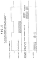
- FIG. 5 shows a relationship between the control bits CTL0 and CTL1, and the data island period and the control period.
- the control bits CTL0 and CTL1 may represent two states, i.e., a device enable state, and a device disable state.
- the device enable state is represented by an H (High) level
- the device disable state is represented by an L (Low) level.
- the control bits CTL0 and CTL1 are in the device disable state during the data island period, and are in the device enable state during the control period. Thus, the data island period and the control period are distinguished.
- the data which forms part of the auxiliary data and which is not related to control is transmitted, as shown in the second line from the top in FIG. 5 .
- the control period over which the control bits CTL0 and CTL1 are at the H level which is the device enable state data which forms part of the auxiliary data and which is related to control, such as the control packet, a preamble or the like, is transmitted, as shown in the third line from the top in FIG. 5 .
- the vertical synchronizing signal and the horizontal synchronizing signal also are transmitted, as shown in the fourth line from the top in FIG. 5 .
- HDMI transmitting unit (HDMI source) 143 of the wireless receiver 140 and the HDMI receiving unit (HDMI sink) 153 of the sink device 150 in the communication system 100 in FIG. 1 are also configured similarly to the HDMI transmitting unit 113 and the HDMI receiving unit 123.
- identification information identification information for identifying whether the image data is an image data of still picture content
- SPF Still Picture Flag inserted in the blanking period of the image data (the video signal) in the HDMI transmitting unit (HDMI source) 113 of the source device 110.
- FIG. 6 shows a data structure of an AVI (Auxiliary Video Information) InfoFrame packet located in the above-described data island period.
- AVI Advanced Video Information
- the AVI InfoFrame packet allows to transmit supplemental information regarding the video from the source device to the sink device.
- the AVI InfoFrame is transmitted once by each picture frame, so that data of the AVI InfoFrame is changed to inform the sink device of the change when a format or the like of the video signal is changed.
- the first to third bytes constitute a header.
- a packet type is written in the first byte.
- "0x82(8216)" which indicates the AVI InfoFrame packet used in the present invention is written.
- version information is written in the second byte.
- the third byte information which represents a packet length is written. In this case, "0xD(13)" is written.
- the identification information SPF is located at the eighth byte (Data Byte5) and the fourth bit of the AVI InfoFrame pacekt, as shown in the data structure in FIG. 6 .
- the reproducing unit 112 of the source device 110 the predetermined content is reproduced in response to a selection operation by a user.
- the baseband (uncompressed) video and audio data regarding the predetermined content, obtained in the reproducing unit 112, are supplied to the HDMI transmitting unit (HDMI source) 113.
- the identification information SPF indicating whether the content reproduced in the reproducing unit 112 is a still picture content is generated.
- the identification information SPF is supplied from the controller 111 to the HDMI transmitting unit (HDMI source) 113.
- the identification information SPF is inserted in the blanking period of the image data. That is, in the HDMI transmitting unit 113, the identification information SPF is located at the eighth byte (Data Byte5) and the fourth bit of the AVI InfoFrame packet inserted in the blanking period of the image data.
- the image data and the audio data in which the identification information SPF is inserted in the blanking period are transmitted unidirectionally via the HDMI cable 130 to the wireless transmitter 120.
- the HDMI receiving unit (HDMI sink) 123 of the wireless transmitter 120 according to a communication in compliance with the HDMI, the baseband video and audio data transmitted unidirectionally from the HDMI transmitting unit 113 of the source device 110 are received, and the received data are supplied to the wireless transmitting/receiving unit 124.
- the wireless transmitting/receiving unit 124 the baseband video and audio data supplied from the HDMI receiving unit (HDMI sink) 123 are upconverted to a signal of a predetermined frequency band, for example a 60-GHz (mille wave) band, and the upconverted signal is transmitted to the wireless transmission path 170.
- the wireless transmitting/receiving unit 142 of the wireless receiver 140 the signal upconverted to the predetermined frequency band as described above is received from the wireless transmission path 170, and the signal is subjected to a downconverting process. As a result, the baseband (uncompressed) video and audio data are obtained. Thus, the baseband video and audio data obtained in the wireless receiving unit 142 are supplied to the HDMI transmitting unit 143. In the HDMI transmitting unit 143, according to a communication in compliance with the HDMI, the baseband video and audio data supplied from the wireless transmitting/receiving unit 142 are transmitted unidirectionally via the HDMI cable 160 to the sink device 150.
- the baseband video and audio data transmitted unidirectionally from the HDMI transmitting unit (HDMI source) 143 of the wireless receiver 140 are received.
- the baseband (uncompressed) image data received in the HDMI receiving unit 153 is supplied to the display unit 154.
- the image data supplied from the HDMI receiving unit 153 is processed, and visual image produced by the image data is displayed.
- the baseband (uncompressed) audio data received in the HDMI receiving unit 153 is supplied to the speaker(not shown), and audible sound produced by the audio data is outputted.
- the identification information SPF inserted in the blanking period of the image data is acquired, and the identification information SPF is supplied to the controller 151.
- An operation in the display unit 154 is controlled based on the identification information SPF. That is, when the identification information SPF is "0", which is indicative of not a still picture content, the display unit 154 is controlled to receive the image data obtained in the HDMI receiving unit 153. In this case, the display unit 154 is in a refresh control state where a display is refreshed by each frame rate.
- the display unit 154 is controlled to stop receiving the image data obtained in the HDMI receiving unit 153. In this case, the display unit 154 is in a still control state where the image data held before stopping the reception is used to display.
- the source device 110 when the still picture content is reproduced in the reproducing unit 112, identical image data is repeatedly obtained by each frame rate from the reproducing unit 112, and as described above, the obtained data is upconverted to the predetermined frequency band by the wireless transmitter 120, and the upconverted data is transmitted to the wireless transmission path 170.
- the transmission of the image data regarding such a still picture content is performed only for a predetermined time period, and thereafter, the transmission is stopped.
- the sink device 150 stops receiving (refreshing) of the image data in a subsequent frame in which the identification information SPF in a state indicative of the still picture content is acquired, and a still picture display by the held image data is performed. Because of this, when the still picture content is reproduced in the reproducing unit 112, even if the transmission of the image data to the wireless transmission path 170 is stopped only for a predetermined time period, as above-described, a problem may not be found. Thus, the stop of the image data transmission allows the communication system to avoid a futile bandwidth occupation, whereby an effective utilization of a finite transmission bandwidth is enabled.
- the identification information SPF generated in the controller 111 is firstly in a state indicative of not a still picture content, and after a predetermined time period, the identification information SPF is changed to a state indicative of a still picture content.
- the sink device 150 stops receiving (refreshing) of the image data in a subsequent frame in which the identification information SPF in a state indicative of the still picture content is acquired, and a still picture display by the held image data is performed.
- the controller 151 of the sink device 150 recognizes that the identification information SPF remains in a state indicative of a still picture content, and the display unit 154 controlled by the controller 151 is caused to remain in a state where the reception of the image data is stopped.
- the image data of the other still picture content received by the HDMI receiving unit 153 is not received in the display unit 154.
- the display unit 154 of the sink device 150 receives the image data of the other still picture content, and thereafter, the reception of the image data is stopped again, and the display unit 154 is brought into a state where the held image data is used.
- FIG. 7 shows one example of a control sequence between the source device 110 and the sink device 150.
- the identification information SPF for identifying whether the predetermined content is a still picture content is inserted in the AVI InfoFrame packet located in the blanking period of the image data.
- the controller 151 is capable of identifying whether the transmitted image data is an image data of still picture content based on the identification information SPF.
- the display unit 154 stops receiving the image data under the control of the controller 151, and then, is moved to the still control state where the display is performed by using the held image data.
- the source device 110 is capable of stopping reproducing the still picture content transmitted from the reproducing unit 112 and stopping transmitting the image data of the still picture content to the sink device 150.
- the source device 110 is capable of stopping reproducing the still picture content transmitted from the reproducing unit 112 and stopping transmitting the image data of the still picture content to the sink device 150.
- FIG. 8 shows a configuration example of another communication system 200 to which the present invention is applied.
- the communication system 200 is configured by a source device 210 and a sink device 220.
- the source device 210 and the sink device 220 each have a wireless transmission function.
- the source device 210 includes a controller 211, a storage unit 212, a reproducing unit 213, and a wireless transmitting/receiving unit 214.
- the controller 211 controls operations of the reproducing unit 213 and the wireless transmitting/receiving unit 214.
- the storage unit 212 is connected to the controller 211.
- the storage unit 212 is stored with information or the like necessary for controlling the controller 211.
- the reproducing unit 213 reproduces baseband image data (an uncompressed video signal) and audio data (an audio signal) which accompanies the image data of a predetermined content such as a moving picture content, a still picture content, or the like, and supplies the reproduced data to the wireless transmitting/receiving unit 214. Selection of the reproduced contents in the reproducing unit 213 is controlled by the controller 211 in response to a user operation.
- the controller 211 generates the identification information for identifying whether the image data supplied from the reproducing unit 213 to the wireless transmitting/receiving unit 214 is an image data of still picture content, and supplies the identification information to the wireless transmitting/receiving unit 214.
- the wireless transmitting/receiving unit 214 upconverts the baseband video and audio data supplied from the reproducing unit 213 to a signal of a predetermined frequency band, for example a 60-GHz (mille wave) band, and transmits the upconverted signal to a wireless transmission path 230.
- the wireless transmitting/receiving unit 214 upconverts the identification information supplied from the controller 211 to the signal of the predetermined frequency band, and transmit the upconverted signal to the wireless transmission path 230. In this case, the identification information is transmitted to the wireless transmission path 230 asynchronously with the image data.
- the sink device 220 includes a controller 221, a storage unit 222, a wireless transmitting/receiving unit 223, and a display unit 224.
- the display unit 224 constitutes a video signal processor.
- the controller 221 controls operations of the wireless transmitting/receiving unit 223 and the display unit 224.
- the storage unit 222 is connected to the controller 221.
- the storage unit 222 is stored with information such as E-EDID (Enhanced-Extended Display Identification) or the like necessary for controlling the controller 221.
- the wireless transmitting/receiving unit 223 receives the signal upconverted to a predetermined frequency band from the wireless transmission path 230, and applies a downconverting process to the upconverted signal to obtain the above-described baseband video and audio data and the identification information (the identification information for identifying whether the image data is an image data of still picture content).
- the wireless transmitting/receiving unit 223 supplies the obtained baseband image data to the display unit 224.
- the wireless transmitting/receiving unit 223 supplies the obtained audio data to a speaker(not shown), for example. Audible sound produced by the received audio data is outputted from the speaker.
- the wireless transmitting/receiving unit 223 supplies the obtained identification information to the controller 221.
- the controller 221 controls a process operation to the image data in the display unit 224 based on the identification information.
- the display unit 224 is configured by a display element such as LCD (Liquid Crystal Display), organic EL (Electro Luminescence), CRT (Cathode Ray Tube) or the like, for example.
- the identification information (the identification information for identifying whether the image data is an image data of still picture content) generated in the controller 211 of the source device 210.
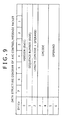
- an AVC Control/Message packet of which a data structure is shown in FIG. 9 for example, is used. That is, the controller 211 of the source device 210 generates the AVC Control/Message packet when the identification information is transmitted.
- the AVC Control/Message packet of the data structure shown in FIG. 9 also is used for a response from the sink device 220 to the source device 210.
- the Opcode is set to "0x0013" and the Operand is set to "0x0000" (accepted) or "0x0100" (not yet).
- a predetermined content is reproduced according to a selection operation of a user.
- Baseband (uncompressed) video and audio data related to the predetermined content, obtained in the reproducing unit 213, are supplied to the wireless transmitting/receiving unit 214.
- the wireless transmitting/receiving unit 214 the baseband video and audio data supplied from the reproducing unit 213 are upconverted to a signal of a predetermined frequency band, for example a 60-GHz (mille wave) band, and the upconverted signal is transmitted to the wireless transmission path 230.
- the above-described AVC Control/Message packet (see FIG. 9 ) including the identification information SPF indicating whether the predetermined content reproduced in the reproducing unit 213 is a still picture content is generated.
- the AVC Control/Message packet is supplied to the wireless transmitting/receiving unit 214.
- the wireless transmitting/receiving unit 214 the AVC Control/Message packet supplied from the controller 211 is upconverted to a signal of a predetermined frequency band, for example a 60-GHz (mille wave) band, and the upconverted signal is transmitted to the wireless transmission path 230.
- the signal thus upconverted to the predetermined frequency band is received from the wireless transmission path 230, and the received signal is subjected to a downconverting process.
- the above-described baseband (uncompressed) video and audio data and the AVC Control/Message packet including the identification information SPF are obtained.
- the baseband (uncompressed) image data obtained in the wireless transmitting/receiving unit 223 is supplied to the display unit 224.
- the image data supplied from the wireless transmitting/receiving unit 223 is processed, and visual image produced by the image data is displayed.
- the baseband (uncompressed) audio data obtained in the wireless transmitting/receiving unit 223 is supplied to a speaker (not shown), and audible sound produced by the audio data is outputted.
- the AVC Control/Message packet including the identification information SPF, which is obtained in the wireless transmitting/receiving unit 223, is supplied to the controller 221.
- An operation in the display unit 224 is controlled based on the identification information SPF. That is, when the identification information SPF, i.e., the Operand, is in a state indicative of not a still picture content (reset SPF), the display unit 224 is controlled to receive the image data obtained in the wireless transmitting/receiving unit 223. In this case, the display unit 224 is in a refresh control state where a display is refreshed by each frame rate.
- the display unit 224 When the identification information SPF, i.e., the Operand, is in a state indicative of a still picture content (set SPF), the display unit 224 is controlled to stop receiving the image data obtained in the wireless transmitting/receiving unit 223. In this case, the display unit 224 is in the still control state where the image data held before stopping the reception is used to display.
- the identification information SPF i.e., the Operand
- set SPF a state indicative of a still picture content
- the source device 210 when the still picture content is reproduced in the reproducing unit 213, identical image data are repeatedly obtained from the reproducing unit 213 by each frame rate, and as described above, the identical image data are transmitted from the wireless transmitting/receiving unit 214 to the wireless transmission path 230.
- the transmission of the image data regarding the still picture content like this is stopped later when there is a confirmation response (response) of the identification information SPF indicative of the still picture content from the sink device 220.
- the confirmation response is performed by using the AVC Control/Message packet, as described above.
- the sink device 220 stops receiving (refreshing) of the image data in a subsequent frame in which the identification information SPF in a state indicative of the still picture content is acquired, and a still picture display by the held image data is performed. Because of this, when the still picture content is reproduced in the reproducing unit 213, even if the transmission of the image data to the wireless transmission path 230 is stopped after there is the confirmation response (response) of the identification information SPF, a problem may not be found. When the transmission of the image data is stopped in this way, a futile bandwidth occupation is avoided, and an effective utilization of a finite transmission bandwidth is enabled.
- the identification information SPF generated in the controller 211 is set to a state (reset SPF) indicative of not a still picture content, and after a predetermined time period, this state is changed to a state (set SPF) indicative of a still picture content.
- the sink device 220 stops receiving (refreshing) of the image data in a subsequent frame in which the identification information SPF in a state indicative of the still picture content is acquired, and a still picture display by the held image data is performed.
- the controller 221 of the sink device 220 recognizes that the identification information SPF remains in a state indicative of a still picture content, and the display unit 224 controlled by the controller 221 is caused to remain in a state where the reception of the image data is stopped.
- the image data of the other still picture content received by the wireless transmitting/receiving unit 223 is not received in the display unit 224.
- the display unit 224 of the sink device 220 receives the image data of the other still picture content, and thereafter, the reception of the image data is stopped again. As a result, the display unit 224 is brought into a state where the held image data is used.
- FIG. 10 shows one example of a control sequence between the source device 210 and the sink device 220.
- the AVC Control/Message packet including the identification information SPF in a state (set SPF) indicative of a still picture content is transmitted in response to the transmitting of the image data from the source device 210 to the sink device 220.
- the controller 221 identifies whether the transmitted image data is an image data of a still picture content based on the identification information SPF.
- the display unit 224 stops receiving the image data under the control of the controller 221, and then, the display unit 224 is moved to the still control state where the display is performed by using the held image data.
- the source device 210 stops reproducing the still picture content from the reproducing unit 213 and stops transmitting the image data of the still picture content to the sink device 220.
- the source device 210 stops reproducing the still picture content from the reproducing unit 213 and stops transmitting the image data of the still picture content to the sink device 220.
- the above-described embodiment shows a case where the video signal processor of the receiver is the display unit 154 or 224 (see FIG. 1 and FIG. 8 ).
- the present invention may be similarly applicable to a case where the video signal processor of the receiver is a unit for performing another process such as a recording unit where a received video signal is recorded.
- the above-described embodiment shows a case where the identification information SPF indicating whether the baseband (uncompressed) video signal (image data) transmitted from the transmitter to the receiver is a still picture content is transmitted by utilizing the AVI InfoFrame packet located in the blanking period of the video signal, or by utilizing the AVC Control/Message packet.
- means for transmitting the identification information SPF is not limited thereto.
- identification information for identifying whether the predetermined content is a still picture content is further transmitted, so that a futile bandwidth occupation may be avoided and a finite transmission bandwidth may be effectively utilized.
- Embodiments of the present invention are capable of avoiding a futile bandwidth occupation and effectively utilizing a finite transmission bandwidth, and are applicable to a communication system in which a baseband (uncompressed) video signal of content is wirelessly transmitted from a transmitter to a receiver.
Landscapes
- Engineering & Computer Science (AREA)
- Signal Processing (AREA)
- Multimedia (AREA)
- Computer Networks & Wireless Communication (AREA)
- Databases & Information Systems (AREA)
- General Physics & Mathematics (AREA)
- Astronomy & Astrophysics (AREA)
- Physics & Mathematics (AREA)
- Computer Graphics (AREA)
- Two-Way Televisions, Distribution Of Moving Picture Or The Like (AREA)
- Radar Systems Or Details Thereof (AREA)
- Reduction Or Emphasis Of Bandwidth Of Signals (AREA)
- Circuits Of Receivers In General (AREA)
- Mobile Radio Communication Systems (AREA)
- Television Systems (AREA)
Applications Claiming Priority (1)
| Application Number | Priority Date | Filing Date | Title |
|---|---|---|---|
| JP2007127159A JP2008283561A (ja) | 2007-05-11 | 2007-05-11 | 通信システム、映像信号伝送方法、送信装置、送信方法、受信装置および受信方法 |
Publications (3)
| Publication Number | Publication Date |
|---|---|
| EP1990992A2 true EP1990992A2 (de) | 2008-11-12 |
| EP1990992A3 EP1990992A3 (de) | 2011-01-05 |
| EP1990992B1 EP1990992B1 (de) | 2012-03-14 |
Family
ID=39535170
Family Applications (1)
| Application Number | Title | Priority Date | Filing Date |
|---|---|---|---|
| EP08155954A Not-in-force EP1990992B1 (de) | 2007-05-11 | 2008-05-09 | Kommunikationssystem, Videosignal, Übertragungsverfahren, Sender, Sendeverfahren, Empfänger und Empfangsverfahren |
Country Status (11)
| Country | Link |
|---|---|
| US (1) | US8856840B2 (de) |
| EP (1) | EP1990992B1 (de) |
| JP (1) | JP2008283561A (de) |
| KR (1) | KR20080100125A (de) |
| CN (1) | CN101304510B (de) |
| AT (1) | ATE549858T1 (de) |
| BR (1) | BRPI0801370A2 (de) |
| ES (1) | ES2384354T3 (de) |
| IL (1) | IL190981A (de) |
| RU (1) | RU2389140C2 (de) |
| TW (1) | TW200910947A (de) |
Cited By (3)
| Publication number | Priority date | Publication date | Assignee | Title |
|---|---|---|---|---|
| EP2785052A4 (de) * | 2011-11-25 | 2015-03-11 | Panasonic Corp | Übertragungsvorrichtung und empfangsvorrichtung für basisbandvideodaten sowie sender-empfängersystem |
| WO2016148935A1 (en) * | 2015-03-13 | 2016-09-22 | Dolby Laboratories Licensing Corporation | Media stick for controlling wireless speakers |
| CN109905751A (zh) * | 2019-03-01 | 2019-06-18 | 四川长虹电器股份有限公司 | 一种智能画框的控制方法及系统 |
Families Citing this family (43)
| Publication number | Priority date | Publication date | Assignee | Title |
|---|---|---|---|---|
| US11769398B2 (en) | 2005-09-08 | 2023-09-26 | Universal Electronics Inc. | System and method for widget-assisted setup of a universal remote control |
| US7907222B2 (en) | 2005-09-08 | 2011-03-15 | Universal Electronics Inc. | System and method for simplified setup of a universal remote control |
| US9208679B2 (en) * | 2006-09-05 | 2015-12-08 | Universal Electronics Inc. | System and method for configuring the remote control functionality of a portable device |
| US9088663B2 (en) | 2008-04-18 | 2015-07-21 | Universal Electronics Inc. | System for appliance control via a network |
| US9852615B2 (en) | 2011-03-25 | 2017-12-26 | Universal Electronics Inc. | System and method for facilitating appliance control via a smart device |
| JP5262546B2 (ja) * | 2008-10-08 | 2013-08-14 | ソニー株式会社 | 映像信号処理システム、再生装置および表示装置、ならびに映像信号処理方法 |
| US8429440B2 (en) | 2009-05-13 | 2013-04-23 | Stmicroelectronics, Inc. | Flat panel display driver method and system |
| US8156238B2 (en) * | 2009-05-13 | 2012-04-10 | Stmicroelectronics, Inc. | Wireless multimedia transport method and apparatus |
| JP4592806B1 (ja) * | 2009-06-18 | 2010-12-08 | 株式会社東芝 | 無線通信装置 |
| JP4564574B1 (ja) | 2009-06-24 | 2010-10-20 | 株式会社東芝 | 通信装置 |
| US8345681B2 (en) * | 2009-09-23 | 2013-01-01 | Samsung Electronics Co., Ltd. | Method and system for wireless communication of audio in wireless networks |
| JP2015039051A (ja) * | 2009-12-21 | 2015-02-26 | 株式会社東芝 | 情報送信装置、情報受信装置および情報伝送方法 |
| US8671234B2 (en) | 2010-05-27 | 2014-03-11 | Stmicroelectronics, Inc. | Level shifting cable adaptor and chip system for use with dual-mode multi-media device |
| JP5571465B2 (ja) * | 2010-06-08 | 2014-08-13 | シャープ株式会社 | コンテンツ再生システム |
| US8803940B2 (en) * | 2010-07-28 | 2014-08-12 | Verizon Patent And Licensing Inc. | Merging content |
| US10135900B2 (en) | 2011-01-21 | 2018-11-20 | Qualcomm Incorporated | User input back channel for wireless displays |
| US9787725B2 (en) * | 2011-01-21 | 2017-10-10 | Qualcomm Incorporated | User input back channel for wireless displays |
| US8812601B2 (en) | 2011-05-09 | 2014-08-19 | Google Inc. | Transferring application state across devices with checkpoints |
| US8224894B1 (en) | 2011-05-09 | 2012-07-17 | Google Inc. | Zero-click sharing of application context across devices |
| US8171137B1 (en) | 2011-05-09 | 2012-05-01 | Google Inc. | Transferring application state across devices |
| JP5762854B2 (ja) * | 2011-06-30 | 2015-08-12 | Dxアンテナ株式会社 | 通信システム |
| US9019435B2 (en) | 2011-09-22 | 2015-04-28 | Universal Electronics Inc. | System and method for configuring controlling device functionality |
| US11756412B2 (en) | 2011-10-28 | 2023-09-12 | Universal Electronics Inc. | Systems and methods for associating services and/or devices with a voice assistant |
| US9215394B2 (en) | 2011-10-28 | 2015-12-15 | Universal Electronics Inc. | System and method for optimized appliance control |
| US10593195B2 (en) | 2011-10-28 | 2020-03-17 | Universal Electronics Inc. | System and method for optimized appliance control |
| US9449500B2 (en) * | 2012-08-08 | 2016-09-20 | Universal Electronics Inc. | System and method for optimized appliance control |
| US10937308B2 (en) | 2011-10-28 | 2021-03-02 | Universal Electronics Inc. | System and method for optimized appliance control |
| US11295603B2 (en) | 2011-10-28 | 2022-04-05 | Universal Electronics Inc. | System and method for optimized appliance control |
| KR20130128266A (ko) * | 2012-05-16 | 2013-11-26 | 삼성전자주식회사 | 컨텐츠 수신 장치, 디스플레이 장치 및 그 방법 |
| US9184800B2 (en) | 2012-07-16 | 2015-11-10 | Google Inc. | Automated sharing of application data over a near field communication link |
| EP2894861B1 (de) | 2012-09-07 | 2020-01-01 | Saturn Licensing LLC | Sendevorrichtung, sendeverfahren, empfangsvorrichtung und empfangsverfahren |
| US9351128B2 (en) * | 2013-01-04 | 2016-05-24 | Qualcomm Incorporated | Selectively adjusting a rate or delivery format of media being delivered to one or more multicast/broadcast single frequency networks for transmission |
| US9526120B2 (en) | 2013-03-15 | 2016-12-20 | Google Inc. | Techniques for context-based application invocation for short-range wireless communication interactions |
| JP2014200076A (ja) * | 2013-03-15 | 2014-10-23 | 株式会社リコー | 配信制御システム、配信制御方法、及びプログラム |
| JP6607298B2 (ja) * | 2013-03-15 | 2019-11-20 | 株式会社リコー | 配信制御システム、配信制御方法、及びプログラム |
| CN103731646A (zh) * | 2014-01-23 | 2014-04-16 | 中国科学院电子学研究所 | 一种视频信号实时截取处理显示方法和装置 |
| US20150256842A1 (en) * | 2014-03-07 | 2015-09-10 | Silicon Image, Inc. | Compressed Video Transfer over a Multimedia Link |
| CN107408331B (zh) * | 2014-04-04 | 2021-06-18 | 通用电子有限公司 | 用于配置便携式设备的遥控功能的系统和方法 |
| KR102495076B1 (ko) * | 2015-02-04 | 2023-02-02 | 유니버샬 일렉트로닉스 인코포레이티드 | 휴대용 장치의 리모트 컨트롤 기능을 설정하는 시스템 및 방법 |
| KR101702373B1 (ko) * | 2015-03-20 | 2017-02-03 | 주식회사 와이젯 | 고속 무선전송 기능을 갖는 무선인터페이스를 포함하는 hmd 장치 |
| US11818490B2 (en) | 2018-12-20 | 2023-11-14 | Lg Electronics Inc. | Video transmitting device and video receiving device |
| US11620251B2 (en) * | 2021-05-24 | 2023-04-04 | Cadence Design Systems, Inc. | Partitioned UFP for displayport repeater |
| US11412177B1 (en) * | 2021-07-12 | 2022-08-09 | Techpoint, Inc. | Method and apparatus for transmitting and receiving audio over analog video transmission over a single coaxial cable |
Citations (3)
| Publication number | Priority date | Publication date | Assignee | Title |
|---|---|---|---|---|
| JP2005142709A (ja) | 2003-11-05 | 2005-06-02 | Matsushita Electric Ind Co Ltd | 画像表示システム |
| US20060209745A1 (en) | 2005-03-15 | 2006-09-21 | Radiospire Networks, Inc. | System, method and apparatus for wireless delivery of content from a generalized content source to a generalized content sink |
| JP2006319503A (ja) | 2005-05-11 | 2006-11-24 | Sony Corp | 映像信号処理装置および方法、並びにプログラム |
Family Cites Families (23)
| Publication number | Priority date | Publication date | Assignee | Title |
|---|---|---|---|---|
| US5122875A (en) * | 1991-02-27 | 1992-06-16 | General Electric Company | An HDTV compression system |
| NZ500194A (en) * | 1997-03-21 | 2000-12-22 | Canal Plus Sa | Broadcasting randomized subscriber entitlement management messages for digital television |
| EP0939517A4 (de) * | 1997-08-04 | 2006-01-04 | Matsushita Electric Industrial Co Ltd | Netzsteuersystem |
| US6570606B1 (en) * | 1998-05-29 | 2003-05-27 | 3Com Corporation | Method and apparatus for controlling transmission of media signals over a data network in response to triggering events at participating stations |
| WO2001052535A2 (en) * | 2000-01-14 | 2001-07-19 | Koninklijke Philips Electronics N.V. | Transmission system, transmitter and receiver |
| JP4040826B2 (ja) * | 2000-06-23 | 2008-01-30 | 株式会社東芝 | 画像処理方法および画像表示システム |
| JP3573724B2 (ja) * | 2000-07-21 | 2004-10-06 | 松下電器産業株式会社 | 伝送システム、送信装置、受信装置、および伝送方法、送信方法、受信方法 |
| US20020099800A1 (en) * | 2000-11-27 | 2002-07-25 | Robert Brainard | Data mark and recall system and method for a data stream |
| JP3788260B2 (ja) * | 2001-04-09 | 2006-06-21 | 日本電気株式会社 | 配信システムとその配信方法、及び配信プログラム |
| JP3620521B2 (ja) * | 2001-09-14 | 2005-02-16 | 日本電気株式会社 | 画像処理装置、画像伝送装置、画像受信装置及び画像処理方法 |
| JP4516280B2 (ja) * | 2003-03-10 | 2010-08-04 | ルネサスエレクトロニクス株式会社 | 表示装置の駆動回路 |
| US8995536B2 (en) * | 2003-07-23 | 2015-03-31 | Broadcom Corporation | System and method for audio/video synchronization |
| JP2005151150A (ja) | 2003-11-14 | 2005-06-09 | Marantz Japan Inc | 画像伝送システム |
| JP4347724B2 (ja) * | 2004-03-05 | 2009-10-21 | 富士フイルム株式会社 | 画像ファイル生成装置および方法ならびに画像ファイル再生装置および方法 |
| US8042145B2 (en) * | 2005-08-23 | 2011-10-18 | Koninklijke Philips Electronics N.V. | Method of controlling power states in a multimedia system |
| JP2007240741A (ja) * | 2006-03-07 | 2007-09-20 | Canon Inc | 画像制御装置及び画像制御方法 |
| US8363675B2 (en) * | 2006-03-24 | 2013-01-29 | Samsung Electronics Co., Ltd. | Method and system for transmission of uncompressed video over wireless communication channels |
| US8432938B2 (en) * | 2006-03-29 | 2013-04-30 | Samsung Electronics Co., Ltd. | Method and system for video stream transmission over wireless channels |
| US20100303158A1 (en) * | 2006-06-08 | 2010-12-02 | Thomson Licensing | Method and apparatus for scene change detection |
| US20070288980A1 (en) * | 2006-06-08 | 2007-12-13 | Huaning Niu | System and method for digital communication having a frame format and parsing scheme with parallel convolutional encoders |
| US8826348B2 (en) * | 2006-12-04 | 2014-09-02 | Samsung Electronics Co., Ltd. | System and method for wireless communication of uncompressed video having a relay device for power saving |
| US20080168519A1 (en) * | 2007-01-05 | 2008-07-10 | Radiospire Networks, Inc. | System, method and apparatus for connecting multiple audio/video sources to an audio/video sink |
| JP4829806B2 (ja) * | 2007-01-30 | 2011-12-07 | キヤノン株式会社 | データ処理装置及びコンピュータプログラム |
-
2007
- 2007-05-11 JP JP2007127159A patent/JP2008283561A/ja active Pending
-
2008
- 2008-04-17 IL IL190981A patent/IL190981A/en not_active IP Right Cessation
- 2008-04-28 KR KR1020080039247A patent/KR20080100125A/ko not_active Ceased
- 2008-04-29 US US12/150,493 patent/US8856840B2/en not_active Expired - Fee Related
- 2008-05-02 TW TW097116316A patent/TW200910947A/zh unknown
- 2008-05-07 RU RU2008118280/09A patent/RU2389140C2/ru not_active IP Right Cessation
- 2008-05-07 BR BRPI0801370-5A patent/BRPI0801370A2/pt not_active IP Right Cessation
- 2008-05-09 AT AT08155954T patent/ATE549858T1/de active
- 2008-05-09 EP EP08155954A patent/EP1990992B1/de not_active Not-in-force
- 2008-05-09 ES ES08155954T patent/ES2384354T3/es active Active
- 2008-05-12 CN CN2008100970479A patent/CN101304510B/zh not_active Expired - Fee Related
Patent Citations (3)
| Publication number | Priority date | Publication date | Assignee | Title |
|---|---|---|---|---|
| JP2005142709A (ja) | 2003-11-05 | 2005-06-02 | Matsushita Electric Ind Co Ltd | 画像表示システム |
| US20060209745A1 (en) | 2005-03-15 | 2006-09-21 | Radiospire Networks, Inc. | System, method and apparatus for wireless delivery of content from a generalized content source to a generalized content sink |
| JP2006319503A (ja) | 2005-05-11 | 2006-11-24 | Sony Corp | 映像信号処理装置および方法、並びにプログラム |
Cited By (5)
| Publication number | Priority date | Publication date | Assignee | Title |
|---|---|---|---|---|
| EP2785052A4 (de) * | 2011-11-25 | 2015-03-11 | Panasonic Corp | Übertragungsvorrichtung und empfangsvorrichtung für basisbandvideodaten sowie sender-empfängersystem |
| WO2016148935A1 (en) * | 2015-03-13 | 2016-09-22 | Dolby Laboratories Licensing Corporation | Media stick for controlling wireless speakers |
| US10491851B2 (en) | 2015-03-13 | 2019-11-26 | Dolby Laboratories Licensing Corporation | Media stick for controlling wireless speakers |
| CN109905751A (zh) * | 2019-03-01 | 2019-06-18 | 四川长虹电器股份有限公司 | 一种智能画框的控制方法及系统 |
| CN109905751B (zh) * | 2019-03-01 | 2020-12-15 | 四川长虹电器股份有限公司 | 一种智能画框的控制方法及系统 |
Also Published As
| Publication number | Publication date |
|---|---|
| CN101304510B (zh) | 2010-12-01 |
| EP1990992B1 (de) | 2012-03-14 |
| JP2008283561A (ja) | 2008-11-20 |
| RU2008118280A (ru) | 2009-11-20 |
| ES2384354T3 (es) | 2012-07-04 |
| IL190981A0 (en) | 2009-02-11 |
| US8856840B2 (en) | 2014-10-07 |
| TW200910947A (en) | 2009-03-01 |
| ATE549858T1 (de) | 2012-03-15 |
| RU2389140C2 (ru) | 2010-05-10 |
| IL190981A (en) | 2013-11-28 |
| US20080278567A1 (en) | 2008-11-13 |
| KR20080100125A (ko) | 2008-11-14 |
| BRPI0801370A2 (pt) | 2009-01-06 |
| EP1990992A3 (de) | 2011-01-05 |
| CN101304510A (zh) | 2008-11-12 |
Similar Documents
| Publication | Publication Date | Title |
|---|---|---|
| EP1990992B1 (de) | Kommunikationssystem, Videosignal, Übertragungsverfahren, Sender, Sendeverfahren, Empfänger und Empfangsverfahren | |
| US9807363B2 (en) | Transmitting apparatus, stereo image data transmitting method, receiving apparatus, and stereo image data receiving method | |
| CN101573975B (zh) | 接收器、用于接收器的延迟信息发送方法、音频输出装置、及用于音频输出装置的延迟控制方法 | |
| EP2091253B1 (de) | Sendeeinrichtung, videosignalsendeverfahren in einer sendeeinrichtung, empfangseinrichtung und videosignalempfangsverfahren in einer empfangseinrichtung | |
| EP2071849A1 (de) | Empfänger, verfahren zur verzögerten informationssendung für empfänger, audioausgabevorrichtung und verzögerungssteuerungsverfahren für audioausgabegeräte | |
| EP2312849A1 (de) | Verfahren, Systeme und Vorrichtungen zur Verdichtung von Daten und Übertragung dieser unter Verwendung von Übertragungsstandards | |
| EP2388688B1 (de) | Datenübertragungsvorrichtung, Datenempfangsvorrichtung, Datenübertragungsverfahren und Datenempfangsverfahren um Untertitel-Pakete unter Verwendung von HDMI zu übertragen/empfangen | |
| US20130100247A1 (en) | Image data transmission apparatus, control method for image data transmission apparatus, image data transmission method, and image data reception apparatus | |
| WO2015079655A1 (en) | Transmission apparatus, method of transmitting image data with wide color gamut, reception apparatus, method of receiving image data with wide color gamut, and program | |
| EP2413611B1 (de) | Bilddatenübertragungsvorrichtung, bilddatenübertragungsverfahren und bilddatenempfangsvorrichtung |
Legal Events
| Date | Code | Title | Description |
|---|---|---|---|
| PUAI | Public reference made under article 153(3) epc to a published international application that has entered the european phase |
Free format text: ORIGINAL CODE: 0009012 |
|
| AK | Designated contracting states |
Kind code of ref document: A2 Designated state(s): AT BE BG CH CY CZ DE DK EE ES FI FR GB GR HR HU IE IS IT LI LT LU LV MC MT NL NO PL PT RO SE SI SK TR |
|
| AX | Request for extension of the european patent |
Extension state: AL BA MK RS |
|
| 17P | Request for examination filed |
Effective date: 20090511 |
|
| PUAL | Search report despatched |
Free format text: ORIGINAL CODE: 0009013 |
|
| AK | Designated contracting states |
Kind code of ref document: A3 Designated state(s): AT BE BG CH CY CZ DE DK EE ES FI FR GB GR HR HU IE IS IT LI LT LU LV MC MT NL NO PL PT RO SE SI SK TR |
|
| AX | Request for extension of the european patent |
Extension state: AL BA MK RS |
|
| RIC1 | Information provided on ipc code assigned before grant |
Ipc: H04N 5/44 20110101AFI20110728BHEP |
|
| AKX | Designation fees paid |
Designated state(s): AT BE BG CH CY CZ DE DK EE ES FI FR GB GR HR HU IE IS IT LI LT LU LV MC MT NL NO PL PT RO SE SI SK TR |
|
| GRAP | Despatch of communication of intention to grant a patent |
Free format text: ORIGINAL CODE: EPIDOSNIGR1 |
|
| GRAS | Grant fee paid |
Free format text: ORIGINAL CODE: EPIDOSNIGR3 |
|
| GRAA | (expected) grant |
Free format text: ORIGINAL CODE: 0009210 |
|
| AK | Designated contracting states |
Kind code of ref document: B1 Designated state(s): AT BE BG CH CY CZ DE DK EE ES FI FR GB GR HR HU IE IS IT LI LT LU LV MC MT NL NO PL PT RO SE SI SK TR |
|
| REG | Reference to a national code |
Ref country code: GB Ref legal event code: FG4D |
|
| REG | Reference to a national code |
Ref country code: AT Ref legal event code: REF Ref document number: 549858 Country of ref document: AT Kind code of ref document: T Effective date: 20120315 Ref country code: CH Ref legal event code: EP |
|
| REG | Reference to a national code |
Ref country code: IE Ref legal event code: FG4D |
|
| REG | Reference to a national code |
Ref country code: DE Ref legal event code: R096 Ref document number: 602008014064 Country of ref document: DE Effective date: 20120510 |
|
| REG | Reference to a national code |
Ref country code: NL Ref legal event code: T3 |
|
| REG | Reference to a national code |
Ref country code: ES Ref legal event code: FG2A Ref document number: 2384354 Country of ref document: ES Kind code of ref document: T3 Effective date: 20120704 |
|
| PG25 | Lapsed in a contracting state [announced via postgrant information from national office to epo] |
Ref country code: NO Free format text: LAPSE BECAUSE OF FAILURE TO SUBMIT A TRANSLATION OF THE DESCRIPTION OR TO PAY THE FEE WITHIN THE PRESCRIBED TIME-LIMIT Effective date: 20120614 Ref country code: LT Free format text: LAPSE BECAUSE OF FAILURE TO SUBMIT A TRANSLATION OF THE DESCRIPTION OR TO PAY THE FEE WITHIN THE PRESCRIBED TIME-LIMIT Effective date: 20120314 Ref country code: HR Free format text: LAPSE BECAUSE OF FAILURE TO SUBMIT A TRANSLATION OF THE DESCRIPTION OR TO PAY THE FEE WITHIN THE PRESCRIBED TIME-LIMIT Effective date: 20120314 |
|
| LTIE | Lt: invalidation of european patent or patent extension |
Effective date: 20120314 |
|
| PG25 | Lapsed in a contracting state [announced via postgrant information from national office to epo] |
Ref country code: FI Free format text: LAPSE BECAUSE OF FAILURE TO SUBMIT A TRANSLATION OF THE DESCRIPTION OR TO PAY THE FEE WITHIN THE PRESCRIBED TIME-LIMIT Effective date: 20120314 Ref country code: LV Free format text: LAPSE BECAUSE OF FAILURE TO SUBMIT A TRANSLATION OF THE DESCRIPTION OR TO PAY THE FEE WITHIN THE PRESCRIBED TIME-LIMIT Effective date: 20120314 Ref country code: GR Free format text: LAPSE BECAUSE OF FAILURE TO SUBMIT A TRANSLATION OF THE DESCRIPTION OR TO PAY THE FEE WITHIN THE PRESCRIBED TIME-LIMIT Effective date: 20120615 |
|
| PG25 | Lapsed in a contracting state [announced via postgrant information from national office to epo] |
Ref country code: CY Free format text: LAPSE BECAUSE OF FAILURE TO SUBMIT A TRANSLATION OF THE DESCRIPTION OR TO PAY THE FEE WITHIN THE PRESCRIBED TIME-LIMIT Effective date: 20120314 |
|
| PG25 | Lapsed in a contracting state [announced via postgrant information from national office to epo] |
Ref country code: RO Free format text: LAPSE BECAUSE OF FAILURE TO SUBMIT A TRANSLATION OF THE DESCRIPTION OR TO PAY THE FEE WITHIN THE PRESCRIBED TIME-LIMIT Effective date: 20120314 Ref country code: SE Free format text: LAPSE BECAUSE OF FAILURE TO SUBMIT A TRANSLATION OF THE DESCRIPTION OR TO PAY THE FEE WITHIN THE PRESCRIBED TIME-LIMIT Effective date: 20120314 Ref country code: IS Free format text: LAPSE BECAUSE OF FAILURE TO SUBMIT A TRANSLATION OF THE DESCRIPTION OR TO PAY THE FEE WITHIN THE PRESCRIBED TIME-LIMIT Effective date: 20120714 Ref country code: EE Free format text: LAPSE BECAUSE OF FAILURE TO SUBMIT A TRANSLATION OF THE DESCRIPTION OR TO PAY THE FEE WITHIN THE PRESCRIBED TIME-LIMIT Effective date: 20120314 Ref country code: PL Free format text: LAPSE BECAUSE OF FAILURE TO SUBMIT A TRANSLATION OF THE DESCRIPTION OR TO PAY THE FEE WITHIN THE PRESCRIBED TIME-LIMIT Effective date: 20120314 Ref country code: BE Free format text: LAPSE BECAUSE OF FAILURE TO SUBMIT A TRANSLATION OF THE DESCRIPTION OR TO PAY THE FEE WITHIN THE PRESCRIBED TIME-LIMIT Effective date: 20120314 Ref country code: CZ Free format text: LAPSE BECAUSE OF FAILURE TO SUBMIT A TRANSLATION OF THE DESCRIPTION OR TO PAY THE FEE WITHIN THE PRESCRIBED TIME-LIMIT Effective date: 20120314 Ref country code: SI Free format text: LAPSE BECAUSE OF FAILURE TO SUBMIT A TRANSLATION OF THE DESCRIPTION OR TO PAY THE FEE WITHIN THE PRESCRIBED TIME-LIMIT Effective date: 20120314 |
|
| PG25 | Lapsed in a contracting state [announced via postgrant information from national office to epo] |
Ref country code: PT Free format text: LAPSE BECAUSE OF FAILURE TO SUBMIT A TRANSLATION OF THE DESCRIPTION OR TO PAY THE FEE WITHIN THE PRESCRIBED TIME-LIMIT Effective date: 20120716 Ref country code: SK Free format text: LAPSE BECAUSE OF FAILURE TO SUBMIT A TRANSLATION OF THE DESCRIPTION OR TO PAY THE FEE WITHIN THE PRESCRIBED TIME-LIMIT Effective date: 20120314 |
|
| PG25 | Lapsed in a contracting state [announced via postgrant information from national office to epo] |
Ref country code: MC Free format text: LAPSE BECAUSE OF NON-PAYMENT OF DUE FEES Effective date: 20120531 |
|
| REG | Reference to a national code |
Ref country code: CH Ref legal event code: PL |
|
| PLBE | No opposition filed within time limit |
Free format text: ORIGINAL CODE: 0009261 |
|
| STAA | Information on the status of an ep patent application or granted ep patent |
Free format text: STATUS: NO OPPOSITION FILED WITHIN TIME LIMIT |
|
| PG25 | Lapsed in a contracting state [announced via postgrant information from national office to epo] |
Ref country code: LI Free format text: LAPSE BECAUSE OF NON-PAYMENT OF DUE FEES Effective date: 20120531 Ref country code: CH Free format text: LAPSE BECAUSE OF NON-PAYMENT OF DUE FEES Effective date: 20120531 Ref country code: DK Free format text: LAPSE BECAUSE OF FAILURE TO SUBMIT A TRANSLATION OF THE DESCRIPTION OR TO PAY THE FEE WITHIN THE PRESCRIBED TIME-LIMIT Effective date: 20120314 |
|
| 26N | No opposition filed |
Effective date: 20121217 |
|
| REG | Reference to a national code |
Ref country code: IE Ref legal event code: MM4A |
|
| REG | Reference to a national code |
Ref country code: DE Ref legal event code: R097 Ref document number: 602008014064 Country of ref document: DE Effective date: 20121217 |
|
| PG25 | Lapsed in a contracting state [announced via postgrant information from national office to epo] |
Ref country code: IE Free format text: LAPSE BECAUSE OF NON-PAYMENT OF DUE FEES Effective date: 20120509 |
|
| PG25 | Lapsed in a contracting state [announced via postgrant information from national office to epo] |
Ref country code: BG Free format text: LAPSE BECAUSE OF FAILURE TO SUBMIT A TRANSLATION OF THE DESCRIPTION OR TO PAY THE FEE WITHIN THE PRESCRIBED TIME-LIMIT Effective date: 20120614 Ref country code: MT Free format text: LAPSE BECAUSE OF FAILURE TO SUBMIT A TRANSLATION OF THE DESCRIPTION OR TO PAY THE FEE WITHIN THE PRESCRIBED TIME-LIMIT Effective date: 20120314 |
|
| PG25 | Lapsed in a contracting state [announced via postgrant information from national office to epo] |
Ref country code: TR Free format text: LAPSE BECAUSE OF FAILURE TO SUBMIT A TRANSLATION OF THE DESCRIPTION OR TO PAY THE FEE WITHIN THE PRESCRIBED TIME-LIMIT Effective date: 20120314 |
|
| PG25 | Lapsed in a contracting state [announced via postgrant information from national office to epo] |
Ref country code: LU Free format text: LAPSE BECAUSE OF NON-PAYMENT OF DUE FEES Effective date: 20120509 |
|
| REG | Reference to a national code |
Ref country code: AT Ref legal event code: MM01 Ref document number: 549858 Country of ref document: AT Kind code of ref document: T Effective date: 20130509 |
|
| PG25 | Lapsed in a contracting state [announced via postgrant information from national office to epo] |
Ref country code: HU Free format text: LAPSE BECAUSE OF FAILURE TO SUBMIT A TRANSLATION OF THE DESCRIPTION OR TO PAY THE FEE WITHIN THE PRESCRIBED TIME-LIMIT Effective date: 20080509 |
|
| PG25 | Lapsed in a contracting state [announced via postgrant information from national office to epo] |
Ref country code: AT Free format text: LAPSE BECAUSE OF NON-PAYMENT OF DUE FEES Effective date: 20130509 |
|
| PGFP | Annual fee paid to national office [announced via postgrant information from national office to epo] |
Ref country code: ES Payment date: 20140528 Year of fee payment: 7 Ref country code: IT Payment date: 20140523 Year of fee payment: 7 Ref country code: NL Payment date: 20140521 Year of fee payment: 7 |
|
| REG | Reference to a national code |
Ref country code: DE Ref legal event code: R084 Ref document number: 602008014064 Country of ref document: DE |
|
| REG | Reference to a national code |
Ref country code: GB Ref legal event code: 746 Effective date: 20150421 |
|
| REG | Reference to a national code |
Ref country code: DE Ref legal event code: R084 Ref document number: 602008014064 Country of ref document: DE Effective date: 20150410 |
|
| PG25 | Lapsed in a contracting state [announced via postgrant information from national office to epo] |
Ref country code: IT Free format text: LAPSE BECAUSE OF NON-PAYMENT OF DUE FEES Effective date: 20150509 |
|
| REG | Reference to a national code |
Ref country code: NL Ref legal event code: MM Effective date: 20150601 |
|
| PG25 | Lapsed in a contracting state [announced via postgrant information from national office to epo] |
Ref country code: NL Free format text: LAPSE BECAUSE OF NON-PAYMENT OF DUE FEES Effective date: 20150601 |
|
| REG | Reference to a national code |
Ref country code: FR Ref legal event code: PLFP Year of fee payment: 9 |
|
| REG | Reference to a national code |
Ref country code: ES Ref legal event code: FD2A Effective date: 20160628 |
|
| PG25 | Lapsed in a contracting state [announced via postgrant information from national office to epo] |
Ref country code: ES Free format text: LAPSE BECAUSE OF NON-PAYMENT OF DUE FEES Effective date: 20150510 |
|
| REG | Reference to a national code |
Ref country code: FR Ref legal event code: PLFP Year of fee payment: 10 |
|
| REG | Reference to a national code |
Ref country code: FR Ref legal event code: PLFP Year of fee payment: 11 |
|
| PGFP | Annual fee paid to national office [announced via postgrant information from national office to epo] |
Ref country code: FR Payment date: 20190523 Year of fee payment: 12 |
|
| PGFP | Annual fee paid to national office [announced via postgrant information from national office to epo] |
Ref country code: GB Payment date: 20190521 Year of fee payment: 12 |
|
| GBPC | Gb: european patent ceased through non-payment of renewal fee |
Effective date: 20200509 |
|
| PG25 | Lapsed in a contracting state [announced via postgrant information from national office to epo] |
Ref country code: FR Free format text: LAPSE BECAUSE OF NON-PAYMENT OF DUE FEES Effective date: 20200531 Ref country code: GB Free format text: LAPSE BECAUSE OF NON-PAYMENT OF DUE FEES Effective date: 20200509 |
|
| PGFP | Annual fee paid to national office [announced via postgrant information from national office to epo] |
Ref country code: DE Payment date: 20210421 Year of fee payment: 14 |
|
| REG | Reference to a national code |
Ref country code: DE Ref legal event code: R119 Ref document number: 602008014064 Country of ref document: DE |
|
| PG25 | Lapsed in a contracting state [announced via postgrant information from national office to epo] |
Ref country code: DE Free format text: LAPSE BECAUSE OF NON-PAYMENT OF DUE FEES Effective date: 20221201 |