EP1990974A2 - Relay server and relay communication system - Google Patents
Relay server and relay communication system Download PDFInfo
- Publication number
- EP1990974A2 EP1990974A2 EP08007228A EP08007228A EP1990974A2 EP 1990974 A2 EP1990974 A2 EP 1990974A2 EP 08007228 A EP08007228 A EP 08007228A EP 08007228 A EP08007228 A EP 08007228A EP 1990974 A2 EP1990974 A2 EP 1990974A2
- Authority
- EP
- European Patent Office
- Prior art keywords
- information
- message
- relay
- client terminal
- shared resource
- Prior art date
- Legal status (The legal status is an assumption and is not a legal conclusion. Google has not performed a legal analysis and makes no representation as to the accuracy of the status listed.)
- Withdrawn
Links
Images





Classifications
-
- G—PHYSICS
- G06—COMPUTING OR CALCULATING; COUNTING
- G06Q—INFORMATION AND COMMUNICATION TECHNOLOGY [ICT] SPECIALLY ADAPTED FOR ADMINISTRATIVE, COMMERCIAL, FINANCIAL, MANAGERIAL OR SUPERVISORY PURPOSES; SYSTEMS OR METHODS SPECIALLY ADAPTED FOR ADMINISTRATIVE, COMMERCIAL, FINANCIAL, MANAGERIAL OR SUPERVISORY PURPOSES, NOT OTHERWISE PROVIDED FOR
- G06Q10/00—Administration; Management
- G06Q10/10—Office automation; Time management
- G06Q10/107—Computer-aided management of electronic mailing [e-mailing]
-
- H—ELECTRICITY
- H04—ELECTRIC COMMUNICATION TECHNIQUE
- H04L—TRANSMISSION OF DIGITAL INFORMATION, e.g. TELEGRAPHIC COMMUNICATION
- H04L51/00—User-to-user messaging in packet-switching networks, transmitted according to store-and-forward or real-time protocols, e.g. e-mail
-
- H—ELECTRICITY
- H04—ELECTRIC COMMUNICATION TECHNIQUE
- H04L—TRANSMISSION OF DIGITAL INFORMATION, e.g. TELEGRAPHIC COMMUNICATION
- H04L67/00—Network arrangements or protocols for supporting network services or applications
- H04L67/01—Protocols
- H04L67/10—Protocols in which an application is distributed across nodes in the network
- H04L67/1095—Replication or mirroring of data, e.g. scheduling or transport for data synchronisation between network nodes
-
- H—ELECTRICITY
- H04—ELECTRIC COMMUNICATION TECHNIQUE
- H04L—TRANSMISSION OF DIGITAL INFORMATION, e.g. TELEGRAPHIC COMMUNICATION
- H04L67/00—Network arrangements or protocols for supporting network services or applications
- H04L67/2866—Architectures; Arrangements
- H04L67/30—Profiles
- H04L67/306—User profiles
Definitions
- the present invention mainly relates to a configuration of a relay server that enables communication between terminals.
- VPN Virtual Private Network
- LAN Local Area Network
- base points branch offices
- a method for exchanging a file with a destination that is inside and/or outside the VPN for example, a method for transmitting an electronic mail with a proper text message described therein and the file attached thereto is also known. It is also common to adopt methods for uploading the file by using a File Transfer Protocol (FTP) service, and for sending by mail a recording medium such as a CD-Recordable in which the file is recorded, or the like.
- FTP File Transfer Protocol
- the e-mail is managed in a mailbox, and it is necessary to organize and store the attached file each time in a desired folder.
- a file size is large, it is necessary to set a mail server, and compress or divide the file due to limitations of a mailbox size. Accordingly, a receiving side is required to perform a decompression process or a connecting process, and such operations have been troublesome.
- the relay server includes an account information registering unit, a relay group information registering unit, and a shared resource information registering unit.
- the account information registering unit stores account information on a client terminal.
- the relay group information registering unit stores relay group information containing information on a group of relay servers that permit connections among each other.
- the shared resource information registering unit stores shared resource information containing resource information and information on the client terminals that share a relevant resource.
- the shared resource information stored in the shared resource information registering unit can include message information regarding a message to be transmitted by the client terminal.
- the message information regarding the message is relayed based on the shared resource information and the relay group information.
- each client terminal can form a virtual field with a desired destination via the relay server so as to share, if necessary, the resource held by each client terminal, and also, messaging among users that participate in the field can be achieved.
- the relay server preferably includes the following configuration.
- the client terminals that share the resource are arranged to be able to transmit a new message in response to the message.
- the relay server is arranged to relay the message information regarding the new message based on the shared resource information and the relay group information.
- each client terminal that shares the resource can exchange user opinions etc. by adding messages. Therefore, dense, duplex communication can be achieved, thereby improving efficiency of cooperative work.
- the shared resource information stored in the shared resource information registering unit is preferably arranged to be able to register the message information therein in association with the resource.
- the relay server preferably includes the following configuration.
- a message publicizing terminal can be specified from the client terminals that share the resource.
- the message information can include account information on the message publicizing terminal.
- a relay communication system including the following configuration.
- the relay communication system includes a plurality of relay servers, and each of the relay servers has an account information registering unit, a relay group information registering unit, and a shared resource information registering unit.
- the account information registering unit stores account information on a client terminal.
- the relay group information registering unit stores relay group information containing information on a group of relay servers that permit connections among each other.
- the shared resource information registering unit stores shared resource information containing resource information and information on the client terminals that share a relevant resource.
- the shared resource information stored in the shared resource information registering unit can include message information on a message to be transmitted by the client terminal.
- the message information regarding the message is relayed based on the shared resource information and the relay group information. Accordingly, it can be arranged such that the resource held by the client terminal stored in the account information registering unit of a certain relay server can be indirectly operated by the other client terminal, and further, the message can be transmitted to the other client terminal.
- each client terminal can form a virtual field with a desired destination via the plurality of relay servers so as to share, if necessary, the resource held by each client terminal, and also, messaging among users that participate in the field can be achieved.
- the shared resource information stored in the shared resource information registering unit of the relay server can register the message information therein in association with the resource.
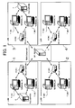
- Fig. 1 is a network configuration diagram of a relay communication system according to a preferred embodiment of the present invention.
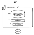
- Fig. 2 is a functional block diagram of an external server.
- Fig. 3 is a functional block diagram of a client terminal.
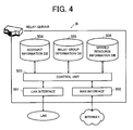
- Fig. 4 is a functional block diagram of a relay server.
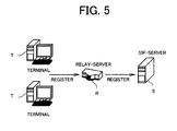
- Fig. 5 illustrates the relationship of the client terminal, the relay server, and the external server.
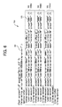
- Fig. 6 illustrates content of relay group information.
- Fig. 7 illustrates content of shared resource information.
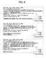
- Fig. 8 illustrates a specific example of message content information included in the shared resource information.
- Fig. 9 is a sequence chart illustrating a communication process for registering the relay server and the client terminal.
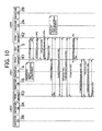
- Fig. 10 is a sequence chart illustrating a communication process for forming a relay group with three relay servers.
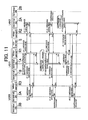
- Fig. 11 is a sequence chart illustrating a communication process for registering a shared resource in the relay group and exchanging messages.
- Fig. 12 is an explanation diagram of an example in which the message is displayed by using client software executed by the client terminal.
- Fig. 13 is an explanation diagram of an example in which the message is displayed by using the client software.
- Fig. 14 is a sequence chart illustrating a communication process performed when the shared resource held by the client terminal is indirectly deleted by a client terminal of another LAN.
- Fig. 15 illustrates an example of different content of the shared resource information.
- Fig. 1 is an explanation diagram illustrating an overall configuration of a relay communication system according to the preferred embodiment of the present invention.
- the relay communication system is configured by a plurality of LANs connected to a Wide Area Network (WAN).
- the relay communication system includes an external server S, a relay server R, a client terminal T, a file server F, and the like.
- the WAN is a network for connecting different LANs to each other.
- the Internet is used as the WAN.
- the LAN is a relatively small-scale network built in a limited location.
- the LAN exists in plurals, each of which being built at a physically remote location.
- a LAN 1 is built at Tokyo branch office
- LANs 2, 3, 4 are respectively built at Osaka branch office, Nagoya branch office, and Fukuoka branch office.
- Each of the four LANs 1, 2, 3, and 4 is connected to the Internet, which is a global network.
- Fig. 2 is a functional block diagram of the external server S.
- the external server S is equipment used for the communication between the relay servers R arranged in each LAN, and is installed on the Internet.
- the external server S illustrated in Fig. 2 has a function serving as a Session Initiation Protocol (SIP) server. Specifically, the external server S has a function serving as an SIP proxy server for relaying SIP methods and responses etc., and as an SIP registrar server for registering an account of the relay server R.
- SIP Session Initiation Protocol
- the external server S includes a WAN interface 201, a control unit 202, and a relay server account information database 203, as a main configuration.
- the WAN interface 201 is an interface for performing communication with each device such as the relay server R connected to the Internet, using a global IP address.
- the relay server account information database 203 is a database for managing the account of the relay server R that has made a registration request, in association with the global IP address.
- the control unit 202 is a processing unit for controlling various communications performed through the WAN interface 201, and controls communication processes complying with protocols such as TCP/IP, UDP and SIP.
- the control unit 202 executes processes such as a process of receiving the account of each relay server R from the relevant relay server R and registering the received account in the relay server account information database 203, and a process of relaying communication data such as various SIP methods and responses transmitted from the relay server R, to another relay server R.
- processes such as a process of receiving the account of each relay server R from the relevant relay server R and registering the received account in the relay server account information database 203, and a process of relaying communication data such as various SIP methods and responses transmitted from the relay server R, to another relay server R.
- the details of each function of the external server S centering on the control unit 202 will be described later.
- Fig. 3 is a functional block diagram of the client terminal T.
- the client terminal T is a terminal that can be directly operated by the user, and includes a personal computer (PC) and the like used by the user on a daily routine.
- PC personal computer
- a great number of client terminals T normally exist in the LAN, but in the present preferred embodiment, as illustrated in Fig. 1 , there will be described a case where client terminals 1A, 1B are connected to the LAN 1, client terminals 2A, 2B are connected to the LAN 2, client terminals 3A, 3B are connected to the LAN 3, and client terminals 4A, 4B are connected to the LAN 4, by way of example.
- a private IP address uniquely managed in the same LAN is given to each client terminal T.
- the client terminal T includes a LAN interface 601, a control unit 602, a resource storage unit 603, and a shared resource information database 604, as a main configuration.
- the LAN interface 601 is an interface for performing communication with each device such as the relay server R and the file server F connected to the same LAN, using the private IP address.
- the resource storage unit 603 stores entities of resources such as files and folders operable by the client terminal T.
- the shared resource information database 604 stores shared resource information held by each client terminal T and shared resource information in which message information etc. exchanged among each client terminal T is registered.
- the control unit 602 is a processing unit for controlling various communications performed through the LAN interface 601.
- the control unit 602 controls communication processes complying with protocols such as TCP/IP, UDP, and SIP.
- control unit 602 executes a process of controlling movement, change, deletion etc. of the resources stored in the resource storage unit 603.
- the control unit 602 also performs a process of updating the shared resource information stored in the shared resource information database 604 when a change notification of the shared resource information is received from the relay server R.
- the details of the functions of each client terminal T centering on the control unit 602 will be described later.
- Fig. 4 is a functional block diagram of each relay server R.
- a relay server R is arranged in each LAN. Specifically, a relay server R1 is arranged in the LAN 1, a relay server R2 is arranged in the LAN 2, a relay server R3 is arranged in the LAN 3, and a relay server R4 is arranged in the LAN 4.
- the relay server R is connected to the LAN, and can communicate with each client terminal T connected to the same LAN.
- the relay server R is also connected to the Internet, and can communicate with the relay servers R connected to the other LANs through the external server S. For such communication, both the private IP address and the global IP address are given to each relay server R.
- the relay server R includes a LAN interface 501, a WAN interface 502, a control unit 503, an account information database 504, a relay group information database 505, and a shared resource information database 506, as a main configuration.
- the LAN interface 501 is an interface for performing communication with the client terminal T connected to the same LAN as its own device, using the private IP address.
- the relay server R1 can communicate with each client terminal 1A, 1B by using the LAN interface 501 in the LAN 1.
- the WAN interface 502 is an interface for performing communication with each device such as the external server S connected to the Internet, using the global IP address.
- Each relay server R has a function serving as the SIP registrar server, and the communication between each relay server R and each client terminal T is performed using the SIP.
- the relay server R2 functions as the SIP registrar server in the LAN 2, receives the account of each client terminal 2A, 2B connected to the LAN 2, and registers the account in the account information database 504.
- the relay server R functions as a server for receiving the account from the relevant client terminal T and registering (REGISTER) the received account.
- the relay server R functions as a client for transmitting the account to the external server S and registering (REGISTER) the transmitted account.
- the account information database 504 in Fig. 4 is a database for managing the account of the client terminal T that has made a registration request, in association with the private IP address.
- the relay group information database 505 is a database for managing relay group information related to the client terminal T registered in the account information database 504.
- the shared resource information database 506 is a database for managing the shared resource information related to the client terminal T registered in the account information database 504.
- the control unit 503 is a processing unit for controlling various communications performed via the LAN interface 501 and the WAN interface 502, and controls various communication processes complying with protocols such as TCP/IP, UDP, and SIP.
- control unit 503 executes a process of transmitting the account of its own device to the external server S and requesting for registration, a process of creating the relay group information to store in the relay group information database 505, a process of creating the shared resource information to store in the shared resource information database 506, and the like.
- the details of each function of the relay server R centering on the control unit 503 and the like will be described later.
- the file server F will now be described. As illustrated in Fig. 1 , the file server F is connected to the LAN, and can communicate with each client terminal T connected to the same LAN.
- the file server F is configured to store the entities of resources such as files and folders, and functions as a resource storage unit alternative to the resource storage unit 603 ( Fig. 3 ) arranged in each client terminal T.
- the resource that can be operated by each client terminal T may be stored in a local disc of the relevant client terminal T, and/or may be stored in the file server F serving as a network drive.
- the file server F is not essential in each LAN, and the installation thereof is omitted in the LANs 2 and 4 in the example of Fig. 1 .
- the relay group information and the shared resource information which are information handled in the present relay communication system, will now be described.
- relay group information 100 stored in the relay group information database 505 includes one piece of group identifying information 101 and information (relay account information) 102 of the relay server R that forms a relay group by permitting connection with one another.
- the group identifying information 101 is information for identifying the relay group information 100, and is given a different ID so as to be uniquely identified each time the relay group information 100 is created. Therefore, an operator and the like can specify the relay group based on the group identifying information 101 and easily change etc. a group configuration.
- the relay account information 102 includes account information on each relay server R that forms the relay group by permitting connection with one another.
- the relay account information 102 includes the account information etc. of the client terminal T that is connected to the same LAN as each relay server R that forms the relay group and registered in the relay server R.
- relay account information 102 a specific name given to the account of each relay server R is also registered so as to be easily identified by the user.
- relay account information 102a of the relay server R1 relay-server 1
- the account (relay-server1@net) of the relay server R1 and a name (branch office A) given to the account are described.
- the specific name given to the account is also registered in a portion of the account of the client terminal T connected to the same LAN as the relay server R, so as to be easily identified by the user.
- a name (terminal 1A) given to the account for example, user1A@relay-server1.net
- division identifying data 103 indicating a division to which the client terminal T belongs, such as a sales division and a development division, is also described in the account of the client terminal T.
- the relay group information 100 is created to be uniquely identified with respect to each relay group.
- the relay group information 100 includes the account (relay account information 102) of each relay server forming a group (relay group) by permitting the connection with one another.
- the relay account information 102 includes the account information on the client terminal T registered in and connected to the same LAN as the relevant relay server.
- relay group information 100 it becomes apparent as to which LANs form the group, and as to which relay server R and client terminal T are registered in the relevant LANs.
- the relay group information 100 is exchanged between each relay server R that forms the relay group.
- Fig. 7 illustrates an example of shared resource information 120 stored in the shared resource information database 604 of the client terminal 1A.
- the same information is also stored in the shared resource information database 506 of the relay server R1 connected to the same LAN as the client terminal 1A.
- the shared resource information 120 includes account identifying information 121 indicating to be the shared resource information regarding the client terminal 1A, and individual shared resource information 122 related to the client terminal 1A.
- the shared resource information 120 is created with respect to each client terminal T, and the account identifying information 121 is information for identifying the shared resource information.
- the individual shared resource information 122 includes shared resource identifying information 123, family account information 124, family resource information 125, and message thread information 126 etc.
- the shared resource identifying information 123 is information for identifying the individual shared resource information 122, and is given a different ID each time the individual shared resource information 122 is created, so as to be uniquely identified.
- the shared resource identifying information 123 here includes an ID (e.g., 20061001150032user1A@relay-server1.net) associated with the client terminal T that has made a request to create the shared resource information 120, and a name (projectA) for facilitating the identification thereof.
- the user and the like can specify the individual shared resource information 122 based on the shared resource identifying information 123 and easily edit etc. the content thereof.
- the family resource information 125 is an aggregate of resource information 127 indicating entities of resources such as files and folders held by the client terminal T.
- the family account information 124 is an aggregate of information on the account (e.g., user1A@relay-server1.net) of the client terminal T that shares the entity of the resource indicated in the family resource information 125.
- the family account information 124 includes information on the owner client terminal T and information on the client terminal T (user client terminal) capable of indirectly operating the entity of the resource through the owner client terminal T.
- the user client terminal T cannot directly operate the entity of the resource, but can indirectly operate the resource through the owner client terminal T.
- the message thread information 126 is information for registering a series of messages that are exchanged in association with each resource registered in the resource information 127.
- Each message thread information 126 includes message thread identifying information 128 and message information 129.
- the message thread information 126 is created with respect to each thread, and the message thread identifying information 128 is information for identifying the message thread information.
- the resource information 127 and the message thread information 126 become associated with each other.
- the message information 129 is created each time one message is transmitted from the client terminal T.
- One or a plurality of message information 129 is registered in each message thread information 126.
- Each message information 129 includes message identifying information 130 and message content information 131.
- the message information 129 is created with respect to each message, and the message identifying information 130 is information for identifying the message information.
- the specific content of the message transmitted from the client terminal T is described in the message content information 131. Although simply illustrated in Fig. 7 , contents of message content information 131a, 131b, and 131c are illustrated in Fig. 8 in detail. As illustrated in Fig. 8 , in the present preferred embodiment, the message content information 131 is described in a format complying with a publicly-known e-mail format.
- the message content information 131 includes a header 132 and a body 133.
- the header 132 includes transmission date and time of the message (Date header), a transmission source (From header), a transmission destination (To header), a subject name (Subject header), an identifying ID (Message-Id header), information on encoding of the message (MIME-Version header), and the like.
- the content of body text of the message is described in the body 133.
- a character string created by performing Multipurpose Internet Mail Extensions (MIME) encoding on a Japanese text message is described in the body 133.
- MIME Multipurpose Internet Mail Extensions
- the shared resource information database 506 included in the relay server R is arranged to store the shared resource information 120 ( Fig. 7 ) containing the family resource information 125 describing the resource information and the family account information 124 describing the account of the client terminal T that shares the resource. Moreover, the shared resource information 120 can register a series of message information 129 therein in association with each resource (resource information 127) described in the family resource information 125.
- the relay server R1 transmits a registration request (REGISTER) of the account to the external server S.
- the relay server R1 makes a request for registration of the account (sip: relay-serverl@net) of its own device.
- the external server S returns an OK response to the relay server R1, and registers the account of the relay server R1 and the global IP address of the relay server R1 in the relay server account information database 203 in association with each other.
- the relay servers R2 and R3 make a registration request (REGISTER) of the account of its own device to the external server S to register the account etc. of its own device in the external server S (sequence numbers 2, 3).
- the client terminal 2A transmits a registration request (REGISTER) of the account to the relay server R2.
- the client terminal 2A makes a request for registration of the account (sip: user2A@relay-server2.net) of its own device.
- the relay server R2 returns an OK response, and registers the account and the private address of the client terminal 2A in the account information database 504 in association with each other.
- the client terminals 1A, 3A, 2B, 1B, and 3B make a request for registration of the account of its own device to the respective relay servers R to register the account etc. of its own device in the relay server R (sequence numbers 5 through 9).
- the registration of the account of each relay server R in the external server S and registration of the account of each client terminal T in the relay server R are completed through the above processes.
- the sequence described above is an example, and the order may be arbitrarily set as long as the registration of the account of each device is completed as a result.
- the relay server R and the client terminal T existing on the network cannot participate in the relay communication system of the present preferred embodiment unless the account thereof is registered.
- the relay server R4 and the client terminals 4A, 4B of Fig. 1 cannot participate in the communication described below because the account registration thereof is not performed in the process of Fig. 9 .
- sequence numbers 10 through 18 of Fig. 10 The processes of sequence numbers 1 through 18 illustrated in Figs. 9 and 10 are generally carried out as initial setting of the network by the user or the operator.
- a METHOD (createGroup METHOD) for newly forming a relay group with the relay server R2 is executed by the operator.
- createGroup METHOD there are specified a group name (group1), the account (relay-server2@net) of the relay server R2 with which the relay group is formed, and an identification ID (groupID0001) given to the newly created relay group.
- a message transmission command (MESSAGE METHOD) is then executed in the relay server R1, and a group-info message with respect to the relay server R2 is transmitted to the external server S (sequence number 10).
- This message contains the group name, the identification ID of the relay group, and the like specified in the createGroup METHOD.
- the account (sip: relay-server2@net) of the relay server R2 of a message transmission destination is specified.
- the external server S acquires the global IP address of the relay server R2 by referencing the relay server account information database 203, and relays the group-info message from the relay server R1 to the relay server R2. Having received the message, the relay server R2 returns an OK response to the relay server R1 through the external server S.
- each relay server R of the present preferred embodiment is thus performed through the external server S, and is the same in the following description. Therefore, specific description of the communication process through the external server S will be omitted in the following description.
- the relay server R1 then transmits a transmission request message (request-server-info message) of server information to the relay server R2 (sequence number 11). Having received the message, the relay server R2 returns the information (server-info) of its own device to the relay server R1 along with an OK response.
- a transmission request message (request-server-info message) of server information
- the relay server R2 Having received the message, the relay server R2 returns the information (server-info) of its own device to the relay server R1 along with an OK response.
- the relay server R2 transmits a request-server-info message to the relay server R1 (sequence number 12), and the relay server R1 returns the information (server-info) of its own device to the relay server R2.
- the relay group information 100 indicating that the relay servers R1, R2 have formed the relay group is generated, and stored in the relay group information database 505 of each relay server R1, R2.
- a METHOD (addGroup METHOD) of newly adding the relay server R3 to the previously created relay group (relay group configured by the relay servers R1, R2) is executed by the operator.
- the group name (group1) of the relay group to be added to, the account (relay-server3@net) of the relay server R3 to be added, and the identification ID (groupID0001) of the relay group to be added to are specified.
- the relay server R2 transmits a group-info message to the relay server R3 to be added (sequence number 13).
- This message contains the group name, the identification ID of the relay group, and the like specified in the addGroup METHOD. Having received the message, the relay server R3 returns an OK response to the relay server R2.
- the server information is exchanged between the relay server R2 and the relay server R3 (sequence numbers 14, 15) in a manner exactly similar to the above-described sequence numbers 11 and 12.
- the relay server R2 transmits an update-group-info message notifying that the relay server R3 has been added to the relay group, to the relay server R1 (sequence number 16). Having received the message, the relay server R1 returns an OK response to the relay server R2. Thereafter, the server information is exchanged between the relay server R3 and the relay server R1 (sequence numbers 17, 18).
- the relay group information 100 (specifically, information on the content illustrated in Fig. 6 ) indicating that the three relay servers R1, R2, and R3 form the relay group is stored in the relay group information database 505 of each relay server R1, R2, and R3.
- the user operates the client terminal 1A and instructs the client terminal 1A to display a list of client terminals that can share the files with the client terminal 1A. Accordingly, the client terminal 1A references the stored content (relay group information 100) of the relay group information database 505 to display on a screen the list of client terminals T that are connected to the LAN to which any of the relay servers R forming the relay group with the relay server R1 in the same LAN is connected.
- the five client terminals 1B, 2A, 2B, 3A, and 3B are displayed as the terminals that can share the files, based on the content of the relay group information 100 of Fig. 6 .
- the user can specify the client terminal (the user client terminal) for actually sharing the resource, from the displayed five terminals.
- the user specifies the client terminals 2A and 3A to share the files.
- the client terminal 1A then transmits a request to create the shared resource (CreateSharedResource command) to the relay server R1 (sequence number 21 of Fig. 11 ).
- This message contains the group identifying information 101 and the information on the specified user client terminals 2A and 3A.
- the relay server R1 Having received the message, the relay server R1 creates the shared resource information 120 to store in the shared resource information database 506 of its own device.
- the relay server R1 references the content of the relay group information database 505 based on the identifying ID of the relay group, transmits a policy-data message to the other relay servers R2, R3 forming the relay group, and notifies of the created shared resource information 120 (sequence numbers 21.1, 21.2).
- each relay server R2, R3 stores the shared resource information 120 in the shared resource information database 506 of its own device, transmits the policy-data message to each specified user client terminal 2A, 3A, and notifies of the shared resource information 120 (sequence numbers 21.1.1, 21.2.1).
- each user client terminal 2A, 3A changes the shared resource information 120 stored in the shared resource information database 604 of its own device, and returns an OK response to the relay servers R2, R3 of transmission source.
- the relay servers R2, R3 return an OK response to the relay server R1, and having received the OK response, the relay server R1 returns an OK response to the client terminal 1A.
- the shared resource identifying information 123 and the family account information 124 have been described in the shared resource information 120 stored in the shared resource information database 506 of the relay servers R1, R2, and R3. The same content is also described in the shared resource information 120 stored in the shared resource information database 604 of the client terminals 1A, 2A, and 3A. Thus, a virtual field in which the client terminals 1A, 2A, and 3A participate over the respective LANs is formed.
- the transmission destination (the terminal that will publicize the message) of the message can be arbitrarily selected and specified from the client terminals 2A and 3A, which share the "folderA".
- the user specifies both the client terminals 2A and 3A as the transmission destinations.
- the client terminal 1A for which the user has performed the above operation changes the content of the shared resource information 120 stored in the shared resource information database 604, based on the specified content.
- the resource information 127 regarding the "folderA” etc. and the message information 129 regarding the "creation of workspace for project A" are registered in the shared resource information 120.
- Reference numeral 131a of Fig. 8 denotes an example of message content information on the message information 129.
- the account of the client terminal 1A is recorded in a portion of the transmission source (From header), and the accounts of the client terminals 2A and 3A, which are message publicizing terminals, are recorded in a portion of the transmission destination (To header), in the header 132.
- the information on the transmission date and time etc. is described in the header 132 as well as the information on the encoded subject name and body text.
- the client terminal 1A transmits a shared resource change request (UpdateSharedResource command) including the content of the changed shared resource information 120 to the relay server R1 (sequence number 31 of Fig. 11 ). Having received the shared resource change request, the relay server R1 stores the changed shared resource information in the shared resource information database 506 of its own device. Accordingly, the resource information 127 and the message information 129 are registered in the shared resource information 120 stored in the shared resource information database 506 of the relay server R1.
- a shared resource change request (UpdateSharedResource command) including the content of the changed shared resource information 120 to the relay server R1 (sequence number 31 of Fig. 11 ).
- the relay server R1 transmits the policy-data message to the relay servers R2 and R3 respectively connected to the user client terminals 2A and 3A, and notifies of the changed shared resource information 120 (sequence numbers 31.1 and 31.2).
- each relay server R2 and R3 stores the shared resource information 120 in the shared resource information database 506 of its own device, as well as to transmit the policy-data message to each specified user client terminal 2A and 3A to notify of the shared resource information 120 (sequence numbers 31.1.1 and 31.2.1).
- each user client terminal 2A, 3A that has received the message changes the shared resource information 120 stored in the shared resource information database 604 of its own device, and analyzes the message information 129 included in the shared resource information 120. Then, each user client terminal 2A and 3A determines whether or not the message is for its own device (whether or not its own device is the message publicizing terminal for the message), based on the information on the transmission destination (the content of To header) described in the header 132 of the message information 129. Then, when the message is for its own device, the relevant client terminal executes a viewMessage METHOD to display the message.
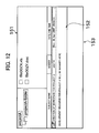
- Fig. 12 illustrates the message displayed on the client terminal T.
- Fig. 12 illustrates a screen display image of client software executed by the client terminal 2A.
- client software information regarding the shared resource is displayed on an upper side portion (upper pane 151), a list of messages of the message thread regarding the shared resource is displayed on a middle section (middle pane 152), and the content of the selected message is displayed on a lower side portion (lower pane 153).
- the upper pane 151 is divided into right and left, and a folder structure of the shared resource is displayed in a tree view on the left side.
- a folder structure of the shared resource is displayed in a tree view on the left side.
- the folder “folderA” is shared under the name of "projectA-folder” (refer to the shared resource information 120 of Fig. 7 )
- the shared folder is displayed under the name of "projectA-folder” on the client software.
- the shared files in the shared folder are displayed in a view format on the right side of the upper pane 151.
- the file "file001.xls” is shared under the name of "file00ZX.xls”
- the file "file002.doc” is shared under the name of "file00ZX.xls”.
- the two shared files "file00ZX.xls” and "file00ZY.doc” are displayed as illustrated in Fig. 12 .
- the shared folder selected in the upper pane 151 or the list of messages associated with the shared file is displayed in the middle pane 152.
- Fig. 12 illustrates a state in which the user has selected the "projectA-folder” in the upper pane 151. Accordingly, a list of summary of the message associated with the "projectA-folder” is displayed in the middle pane 152.
- the subject name "creation of workspace for project A”, a transmitter "user1A”, and the transmission date and time thereof "Mon, 02 Apr 2007 10:04:54” are displayed.
- Fig. 12 illustrates a state in which the user has selected the message with the subject name "creation of workspace for project A”. Accordingly, the body text of the message, "development resource for the project A will be managed here", is displayed on the lower pane 153.
- the client terminal 1A also shares the same resource with the client terminal 3A, and transmits the same message to the client terminal 3A (refer to the shared resource information 120 of Figs. 7 and 8 ) . Therefore, a displaying screen of the client terminal 3A is virtually similar to a displaying screen of the client terminal 2A illustrated in Fig. 12 .
- the client terminals 2A and 3A respectively returns an OK response to the relay servers R2 and R3, which are transmission sources. Having received the OK response, the relay servers R2 and R3 returns an OK response to the relay server R1. Having received the OK response, the relay server R1 returns an OK response to the client terminal 1A.
- the user performs an operation of transmitting a new message in association with the already shared resource "file001.xls" to the client terminals 2A and 3A.
- the subject name of the message is "schedule file”, and a body text of certain content is included in the message.
- the content of the new message is added as the message information 129 to the shared resource information 120, and a process virtually similar to sequence numbers 31 through 31.2.1 is performed.
- the client software of the client terminals 2A and 3A displays on the respective screens the message with the subject name "schedule file".
- the user of the client terminal 2A transmits a message with the subject name "Re: schedule file” and the body text "Confirmed" to the client terminals 1A and 3A as the destinations in response to the message with the subject name "schedule file”.
- the client terminal 2A changes the content of the shared resource information 120 stored in the shared resource information database 604, based on the content of the return message.
- the message information 129 regarding "Re: schedule file” is additionally registered in the portion of the message thread identical to the message with the subject name "schedule file”.
- the client terminal 2A then transmits a shared resource change request (UpdateSharedResource command) including the content of the changed shared resource information 120 to the relay server R2 (sequence number 41 of Fig. 11 ).
- a shared resource change request (UpdateSharedResource command) including the content of the changed shared resource information 120
- the relay server R2 Having received the shared resource change request, the relay server R2 stores the changed shared resource information in the shared resource information database 506 of its own device. Accordingly, the resource information 127 and the message information 129 are also registered in the shared resource information 120 stored in the shared resource information database 506 of the relay server R2.
- the relay server R2 then transmits a policy-data message to the relay servers R1 and R3 to which the user client terminals 1A and 3A are respectively connected, and notifies of the changed shared resource information 120 (sequence numbers 41.1 and 41.2).
- each relay server R1 and R3 stores the shared resource information 120 in the shared resource information database 506 of its own device, transmits the policy-data message to each specified user client terminals 1A and 3A, and notifies of the shared resource information 120 (sequence numbers 41.1.1 and 41.2.1).
- each user client terminal 1A and 3A changes the shared resource information 120 stored in the shared resource information database 604 of its own device, and analyzes the message information 129 included in the shared resource information 120. Then, each user client terminal 1A and 3A determines whether or not the message is for its own device, based on the information (content of To header) of the transmission destination described in the header 132 of the message information 129. If the message is for its own device, the relevant user client terminal executes the viewMessage METHOD to display the message.
- Fig. 13 illustrates a display screen image of the client software of the client terminal 3A. As illustrated in Fig. 13 , when “file00ZX.xls" is selected in the upper pane 151, two messages of the message thread associated with the shared file “file00ZX.xls” are displayed on the middle pane 152. Fig. 13 illustrates a state in which the message with the subject name "Re: schedule file” has been selected from the two messages, and the content of the body text of the message, "confirmed", is displayed on the lower pane 153.
- the relay communication system including, as the constituent element, the relay server R of the present preferred embodiment can share the resource over the LAN and exchange the messages in association with the resource.
- the sharing of the resource and the exchanging of the messages regarding the sharing can be uniquely and integrally performed, thereby saving the user of the trouble of information management.
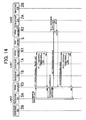
- the client terminal 3A transmits a file delete request (DeleteFile command) to the relay server R3 (sequence number 51 of Fig. 14 ).
- the relay server R3 specifies the owner client terminal T, which holds the file "file001.xls" to be deleted and can delete the file, and the relay server R connected to the owner client terminal T.
- the shared resource information 120 stored in the shared resource information database 506 and the relay group information 100 stored in the relay group information database 505 are referenced.
- the owner client terminal is the terminal 1A
- the relay server connected to the terminal 1A is the relay server R1, based on the shared resource information 120 in Fig. 7 and the relay group information 100 in Fig. 6 .
- the relay server R3 transmits the delete message to the relay server R1 and relays the instruction for file deletion (sequence number 51.1).
- the relay server R1 Having received the delete message from the relay server R3, the relay server R1 transmits the file delete request (DeleteFile command) to the client terminal 1A (sequence number 51.1.1). Having received the request, the client terminal 1A deletes the resource (file001.xls) to be deleted from the resource storage unit 603, and returns an OK response to the relay server R1. Having received the OK response, the relay server R1 returns an OK response to the relay server R3. Having received the response, the relay server R3 returns an OK response to the client terminal 3A.
- the file delete request (DeleteFile command)
- the client terminal 1A deletes the resource (file001.xls) to be deleted from the resource storage unit 603, and returns an OK response to the relay server R1. Having received the OK response, the relay server R1 returns an OK response to the relay server R3. Having received the response, the relay server R3 returns an OK response to the client terminal 3A.
- An updating process of the shared resource information 120 is then performed. Specifically describing, the client terminal 3A, which has instructed deletion of the file, deletes the resource information 127 regarding the deleted resource (file001.xls) from the family resource information 125 of the shared resource information 120 stored in the shared resource information database 604. At this time, the message thread information 126 associated with the deleted resource (file001.xls) and the message information 129 included in the message thread information 126 are also deleted. In this case, the message of the message thread associated with the "file001.xls" is the message with the subject name "schedule file" and the message with the subject name "Re: schedule file". Accordingly, the message information 129 regarding these two messages is deleted.
- the client terminal 3A then transmits a shared resource change request (UpdateSharedResource command) to the relay server R3 (sequence number 52). Having received the change request, the relay server R3 then transmits the policy-data message to the relay servers R1, R2, which are related to the changed shared resource information 120, and notifies of the changed shared resource information 120 (sequence number 52.1, 52.2).
- a shared resource change request (UpdateSharedResource command)
- the relay server R3 transmits the policy-data message to the relay servers R1, R2, which are related to the changed shared resource information 120, and notifies of the changed shared resource information 120 (sequence number 52.1, 52.2).
- each relay server R1, R2 stores the shared resource information 120 in the shared resource information database 506 of its own device, transmits the policy-data message to each user client terminal 1A, 2A, which is related to the shared resource 120, and notifies of the shared resource information 120 (sequence numbers 52.1.1, 52.2.1).
- each user client terminal 1A, 2A changes the shared resource information 120 stored in the shared resource information database 604 of its own device, and returns an OK response to the relay servers R1, R2 of the transmission source.
- the relay servers R1, R2 returns an OK response to the relay server R3, and the relay server R3, which has received the OK response, returns an OK response to the client terminal 3A.
- the shared resource information 120 is changed, such change is notified to the related relay server R and client terminal T so that the shared resource information 120 will be immediately updated to the new shared resource information 120.
- the change by which the shared resource is deleted is performed, the change by which the message information 129 regarding the shared resource is deleted is automatically performed in the shared resource information 120.
- the relay server R connected to the LAN in this preferred embodiment is arranged to relay the operation instruction regarding the resource to the other relay server R based on the relay group information 100.
- the relay server R3 receives an instruction to delete the resource "file001.xls" operable by the client terminal 1A of the other LAN from the client terminal 3A, as illustrated in sequence number 51.1 of Fig. 14 , the relay server R is arranged to relay the deletion instruction to the other relay server R1.
- the message information 129 regarding the message to be transmitted by the client terminal T can be included in the shared resource information 120 stored in the shared resource information database 506 of the relay server R. It is also arranged such that when the message is transmitted by the client terminal T stored in the account information database 504, the relay server R relays the message information 129 regarding the message to the other relay server R based on the shared resource information 120 and the relay group information 100. For example, when the client terminal 1A transmits the message, as illustrated in sequence numbers 31. 1 and 31.2 of Fig. 11 , the relay server R1 relays the message information 129 regarding the message to the other relay servers R2 and R3.
- the client terminals 1A, 2A, and 3A can form a virtual field, and the resource of the client terminal 1A can be shared.
- the messaging among the client terminals 1A, 2A, and 3A can be achieved.
- the client terminal T which shares the resource, can transmit a new message in response to the message.
- the client terminal 2A one (the client terminal 2A) of the three client terminals, which share the resource "file001.xls" associated with the message of subject name "schedule file”, transmits the message of subject name "Re: schedule file” by the addMessage METHOD of Fig. 11 , in response to the above message.
- the relay server R2 relays the message information 129 regarding the new message to the other relay servers R1 and R3 based on the shared resource information 120 and the relay group information 100 (sequence numbers 41.1 and 41.2).
- each client terminal T which shares the resource over the LAN, can exchange user opinions etc. by sequentially adding the messages. Accordingly, dense, duplex communication can be achieved, thereby improving the efficiency of cooperative work.
- the message information 129 can be registered in association with each shared resource information 120 in the shared resource information 120 stored in the shared resource information database 506 of the relay server R.
- the message information 129 is stored in the shared resource information database 506 of the relay server R in association with the shared resource, the resource and the message can be easily managed integrally.
- the relay server R of the present preferred embodiment when the client terminal T, which shares the resource, deletes the resource, the shared resource information 120 stored in the shared resource information database 506 is updated, and the message information 129 associated with the deleted resource is deleted.
- the message information 129 related to the two messages (with the subject name "schedule file” and "Re: schedule file") of the message thread associated with the resource is deleted in the shared resource information 120 stored in the shared resource information database 506 in the relay servers R1, R2, and R3.
- the shared resource and the message can be integrally managed further easily, thereby saving the trouble of information management.
- the client terminal T transmits the message in association with the resource
- the destination (message publicizing terminal) can be specified from the client terminals that share the resource.
- the account of the message publicizing terminal can be included in the header 132 (To header) of the message content information 131.
- the message may be deleted independently of the associated shared resource. Further, the message received from another client terminal T may be deleted separately in each client terminal T.
- the message information 129 is associated with respect to each shared resource, however, as illustrated in Fig. 15 , for example, the message information 129 may be associated with respect to all of the shared resource information 120.
- one message thread can be registered in association with respect to all of the plurality of shared resources ("folderA”, "file001.xls", and "file002.doc").
- the client software executed by the client terminal T is not limited to be displayed on the screen illustrated in Fig. 12 , but may be applied to other various user interfaces.
- the content of the message is not limited to be in the publicly-known e-mail format illustrated in Fig. 8 , but may be modified to be described in the shared resource information 120 in other formats such as an XML format.
- the relay server R forming the relay group may be arbitrarily selected. Further, a plurality of relay groups may be formed to be stored in the relay group information database 505.
- the number of LANs merely needs to be in plurals and is not limited to four. Similar network other than the Internet may be used as the WAN.
- a protocol other than the SIP may be used for the communication protocol between the external server S and each relay server R in the WAN, and between the relay server R and the client terminal T etc. in the LAN.
- the external server S may be omitted, and communication may be directly carried out between the relay servers R.
- the communication between the relay servers R may be directly controlled based on the protocol, and thus the external server S can be easily omitted.
- the external server S is not limited to one, and may dispersively function in plurals.
- the WAN interface 502 of the relay server R may be omitted. In such a case, the connection with the Internet is performed by a router, and the relay server R may be arranged thereunder.
- the client terminal T connected to the same LAN as the relay server R is stored in the account information database 504 of the relay server R.
- the client terminal T connected to the LAN different from its own device may be stored in the account information database 504.
- the relay server R and the client terminal T registered in the account information database 504 of the relay server R may be in any relation as long as they can communicate with each other through the network.
- a plurality of relay servers R may be connected to the same LAN. For example, it may be arranged such that three relay servers R are provided in the same LAN, some client terminals T in the LAN are stored in the account information database 504 of the first relay server R, and some of the other client terminals T are stored in the account information database 504 of the second relay server R. In this case, the three relay servers R communicate through the LAN, and the relay is completed within one LAN.
Landscapes
- Engineering & Computer Science (AREA)
- Business, Economics & Management (AREA)
- Human Resources & Organizations (AREA)
- Strategic Management (AREA)
- Entrepreneurship & Innovation (AREA)
- Marketing (AREA)
- Quality & Reliability (AREA)
- Computer Hardware Design (AREA)
- Signal Processing (AREA)
- Economics (AREA)
- Computer Networks & Wireless Communication (AREA)
- Operations Research (AREA)
- Data Mining & Analysis (AREA)
- Tourism & Hospitality (AREA)
- Physics & Mathematics (AREA)
- General Business, Economics & Management (AREA)
- General Physics & Mathematics (AREA)
- Theoretical Computer Science (AREA)
- Information Transfer Between Computers (AREA)
- Data Exchanges In Wide-Area Networks (AREA)
- Computer And Data Communications (AREA)
Abstract
Description
- This application claims priority to Japanese Patent Application No.
2007-121877 filed on May 2, 2007 2007-152119 filed on June 7, 2007 - The present invention mainly relates to a configuration of a relay server that enables communication between terminals.
- A communication technique referred to as a Virtual Private Network (VPN) is conventionally known. The VPN is used, for example, for communication over the Internet between terminals connected to a Local Area Network (LAN) of a plurality of branch offices (base points) established in each region. Through the use of the VPN, another LAN in a remote location can be used as if a directly connected network.
- As a method for exchanging a file with a destination that is inside and/or outside the VPN, for example, a method for transmitting an electronic mail with a proper text message described therein and the file attached thereto is also known. It is also common to adopt methods for uploading the file by using a File Transfer Protocol (FTP) service, and for sending by mail a recording medium such as a CD-Recordable in which the file is recorded, or the like.
- However, when using the method for transmitting the file attached to the electronic mail, the e-mail is managed in a mailbox, and it is necessary to organize and store the attached file each time in a desired folder. Moreover, when a file size is large, it is necessary to set a mail server, and compress or divide the file due to limitations of a mailbox size. Accordingly, a receiving side is required to perform a decompression process or a connecting process, and such operations have been troublesome.
- When using the FTP service, although the service is suitable for the transmission of large files, troublesome operations such as setting an account for the FTP service have been necessary. Alternatively, when sending by mail the large file recorded in the recording medium such as the CD-Recordable, the cost for such media and for mailing can be expensive, causing cost increase.
- When adopting the FTP service or mailing method etc., if a message is desired to be transmitted along with the file, the message has to be transmitted separately via the electronic mail etc., causing troublesome work. Moreover, a side receiving the message and the file is required to manage the received file by using file managing software such as the Explorer, and to manage the message by using e-mail software. Therefore, there has been room for improvement in terms of simplification of information management.
- The problems to be solved by the present invention are as described above, and the methods for solving such problems and the effects thereof will be described below.
- According to a first aspect of the present invention, there is provided a relay server with the following configuration. The relay server includes an account information registering unit, a relay group information registering unit, and a shared resource information registering unit. The account information registering unit stores account information on a client terminal. The relay group information registering unit stores relay group information containing information on a group of relay servers that permit connections among each other. The shared resource information registering unit stores shared resource information containing resource information and information on the client terminals that share a relevant resource. When an operation instruction regarding the resource that can be operated by another client terminal is received from the client terminal stored in the account information registering unit, the relay server relays the operation instruction regarding the resource based on the relay group information. The shared resource information stored in the shared resource information registering unit can include message information regarding a message to be transmitted by the client terminal. When the message is transmitted by the client terminal stored in the account information registering unit, the message information regarding the message is relayed based on the shared resource information and the relay group information.
- With the above-described configuration, each client terminal can form a virtual field with a desired destination via the relay server so as to share, if necessary, the resource held by each client terminal, and also, messaging among users that participate in the field can be achieved.
- The relay server preferably includes the following configuration. The client terminals that share the resource are arranged to be able to transmit a new message in response to the message. When the new message is transmitted by the client terminal stored in the account information registering unit, the relay server is arranged to relay the message information regarding the new message based on the shared resource information and the relay group information.
- With the above-described configuration, each client terminal that shares the resource can exchange user opinions etc. by adding messages. Therefore, dense, duplex communication can be achieved, thereby improving efficiency of cooperative work.
- In the relay server, the shared resource information stored in the shared resource information registering unit is preferably arranged to be able to register the message information therein in association with the resource.
- With the above-described configuration, since the message information is stored in association with the shared resource, the resource and the message can be easily managed in an integrated manner.
- It is preferable to arrange such that in the relay server, when the client terminal that shares the resource deletes the resource, the shared resource information stored in the shared resource information registering unit is updated, and the message information associated with the deleted resource is also deleted.
- With the above-described configuration, the management of the shared resource and the message in the integrated manner is further facilitated, and therefore, troublesome information management can be simplified.
- The relay server preferably includes the following configuration. When the client terminal transmits the message in association with the resource, a message publicizing terminal can be specified from the client terminals that share the resource. The message information can include account information on the message publicizing terminal.
- With the above-described configuration, since publicizing/unpublicizing of individual messages can be easily specified with respect to each client terminal, flexible information management can be achieved.
- According to a second aspect of the present invention, there is provided a relay communication system including the following configuration. The relay communication system includes a plurality of relay servers, and each of the relay servers has an account information registering unit, a relay group information registering unit, and a shared resource information registering unit. The account information registering unit stores account information on a client terminal. The relay group information registering unit stores relay group information containing information on a group of relay servers that permit connections among each other. The shared resource information registering unit stores shared resource information containing resource information and information on the client terminals that share a relevant resource. When an operation instruction regarding the resource that can be operated by another client terminal is received from the client terminal stored in the account information registering unit, the relay server relays the operation instruction regarding the resource based on the relay group information. The shared resource information stored in the shared resource information registering unit can include message information on a message to be transmitted by the client terminal. When the message is transmitted by the client terminal stored in the account information registering unit, the message information regarding the message is relayed based on the shared resource information and the relay group information. Accordingly, it can be arranged such that the resource held by the client terminal stored in the account information registering unit of a certain relay server can be indirectly operated by the other client terminal, and further, the message can be transmitted to the other client terminal.
- With the above-described configuration, each client terminal can form a virtual field with a desired destination via the plurality of relay servers so as to share, if necessary, the resource held by each client terminal, and also, messaging among users that participate in the field can be achieved.
- It is preferable to arrange such that in the relay communication system, the shared resource information stored in the shared resource information registering unit of the relay server can register the message information therein in association with the resource.
- With the above-described configuration, since the message information is stored in association with the shared resource, the user does not have to perform troublesome operations, and the resource and the message can be managed in an integrated manner.
- Other features, elements, processes, steps, characteristics and advantages of the present invention will become more apparent from the following detailed description of preferred embodiments of the present invention with reference to the attached drawings.
-
Fig. 1 is a network configuration diagram of a relay communication system according to a preferred embodiment of the present invention. -
Fig. 2 is a functional block diagram of an external server. -
Fig. 3 is a functional block diagram of a client terminal. -
Fig. 4 is a functional block diagram of a relay server. -
Fig. 5 illustrates the relationship of the client terminal, the relay server, and the external server. -
Fig. 6 illustrates content of relay group information. -
Fig. 7 illustrates content of shared resource information. -
Fig. 8 illustrates a specific example of message content information included in the shared resource information. -
Fig. 9 is a sequence chart illustrating a communication process for registering the relay server and the client terminal. -
Fig. 10 is a sequence chart illustrating a communication process for forming a relay group with three relay servers. -
Fig. 11 is a sequence chart illustrating a communication process for registering a shared resource in the relay group and exchanging messages. -
Fig. 12 is an explanation diagram of an example in which the message is displayed by using client software executed by the client terminal. -
Fig. 13 is an explanation diagram of an example in which the message is displayed by using the client software. -
Fig. 14 is a sequence chart illustrating a communication process performed when the shared resource held by the client terminal is indirectly deleted by a client terminal of another LAN. -
Fig. 15 illustrates an example of different content of the shared resource information. - Preferred embodiments of the present invention will now be described with reference to the drawings.
Fig. 1 is an explanation diagram illustrating an overall configuration of a relay communication system according to the preferred embodiment of the present invention. - As illustrated in
Fig. 1 , the relay communication system is configured by a plurality of LANs connected to a Wide Area Network (WAN). The relay communication system includes an external server S, a relay server R, a client terminal T, a file server F, and the like. - The WAN is a network for connecting different LANs to each other. In the present preferred embodiment, the Internet is used as the WAN.
- The LAN is a relatively small-scale network built in a limited location. The LAN exists in plurals, each of which being built at a physically remote location. In the present preferred embodiment, there is considered a case where a
LAN 1 is built at Tokyo branch office, andLANs LANs - The external server S will now be described with reference to
Fig. 2 etc.Fig. 2 is a functional block diagram of the external server S. The external server S is equipment used for the communication between the relay servers R arranged in each LAN, and is installed on the Internet. - The external server S illustrated in
Fig. 2 has a function serving as a Session Initiation Protocol (SIP) server. Specifically, the external server S has a function serving as an SIP proxy server for relaying SIP methods and responses etc., and as an SIP registrar server for registering an account of the relay server R. - As illustrated in
Fig. 2 , the external server S includes aWAN interface 201, acontrol unit 202, and a relay serveraccount information database 203, as a main configuration. - The
WAN interface 201 is an interface for performing communication with each device such as the relay server R connected to the Internet, using a global IP address. - The relay server
account information database 203 is a database for managing the account of the relay server R that has made a registration request, in association with the global IP address. - The
control unit 202 is a processing unit for controlling various communications performed through theWAN interface 201, and controls communication processes complying with protocols such as TCP/IP, UDP and SIP. For example, thecontrol unit 202 executes processes such as a process of receiving the account of each relay server R from the relevant relay server R and registering the received account in the relay serveraccount information database 203, and a process of relaying communication data such as various SIP methods and responses transmitted from the relay server R, to another relay server R. The details of each function of the external server S centering on thecontrol unit 202 will be described later. - The client terminal T will be described with reference to
Fig. 3 etc.Fig. 3 is a functional block diagram of the client terminal T. - The client terminal T is a terminal that can be directly operated by the user, and includes a personal computer (PC) and the like used by the user on a daily routine. A great number of client terminals T normally exist in the LAN, but in the present preferred embodiment, as illustrated in
Fig. 1 , there will be described a case whereclient terminals LAN 1,client terminals LAN 2,client terminals LAN 3, andclient terminals LAN 4, by way of example. A private IP address uniquely managed in the same LAN is given to each client terminal T. - As illustrated in
Fig. 3 , the client terminal T includes aLAN interface 601, acontrol unit 602, aresource storage unit 603, and a sharedresource information database 604, as a main configuration. - The
LAN interface 601 is an interface for performing communication with each device such as the relay server R and the file server F connected to the same LAN, using the private IP address. - The
resource storage unit 603 stores entities of resources such as files and folders operable by the client terminal T. - The shared
resource information database 604 stores shared resource information held by each client terminal T and shared resource information in which message information etc. exchanged among each client terminal T is registered. - The
control unit 602 is a processing unit for controlling various communications performed through theLAN interface 601. Thecontrol unit 602 controls communication processes complying with protocols such as TCP/IP, UDP, and SIP. - For example, the
control unit 602 executes a process of controlling movement, change, deletion etc. of the resources stored in theresource storage unit 603. Thecontrol unit 602 also performs a process of updating the shared resource information stored in the sharedresource information database 604 when a change notification of the shared resource information is received from the relay server R. The details of the functions of each client terminal T centering on thecontrol unit 602 will be described later. - The relay server R will now be described with reference to
Fig. 4 etc.Fig. 4 is a functional block diagram of each relay server R. - As illustrated in
Fig. 1 , one relay server R is arranged in each LAN. Specifically, a relay server R1 is arranged in theLAN 1, a relay server R2 is arranged in theLAN 2, a relay server R3 is arranged in theLAN 3, and a relay server R4 is arranged in theLAN 4. - The relay server R is connected to the LAN, and can communicate with each client terminal T connected to the same LAN. The relay server R is also connected to the Internet, and can communicate with the relay servers R connected to the other LANs through the external server S. For such communication, both the private IP address and the global IP address are given to each relay server R.
- As illustrated in
Fig. 4 , the relay server R includes aLAN interface 501, aWAN interface 502, acontrol unit 503, anaccount information database 504, a relaygroup information database 505, and a sharedresource information database 506, as a main configuration. - The
LAN interface 501 is an interface for performing communication with the client terminal T connected to the same LAN as its own device, using the private IP address. For example, the relay server R1 can communicate with eachclient terminal LAN interface 501 in theLAN 1. - The
WAN interface 502 is an interface for performing communication with each device such as the external server S connected to the Internet, using the global IP address. - Each relay server R has a function serving as the SIP registrar server, and the communication between each relay server R and each client terminal T is performed using the SIP. For example, the relay server R2 functions as the SIP registrar server in the
LAN 2, receives the account of eachclient terminal LAN 2, and registers the account in theaccount information database 504. - As illustrated in
Fig. 5 , in the relationship with the client terminal T, the relay server R functions as a server for receiving the account from the relevant client terminal T and registering (REGISTER) the received account. In the relationship with the external server S, the relay server R functions as a client for transmitting the account to the external server S and registering (REGISTER) the transmitted account. - The
account information database 504 inFig. 4 is a database for managing the account of the client terminal T that has made a registration request, in association with the private IP address. - The relay
group information database 505 is a database for managing relay group information related to the client terminal T registered in theaccount information database 504. - The shared
resource information database 506 is a database for managing the shared resource information related to the client terminal T registered in theaccount information database 504. - The
control unit 503 is a processing unit for controlling various communications performed via theLAN interface 501 and theWAN interface 502, and controls various communication processes complying with protocols such as TCP/IP, UDP, and SIP. - For example, the
control unit 503 executes a process of transmitting the account of its own device to the external server S and requesting for registration, a process of creating the relay group information to store in the relaygroup information database 505, a process of creating the shared resource information to store in the sharedresource information database 506, and the like. The details of each function of the relay server R centering on thecontrol unit 503 and the like will be described later. - The file server F will now be described. As illustrated in
Fig. 1 , the file server F is connected to the LAN, and can communicate with each client terminal T connected to the same LAN. - The file server F is configured to store the entities of resources such as files and folders, and functions as a resource storage unit alternative to the resource storage unit 603 (
Fig. 3 ) arranged in each client terminal T. In other words, in the present preferred embodiment, the resource that can be operated by each client terminal T may be stored in a local disc of the relevant client terminal T, and/or may be stored in the file server F serving as a network drive. The file server F is not essential in each LAN, and the installation thereof is omitted in theLANs Fig. 1 . - The relay group information and the shared resource information, which are information handled in the present relay communication system, will now be described.
- First, the relay group information will be described with reference to
Fig. 6. Fig. 6 illustrates an example of content of the relay group information. As illustrated inFig. 6 ,relay group information 100 stored in the relaygroup information database 505 includes one piece ofgroup identifying information 101 and information (relay account information) 102 of the relay server R that forms a relay group by permitting connection with one another. - The
group identifying information 101 is information for identifying therelay group information 100, and is given a different ID so as to be uniquely identified each time therelay group information 100 is created. Therefore, an operator and the like can specify the relay group based on thegroup identifying information 101 and easily change etc. a group configuration. - The
relay account information 102 includes account information on each relay server R that forms the relay group by permitting connection with one another. Therelay account information 102 includes the account information etc. of the client terminal T that is connected to the same LAN as each relay server R that forms the relay group and registered in the relay server R. - In the
relay account information 102, a specific name given to the account of each relay server R is also registered so as to be easily identified by the user. For example, inrelay account information 102a of the relay server R1 (relay-server 1), the account (relay-server1@net) of the relay server R1 and a name (branch office A) given to the account are described. - In the
relay account information 102, the specific name given to the account is also registered in a portion of the account of the client terminal T connected to the same LAN as the relay server R, so as to be easily identified by the user. For example, in the client terminal (terminal 1A), a name (terminal 1A) given to the account (for example, user1A@relay-server1.net) is described. Further,division identifying data 103 indicating a division to which the client terminal T belongs, such as a sales division and a development division, is also described in the account of the client terminal T. - As described above, the
relay group information 100 is created to be uniquely identified with respect to each relay group. Therelay group information 100 includes the account (relay account information 102) of each relay server forming a group (relay group) by permitting the connection with one another. Further, therelay account information 102 includes the account information on the client terminal T registered in and connected to the same LAN as the relevant relay server. - Accordingly, by referencing the
relay group information 100, it becomes apparent as to which LANs form the group, and as to which relay server R and client terminal T are registered in the relevant LANs. Therelay group information 100 is exchanged between each relay server R that forms the relay group. - The content of the shared resource information will now be described with reference to
Figs. 7 and8 .Fig. 7 illustrates an example of sharedresource information 120 stored in the sharedresource information database 604 of theclient terminal 1A. The same information is also stored in the sharedresource information database 506 of the relay server R1 connected to the same LAN as theclient terminal 1A. - The shared
resource information 120 includesaccount identifying information 121 indicating to be the shared resource information regarding theclient terminal 1A, and individual sharedresource information 122 related to theclient terminal 1A. - The shared
resource information 120 is created with respect to each client terminal T, and theaccount identifying information 121 is information for identifying the shared resource information. - The individual shared
resource information 122 includes sharedresource identifying information 123, family account information 124,family resource information 125, andmessage thread information 126 etc. - The shared
resource identifying information 123 is information for identifying the individual sharedresource information 122, and is given a different ID each time the individual sharedresource information 122 is created, so as to be uniquely identified. The sharedresource identifying information 123 here includes an ID (e.g., 20061001150032user1A@relay-server1.net) associated with the client terminal T that has made a request to create the sharedresource information 120, and a name (projectA) for facilitating the identification thereof. - Thus, the user and the like can specify the individual shared
resource information 122 based on the sharedresource identifying information 123 and easily edit etc. the content thereof. - The
family resource information 125 is an aggregate ofresource information 127 indicating entities of resources such as files and folders held by the client terminal T. Eachresource information 127 includes information (e.g., name="projectA-folder") of the name of the entity of the shared resource, account information (e.g., owner="user1A@relay-server1.net") of the client terminal T (owner client terminal) capable of operating the entity of the relevant resource, information (e.g., value = "c:/folderA") of an address indicating the whereabouts of the entity of the resource, and message thread identifying information (e.g., msg="msg:thread1") for specifying the message thread to be described later. - The family account information 124 is an aggregate of information on the account (e.g., user1A@relay-server1.net) of the client terminal T that shares the entity of the resource indicated in the
family resource information 125. The family account information 124 includes information on the owner client terminal T and information on the client terminal T (user client terminal) capable of indirectly operating the entity of the resource through the owner client terminal T. The user client terminal T cannot directly operate the entity of the resource, but can indirectly operate the resource through the owner client terminal T. - The
message thread information 126 is information for registering a series of messages that are exchanged in association with each resource registered in theresource information 127. Eachmessage thread information 126 includes messagethread identifying information 128 andmessage information 129. - The
message thread information 126 is created with respect to each thread, and the messagethread identifying information 128 is information for identifying the message thread information. When the message thread identifying information (e.g., msg="msg:thread1") is referenced in theresource information 127, theresource information 127 and themessage thread information 126 become associated with each other. - The
message information 129 is created each time one message is transmitted from the client terminal T. One or a plurality ofmessage information 129 is registered in eachmessage thread information 126. - Each
message information 129 includesmessage identifying information 130 andmessage content information 131. - The
message information 129 is created with respect to each message, and themessage identifying information 130 is information for identifying the message information. - The specific content of the message transmitted from the client terminal T is described in the
message content information 131. Although simply illustrated inFig. 7 , contents ofmessage content information Fig. 8 in detail. As illustrated inFig. 8 , in the present preferred embodiment, themessage content information 131 is described in a format complying with a publicly-known e-mail format. - The
message content information 131 includes aheader 132 and abody 133. Theheader 132 includes transmission date and time of the message (Date header), a transmission source (From header), a transmission destination (To header), a subject name (Subject header), an identifying ID (Message-Id header), information on encoding of the message (MIME-Version header), and the like. The content of body text of the message is described in thebody 133. In the present preferred embodiment, a character string created by performing Multipurpose Internet Mail Extensions (MIME) encoding on a Japanese text message is described in thebody 133. - As described above, the shared
resource information database 506 included in the relay server R is arranged to store the shared resource information 120 (Fig. 7 ) containing thefamily resource information 125 describing the resource information and the family account information 124 describing the account of the client terminal T that shares the resource. Moreover, the sharedresource information 120 can register a series ofmessage information 129 therein in association with each resource (resource information 127) described in thefamily resource information 125. - The flow of a communication process in the relay communication system configured as described above will be described below using a sequence chart of
Fig. 9 . Thesequence numbers 1 through 9 illustrated inFig. 9 indicate registration stages of the account of each device. - In
sequence number 1, the relay server R1 transmits a registration request (REGISTER) of the account to the external server S. Here, the relay server R1 makes a request for registration of the account (sip: relay-serverl@net) of its own device. The external server S returns an OK response to the relay server R1, and registers the account of the relay server R1 and the global IP address of the relay server R1 in the relay serveraccount information database 203 in association with each other. - Similarly, the relay servers R2 and R3 make a registration request (REGISTER) of the account of its own device to the external server S to register the account etc. of its own device in the external server S (
sequence numbers 2, 3). - In
sequence number 4, theclient terminal 2A transmits a registration request (REGISTER) of the account to the relay server R2. Here, theclient terminal 2A makes a request for registration of the account (sip: user2A@relay-server2.net) of its own device. The relay server R2 returns an OK response, and registers the account and the private address of theclient terminal 2A in theaccount information database 504 in association with each other. - Similarly, the
client terminals sequence numbers 5 through 9). - The registration of the account of each relay server R in the external server S and registration of the account of each client terminal T in the relay server R are completed through the above processes. The sequence described above is an example, and the order may be arbitrarily set as long as the registration of the account of each device is completed as a result.
- Even the relay server R and the client terminal T existing on the network cannot participate in the relay communication system of the present preferred embodiment unless the account thereof is registered. For example, the relay server R4 and the
client terminals Fig. 1 cannot participate in the communication described below because the account registration thereof is not performed in the process ofFig. 9 . - The generation and registration stages of the relay group will now be described with reference to sequence
numbers 10 through 18 ofFig. 10 . The processes ofsequence numbers 1 through 18 illustrated inFigs. 9 and10 are generally carried out as initial setting of the network by the user or the operator. - First, in the relay server R1, a METHOD (createGroup METHOD) for newly forming a relay group with the relay server R2 is executed by the operator. In such createGroup METHOD, there are specified a group name (group1), the account (relay-server2@net) of the relay server R2 with which the relay group is formed, and an identification ID (groupID0001) given to the newly created relay group.
- A message transmission command (MESSAGE METHOD) is then executed in the relay server R1, and a group-info message with respect to the relay server R2 is transmitted to the external server S (sequence number 10). This message contains the group name, the identification ID of the relay group, and the like specified in the createGroup METHOD.
- In this MESSAGE METHOD, the account (sip: relay-server2@net) of the relay server R2 of a message transmission destination is specified. The external server S acquires the global IP address of the relay server R2 by referencing the relay server
account information database 203, and relays the group-info message from the relay server R1 to the relay server R2. Having received the message, the relay server R2 returns an OK response to the relay server R1 through the external server S. - The communication between each relay server R of the present preferred embodiment is thus performed through the external server S, and is the same in the following description. Therefore, specific description of the communication process through the external server S will be omitted in the following description.
- The relay server R1 then transmits a transmission request message (request-server-info message) of server information to the relay server R2 (sequence number 11). Having received the message, the relay server R2 returns the information (server-info) of its own device to the relay server R1 along with an OK response.
- On the other hand, the relay server R2 transmits a request-server-info message to the relay server R1 (sequence number 12), and the relay server R1 returns the information (server-info) of its own device to the relay server R2.
- Through the exchange of the information on the respective servers carried out in the above manner, the
relay group information 100 indicating that the relay servers R1, R2 have formed the relay group is generated, and stored in the relaygroup information database 505 of each relay server R1, R2. - Next, in the relay server R2, a METHOD (addGroup METHOD) of newly adding the relay server R3 to the previously created relay group (relay group configured by the relay servers R1, R2) is executed by the operator. In the addGroup METHOD, the group name (group1) of the relay group to be added to, the account (relay-server3@net) of the relay server R3 to be added, and the identification ID (groupID0001) of the relay group to be added to are specified.
- Then, the relay server R2 transmits a group-info message to the relay server R3 to be added (sequence number 13). This message contains the group name, the identification ID of the relay group, and the like specified in the addGroup METHOD. Having received the message, the relay server R3 returns an OK response to the relay server R2. The server information is exchanged between the relay server R2 and the relay server R3 (
sequence numbers 14, 15) in a manner exactly similar to the above-describedsequence numbers 11 and 12. - The relay server R2 transmits an update-group-info message notifying that the relay server R3 has been added to the relay group, to the relay server R1 (sequence number 16). Having received the message, the relay server R1 returns an OK response to the relay server R2. Thereafter, the server information is exchanged between the relay server R3 and the relay server R1 (
sequence numbers 17, 18). - The relay group information 100 (specifically, information on the content illustrated in
Fig. 6 ) indicating that the three relay servers R1, R2, and R3 form the relay group is stored in the relaygroup information database 505 of each relay server R1, R2, and R3. - An operation of actually sharing the resource of the client terminal T and exchanging the message at the same time will be described with reference to
Fig. 11 . Here, an example will be described in which a folder "folderA" held by theclient terminal 1A and files "fi1e001.xls" and "file002.doc" held by the file server F of theLAN 1 are shared by theclient terminals - The user operates the
client terminal 1A and instructs theclient terminal 1A to display a list of client terminals that can share the files with theclient terminal 1A. Accordingly, theclient terminal 1A references the stored content (relay group information 100) of the relaygroup information database 505 to display on a screen the list of client terminals T that are connected to the LAN to which any of the relay servers R forming the relay group with the relay server R1 in the same LAN is connected. - Here, the five
client terminals relay group information 100 ofFig. 6 . The user can specify the client terminal (the user client terminal) for actually sharing the resource, from the displayed five terminals. In this example, the user specifies theclient terminals - The
client terminal 1A then transmits a request to create the shared resource (CreateSharedResource command) to the relay server R1 (sequence number 21 ofFig. 11 ). This message contains thegroup identifying information 101 and the information on the specifieduser client terminals - Having received the message, the relay server R1 creates the shared
resource information 120 to store in the sharedresource information database 506 of its own device. The relay server R1 references the content of the relaygroup information database 505 based on the identifying ID of the relay group, transmits a policy-data message to the other relay servers R2, R3 forming the relay group, and notifies of the created shared resource information 120 (sequence numbers 21.1, 21.2). - Having received the message, each relay server R2, R3 stores the shared
resource information 120 in the sharedresource information database 506 of its own device, transmits the policy-data message to each specifieduser client terminal user client terminal resource information 120 stored in the sharedresource information database 604 of its own device, and returns an OK response to the relay servers R2, R3 of transmission source. Having received the OK response, the relay servers R2, R3 return an OK response to the relay server R1, and having received the OK response, the relay server R1 returns an OK response to theclient terminal 1A. - Thus, the shared
resource identifying information 123 and the family account information 124 have been described in the sharedresource information 120 stored in the sharedresource information database 506 of the relay servers R1, R2, and R3. The same content is also described in the sharedresource information 120 stored in the sharedresource information database 604 of theclient terminals client terminals - When the user operates the
client terminal 1A and executes an addResource METHOD, a process of adding the resource information (reference numeral 127 ofFig. 8 ) indicating the entity of the resource to be shared and the message information (reference numeral 129 ofFig. 8 ) to the sharedresource information 120 is performed. - In the present description, it is assumed that specification is made to select "folderA" from the entity of the resource stored in the
resource storage unit 603 of theclient terminal 1A, to select "file001.xls" and "file002.doc" from the entity of the resource stored in the file server F, and to share the selected folder and files with theother client terminals - It is also assumed that the user creates a message with the content including the subject name, "creation of workspace for project A", and the body text, "development resource for the project A will be managed here", in association with the shared resource, "folderA". The transmission destination (the terminal that will publicize the message) of the message can be arbitrarily selected and specified from the
client terminals client terminals - The
client terminal 1A for which the user has performed the above operation changes the content of the sharedresource information 120 stored in the sharedresource information database 604, based on the specified content. As a result, theresource information 127 regarding the "folderA" etc. and themessage information 129 regarding the "creation of workspace for project A" are registered in the sharedresource information 120. -
Reference numeral 131a ofFig. 8 denotes an example of message content information on themessage information 129. As illustrated in themessage content information 131a, in this example, the account of theclient terminal 1A is recorded in a portion of the transmission source (From header), and the accounts of theclient terminals header 132. Further, the information on the transmission date and time etc. is described in theheader 132 as well as the information on the encoded subject name and body text. - The
client terminal 1A transmits a shared resource change request (UpdateSharedResource command) including the content of the changed sharedresource information 120 to the relay server R1 (sequence number 31 ofFig. 11 ). Having received the shared resource change request, the relay server R1 stores the changed shared resource information in the sharedresource information database 506 of its own device. Accordingly, theresource information 127 and themessage information 129 are registered in the sharedresource information 120 stored in the sharedresource information database 506 of the relay server R1. - The relay server R1 transmits the policy-data message to the relay servers R2 and R3 respectively connected to the
user client terminals - Having received the message, each relay server R2 and R3 stores the shared
resource information 120 in the sharedresource information database 506 of its own device, as well as to transmit the policy-data message to each specifieduser client terminal - Having received the message, each
user client terminal resource information 120 stored in the sharedresource information database 604 of its own device, and analyzes themessage information 129 included in the sharedresource information 120. Then, eachuser client terminal header 132 of themessage information 129. Then, when the message is for its own device, the relevant client terminal executes a viewMessage METHOD to display the message. -
Fig. 12 illustrates the message displayed on the client terminal T.Fig. 12 illustrates a screen display image of client software executed by theclient terminal 2A. In the client software, information regarding the shared resource is displayed on an upper side portion (upper pane 151), a list of messages of the message thread regarding the shared resource is displayed on a middle section (middle pane 152), and the content of the selected message is displayed on a lower side portion (lower pane 153). - The
upper pane 151 is divided into right and left, and a folder structure of the shared resource is displayed in a tree view on the left side. In this example, since the folder "folderA" is shared under the name of "projectA-folder" (refer to the sharedresource information 120 ofFig. 7 ), the shared folder is displayed under the name of "projectA-folder" on the client software. - The shared files in the shared folder are displayed in a view format on the right side of the
upper pane 151. In this example, as illustrated inFig. 7 , the file "file001.xls" is shared under the name of "file00ZX.xls", and the file "file002.doc" is shared under the name of "file00ZX.xls". Accordingly, in the client software, the two shared files "file00ZX.xls" and "file00ZY.doc" are displayed as illustrated inFig. 12 . - The shared folder selected in the
upper pane 151 or the list of messages associated with the shared file is displayed in themiddle pane 152.Fig. 12 illustrates a state in which the user has selected the "projectA-folder" in theupper pane 151. Accordingly, a list of summary of the message associated with the "projectA-folder" is displayed in themiddle pane 152. Here, the subject name "creation of workspace for project A", a transmitter "user1A", and the transmission date and time thereof "Mon, 02Apr 2007 10:04:54" are displayed. - The body text of the message selected in the
middle pane 152 is displayed on thelower pane 153.Fig. 12 illustrates a state in which the user has selected the message with the subject name "creation of workspace for project A". Accordingly, the body text of the message, "development resource for the project A will be managed here", is displayed on thelower pane 153. - In this example, the
client terminal 1A also shares the same resource with theclient terminal 3A, and transmits the same message to theclient terminal 3A (refer to the sharedresource information 120 ofFigs. 7 and8 ) . Therefore, a displaying screen of theclient terminal 3A is virtually similar to a displaying screen of theclient terminal 2A illustrated inFig. 12 . - After executing the viewMessage METHOD to display the message as described above, as illustrated in
Fig. 11 , theclient terminals client terminal 1A. - Next, although not illustrated, it is assumed that in the
client terminal 1A, the user performs an operation of transmitting a new message in association with the already shared resource "file001.xls" to theclient terminals message information 129 to the sharedresource information 120, and a process virtually similar to sequence numbers 31 through 31.2.1 is performed. Eventually, the client software of theclient terminals - Next, the user of the
client terminal 2A transmits a message with the subject name "Re: schedule file" and the body text "Confirmed" to theclient terminals - In this case, the
client terminal 2A changes the content of the sharedresource information 120 stored in the sharedresource information database 604, based on the content of the return message. As a result, themessage information 129 regarding "Re: schedule file" is additionally registered in the portion of the message thread identical to the message with the subject name "schedule file". - The
client terminal 2A then transmits a shared resource change request (UpdateSharedResource command) including the content of the changed sharedresource information 120 to the relay server R2 (sequence number 41 ofFig. 11 ). Having received the shared resource change request, the relay server R2 stores the changed shared resource information in the sharedresource information database 506 of its own device. Accordingly, theresource information 127 and themessage information 129 are also registered in the sharedresource information 120 stored in the sharedresource information database 506 of the relay server R2. - The relay server R2 then transmits a policy-data message to the relay servers R1 and R3 to which the
user client terminals - Having received the message, each relay server R1 and R3 stores the shared
resource information 120 in the sharedresource information database 506 of its own device, transmits the policy-data message to each specifieduser client terminals - Having received the message, each
user client terminal resource information 120 stored in the sharedresource information database 604 of its own device, and analyzes themessage information 129 included in the sharedresource information 120. Then, eachuser client terminal header 132 of themessage information 129. If the message is for its own device, the relevant user client terminal executes the viewMessage METHOD to display the message. -
Fig. 13 illustrates a display screen image of the client software of theclient terminal 3A. As illustrated inFig. 13 , when "file00ZX.xls" is selected in theupper pane 151, two messages of the message thread associated with the shared file "file00ZX.xls" are displayed on themiddle pane 152.Fig. 13 illustrates a state in which the message with the subject name "Re: schedule file" has been selected from the two messages, and the content of the body text of the message, "confirmed", is displayed on thelower pane 153. - As described above, the relay communication system including, as the constituent element, the relay server R of the present preferred embodiment can share the resource over the LAN and exchange the messages in association with the resource. Thus, the sharing of the resource and the exchanging of the messages regarding the sharing can be uniquely and integrally performed, thereby saving the user of the trouble of information management.
- With reference to
Fig. 14 , a description will be made of an operation in which theclient terminal 3A is operated to indirectly delete the resource ("file001.xls") held by theclient terminal 1A connected to theLAN 1. - It is assumed that the user of the
client terminal 3A gives an instruction to delete "file001.xls" displayed as the shared resource. Having received the instruction, theclient terminal 3A transmits a file delete request (DeleteFile command) to the relay server R3 (sequence number 51 ofFig. 14 ). - When the file delete request is received, the relay server R3 specifies the owner client terminal T, which holds the file "file001.xls" to be deleted and can delete the file, and the relay server R connected to the owner client terminal T. When specifying, the shared
resource information 120 stored in the sharedresource information database 506 and therelay group information 100 stored in the relaygroup information database 505 are referenced. In this case, it can be specified that the owner client terminal is the terminal 1A, and that the relay server connected to theterminal 1A is the relay server R1, based on the sharedresource information 120 inFig. 7 and therelay group information 100 inFig. 6 . Accordingly, the relay server R3 transmits the delete message to the relay server R1 and relays the instruction for file deletion (sequence number 51.1). - Having received the delete message from the relay server R3, the relay server R1 transmits the file delete request (DeleteFile command) to the
client terminal 1A (sequence number 51.1.1). Having received the request, theclient terminal 1A deletes the resource (file001.xls) to be deleted from theresource storage unit 603, and returns an OK response to the relay server R1. Having received the OK response, the relay server R1 returns an OK response to the relay server R3. Having received the response, the relay server R3 returns an OK response to theclient terminal 3A. - An updating process of the shared
resource information 120 is then performed. Specifically describing, theclient terminal 3A, which has instructed deletion of the file, deletes theresource information 127 regarding the deleted resource (file001.xls) from thefamily resource information 125 of the sharedresource information 120 stored in the sharedresource information database 604. At this time, themessage thread information 126 associated with the deleted resource (file001.xls) and themessage information 129 included in themessage thread information 126 are also deleted. In this case, the message of the message thread associated with the "file001.xls" is the message with the subject name "schedule file" and the message with the subject name "Re: schedule file". Accordingly, themessage information 129 regarding these two messages is deleted. - The
client terminal 3A then transmits a shared resource change request (UpdateSharedResource command) to the relay server R3 (sequence number 52). Having received the change request, the relay server R3 then transmits the policy-data message to the relay servers R1, R2, which are related to the changed sharedresource information 120, and notifies of the changed shared resource information 120 (sequence number 52.1, 52.2). - Having received the message, each relay server R1, R2 stores the shared
resource information 120 in the sharedresource information database 506 of its own device, transmits the policy-data message to eachuser client terminal resource 120, and notifies of the shared resource information 120 (sequence numbers 52.1.1, 52.2.1). Having received the message, eachuser client terminal resource information 120 stored in the sharedresource information database 604 of its own device, and returns an OK response to the relay servers R1, R2 of the transmission source. Having received the OK response, the relay servers R1, R2 returns an OK response to the relay server R3, and the relay server R3, which has received the OK response, returns an OK response to theclient terminal 3A. - As described above, when the shared
resource information 120 is changed, such change is notified to the related relay server R and client terminal T so that the sharedresource information 120 will be immediately updated to the new sharedresource information 120. When the change by which the shared resource is deleted is performed, the change by which themessage information 129 regarding the shared resource is deleted is automatically performed in the sharedresource information 120. - An example of the operation for deleting the file (resource) has been described in
Fig. 13 , however, the relaying operation of the relay server R3 is substantially the same even if the operation for updating the file held by theclient terminal 1A to the file of different content is performed in theclient terminal 3A. When the shared resource is not deleted, the message regarding the shared resource is not deleted. - As described above, when the operation instruction regarding the resource operable by the client terminal T connected to the other LAN is received from the client terminal T stored in the
account information database 504, the relay server R connected to the LAN in this preferred embodiment is arranged to relay the operation instruction regarding the resource to the other relay server R based on therelay group information 100. For example, when the relay server R3 receives an instruction to delete the resource "file001.xls" operable by theclient terminal 1A of the other LAN from theclient terminal 3A, as illustrated in sequence number 51.1 ofFig. 14 , the relay server R is arranged to relay the deletion instruction to the other relay server R1. - Moreover, it is arranged such that the
message information 129 regarding the message to be transmitted by the client terminal T can be included in the sharedresource information 120 stored in the sharedresource information database 506 of the relay server R. It is also arranged such that when the message is transmitted by the client terminal T stored in theaccount information database 504, the relay server R relays themessage information 129 regarding the message to the other relay server R based on the sharedresource information 120 and therelay group information 100. For example, when theclient terminal 1A transmits the message, as illustrated in sequence numbers 31. 1 and 31.2 ofFig. 11 , the relay server R1 relays themessage information 129 regarding the message to the other relay servers R2 and R3. - Thus, the
client terminals client terminal 1A can be shared. In addition, the messaging among theclient terminals - In the present preferred embodiment, it is arranged such that the client terminal T, which shares the resource, can transmit a new message in response to the message. For example, one (the
client terminal 2A) of the three client terminals, which share the resource "file001.xls" associated with the message of subject name "schedule file", transmits the message of subject name "Re: schedule file" by the addMessage METHOD ofFig. 11 , in response to the above message. Then, when the new message is transmitted by theclient terminal 2A, the relay server R2 relays themessage information 129 regarding the new message to the other relay servers R1 and R3 based on the sharedresource information 120 and the relay group information 100 (sequence numbers 41.1 and 41.2). - Thus, each client terminal T, which shares the resource over the LAN, can exchange user opinions etc. by sequentially adding the messages. Accordingly, dense, duplex communication can be achieved, thereby improving the efficiency of cooperative work.
- In the present preferred embodiment, it is arranged such that the
message information 129 can be registered in association with each sharedresource information 120 in the sharedresource information 120 stored in the sharedresource information database 506 of the relay server R. - Thus, since the
message information 129 is stored in the sharedresource information database 506 of the relay server R in association with the shared resource, the resource and the message can be easily managed integrally. - Moreover, it is arranged such that in the relay server R of the present preferred embodiment, when the client terminal T, which shares the resource, deletes the resource, the shared
resource information 120 stored in the sharedresource information database 506 is updated, and themessage information 129 associated with the deleted resource is deleted. For example, in the example ofFig. 14 , when the resource "file001.xls" held by theclient terminal 1A is deleted, themessage information 129 related to the two messages (with the subject name "schedule file" and "Re: schedule file") of the message thread associated with the resource is deleted in the sharedresource information 120 stored in the sharedresource information database 506 in the relay servers R1, R2, and R3. - Thus, the shared resource and the message can be integrally managed further easily, thereby saving the trouble of information management.
- Further, it is arranged such that when the client terminal T transmits the message in association with the resource, the destination (message publicizing terminal) can be specified from the client terminals that share the resource. Then, it is arranged such that in the
message information 129, the account of the message publicizing terminal can be included in the header 132 (To header) of themessage content information 131. - Accordingly, since the publicizing/unpublicizing of the individual messages can be easily specified with respect to each client terminal T, flexible information management can be achieved.
- The preferred embodiments of the present invention have been described above, but the above configuration may be modified as below.
- The message may be deleted independently of the associated shared resource. Further, the message received from another client terminal T may be deleted separately in each client terminal T.
- In the shared
resource information 120 inFig. 7 , themessage information 129 is associated with respect to each shared resource, however, as illustrated inFig. 15 , for example, themessage information 129 may be associated with respect to all of the sharedresource information 120. In the sharedresource information 120 illustrated inFig. 15 , the message thread identifying information (for example, msg="msg:thread1") for specifying the message thread is described in a portion of thefamily resource information 125 instead of theresource information 127. Thus, one message thread can be registered in association with respect to all of the plurality of shared resources ("folderA", "file001.xls", and "file002.doc"). - The client software executed by the client terminal T is not limited to be displayed on the screen illustrated in
Fig. 12 , but may be applied to other various user interfaces. - The content of the message is not limited to be in the publicly-known e-mail format illustrated in
Fig. 8 , but may be modified to be described in the sharedresource information 120 in other formats such as an XML format. - The relay server R forming the relay group may be arbitrarily selected. Further, a plurality of relay groups may be formed to be stored in the relay
group information database 505. - When performing the relay between different LANs as in the embodiment described above, the number of LANs merely needs to be in plurals and is not limited to four. Similar network other than the Internet may be used as the WAN.
- A protocol other than the SIP may be used for the communication protocol between the external server S and each relay server R in the WAN, and between the relay server R and the client terminal T etc. in the LAN.
- The external server S may be omitted, and communication may be directly carried out between the relay servers R. In particular, if a protocol other than the SIP is used between the relay servers R, the communication between the relay servers R may be directly controlled based on the protocol, and thus the external server S can be easily omitted. The external server S is not limited to one, and may dispersively function in plurals.
- The
WAN interface 502 of the relay server R may be omitted. In such a case, the connection with the Internet is performed by a router, and the relay server R may be arranged thereunder. - In the embodiment described above, the client terminal T connected to the same LAN as the relay server R is stored in the
account information database 504 of the relay server R. However, it is not limited to the above embodiment, and the client terminal T connected to the LAN different from its own device may be stored in theaccount information database 504. Furthermore, the relay server R and the client terminal T registered in theaccount information database 504 of the relay server R may be in any relation as long as they can communicate with each other through the network. - A plurality of relay servers R may be connected to the same LAN. For example, it may be arranged such that three relay servers R are provided in the same LAN, some client terminals T in the LAN are stored in the
account information database 504 of the first relay server R, and some of the other client terminals T are stored in theaccount information database 504 of the second relay server R. In this case, the three relay servers R communicate through the LAN, and the relay is completed within one LAN. - While the present invention has been described with respect to preferred embodiments thereof, it will be apparent to those skilled in the art that the disclosed invention may be modified in numerous ways and may assume many embodiments other than those specifically set out and described above. Accordingly, the appended claims are intended to cover all modifications of the present invention that fall within the true spirit and scope of the present invention.
Claims (7)
- A relay server S comprising an account information registering unit 504 arranged to store account information 102 on a client terminal T; a relay group information registering unit 505 arranged to store relay group information 100 including information on a group of relay servers that permit connection among each other; and a shared resource information registering unit 506 arranged to store shared resource information including resource information and information on the client terminals that share a relevant resource, wherein
when an operation instruction regarding the resource operable by another client terminal T is received from the client terminal T stored in the account information registering unit 505, the operation instruction regarding the resource is relayed based on the relay group information 100; and
message information 126 regarding the message to be transmitted by the client terminal T can be included in shared resource information 120 stored in the shared resource information registering unit 506, and when the message is transmitted by the client terminal T stored in the account information registering unit 505, the message information 126 regarding the message is relayed based on the shared resource information 120 and the relay group information 100. - The relay server S according to claim 1, wherein the client terminal T sharing the resource can transmit a new message in response to the message, and when the new message is transmitted by the client terminal T stored in the account information registering unit 504, the message information 126 regarding the new message is relayed based on the shared resource information 120 and the relay group information 100.
- The relay server S according to claim 1 or 2, wherein the message information 126 can be registered in association with the resource, in the shared resource information 120 stored in the shared resource information registering unit 506.
- The relay server S according to claim 3, wherein when the client terminal T sharing the resource deletes the resource, the shared resource information 120 stored in the shared resource information registering unit 506 is updated, and the message information 126 associated with the deleted resource is also deleted.
- The relay server S according to one of claims 1 through 4, wherein when the client terminal T transmits the message in association with the resource, a message publicizing terminal T can be specified from the client terminals T that share the resource, and account information 102 on the message publicizing terminal T can be included in the message information 126.
- A relay communication system comprising a plurality of relay servers S, each relay server S including an account information registering unit 504 arranged to store account information 102 on a client terminal; a relay group information registering unit 505 arranged to store relay group information 100 containing information on a group of relay servers that permit connection among each other; and a shared resource information registering unit 506 arranged to store shared resource information 120 containing resource information and information on the client terminals T that share a relevant resource, wherein
when an operation instruction regarding the resource operable by another client terminal T is received from the client terminal T stored in the account information registering unit 504, the operation instruction regarding the resource is relayed based on the relay group information 100;
message information 126 regarding the message to be transmitted by the client terminal T can be included in the shared resource information 120 stored in the shared resource information registering unit 506;
when the message is transmitted by the client terminal T stored in the account information registering unit 505, the message information 126 regarding the message is relayed based on the shared resource information 120 and the relay group information 100; and
accordingly, the resource held by the client terminal T stored in the account information registering unit 504 of a certain relay server S is arranged to be indirectly operated by the other client terminal T, and the message can be further transmitted to the other client terminal T. - The relay communication system according to claim 6, wherein the message information 126 can be registered in association with the resource, in the shared resource information 120 stored in the shared resource information registering unit 506 of the relay server S.
Applications Claiming Priority (2)
| Application Number | Priority Date | Filing Date | Title |
|---|---|---|---|
| JP2007121877 | 2007-05-02 | ||
| JP2007152119A JP4386201B2 (en) | 2007-05-02 | 2007-06-07 | Relay server and relay communication system |
Publications (2)
| Publication Number | Publication Date |
|---|---|
| EP1990974A2 true EP1990974A2 (en) | 2008-11-12 |
| EP1990974A3 EP1990974A3 (en) | 2010-03-24 |
Family
ID=39787892
Family Applications (1)
| Application Number | Title | Priority Date | Filing Date |
|---|---|---|---|
| EP08007228A Withdrawn EP1990974A3 (en) | 2007-05-02 | 2008-04-11 | Relay server and relay communication system |
Country Status (2)
| Country | Link |
|---|---|
| US (1) | US8005893B2 (en) |
| EP (1) | EP1990974A3 (en) |
Cited By (2)
| Publication number | Priority date | Publication date | Assignee | Title |
|---|---|---|---|---|
| EP2075987A1 (en) * | 2007-12-25 | 2009-07-01 | Murata Machinery Ltd. | Relay server and relay communication system |
| US8499083B2 (en) | 2006-03-29 | 2013-07-30 | Murata Kikai Kabushiki Kaisha | Relay device and communication system |
Families Citing this family (7)
| Publication number | Priority date | Publication date | Assignee | Title |
|---|---|---|---|---|
| US8010647B2 (en) * | 2006-12-11 | 2011-08-30 | Murata Machinery, Ltd. | Relay server and relay communication system arranged to share resources between networks |
| US8149850B2 (en) * | 2008-02-22 | 2012-04-03 | Qualcomm Incorporated | Method and apparatus for asynchronous mediated communicaton |
| US8595302B2 (en) * | 2008-02-22 | 2013-11-26 | Qualcomm Incorporated | Method and apparatus for monitoring message status in an asynchronous mediated communication system |
| US8892130B2 (en) | 2011-11-14 | 2014-11-18 | Robert P. Hudson | System for enabling interactive socialization of users at a location or geographic radius thereof |
| US20130308628A1 (en) * | 2012-05-15 | 2013-11-21 | Viber Media, Inc. | Nat traversal for voip |
| EP2983334B1 (en) * | 2013-04-05 | 2019-09-18 | Sony Corporation | Relay management device, relay management method, program, and relay management system |
| CN103458039B (en) * | 2013-09-06 | 2017-01-18 | 北京经纬恒润科技有限公司 | Message generation method, mobile terminal, communication server and message generation system |
Citations (2)
| Publication number | Priority date | Publication date | Assignee | Title |
|---|---|---|---|---|
| JP2007121877A (en) | 2005-10-31 | 2007-05-17 | Seiko Instruments Inc | Lens driving module, camera module, electronic apparatus, and origin driving method of lens driving module |
| JP2007152119A (en) | 2005-12-06 | 2007-06-21 | Medison Co Ltd | Apparatus and method for displaying ultrasound images |
Family Cites Families (57)
| Publication number | Priority date | Publication date | Assignee | Title |
|---|---|---|---|---|
| JPH04105143A (en) | 1990-08-24 | 1992-04-07 | Nec Corp | File sharing system |
| US6650631B1 (en) * | 1997-03-11 | 2003-11-18 | Verizon Services Corp. | Public IP transport network |
| US6765931B1 (en) * | 1999-04-13 | 2004-07-20 | Broadcom Corporation | Gateway with voice |
| US6988199B2 (en) * | 2000-07-07 | 2006-01-17 | Message Secure | Secure and reliable document delivery |
| JP2001155007A (en) | 1999-12-01 | 2001-06-08 | Ntt Comware Corp | Database synchronization system, data transmission / reception system and electronic browsing system |
| JP2001292167A (en) | 2000-04-10 | 2001-10-19 | Fujitsu Ltd | Network relay system and relay device |
| AU2001251481A1 (en) * | 2000-04-11 | 2001-10-23 | Gausa L.L.C. | System and method for real-time multi-directional file-based data streaming editor |
| US7174378B2 (en) * | 2000-05-29 | 2007-02-06 | Nitgen Technologies, Inc. | Co-location service system equipped with global load balancing (GLB) function among dispersed IDCS |
| JP2002007182A (en) | 2000-06-20 | 2002-01-11 | Nec Corp | Shared file control system for external storage device |
| US20020143960A1 (en) * | 2000-08-02 | 2002-10-03 | Erez Goren | Virtual network generation system and method |
| JP3489562B2 (en) | 2000-12-26 | 2004-01-19 | 村田機械株式会社 | Internet facsimile communication system and internet facsimile apparatus |
| US20020095506A1 (en) * | 2001-01-15 | 2002-07-18 | Murata Kikai Kabushiki Kaisha | Relay server, communication system and facsimile system |
| US7206088B2 (en) * | 2001-01-15 | 2007-04-17 | Murata Kikai Kabushiki Kaisha | Relay server, communication system and facsimile system |
| JP4231985B2 (en) | 2001-01-16 | 2009-03-04 | 村田機械株式会社 | Relay server and communication system |
| JP4231984B2 (en) | 2001-01-15 | 2009-03-04 | 村田機械株式会社 | Relay server and communication system |
| US7209479B2 (en) * | 2001-01-18 | 2007-04-24 | Science Application International Corp. | Third party VPN certification |
| AU2002234258A1 (en) * | 2001-01-22 | 2002-07-30 | Sun Microsystems, Inc. | Peer-to-peer network computing platform |
| JP2002288415A (en) | 2001-03-28 | 2002-10-04 | Sanyo Electric Co Ltd | Agent support device |
| JP3743507B2 (en) | 2001-07-16 | 2006-02-08 | 村田機械株式会社 | Relay server |
| JP3784269B2 (en) * | 2001-04-10 | 2006-06-07 | アライドテレシスホールディングス株式会社 | Network management apparatus, network management program, network management method, and computer network system |
| JP2002342144A (en) | 2001-05-21 | 2002-11-29 | Toshiba Corp | File sharing system, program and file delivery method |
| US7139811B2 (en) * | 2001-08-01 | 2006-11-21 | Actona Technologies Ltd. | Double-proxy remote data access system |
| JP2003059792A (en) * | 2001-08-21 | 2003-02-28 | Toshiba Corp | Specification information exchange server, specification information exchange method, specification information exchange program, how to purchase special specification products, and how to sell special specification products |
| US7257638B2 (en) * | 2001-12-20 | 2007-08-14 | Microsoft Corporation | Distributing network applications |
| US6938042B2 (en) * | 2002-04-03 | 2005-08-30 | Laplink Software Inc. | Peer-to-peer file sharing |
| US7540028B2 (en) * | 2002-10-25 | 2009-05-26 | Intel Corporation | Dynamic network security apparatus and methods or network processors |
| JP3990272B2 (en) | 2002-12-20 | 2007-10-10 | 富士通株式会社 | Mailing list management system and e-mail transmission / reception device |
| US7774495B2 (en) * | 2003-02-13 | 2010-08-10 | Oracle America, Inc, | Infrastructure for accessing a peer-to-peer network environment |
| JP2004310371A (en) | 2003-04-04 | 2004-11-04 | Nippon Telegr & Teleph Corp <Ntt> | File sharing system and method, file sharing server, file sharing service client terminal, file sharing program, recording medium recording file sharing program |
| JP2004341849A (en) | 2003-05-15 | 2004-12-02 | Cybozu Inc | Information sharing system, information sharing support server and program |
| JP2005027040A (en) | 2003-07-02 | 2005-01-27 | Ricoh Co Ltd | Monitoring method, monitoring program, and centralized monitoring program |
| JP2005038104A (en) | 2003-07-17 | 2005-02-10 | Toshiba Corp | Information processing device |
| US7412489B2 (en) * | 2003-08-21 | 2008-08-12 | Ameriprise Financial, Inc. | Method and system for electronic archival and retrieval of electronic communications |
| US7467190B2 (en) | 2003-10-06 | 2008-12-16 | Hitachi, Ltd. | Method and apparatus for alert distribution and archive sharing |
| JP2006033105A (en) | 2004-07-13 | 2006-02-02 | Aruze Corp | Media communication apparatus and media communication program |
| EP2458538A1 (en) * | 2004-09-03 | 2012-05-30 | Open Text S.A. | Systems and methods for collaboration |
| JP2006172192A (en) | 2004-12-16 | 2006-06-29 | Nec Corp | System and method for inter-enterprise data exchange, and its program |
| US20080098088A1 (en) * | 2005-01-13 | 2008-04-24 | Hirokazu Tamano | Communication System, Terminal Device And Communication Device |
| JP2006268138A (en) | 2005-03-22 | 2006-10-05 | Fuji Xerox Co Ltd | Image forming apparatus, information processing method, information processing program and peer-to-peer system |
| US7313134B2 (en) * | 2005-05-12 | 2007-12-25 | Yahoo! Inc. | Proxy server for relaying VOIP messages |
| JP2006343943A (en) * | 2005-06-08 | 2006-12-21 | Murata Mach Ltd | File server device and communication management server device |
| JP2007086910A (en) | 2005-09-20 | 2007-04-05 | Nec Corp | Information sharing system, information sharing method and information sharing program |
| JP2007265135A (en) | 2006-03-29 | 2007-10-11 | Murata Mach Ltd | Data management server and communication system |
| JP4492575B2 (en) | 2006-03-29 | 2010-06-30 | 村田機械株式会社 | Relay device and communication system |
| US20070233844A1 (en) * | 2006-03-29 | 2007-10-04 | Murata Kikai Kabushiki Kaisha | Relay device and communication system |
| JP5101852B2 (en) | 2006-10-05 | 2012-12-19 | 日本電信電話株式会社 | Connection control system, connection control method, and data relay device |
| EP1926285B1 (en) * | 2006-10-11 | 2011-07-13 | Murata Machinery, Ltd. | Relay server |
| JP2008098888A (en) | 2006-10-11 | 2008-04-24 | Murata Mach Ltd | Relay server |
| EP1942634B1 (en) * | 2006-11-24 | 2012-08-29 | Murata Machinery, Ltd. | Relay server, relay communication system, and communication device |
| JP4661774B2 (en) | 2006-12-12 | 2011-03-30 | 村田機械株式会社 | Relay server |
| JP4453698B2 (en) | 2006-12-19 | 2010-04-21 | 村田機械株式会社 | Relay server |
| JP4656536B2 (en) | 2007-05-09 | 2011-03-23 | 村田機械株式会社 | Relay server and relay communication system |
| JP4750761B2 (en) | 2007-07-23 | 2011-08-17 | 日本電信電話株式会社 | Connection control system, connection control method, connection control program, and relay device |
| JP4784598B2 (en) | 2007-12-28 | 2011-10-05 | 村田機械株式会社 | Relay server and relay communication system |
| JP4753165B2 (en) | 2007-12-28 | 2011-08-24 | 村田機械株式会社 | Relay server and relay communication system |
| JP2009252159A (en) | 2008-04-10 | 2009-10-29 | Murata Mach Ltd | File sharing system |
| JP2009265919A (en) | 2008-04-24 | 2009-11-12 | Murata Mach Ltd | File sharing system and relay server |
-
2008
- 2008-04-11 EP EP08007228A patent/EP1990974A3/en not_active Withdrawn
- 2008-04-30 US US12/112,127 patent/US8005893B2/en active Active
Patent Citations (2)
| Publication number | Priority date | Publication date | Assignee | Title |
|---|---|---|---|---|
| JP2007121877A (en) | 2005-10-31 | 2007-05-17 | Seiko Instruments Inc | Lens driving module, camera module, electronic apparatus, and origin driving method of lens driving module |
| JP2007152119A (en) | 2005-12-06 | 2007-06-21 | Medison Co Ltd | Apparatus and method for displaying ultrasound images |
Cited By (3)
| Publication number | Priority date | Publication date | Assignee | Title |
|---|---|---|---|---|
| US8499083B2 (en) | 2006-03-29 | 2013-07-30 | Murata Kikai Kabushiki Kaisha | Relay device and communication system |
| EP2075987A1 (en) * | 2007-12-25 | 2009-07-01 | Murata Machinery Ltd. | Relay server and relay communication system |
| US8010675B2 (en) | 2007-12-25 | 2011-08-30 | Murata Machinery, Ltd. | Relay server and relay communication system |
Also Published As
| Publication number | Publication date |
|---|---|
| US20080275953A1 (en) | 2008-11-06 |
| EP1990974A3 (en) | 2010-03-24 |
| US8005893B2 (en) | 2011-08-23 |
Similar Documents
| Publication | Publication Date | Title |
|---|---|---|
| US8010675B2 (en) | Relay server and relay communication system | |
| US8005893B2 (en) | Relay server and relay communication system | |
| US8005961B2 (en) | Relay server, relay communication system, and communication device | |
| US8010647B2 (en) | Relay server and relay communication system arranged to share resources between networks | |
| JP4784598B2 (en) | Relay server and relay communication system | |
| EP2079217A1 (en) | Relay server and relay communication system | |
| EP1428134A2 (en) | Output management system and method for enabling printing via wireless devices | |
| WO2003019389A1 (en) | Output management system and method for enabling access to private network resources | |
| JP4661774B2 (en) | Relay server | |
| JP4591875B2 (en) | Relay server and relay communication system | |
| US8321575B2 (en) | Relay server and relay communication system | |
| EP1990975A1 (en) | Relay server and relay communication system | |
| US8606941B2 (en) | Relay server and relay communication system | |
| JP4304540B2 (en) | Relay server and relay communication system | |
| JP4386201B2 (en) | Relay server and relay communication system | |
| HK1123902A (en) | Relay server and relay communication system | |
| JP4888103B2 (en) | Relay server | |
| JP3735139B2 (en) | Integrated information management system in network system | |
| JP2002297469A (en) | Portable information terminal | |
| AU2002336388A1 (en) | Output management system and method for enabling printing via wireless devices | |
| AU2002327508A1 (en) | Output management system and method for enabling access to private network resources | |
| JP2014115875A (en) | Server device, server device control method, server device control program, and data transmission system |
Legal Events
| Date | Code | Title | Description |
|---|---|---|---|
| PUAI | Public reference made under article 153(3) epc to a published international application that has entered the european phase |
Free format text: ORIGINAL CODE: 0009012 |
|
| AK | Designated contracting states |
Kind code of ref document: A2 Designated state(s): AT BE BG CH CY CZ DE DK EE ES FI FR GB GR HR HU IE IS IT LI LT LU LV MC MT NL NO PL PT RO SE SI SK TR |
|
| AX | Request for extension of the european patent |
Extension state: AL BA MK RS |
|
| PUAL | Search report despatched |
Free format text: ORIGINAL CODE: 0009013 |
|
| AK | Designated contracting states |
Kind code of ref document: A3 Designated state(s): AT BE BG CH CY CZ DE DK EE ES FI FR GB GR HR HU IE IS IT LI LT LU LV MC MT NL NO PL PT RO SE SI SK TR |
|
| AX | Request for extension of the european patent |
Extension state: AL BA MK RS |
|
| RIC1 | Information provided on ipc code assigned before grant |
Ipc: G06Q 10/00 20060101ALI20100218BHEP Ipc: H04L 29/06 20060101AFI20081006BHEP |
|
| 17P | Request for examination filed |
Effective date: 20100922 |
|
| AKX | Designation fees paid |
Designated state(s): DE GB |
|
| 17Q | First examination report despatched |
Effective date: 20141027 |
|
| STAA | Information on the status of an ep patent application or granted ep patent |
Free format text: STATUS: THE APPLICATION HAS BEEN WITHDRAWN |
|
| 18W | Application withdrawn |
Effective date: 20151013 |