EP1990859A1 - Battery pack, electronic device and method for detecting remaining quantity in battery - Google Patents
Battery pack, electronic device and method for detecting remaining quantity in battery Download PDFInfo
- Publication number
- EP1990859A1 EP1990859A1 EP07714927A EP07714927A EP1990859A1 EP 1990859 A1 EP1990859 A1 EP 1990859A1 EP 07714927 A EP07714927 A EP 07714927A EP 07714927 A EP07714927 A EP 07714927A EP 1990859 A1 EP1990859 A1 EP 1990859A1
- Authority
- EP
- European Patent Office
- Prior art keywords
- charge
- secondary battery
- current
- summed value
- discharge
- Prior art date
- Legal status (The legal status is an assumption and is not a legal conclusion. Google has not performed a legal analysis and makes no representation as to the accuracy of the status listed.)
- Withdrawn
Links
Images


Classifications
-
- G—PHYSICS
- G01—MEASURING; TESTING
- G01R—MEASURING ELECTRIC VARIABLES; MEASURING MAGNETIC VARIABLES
- G01R19/00—Arrangements for measuring currents or voltages or for indicating presence or sign thereof
- G01R19/165—Indicating that current or voltage is either above or below a predetermined value or within or outside a predetermined range of values
- G01R19/16533—Indicating that current or voltage is either above or below a predetermined value or within or outside a predetermined range of values characterised by the application
- G01R19/16538—Indicating that current or voltage is either above or below a predetermined value or within or outside a predetermined range of values characterised by the application in AC or DC supplies
- G01R19/16542—Indicating that current or voltage is either above or below a predetermined value or within or outside a predetermined range of values characterised by the application in AC or DC supplies for batteries
-
- G—PHYSICS
- G01—MEASURING; TESTING
- G01R—MEASURING ELECTRIC VARIABLES; MEASURING MAGNETIC VARIABLES
- G01R31/00—Arrangements for testing electric properties; Arrangements for locating electric faults; Arrangements for electrical testing characterised by what is being tested not provided for elsewhere
- G01R31/36—Arrangements for testing, measuring or monitoring the electrical condition of accumulators or electric batteries, e.g. capacity or state of charge [SoC]
- G01R31/3644—Constructional arrangements
- G01R31/3648—Constructional arrangements comprising digital calculation means, e.g. for performing an algorithm
-
- G—PHYSICS
- G01—MEASURING; TESTING
- G01R—MEASURING ELECTRIC VARIABLES; MEASURING MAGNETIC VARIABLES
- G01R31/00—Arrangements for testing electric properties; Arrangements for locating electric faults; Arrangements for electrical testing characterised by what is being tested not provided for elsewhere
- G01R31/36—Arrangements for testing, measuring or monitoring the electrical condition of accumulators or electric batteries, e.g. capacity or state of charge [SoC]
- G01R31/382—Arrangements for monitoring battery or accumulator variables, e.g. SoC
- G01R31/3828—Arrangements for monitoring battery or accumulator variables, e.g. SoC using current integration
-
- H—ELECTRICITY
- H01—ELECTRIC ELEMENTS
- H01M—PROCESSES OR MEANS, e.g. BATTERIES, FOR THE DIRECT CONVERSION OF CHEMICAL ENERGY INTO ELECTRICAL ENERGY
- H01M10/00—Secondary cells; Manufacture thereof
- H01M10/42—Methods or arrangements for servicing or maintenance of secondary cells or secondary half-cells
- H01M10/44—Methods for charging or discharging
-
- H—ELECTRICITY
- H01—ELECTRIC ELEMENTS
- H01M—PROCESSES OR MEANS, e.g. BATTERIES, FOR THE DIRECT CONVERSION OF CHEMICAL ENERGY INTO ELECTRICAL ENERGY
- H01M10/00—Secondary cells; Manufacture thereof
- H01M10/42—Methods or arrangements for servicing or maintenance of secondary cells or secondary half-cells
- H01M10/48—Accumulators combined with arrangements for measuring, testing or indicating the condition of cells, e.g. the level or density of the electrolyte
-
- H—ELECTRICITY
- H01—ELECTRIC ELEMENTS
- H01M—PROCESSES OR MEANS, e.g. BATTERIES, FOR THE DIRECT CONVERSION OF CHEMICAL ENERGY INTO ELECTRICAL ENERGY
- H01M50/00—Constructional details or processes of manufacture of the non-active parts of electrochemical cells other than fuel cells, e.g. hybrid cells
- H01M50/20—Mountings; Secondary casings or frames; Racks, modules or packs; Suspension devices; Shock absorbers; Transport or carrying devices; Holders
- H01M50/204—Racks, modules or packs for multiple batteries or multiple cells
-
- H—ELECTRICITY
- H02—GENERATION; CONVERSION OR DISTRIBUTION OF ELECTRIC POWER
- H02J—CIRCUIT ARRANGEMENTS OR SYSTEMS FOR SUPPLYING OR DISTRIBUTING ELECTRIC POWER; SYSTEMS FOR STORING ELECTRIC ENERGY
- H02J7/00—Circuit arrangements for charging or depolarising batteries or for supplying loads from batteries
- H02J7/0047—Circuit arrangements for charging or depolarising batteries or for supplying loads from batteries with monitoring or indicating devices or circuits
- H02J7/0048—Detection of remaining charge capacity or state of charge [SOC]
-
- H—ELECTRICITY
- H02—GENERATION; CONVERSION OR DISTRIBUTION OF ELECTRIC POWER
- H02J—CIRCUIT ARRANGEMENTS OR SYSTEMS FOR SUPPLYING OR DISTRIBUTING ELECTRIC POWER; SYSTEMS FOR STORING ELECTRIC ENERGY
- H02J7/00—Circuit arrangements for charging or depolarising batteries or for supplying loads from batteries
- H02J7/0047—Circuit arrangements for charging or depolarising batteries or for supplying loads from batteries with monitoring or indicating devices or circuits
- H02J7/005—Detection of state of health [SOH]
-
- G—PHYSICS
- G01—MEASURING; TESTING
- G01R—MEASURING ELECTRIC VARIABLES; MEASURING MAGNETIC VARIABLES
- G01R31/00—Arrangements for testing electric properties; Arrangements for locating electric faults; Arrangements for electrical testing characterised by what is being tested not provided for elsewhere
- G01R31/36—Arrangements for testing, measuring or monitoring the electrical condition of accumulators or electric batteries, e.g. capacity or state of charge [SoC]
- G01R31/392—Determining battery ageing or deterioration, e.g. state of health
-
- H—ELECTRICITY
- H01—ELECTRIC ELEMENTS
- H01M—PROCESSES OR MEANS, e.g. BATTERIES, FOR THE DIRECT CONVERSION OF CHEMICAL ENERGY INTO ELECTRICAL ENERGY
- H01M10/00—Secondary cells; Manufacture thereof
- H01M10/05—Accumulators with non-aqueous electrolyte
- H01M10/052—Li-accumulators
-
- Y—GENERAL TAGGING OF NEW TECHNOLOGICAL DEVELOPMENTS; GENERAL TAGGING OF CROSS-SECTIONAL TECHNOLOGIES SPANNING OVER SEVERAL SECTIONS OF THE IPC; TECHNICAL SUBJECTS COVERED BY FORMER USPC CROSS-REFERENCE ART COLLECTIONS [XRACs] AND DIGESTS
- Y02—TECHNOLOGIES OR APPLICATIONS FOR MITIGATION OR ADAPTATION AGAINST CLIMATE CHANGE
- Y02E—REDUCTION OF GREENHOUSE GAS [GHG] EMISSIONS, RELATED TO ENERGY GENERATION, TRANSMISSION OR DISTRIBUTION
- Y02E60/00—Enabling technologies; Technologies with a potential or indirect contribution to GHG emissions mitigation
- Y02E60/10—Energy storage using batteries
Definitions
- the present invention relates to a battery pack which accommodates a secondary battery and a processing circuit in one piece therein, the processing circuit performs a predetermined process based on various detected values from the secondary battery, an electronic appliance which receives the supply of power from the secondary battery inside the battery pack to operate, and a method of detecting a remaining amount of a battery in such an electronic appliance.
- the secondary battery including the lithium ion type has the capacity that is decided for every battery cell, it has characteristics that the capacity changes depending on the temperature for use. For example, when the battery is used at low temperature, the internal impedance of the battery cell becomes high. Thus, the voltage drop becomes large when it is intended to carry current at the same current value, and the capacity of the battery cell is reduced. In addition, also in the case in which the number of times of charges and discharges is increased because of continuous use, it has characteristics that the capacity is reduced. This is because the repetition of charge and discharge causes the battery cell to be deteriorated, and the usable capacity is reduced.
- a secondary battery before such functions are provided that the temperature of the battery cell and the number of times of charge and discharge are detected, and the remaining amount of the battery is corrected in accordance with the detected values.
- the correction value of the remaining amount corresponding to the detected value of the temperature of the battery cell is set to each of the numbers of times of charge and discharge, and the computation error of the remaining amount of the battery is reduced (for example, see JP-A-2005-147815 (paragraph numbers [0017] to [0026], and Fig. 1 )).
- the number of times of charges is detected when the voltage of the battery cell rises and drops around a predetermined threshold.
- Such battery packs are commercially available that detection circuits for the voltage and current of the battery cell and microcontrollers for various correction processes are accommodated in the same package as a battery cell.
- Such battery packs have functions that communicate with a device to be a discharge load and output various detected values thereinside to the device, in which the device having received these detected values computes the remaining amount of the battery as a usable time and indicates it. For example, inside the battery pack, the summed value of current in the battery cell and the decay rate of the capacity based on the temperature and on the number of times of charges and discharges and others described above are detected, in which these values are received on the device side and the remaining amount of the battery can be computed accurately.
- An object is to provide a battery pack which can more accurately detect parameters for detecting the remaining amount of the battery.
- another object of the invention is to provide an electronic appliance which can more accurately detect the remaining amount of the battery.
- Still another object of the invention is to provide a method of detecting a remaining amount of a battery which can more accurately detect the remaining amount of the battery.
- a battery pack in which a processing circuit which performs a predetermined process based on various detected values from a secondary battery is accommodated in one piece with the secondary battery, the battery pack characterized by comprising: a charge current summing part configured to sum a detected value of charge current for the secondary battery; a charge and discharge count measuring part configured to measure the number of times of charges and discharges of the secondary battery based on the summed value of the charge current by the charge current summing part; a decay rate computing part configured to compute a decay rate that indicates a degree of decay of the secondary battery based on the number of times of charges and discharges measured by the charge and discharge count measuring part; and a communicating part configured to output the decay rate computed by the decay rate computing part to an external device that is a discharge load of the secondary battery.
- the decay rate that indicates a degree of decay of the secondary battery is computed as one of parameters for computing the remaining amount of the secondary battery in an external device to be a discharge load.
- the charge current summing part sums the detected values of the charge current for the secondary battery.
- the charge and discharge count measuring part measures the number of times of charges and discharges of the secondary battery based on the summed value of the charge current by the charge current summing part.
- the decay rate computing part computes the decay rate that indicates the degree of decay of the secondary battery based on the number of times of charges and discharges measured by the charge and discharge count measuring part.
- the communicating part outputs the decay rate computed by the decay rate computing part to the external device.
- Fig. 1 shows a diagram depicting the configuration of the essential part of a digital camera and a battery pack according to the embodiment of the invention.
- a battery pack 1 shown in Fig. 1 accommodates in a package in one piece a battery cell 11 which is formed of a secondary battery, and a battery protection circuit 12 which mainly implements the function of protecting the battery cell 11 against abnormal states.
- a digital camera 2 is an apparatus that images an image by a solid state imaging device (not shown) and records the image as digital data on a recording medium (not shown) and that operates with the supply of power from the battery pack 1.
- a positive terminal 11a and a negative terminal 11b of the battery cell 11 are connected to a positive terminal 12a on the cell side and a negative terminal 12b on the cell side of the battery protection circuit 12, respectively, by welding, for example.
- an external positive terminal 12c and an external negative terminal 12d of the battery protection circuit 12 are a feed terminal that supplies electric power to the digital camera 2, and also serves as a terminal that receives power supply from an external charger.
- the battery protection circuit 12 is also provided with a control terminal 12e which communicates with the digital camera 2.
- the battery protection circuit 12 has a microcontroller 110, a charge control FET (Field Effect Transistor) 121, a discharge control FET 122, and a current detecting resistor R1.
- the microcontroller 110 controls the operations of the charge control FET 121 and the discharge control FET 122 in accordance with the voltage and the charge and discharge current of the battery cell 11, whereby the function of protecting the battery cell 11 is implemented when abnormal conditions occur.
- a function is also provided that parameters are computed in the digital camera 2 that are necessary to accurately indicate the remaining capacity of the battery cell 11 and the parameters are sent to the digital camera 2 through the control terminal 12e.
- a lithium ion type secondary battery can be used for the battery cell 11, for example.
- Such a secondary battery is used that has discharge characteristics which discharge voltage relatively, gently and linearly drops like the lithium ion secondary battery, whereby the remaining amount of the battery is highly accurately detected on the digital camera 2 side, and the remaining amount of the battery can be indicated as a remaining usable time, for example.
- the external positive terminal 12c and the external negative terminal 12d of the battery pack 1 are connected to power source terminals 2a and 2b, whereby the camera receives the power supply from the battery pack 1.
- the digital camera 2 has a control terminal 2c which communicates with the battery pack 1, and can receive parameters necessary to indicate the remaining amount of the battery from the battery protection circuit 12.
- the digital camera 2 has a microcontroller 21 which generally controls the overall apparatus, a regulator 22 which stabilizes the applied voltage from the power source terminal 2a to a predetermined voltage and supplies it inside the apparatus, and a display which shows thereon a through image of a camera for aligning the angle of view, a reproduced image based on image data recorded on the recording medium, the remaining amount of the battery, and so on (here, it is an LCD (Liquid Crystal Display) 23 as an example).
- LCD Liquid Crystal Display
- Fig. 2 shows a diagram depicting the hardware configuration of the battery protection circuit.
- the microcontroller 110 inside the battery protection circuit 12 has a CPU (Central Processing Unit) 111, a driver 112, a communication interface circuit 113, and an A/D converter circuit 114.
- CPU Central Processing Unit
- the CPU 111 executes a program stored in a non-volatile memory, not shown, whereby it performs various computations and controls for implementing the function of protecting the battery cell 11 described above, and the function of processing the computations of the remaining amount of the battery.
- the driver 112 Under control done by the CPU 111, the driver 112 outputs the gate voltages of the charge control FET 121 and the discharge control FET 122, and drives the individual FETs.
- the communication interface circuit 113 is an interface that performs serial communications, for example, which is connected to the digital camera 2 through the control terminal 12e and communicates between the digital camera 2 and the CPU 111 in accordance with a predetermined format.
- the A/D converter circuit 114 detects the voltage on both ends of the resistor R1 which is inserted between the positive terminal 12a on the cell side and the charge control FET 121 and the voltage on the external positive terminal 12c, converts them into digital signals, and supplies them to the CPU 111. Accordingly, the CPU 111 can detect the presence of the start of charge based on the voltage of the battery cell 11 (hereinafter, referred to as cell voltage) and the voltage of the external positive terminal 12c, and the magnitude of the charge and discharge current any time.
- cell voltage the voltage of the battery cell 11
- the charge control FET 121 and the discharge control FET 122 are formed of a MOSFET (Metal Oxide Semiconductor FET) in which a diode is equivalently incorporated between the source and the drain, and the FETs function as a protection switch when the battery cell 11 is charged and discharged under control done by the microcontroller 110.
- the charge control FET 121 can selectively block charge current to the battery cell 11 and can charge from the charger to the battery cell 11 when conducted.
- the discharge control FET 122 can selectively block the discharge current of the battery cell 11, discharge the battery cell 11 when conducted, and then supply power source to the digital camera 2. Then, the CPU 111 controls these FETs in accordance with the cell voltage, the charge and discharge current, and the detection of the presence of the start of charge, whereby the function of protecting the battery cell 11 is implemented.
- the microcontroller 21 provided in the digital camera 2 is formed of a CPU and a memory, in which a program stored in the memory is executed by the CPU to implement various control functions inside the apparatus and the computation function of indicating the remaining amount of the battery and others.
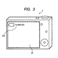
- Fig. 3 shows a diagram depicting an exemplary indication of the remaining amount of the battery in the digital camera.
- the LCD 23 is disposed for aligning the angle of view and reproducing images. Then, on the screen of the LCD 23, a remaining amount indication image 23a is displayed which indicates the remaining amount of the battery by OSD (On Screen Display), for example.
- OSD On Screen Display
- the remaining amount of the battery is displayed as a remaining usable time
- the remaining amount indication image 23a the remaining time is displayed as numerals in units of minutes, for example.
- the remaining amount indication image 23a may be displayed on the electronic view finder.
- the remaining amount may be displayed on a display part different from the display for image display.
- Fig. 4 shows a block diagram depicting the function of indicating the remaining amount of the battery in the battery protection circuit and the digital camera.
- the digital camera 2 has a remaining amount computing part 211 and a display processing part 212 as the function of indicating the remaining amount of the battery.
- the function of these parts is implemented by the microcontroller 21.
- the battery protection circuit 12 has a charge and discharge count measuring part 131, a decay rate output part 132, a current summing part 133, and a summed value correcting part 134 as the function of indicating the remaining amount of the battery.
- the functions of these parts are implemented by the microcontroller 110.
- the remaining amount computing part 211 of the digital camera 2 computes the remaining amount of the battery as a remaining usable time in accordance with the following equation:
- the remaining amount of the battery ( minute ) ⁇ ( the summed value of current of the moment [ mAh ] ⁇ 1 - decayrate ) / the summed value of current in full charge [ mAh ] ⁇ ⁇ the shooting time per 1.0 W [ minute ⁇ W ] / the power consuption [ W ]
- the summed value of current of the moment is the summed value of the charge and discharge current in the battery cell 11.
- the decay rate is an exponent that expresses the degree of decay of the battery cell 11, taking a value from 0 to 1.
- the battery cell 11 indicates that the battery cell 11 is a new one with no decay when the decay rate is 0, it indicates that the battery cell 11 is more decayed as the decay rate is larger, and it indicates that the battery cell 11 is most decayed and charge and discharge cannot be done at all when the decay rate is 1.
- the decay rate shows the rate of decreasing the capacity in accordance with the number of times of charges and discharges in the battery cell 11.
- the summed value of current of the moment and the decay rate are received from the battery pack 1 side through the control terminal 2c.
- the other parameters are the values decided depending on the specifications of the digital camera 2 itself, which are stored in advance in a non-volatile memory not shown in the drawing in the digital camera 2, and read and used when the remaining amount is computed.
- the display processing part 212 generates the remaining amount indication image 23a described above based on the remaining amount of the battery computed by the remaining amount computing part 211, combines it on an image to be displayed on the LCD 23, and supplies the signals of the combined image to the LCD 23.
- the remaining amount indication image 23a which indicates the computed remaining amount of the battery (time information) is displayed on the LCD 23.
- the charge and discharge count measuring part 131 detects the charge current to the battery cell 11 based on the voltage at both ends of the resistor R1, and counts the number of times of charges and discharges in the battery cell 11 on the basis of the summed value of current.
- the decay rate output part 132 computes the decay rate based on the count value of the number of times of charge and discharge, and outputs it to the remaining amount computing part 211 of the digital camera 2.
- the current summing part 133 detects the charge current and the discharge current based on the voltage at both ends of the resistor R1, and sums the current values.
- the summed value correcting part 134 corrects the summed value by the current summing part 133 in accordance with the cell voltage, and outputs it to the remaining amount computing part 211 of the digital camera 2.
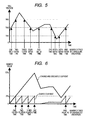
- Fig. 5 shows a diagram illustrative of the scheme of measuring the number of times of charges and discharges before for reference purposes.
- the decay rate is an exponent that expresses the degree of decay of the battery cell 11, and the chargeable and dischargeable capacity of the battery cell 11 is proportional to the value (1 - the decay rate). Since the decay rate becomes higher as the number of times of charges and discharges of the battery cell 11 is larger, in order to determine the decay rate, the number of times of charges and discharges of the battery cell 11 is measured by the charge and discharge count measuring part 131.
- the number of times of charges and discharges basically indicates the number of times of operation that the state of the cell voltage is first 0, turned to full charge, and returned to the voltage 0.
- the number of times of charges and discharges like this has been measured based on the conditions of increase and decrease in the cell voltage.
- Fig. 5 shows exemplary changes in the cell voltage.
- a plurality of thresholds is defined to the cell voltage (here, Vth1 to Vth3).
- the number of times of charges and discharges is counted.
- an amount of counts for one time is set finer in accordance with the number of steps of thresholds.
- Fig. 6 shows a diagram illustrative of a scheme of measuring the number of times of charges and discharges according to the embodiment.
- the charge and discharge count measuring part 131 counts the number of times of charges and discharges based on the summed value of current of the battery cell 11.
- this scheme it is characterized in that the number of times of charges and discharges is counted based on the value that sums only the current (charge current) when charged.
- Fig. 6 changes in the summed value of the charge and discharge current in association with charge and discharge operations are depicted by solid lines, and the summed value of the charge current at this time is depicted by doted lines.
- the threshold of the summed value of the charge current that counts the number of times of charges and discharges is set to 25% of the summed value of the charge current in full charge as an example. On this account, a count is made for every one-fourth time so that four counts are made and then the number of times of charges and discharges is one time, which makes errors small.
- this scheme for example, even in the case in which the summed value is reset before reaching the threshold and the summed value is cleared, an advantage is produced that can prevent the summed value from greatly deviating.
- the charger is connected to continuously carry a larger current when the battery cell 11 is charged than when discharged.
- the resolution for summing can be reduced, and the memory size for holding the summed value can be made smaller as well.
- the memory area for holding the summed value can be a constant size.
- the threshold of the summed value of the charge current for counting the number of times of charges and discharges is made to a relatively large value such as 25%, the measuring accuracy of the number of times of charges and discharges can be maintained. Therefore, the memory size for holding the count value of the number of times of charges and discharges can be made smaller as well.
- the number of times of charges and discharges is counted every time when the summed value of the charge current reaches a constant value.
- the advantage of improving the measuring accuracy of the number of times of charges and discharges can be obtained as similar to the description above by such a scheme that counts are made at every fixed time period.
- Fig. 7 shows a diagram illustrative of another exemplary scheme of measuring the number of times of charge and discharge.
- the charge and discharge count measuring part 131 computes the added value of the number of times of charges and discharges based on the summed value of the charge current at every fixed time period t.
- the added value is computed by dividing the summed value of the charge current at a fixed time period t by the summed value of current in full charge, and the value that the computed added value is added to the number of times of charges and discharges computed at this point in time is outputted to the decay rate output part 132.
- the measuring scheme it is sufficient to perform the computation of the number of times of charges and discharges in matching with the timing of outputting the decay rate by the decay rate output part 132. Therefore, the number of computations for the number of times of charges and discharges can be reduced, and there is a merit of easy control.
- LSB Location Significant Bit
- the decay rate output part 132 outputs the decay rate based on the measured result.
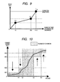
- the decay rate has been computed by a simple linear correction as shown in Fig. 8 .
- Fig. 8 shows a diagram illustrative of a scheme of computing the decay rate before for reference purposes.
- a linear line shown in Fig. 8 is used to convert the number of times of charges and discharges into the decay rate.
- the decay rate at the time that charges and discharges are repeated for 32 times as an example in advance, and the linear line created based on the measured result is shown. Therefore, suppose the decay rate is 0.1 when the number of times of charges and discharges is 32 times, the decay rate is computed as 0.2 when the number of times of charges and discharges is 64 times.
- the number of times of charges and discharges is split into a plurality of steps based on such a linear line, and the number of times is converted into the decay rate at each step.
- the relation between the number of times of charges and discharges and the decay rate does not take a linear line, the errors of the decay rate are large. On this account, the remaining amount of the battery can not be indicated accurately.
- Fig. 9 shows a graph for use in computing the decay rate in the embodiment.
- the decay rate is greatly increased, after that, the increase rate becomes gentle, and then the increase rate is again great after a certain number of times is exceeded.
- some of lithium ion secondary batteries have such characteristics that the decay rate is suddenly increased in the range of the number of times of charges and discharges from zero to about ten, the decay rate is increased gently in the range of the number of times of charges and discharges from about 10 to about 300, and the decay rate is again suddenly increased after the number of times of charges and discharges exceeds about 300.
- points of change C1 and C2 are set at which the slope of an increase in the decay rate changes, line interpolation is applied to connect the points of change, and the generated graph is used to convert the number of times of charges and discharges into the decay rate.
- the point of change C1 is set to the position at which the number of times of charges and discharges is ten
- the point of change C2 is set at the position at which the number of times of charges and discharges is 300.
- an end point of correction E in Fig. 9 is set on the conversion line when the number of times of charges and discharges is greater than 300, which shows the limit of the number of times of charges and discharges on specifications. It is sufficient that the points of change and the end point of correction are set at the positions corresponding to the characteristics of the battery cell 11.
- the graph described above is used to convert the number of times of charges and discharges into the decay rate, whereby the computation error of the decay rate can be deceased. Accordingly, with the combined use of the scheme of measuring the number of times of charge and discharge described above, a more accurate decay rate can be outputted to the remaining amount computing part 211 of the digital camera 2, and the remaining amount of the battery can be more accurately computed and indicated.
- the current summing part 133 sums the charge and discharge current of the battery cell 11.
- the current summation is basically performed in such a way that when the charge current is detected, the magnitude of current is added, whereas the discharge current is detected, the magnitude of current is subtracted. In this manner, it is known that since the summed value of current is computed by repeating summations and subtractions, errors tend to occur, and the errors are greater over time to degrade the computing accuracy.
- this is one of causes of occurrence of errors that a slight discharge current due to natural discharge cannot be detected in the case in which neither a discharge load nor a charger is connected to the battery pack 1. Then, it has been considered from before that the summed value of current is corrected.
- Fig. 10 shows a diagram illustrative of a scheme of correcting the summed value of current before for reference purposes. It is known that there is a certain relation between the summed value of the charge and discharge current and the voltage of the battery cell 11.
- a curve shown in a graph in Fig. 10 depicts the relation between the voltage and the summed value of the charge and discharge current when the electrode terminal of the battery cell 11 is opened based on the characteristics.
- Such a curve is used as a correction curve to approximate the summed value of current detected from the charge and discharge current to the summed value of current on the correction curve in accordance with the voltage of the battery cell 11 at this time, whereby the errors of the summed value of current can be reduced.
- OCV Open Circuit Voltage
- a plurality of steps is set for the voltage of the battery cell 11 and the summed value of current.
- four steps V1 to V4 are set for the voltage, and four steps AC1 to AC4 are set for the summed value of current as well.
- the area including the correction curve is defined as the area for permitting errors (the tolerance for errors).
- the summed value is included in the tolerance for errors corresponding to the voltage of the battery cell 11 at this time, the summed value is not corrected and outputted as it is.
- the summed value is corrected to the value on the border of the tolerance for errors.
- the correcting scheme like this has a smaller number of split steps, the scheme can be performed by relatively simple processing, and the power consumption of the microcontroller for performing the scheme is small as well.
- the correcting accuracy is high, and it is demanded to perform more highly accurate correction.
- this demand is increasing in association with a smaller power consumption of the microcontroller for correction.
- Fig. 11 shows a diagram illustrative of a scheme of correcting the summed value of charge and discharge current according to the embodiment.
- correction points greater than before are set on the same correction curve as that described above (in Fig. 11 , 16 points, for example), and the individual correction points are connected by a linear line to generate an approximated graph. Then, around the graph, a predetermined range is set to the tolerance for errors by ⁇ 0.4%, for example.
- the summed value correcting part 134 of the battery protection circuit 12 does not correct the summed value, and outputs it as it is.
- the summed value is corrected to the upper limit value of the tolerance for errors, whereas in the case in which the summed value is below the lower limit of the tolerance for errors, the summed value is corrected to the lower limit value of the tolerance for errors.
- the summed value correcting part 134 performs the correction process for every fixed time period (for example, every one hour) during the time from the point in time at which charge is completed and the charger is removed to the point in time at which the electrode terminal is in the open state.
- the summed value correcting part 134 reads the summed value of the charge and discharge current detected by the current summing part 133 and the detected value of the voltage of the battery cell 11 for every fixed time period to perform the correction process, and temporarily stores the corrected summed value of current in a memory, not shown.
- the summed value correcting part 134 receives a request for outputting the summed value of current from the remaining amount computing part 211, it outputs the stored summed value of current after corrected.
- the correction process for the summed value described in Fig. 11 may be applied to the summation process of the charge current in the charge and discharge count measuring part 131.
- the summed value is corrected to the upper limit or the lower limit of the tolerance for errors in the case in which the summed value of the charge current is not included in the tolerance for errors corresponding to the voltage of the battery cell 11 at this time based on the same tolerance for errors as that of the summed value correcting part 134. It is sufficient that the correction process like this is performed at the same timing as the summed value correcting part 134.
- the measurement errors of the number of times of charges and discharges can be reduced as well.
- the accuracy for both of the summed value of current and the decay rate which are parameters necessary to compute the remaining amount of the battery can be improved. Therefore, the remaining amount of the battery can be more accurately computed, and the usable remaining time and others can be indicated and transmitted to a user.
- the number of times of charges and discharges of the secondary battery is measured based on the summed value of the charge current of the secondary battery, and the decay rate is computed based on the measured result. Therefore, the accuracy of the decay rate can be more improved than the case in which the number of times of charges and discharges is measured based on the voltage and the charge and discharge current of the secondary battery. Particularly, in the case in which charges and discharges are repeated in the range of a smaller voltage difference in the secondary battery, the measurement errors of the number of times of charges and discharges can be suppressed significantly, and consequently, the computing accuracy of the decay rate can be improved. Accordingly, the remaining amount of the secondary battery is detected based on the decay rate thus computed, whereby the remaining amount can be detected more accurately.
Abstract
A battery pack has a charge and discharge count measuring part (131) configured to measure the number of times of charges and discharges of a secondary battery based on the summed value of the charge current for the secondary battery, and a decay rate output part (132) configured to compute a decay rate that indicates a degree of decay of the secondary battery based on the number of times of charges and discharges measured by the charge and discharge count measuring part (131) and to output it to a device being a discharge load. For example, the charge and discharge count measuring part (131) repeatedly sums the detected values of the charge current to a predetermined threshold, and counts up the number of times of charges and discharges every time when the summed value reaches the threshold. Accordingly, even though charges and discharges are repeated at finer steps in a relatively narrow voltage range, the number of times of charges and discharges can be counted accurately, and the computing accuracy of the decay rate is improved. In the battery pack in which the secondary battery is accommodated, parameters for detecting the remaining amount of the battery are detected more accurately.
Description
- The present invention relates to a battery pack which accommodates a secondary battery and a processing circuit in one piece therein, the processing circuit performs a predetermined process based on various detected values from the secondary battery, an electronic appliance which receives the supply of power from the secondary battery inside the battery pack to operate, and a method of detecting a remaining amount of a battery in such an electronic appliance.
- In recent years, for example, portable electronic appliances such as a digital video camera are increasing rapidly, and a great importance is placed on the performance of a secondary battery mounted on these electronic appliances. As one of these secondary batteries, there is a so-called lithium ion type battery.
- In addition, in such portable electronic appliances described above using a secondary battery as a power source, many of them have the function of indicating the remaining amount of the battery mounted thereon. Particularly, in a lithium ion secondary battery, since it has properties that the voltage of the battery cell drops gently and linearly except right after the start of discharge and right before the end of discharge, the remaining amount of the battery can be relatively, accurately predicted and indicated.
- However, although the secondary battery including the lithium ion type has the capacity that is decided for every battery cell, it has characteristics that the capacity changes depending on the temperature for use. For example, when the battery is used at low temperature, the internal impedance of the battery cell becomes high. Thus, the voltage drop becomes large when it is intended to carry current at the same current value, and the capacity of the battery cell is reduced. In addition, also in the case in which the number of times of charges and discharges is increased because of continuous use, it has characteristics that the capacity is reduced. This is because the repetition of charge and discharge causes the battery cell to be deteriorated, and the usable capacity is reduced.
- Then, in a secondary battery before, such functions are provided that the temperature of the battery cell and the number of times of charge and discharge are detected, and the remaining amount of the battery is corrected in accordance with the detected values. For example, there is a secondary battery in which the correction value of the remaining amount corresponding to the detected value of the temperature of the battery cell is set to each of the numbers of times of charge and discharge, and the computation error of the remaining amount of the battery is reduced (for example, see
JP-A-2005-147815 Fig. 1 )). In addition, in the secondary battery before, it is general that the number of times of charges is detected when the voltage of the battery cell rises and drops around a predetermined threshold. - Moreover, today, in order to more accurately predict the capacity of a battery, such battery packs are commercially available that detection circuits for the voltage and current of the battery cell and microcontrollers for various correction processes are accommodated in the same package as a battery cell. Such battery packs have functions that communicate with a device to be a discharge load and output various detected values thereinside to the device, in which the device having received these detected values computes the remaining amount of the battery as a usable time and indicates it. For example, inside the battery pack, the summed value of current in the battery cell and the decay rate of the capacity based on the temperature and on the number of times of charges and discharges and others described above are detected, in which these values are received on the device side and the remaining amount of the battery can be computed accurately.
- As described above, in order to accurately compute the remaining amount of the battery, it is necessary to accurately detect the summed value of current in the battery cell and the decay rate based on the temperature and on the number of times of charge and discharge. However, as discussed above, in the scheme in which the number of times of charges and discharges is detected based on the comparison of the voltage change in the battery cell when charged and discharged with the threshold, in the case in which charges and discharges are repeated within a relatively narrow voltage range in which the threshold does not pass, such an event can occur that the number of times of charges and discharges is not counted. In this case, it cannot be said that the number of times of charges and discharges is accurately counted, causing a problem that the decay rate cannot be detected accurately. In addition, it is demanded for the process of converting the number of times of charges and discharges into the decay rate that more detailed processes are performed close to realities.
- The invention has been made in view of these points. An object is to provide a battery pack which can more accurately detect parameters for detecting the remaining amount of the battery.
In addition, another object of the invention is to provide an electronic appliance which can more accurately detect the remaining amount of the battery. - Moreover, still another object of the invention is to provide a method of detecting a remaining amount of a battery which can more accurately detect the remaining amount of the battery.
- In the invention, in order to solve the problems, a battery pack is provided in which a processing circuit which performs a predetermined process based on various detected values from a secondary battery is accommodated in one piece with the secondary battery, the battery pack characterized by comprising: a charge current summing part configured to sum a detected value of charge current for the secondary battery; a charge and discharge count measuring part configured to measure the number of times of charges and discharges of the secondary battery based on the summed value of the charge current by the charge current summing part; a decay rate computing part configured to compute a decay rate that indicates a degree of decay of the secondary battery based on the number of times of charges and discharges measured by the charge and discharge count measuring part; and a communicating part configured to output the decay rate computed by the decay rate computing part to an external device that is a discharge load of the secondary battery.
- In the battery pack like this, the decay rate that indicates a degree of decay of the secondary battery is computed as one of parameters for computing the remaining amount of the secondary battery in an external device to be a discharge load. The charge current summing part sums the detected values of the charge current for the secondary battery. The charge and discharge count measuring part measures the number of times of charges and discharges of the secondary battery based on the summed value of the charge current by the charge current summing part. The decay rate computing part computes the decay rate that indicates the degree of decay of the secondary battery based on the number of times of charges and discharges measured by the charge and discharge count measuring part. The communicating part outputs the decay rate computed by the decay rate computing part to the external device.
-
-
Fig. 1 shows a diagram depicting the configuration of the essential part of a digital camera and a battery pack according to an embodiment of the invention; -
Fig. 2 shows a diagram depicting the hardware configuration of a battery protection circuit; -
Fig. 3 shows a diagram depicting an exemplary indication of the remaining amount of the battery in the digital camera; -
Fig. 4 shows a block diagram depicting the battery protection circuit and the function of indicating the remaining amount of the battery in the digital camera; -
Fig. 5 shows a diagram illustrative of a scheme of measuring the number of times of charges and discharges before; -
Fig. 6 shows a diagram illustrative of a scheme of measuring the number of times of charges and discharges according to the embodiment; -
Fig. 7 shows a diagram illustrative of another exemplary scheme of measuring the number of times of charge and discharge; -
Fig. 8 shows a diagram illustrative of a scheme of computing the decay rate before; -
Fig. 9 shows a graph used for computing a decay rate according to the embodiment; -
Fig. 10 shows a diagram illustrative of a scheme of correcting the summed value of current before; and -
Fig. 11 shows a diagram illustrative of a scheme of correcting the summed value of charge and discharge current according to the embodiment. - Hereinafter, an embodiment of the invention will be described in detail with reference to the drawings. In addition, in the embodiment below, a digital camera is taken as an example and described which operates using a secondary battery as a power source.
Fig. 1 shows a diagram depicting the configuration of the essential part of a digital camera and a battery pack according to the embodiment of the invention. - A
battery pack 1 shown inFig. 1 accommodates in a package in one piece abattery cell 11 which is formed of a secondary battery, and abattery protection circuit 12 which mainly implements the function of protecting thebattery cell 11 against abnormal states. In addition, adigital camera 2 is an apparatus that images an image by a solid state imaging device (not shown) and records the image as digital data on a recording medium (not shown) and that operates with the supply of power from thebattery pack 1. - In the
battery pack 1, a positive terminal 11a and anegative terminal 11b of thebattery cell 11 are connected to apositive terminal 12a on the cell side and anegative terminal 12b on the cell side of thebattery protection circuit 12, respectively, by welding, for example. In addition, an external positive terminal 12c and an external negative terminal 12d of thebattery protection circuit 12 are a feed terminal that supplies electric power to thedigital camera 2, and also serves as a terminal that receives power supply from an external charger. Moreover, thebattery protection circuit 12 is also provided with acontrol terminal 12e which communicates with thedigital camera 2. - The
battery protection circuit 12 has amicrocontroller 110, a charge control FET (Field Effect Transistor) 121, adischarge control FET 122, and a current detecting resistor R1. In thebattery protection circuit 12, themicrocontroller 110 controls the operations of thecharge control FET 121 and thedischarge control FET 122 in accordance with the voltage and the charge and discharge current of thebattery cell 11, whereby the function of protecting thebattery cell 11 is implemented when abnormal conditions occur. Along with this, such a function is also provided that parameters are computed in thedigital camera 2 that are necessary to accurately indicate the remaining capacity of thebattery cell 11 and the parameters are sent to thedigital camera 2 through thecontrol terminal 12e. - In addition, for the
battery cell 11, for example, a lithium ion type secondary battery can be used. Such a secondary battery is used that has discharge characteristics which discharge voltage relatively, gently and linearly drops like the lithium ion secondary battery, whereby the remaining amount of the battery is highly accurately detected on thedigital camera 2 side, and the remaining amount of the battery can be indicated as a remaining usable time, for example. - On the other hand, in the
digital camera 2, the external positive terminal 12c and the external negative terminal 12d of thebattery pack 1 are connected topower source terminals battery pack 1. In addition, thedigital camera 2 has acontrol terminal 2c which communicates with thebattery pack 1, and can receive parameters necessary to indicate the remaining amount of the battery from thebattery protection circuit 12. - The
digital camera 2 has amicrocontroller 21 which generally controls the overall apparatus, aregulator 22 which stabilizes the applied voltage from the power source terminal 2a to a predetermined voltage and supplies it inside the apparatus, and a display which shows thereon a through image of a camera for aligning the angle of view, a reproduced image based on image data recorded on the recording medium, the remaining amount of the battery, and so on (here, it is an LCD (Liquid Crystal Display) 23 as an example). -
Fig. 2 shows a diagram depicting the hardware configuration of the battery protection circuit.
As shown inFig. 2 , themicrocontroller 110 inside thebattery protection circuit 12 has a CPU (Central Processing Unit) 111, adriver 112, acommunication interface circuit 113, and an A/D converter circuit 114. - The CPU 111 executes a program stored in a non-volatile memory, not shown, whereby it performs various computations and controls for implementing the function of protecting the
battery cell 11 described above, and the function of processing the computations of the remaining amount of the battery. Under control done by the CPU 111, thedriver 112 outputs the gate voltages of thecharge control FET 121 and thedischarge control FET 122, and drives the individual FETs. Thecommunication interface circuit 113 is an interface that performs serial communications, for example, which is connected to thedigital camera 2 through thecontrol terminal 12e and communicates between thedigital camera 2 and the CPU 111 in accordance with a predetermined format. - The A/D converter circuit 114 detects the voltage on both ends of the resistor R1 which is inserted between the
positive terminal 12a on the cell side and thecharge control FET 121 and the voltage on the external positive terminal 12c, converts them into digital signals, and supplies them to the CPU 111. Accordingly, the CPU 111 can detect the presence of the start of charge based on the voltage of the battery cell 11 (hereinafter, referred to as cell voltage) and the voltage of the external positive terminal 12c, and the magnitude of the charge and discharge current any time. - The
charge control FET 121 and thedischarge control FET 122 are formed of a MOSFET (Metal Oxide Semiconductor FET) in which a diode is equivalently incorporated between the source and the drain, and the FETs function as a protection switch when thebattery cell 11 is charged and discharged under control done by themicrocontroller 110. In other words, thecharge control FET 121 can selectively block charge current to thebattery cell 11 and can charge from the charger to thebattery cell 11 when conducted. In addition, thedischarge control FET 122 can selectively block the discharge current of thebattery cell 11, discharge thebattery cell 11 when conducted, and then supply power source to thedigital camera 2. Then, the CPU 111 controls these FETs in accordance with the cell voltage, the charge and discharge current, and the detection of the presence of the start of charge, whereby the function of protecting thebattery cell 11 is implemented. - In addition, although not shown in the drawings, the
microcontroller 21 provided in thedigital camera 2 is formed of a CPU and a memory, in which a program stored in the memory is executed by the CPU to implement various control functions inside the apparatus and the computation function of indicating the remaining amount of the battery and others. - Next, the function of indicating the remaining amount of the battery which is implemented in the
battery pack 1 and thedigital camera 2 will be described in detail. First,Fig. 3 shows a diagram depicting an exemplary indication of the remaining amount of the battery in the digital camera. - In the
digital camera 2, as shown inFig. 3 , on the back side opposite to the imaging side on which the lens and others are provided, theLCD 23 is disposed for aligning the angle of view and reproducing images. Then, on the screen of theLCD 23, a remainingamount indication image 23a is displayed which indicates the remaining amount of the battery by OSD (On Screen Display), for example. In the embodiment, the remaining amount of the battery is displayed as a remaining usable time, and on the remainingamount indication image 23a, the remaining time is displayed as numerals in units of minutes, for example. Moreover, in addition to this, for example, in the case in which an electronic view finder formed of LCD is provided, the remainingamount indication image 23a may be displayed on the electronic view finder. In addition, the remaining amount may be displayed on a display part different from the display for image display. -
Fig. 4 shows a block diagram depicting the function of indicating the remaining amount of the battery in the battery protection circuit and the digital camera.
Thedigital camera 2 has a remainingamount computing part 211 and adisplay processing part 212 as the function of indicating the remaining amount of the battery. The function of these parts is implemented by themicrocontroller 21. In addition, thebattery protection circuit 12 has a charge and dischargecount measuring part 131, a decayrate output part 132, a current summingpart 133, and a summedvalue correcting part 134 as the function of indicating the remaining amount of the battery. The functions of these parts are implemented by themicrocontroller 110. - The remaining
amount computing part 211 of thedigital camera 2 computes the remaining amount of the battery as a remaining usable time in accordance with the following equation:
Here, the summed value of current of the moment is the summed value of the charge and discharge current in thebattery cell 11. In addition, the decay rate is an exponent that expresses the degree of decay of thebattery cell 11, taking a value from 0 to 1. In other words, it indicates that thebattery cell 11 is a new one with no decay when the decay rate is 0, it indicates that thebattery cell 11 is more decayed as the decay rate is larger, and it indicates that thebattery cell 11 is most decayed and charge and discharge cannot be done at all when the decay rate is 1. Particularly in the embodiment, in view of the fact that the battery capacity is more reduced as the number of times of charges and discharges is larger, it is considered that the decay rate shows the rate of decreasing the capacity in accordance with the number of times of charges and discharges in thebattery cell 11. - The summed value of current of the moment and the decay rate are received from the
battery pack 1 side through thecontrol terminal 2c. In addition, the other parameters are the values decided depending on the specifications of thedigital camera 2 itself, which are stored in advance in a non-volatile memory not shown in the drawing in thedigital camera 2, and read and used when the remaining amount is computed. - The
display processing part 212 generates the remainingamount indication image 23a described above based on the remaining amount of the battery computed by the remainingamount computing part 211, combines it on an image to be displayed on theLCD 23, and supplies the signals of the combined image to theLCD 23. Thus, the remainingamount indication image 23a which indicates the computed remaining amount of the battery (time information) is displayed on theLCD 23. - On the other hand, in the
battery protection circuit 12, the charge and dischargecount measuring part 131 detects the charge current to thebattery cell 11 based on the voltage at both ends of the resistor R1, and counts the number of times of charges and discharges in thebattery cell 11 on the basis of the summed value of current. The decayrate output part 132 computes the decay rate based on the count value of the number of times of charge and discharge, and outputs it to the remainingamount computing part 211 of thedigital camera 2. The current summingpart 133 detects the charge current and the discharge current based on the voltage at both ends of the resistor R1, and sums the current values. The summedvalue correcting part 134 corrects the summed value by the current summingpart 133 in accordance with the cell voltage, and outputs it to the remainingamount computing part 211 of thedigital camera 2. - Next, the individual functions provided in the
battery protection circuit 12 will be described. First, a scheme of measuring the number of times of charges and discharges for determining the decay rate will be described.Fig. 5 shows a diagram illustrative of the scheme of measuring the number of times of charges and discharges before for reference purposes. - As described above, the decay rate is an exponent that expresses the degree of decay of the
battery cell 11, and the chargeable and dischargeable capacity of thebattery cell 11 is proportional to the value (1 - the decay rate). Since the decay rate becomes higher as the number of times of charges and discharges of thebattery cell 11 is larger, in order to determine the decay rate, the number of times of charges and discharges of thebattery cell 11 is measured by the charge and dischargecount measuring part 131. Here, the number of times of charges and discharges basically indicates the number of times of operation that the state of the cell voltage is first 0, turned to full charge, and returned to thevoltage 0. Heretofore, the number of times of charges and discharges like this has been measured based on the conditions of increase and decrease in the cell voltage. -
Fig. 5 shows exemplary changes in the cell voltage. As shown inFig. 5 , in the manner before, a plurality of thresholds is defined to the cell voltage (here, Vth1 to Vth3). In the cases in which the cell voltage rises as passing through the threshold and the cell voltage drops as passing through the threshold, the number of times of charges and discharges is counted. However, an amount of counts for one time is set finer in accordance with the number of steps of thresholds. In this example, since three steps of thresholds are defined, it is assumed as a single charge that the state of the cell voltage is first 0, turned to full charge, and returned to thevoltage 0, in which every time when the cell voltage is changed as passing through a single threshold, the number of times of charges and discharges is counted for one-sixth time each. - However, according to this scheme, in the case in which charges and discharges are repeated in a relatively narrow voltage range in which the threshold is not passed, the number of times of charges and discharges is not counted. In other words, when charges and discharges are repeated in the range of the same cell voltage, although it can be considered that the progress of decay is almost the same, the number of times of charges and discharges to be counted is varied depending on whether the range of changes in the cell voltage includes the threshold. As described above, in the scheme of measuring the number of times of charges and discharges before, it cannot be said that the number of times of charges and discharges is accurately counted, causing a problem that there is the case in which the decay rate cannot be accurately detected to deteriorate the computing accuracy of the remaining amount of the battery.
-
Fig. 6 shows a diagram illustrative of a scheme of measuring the number of times of charges and discharges according to the embodiment.
In contrast to the scheme before described above, the charge and dischargecount measuring part 131 according to the embodiment counts the number of times of charges and discharges based on the summed value of current of thebattery cell 11. In addition to this, according to this scheme, it is characterized in that the number of times of charges and discharges is counted based on the value that sums only the current (charge current) when charged. - In
Fig. 6 , changes in the summed value of the charge and discharge current in association with charge and discharge operations are depicted by solid lines, and the summed value of the charge current at this time is depicted by doted lines. In addition, the threshold of the summed value of the charge current that counts the number of times of charges and discharges is set to 25% of the summed value of the charge current in full charge as an example. On this account, a count is made for every one-fourth time so that four counts are made and then the number of times of charges and discharges is one time, which makes errors small. In addition, with this scheme, for example, even in the case in which the summed value is reset before reaching the threshold and the summed value is cleared, an advantage is produced that can prevent the summed value from greatly deviating. - With this scheme, even though charges and discharges are repeated at finer steps in a relatively narrow voltage range, the number of times of charges and discharges can be counted accurately. Particularly, counts are made based on the summed value of the charge current, not on the discharge current, whereby the measuring accuracy of the number of times of charges and discharges can be improved. For example, a slight discharge current is sometimes carried due to natural discharge even though the external positive terminal 12c and the external negative terminal 12d of the
battery pack 1 are in the open state. However, a slight current might not be detected by summing the discharge current. On this account, the number of times of charges and discharges is counted based on the discharge current, which causes great errors of the number of times of charge and discharge. Therefore, the number of times of charges and discharges is measured based on the summed value of the charge current to improve the measuring accuracy. - In addition, when the slight current is allowed to be detected in the case in which the discharge current is summed, it is necessary to increase the resolution of the summed value of current, and then the memory size for holding the summed value becomes large. In contrast to this, the charger is connected to continuously carry a larger current when the
battery cell 11 is charged than when discharged. Thus, in the case of summing the charge current, the resolution for summing can be reduced, and the memory size for holding the summed value can be made smaller as well. In addition, since the summed value of the charge current does not exceed a constant value (25% in the example above), the memory area for holding the summed value can be a constant size. - In addition, even though the threshold of the summed value of the charge current for counting the number of times of charges and discharges is made to a relatively large value such as 25%, the measuring accuracy of the number of times of charges and discharges can be maintained. Therefore, the memory size for holding the count value of the number of times of charges and discharges can be made smaller as well.
- Now, according to the scheme above, the number of times of charges and discharges is counted every time when the summed value of the charge current reaches a constant value. However, in addition to this, for example, as described below, the advantage of improving the measuring accuracy of the number of times of charges and discharges can be obtained as similar to the description above by such a scheme that counts are made at every fixed time period.
-
Fig. 7 shows a diagram illustrative of another exemplary scheme of measuring the number of times of charge and discharge.
In this measuring scheme, as shown inFig. 7 , the charge and dischargecount measuring part 131 computes the added value of the number of times of charges and discharges based on the summed value of the charge current at every fixed time period t. The added value is computed by dividing the summed value of the charge current at a fixed time period t by the summed value of current in full charge, and the value that the computed added value is added to the number of times of charges and discharges computed at this point in time is outputted to the decayrate output part 132. - In the measuring scheme, it is sufficient to perform the computation of the number of times of charges and discharges in matching with the timing of outputting the decay rate by the decay
rate output part 132. Therefore, the number of computations for the number of times of charges and discharges can be reduced, and there is a merit of easy control. On the other hand, it is necessary to reduce the value of the number of times that corresponds to LSB (Least Significant Bit) in binary data indicating the number of times of charge and discharge, and the memory size for holding the number of times of charges and discharges is greater. For example, the measuring accuracy as similar to the example inFig. 6 cannot be obtained unless otherwise the number of times corresponding to LSB is not made smaller than one-fourth time. In addition, in order to allow the detection of the maximum charge current carried at a fixed time period t when quick charge, since it is necessary to decide the size of a buffer for storing the summed value of current, the buffer size is made larger as well. Therefore, in consideration of the merit and demerit above, it is sufficient to select a suited measuring scheme inFig. 6 orFig. 7 . - As described above, the number of times of charges and discharges is measured, and then the decay
rate output part 132 outputs the decay rate based on the measured result. In the manner before, the decay rate has been computed by a simple linear correction as shown inFig. 8 . -
Fig. 8 shows a diagram illustrative of a scheme of computing the decay rate before for reference purposes.
In the manner before, a linear line shown inFig. 8 is used to convert the number of times of charges and discharges into the decay rate. InFig. 8 , the decay rate at the time that charges and discharges are repeated for 32 times as an example in advance, and the linear line created based on the measured result is shown. Therefore, suppose the decay rate is 0.1 when the number of times of charges and discharges is 32 times, the decay rate is computed as 0.2 when the number of times of charges and discharges is 64 times. Alternatively, in the manner before, the number of times of charges and discharges is split into a plurality of steps based on such a linear line, and the number of times is converted into the decay rate at each step. However, in practice, since the relation between the number of times of charges and discharges and the decay rate does not take a linear line, the errors of the decay rate are large. On this account, the remaining amount of the battery can not be indicated accurately. -
Fig. 9 shows a graph for use in computing the decay rate in the embodiment.
Generally, in the secondary battery, it is known that in the case in which the number of times of charges and discharges is small, the decay rate is greatly increased, after that, the increase rate becomes gentle, and then the increase rate is again great after a certain number of times is exceeded. For example, some of lithium ion secondary batteries have such characteristics that the decay rate is suddenly increased in the range of the number of times of charges and discharges from zero to about ten, the decay rate is increased gently in the range of the number of times of charges and discharges from about 10 to about 300, and the decay rate is again suddenly increased after the number of times of charges and discharges exceeds about 300. - Then, in the embodiment, as shown in
Fig. 9 , points of change C1 and C2 are set at which the slope of an increase in the decay rate changes, line interpolation is applied to connect the points of change, and the generated graph is used to convert the number of times of charges and discharges into the decay rate. In the example shown inFig. 9 , the point of change C1 is set to the position at which the number of times of charges and discharges is ten, and the point of change C2 is set at the position at which the number of times of charges and discharges is 300. In addition, an end point of correction E inFig. 9 is set on the conversion line when the number of times of charges and discharges is greater than 300, which shows the limit of the number of times of charges and discharges on specifications. It is sufficient that the points of change and the end point of correction are set at the positions corresponding to the characteristics of thebattery cell 11. - The graph described above is used to convert the number of times of charges and discharges into the decay rate, whereby the computation error of the decay rate can be deceased. Accordingly, with the combined use of the scheme of measuring the number of times of charge and discharge described above, a more accurate decay rate can be outputted to the remaining
amount computing part 211 of thedigital camera 2, and the remaining amount of the battery can be more accurately computed and indicated. - Next, the scheme of computing the summed value of current to be outputted to the remaining
amount computing part 211 of thedigital camera 2 will be described. In thebattery protection circuit 12, the current summingpart 133 sums the charge and discharge current of thebattery cell 11. The current summation is basically performed in such a way that when the charge current is detected, the magnitude of current is added, whereas the discharge current is detected, the magnitude of current is subtracted. In this manner, it is known that since the summed value of current is computed by repeating summations and subtractions, errors tend to occur, and the errors are greater over time to degrade the computing accuracy. For example, as described above, this is one of causes of occurrence of errors that a slight discharge current due to natural discharge cannot be detected in the case in which neither a discharge load nor a charger is connected to thebattery pack 1. Then, it has been considered from before that the summed value of current is corrected. -
Fig. 10 shows a diagram illustrative of a scheme of correcting the summed value of current before for reference purposes.
It is known that there is a certain relation between the summed value of the charge and discharge current and the voltage of thebattery cell 11. A curve shown in a graph inFig. 10 depicts the relation between the voltage and the summed value of the charge and discharge current when the electrode terminal of thebattery cell 11 is opened based on the characteristics. Such a curve is used as a correction curve to approximate the summed value of current detected from the charge and discharge current to the summed value of current on the correction curve in accordance with the voltage of thebattery cell 11 at this time, whereby the errors of the summed value of current can be reduced. It is necessary that the correction like this is performed at the time when the electrode terminal of thebattery cell 11 is opened. In the manner before, the correction is performed only one time after charge is completed, in order to suppress power consumption. In addition, a correction using such a correction curve is called OCV (Open Circuit Voltage) correction. - However, in the manner before, there are a few number of battery packs that have the correction function of the summed value of current using the correction curve like this, and even the battery packs having the function only perform a simple correction at intervals of a few steps.
- For example, as shown in
Fig. 10 , a plurality of steps is set for the voltage of thebattery cell 11 and the summed value of current. InFig. 10 , four steps V1 to V4 are set for the voltage, and four steps AC1 to AC4 are set for the summed value of current as well. Then, in the areas on the graph generated by these steps, the area including the correction curve is defined as the area for permitting errors (the tolerance for errors). In the case in which when the summed value of the charge and discharge current is measured, the summed value is included in the tolerance for errors corresponding to the voltage of thebattery cell 11 at this time, the summed value is not corrected and outputted as it is. In addition, in the case in which the summed value is not included in the tolerance for errors, the summed value is corrected to the value on the border of the tolerance for errors. - For example, in the case in which the voltage of the
battery cell 11 is 0 or below V1, no correction is made if the measured summed value of current is equal to or below AC1, whereas the summed value of current is corrected to AC1 and outputted if the value is above AC1,. Alternatively, in the case in which the voltage of thebattery cell 11 is equal to V3 or below V4, no correction is made if the measured summed value of current is equal to or above AC3, whereas the summed value of current is corrected to AC3 and outputted if the value is below AC3. In addition, since the errors of the summed value of current relatively tend not to occur in the case in which the voltage of thebattery cell 11 exists in the intermediate area with respect to the maximum voltage, in the intermediate area like this (inFig. 10 , the area equal to V2 and below V3), the summed value of current is not corrected. - Since the correcting scheme like this has a smaller number of split steps, the scheme can be performed by relatively simple processing, and the power consumption of the microcontroller for performing the scheme is small as well. However, it cannot be said that the correcting accuracy is high, and it is demanded to perform more highly accurate correction. Particularly, in recent years, this demand is increasing in association with a smaller power consumption of the microcontroller for correction.
-
Fig. 11 shows a diagram illustrative of a scheme of correcting the summed value of charge and discharge current according to the embodiment.
As shown inFig. 11 , in the embodiment, correction points greater than before are set on the same correction curve as that described above (inFig. 11 , 16 points, for example), and the individual correction points are connected by a linear line to generate an approximated graph. Then, around the graph, a predetermined range is set to the tolerance for errors by ±0.4%, for example. - In the case in which the summed value is included in the tolerance for errors corresponding to the voltage of the
battery cell 11 at this time when the summed value of the charge and discharge current is measured based on the preset tolerance for errors, the summedvalue correcting part 134 of thebattery protection circuit 12 does not correct the summed value, and outputs it as it is. In addition, in the case in which the summed value is greater than the upper limit of the tolerance for errors, the summed value is corrected to the upper limit value of the tolerance for errors, whereas in the case in which the summed value is below the lower limit of the tolerance for errors, the summed value is corrected to the lower limit value of the tolerance for errors. - In addition, the summed
value correcting part 134 performs the correction process for every fixed time period (for example, every one hour) during the time from the point in time at which charge is completed and the charger is removed to the point in time at which the electrode terminal is in the open state. In other words, the summedvalue correcting part 134 reads the summed value of the charge and discharge current detected by the current summingpart 133 and the detected value of the voltage of thebattery cell 11 for every fixed time period to perform the correction process, and temporarily stores the corrected summed value of current in a memory, not shown. Then, after that, at the time when the discharge load (the digital camera 2) is connected and the summedvalue correcting part 134 receives a request for outputting the summed value of current from the remainingamount computing part 211, it outputs the stored summed value of current after corrected. Thus, errors of the summed value of current particularly caused by voltage drop due to natural discharge can be reliably reduced, and the computing accuracy of the remaining amount of the battery in the remainingamount computing part 211 can be improved. - In addition, the correction process for the summed value described in
Fig. 11 may be applied to the summation process of the charge current in the charge and dischargecount measuring part 131. In this case, the summed value is corrected to the upper limit or the lower limit of the tolerance for errors in the case in which the summed value of the charge current is not included in the tolerance for errors corresponding to the voltage of thebattery cell 11 at this time based on the same tolerance for errors as that of the summedvalue correcting part 134. It is sufficient that the correction process like this is performed at the same timing as the summedvalue correcting part 134. Thus, the measurement errors of the number of times of charges and discharges can be reduced as well. - As described above, in accordance with the
battery pack 1 according to the embodiment, the accuracy for both of the summed value of current and the decay rate which are parameters necessary to compute the remaining amount of the battery can be improved. Therefore, the remaining amount of the battery can be more accurately computed, and the usable remaining time and others can be indicated and transmitted to a user. - In accordance with the battery pack according to the invention, the number of times of charges and discharges of the secondary battery is measured based on the summed value of the charge current of the secondary battery, and the decay rate is computed based on the measured result. Therefore, the accuracy of the decay rate can be more improved than the case in which the number of times of charges and discharges is measured based on the voltage and the charge and discharge current of the secondary battery. Particularly, in the case in which charges and discharges are repeated in the range of a smaller voltage difference in the secondary battery, the measurement errors of the number of times of charges and discharges can be suppressed significantly, and consequently, the computing accuracy of the decay rate can be improved. Accordingly, the remaining amount of the secondary battery is detected based on the decay rate thus computed, whereby the remaining amount can be detected more accurately.
Claims (14)
- A battery pack in which a processing circuit which performs a predetermined process based on various detected values from a secondary battery is accommodated in one piece with the secondary battery, the battery pack characterized by comprising:a charge current summing part configured to sum a detected value of charge current for the secondary battery;a charge and discharge count measuring part configured to measure the number of times of charges and discharges of the secondary battery based on the summed value of the charge current by the charge current summing part;a decay rate computing part configured to compute a decay rate that indicates a degree of decay of the secondary battery based on the number of times of charges and discharges measured by the charge and discharge count measuring part; anda communicating part configured to output the decay rate computed by the decay rate computing part to an external device that is a discharge load of the secondary battery.
- The battery pack according to claim 1, characterized in that:the charge current summing part repeatedly sums the detected values of the charge current to a predetermined threshold, andthe charge and discharge count measuring part counts up the number of times of charges and discharges every time when the summed value of the charge current by the charge current summing part reaches the threshold.
- The battery pack according to claim 2, characterized in that the charge and discharge count measuring part adds the number of times of charges and discharges by a ratio of the threshold for the summed value of the charge current in full charge every time when the summed value of the charge current by the charge current summing part reaches the threshold.
- The battery pack according to claim 1, characterized in that:the charge current summing part sums a magnitude of the charge current for every fixed time period; andthe charge and discharge count measuring part decides the added value of the number of times of charges and discharges based on the summed value of the charge current for each of the fixed time periods from the charge current summing part, and adds the added value to the number of times of charges and discharges computed immediately before for output.
- The battery pack according to claim 4, characterized in that the charge and discharge count measuring part divides the summed value of the charge current for the fixed time period by the summed value of the charge current in full charge, whereby it decides the added value.
- The battery pack according to claim 4, characterized in that the decay rate computing part computes the decay rate for each of the fixed time periods.
- The battery pack according to claim 1, characterized in that the decay rate computing part associates in advance the number of times of charges and discharges with the decay rate by means of a graph having at least two points of change in a slope, and converts the number of times of charges and discharges measured by the charge and discharge count measuring part into the decay rate based on the graph.
- The battery pack according to claim 7, characterized in that in the graph, a slope of the decay rate in accordance with an increase in the number of times of charges and discharges is made smaller than that in therearound in an intermediate area except areas in which the number of times of charges and discharges is the minimum and the maximum.
- The battery pack according to claim 1, characterized by further comprising:a charge and discharge current summing part configured to sum a detected value of charge and discharge current of the secondary battery;a voltage detecting part configured to detect a voltage between a positive electrode and a negative electrode of the secondary battery; anda summed value correcting part configured to preset a tolerance for errors in which the summed value of charge and discharge current takes a fixed width around an approximated line that a curve associating voltage between a positive electrode and a negative electrode of the secondary battery when an electrode of the secondary battery is opened with the summed value of charge and discharge current by means of a graph, and to correct the summed value of charge and discharge current by the charge and discharge current summing part so as to be included in the tolerance for errors in accordance with a detected value of voltage at this time by the voltage detecting part,wherein the communicating part outputs the summed value of charge and discharge current corrected by the summed value correcting part to the external device together with the decay rate.
- The battery pack according to claim 9, characterized in that during the time for which the electrode of the secondary battery is opened after charge of the secondary battery is completed, the summed value correcting part corrects the summed value of charge and discharge current for every fixed time period.
- The battery pack according to claim 9, characterized in that the summed value correcting part corrects the summed value of charge and discharge current as well as the summed value of the charge current by the charge current summing part by means of a similar process, and supplies the corrected summed value of the charge current to the charge and discharge count measuring part.
- The battery pack according to claim 1, characterized by further comprising:a voltage detecting part configured to detect a voltage between a positive electrode and a negative electrode of the secondary battery; anda summed value correcting part configured to preset a tolerance for errors in which the summed value of charge current takes a fixed width around an approximated line that a curve associating voltage between a positive electrode and a negative electrode of the secondary battery when an electrode of the secondary battery is opened with the summed value of charge current by means of a graph, to correct the summed value of charge current by the charge current summing part so as to be included in the tolerance for errors in accordance with a detected value of voltage at this time by the voltage detecting part, and to supply it to the charge and discharge count measuring part.
- An electronic appliance which operates by receiving power from a secondary battery, the electronic appliance characterized by comprising:a detachable battery pack configured to have a processing circuit which performs a predetermined process based on various detected values from the secondary battery accommodated therein together with the secondary battery in one piece;a first communicating part configured to communicate with the battery pack; anda battery remaining amount computing means configured to receive a summed value of charge and discharge current of the secondary battery and a decay rate that indicates a degree of decay of the secondary battery from the battery pack through the first communicating part and to compute a remaining amount of the secondary battery,wherein the battery pack includes:a charge current summing part configured to sum a detected value of charge current for the secondary battery;a charge and discharge count measuring part configured to measure the number of times of charges and discharges of the secondary battery based on the summed value of the charge current by the charge current summing part;a decay rate computing part configured to compute the decay rate based on the number of times of charges and discharges measured by the charge and discharge count measuring part;a charge and discharge current summing part configured to sum a detected value of the charge and discharge current of the secondary battery; anda second communicating part configured to output the decay rate computed by the decay rate computing part and the summed value of charge and discharge current by the charge and discharge current summing part to the first communicating part.
- A method of detecting a remaining amount of a battery for detecting a remaining amount of a secondary battery, the method comprising the steps of:summing a detected value of charge current for the secondary battery by a charge current summing part disposed in a battery pack in which the secondary battery is accommodated;measuring the number of times of charges and discharges of the secondary battery based on the summed value of the charge current by means of the charge current summing part by a charge and discharge count measuring part disposed in the battery pack;computing a decay rate that indicates a degree of decay of the secondary battery based on the number of times of charges and discharges measured by means of the charge and discharge count measuring part by a decay rate computing part disposed in the battery pack;summing a detected value of charge and discharge current of the secondary battery by a charge and discharge current summing part disposed in the battery pack; andcomputing a remaining amount of the secondary battery based on the decay rate computed by means of the decay rate computing part and the summed value of charge and discharge current by means of the charge and discharge current summing part by a battery remaining amount computing means disposed in an electronic appliance that is a discharge load of the secondary battery.
Applications Claiming Priority (3)
| Application Number | Priority Date | Filing Date | Title |
|---|---|---|---|
| JP2006051275A JP4910423B2 (en) | 2006-02-27 | 2006-02-27 | Battery pack, electronic device, and battery remaining amount detection method |
| PCT/JP2007/053495 WO2007099898A1 (en) | 2006-02-27 | 2007-02-26 | Battery pack, electronic device and method for detecting remaining quantity in battery |
| JP2011263243A JP5229376B2 (en) | 2006-02-27 | 2011-12-01 | Battery pack, electronic device, and battery remaining amount detection method |
Publications (1)
| Publication Number | Publication Date |
|---|---|
| EP1990859A1 true EP1990859A1 (en) | 2008-11-12 |
Family
ID=59385148
Family Applications (1)
| Application Number | Title | Priority Date | Filing Date |
|---|---|---|---|
| EP07714927A Withdrawn EP1990859A1 (en) | 2006-02-27 | 2007-02-26 | Battery pack, electronic device and method for detecting remaining quantity in battery |
Country Status (7)
| Country | Link |
|---|---|
| US (1) | US8359174B2 (en) |
| EP (1) | EP1990859A1 (en) |
| JP (2) | JP4910423B2 (en) |
| KR (1) | KR20080099121A (en) |
| CN (1) | CN101322280B (en) |
| TW (1) | TW200746502A (en) |
| WO (1) | WO2007099898A1 (en) |
Cited By (1)
| Publication number | Priority date | Publication date | Assignee | Title |
|---|---|---|---|---|
| EP2151694A3 (en) * | 2008-08-07 | 2010-07-14 | Research In Motion Limited | Systems and methods for monitoring deterioration of a rechargeable battery |
Families Citing this family (402)
| Publication number | Priority date | Publication date | Assignee | Title |
|---|---|---|---|---|
| US9060770B2 (en) | 2003-05-20 | 2015-06-23 | Ethicon Endo-Surgery, Inc. | Robotically-driven surgical instrument with E-beam driver |
| US20070084897A1 (en) | 2003-05-20 | 2007-04-19 | Shelton Frederick E Iv | Articulating surgical stapling instrument incorporating a two-piece e-beam firing mechanism |
| US11896225B2 (en) | 2004-07-28 | 2024-02-13 | Cilag Gmbh International | Staple cartridge comprising a pan |
| US8215531B2 (en) | 2004-07-28 | 2012-07-10 | Ethicon Endo-Surgery, Inc. | Surgical stapling instrument having a medical substance dispenser |
| US11484312B2 (en) | 2005-08-31 | 2022-11-01 | Cilag Gmbh International | Staple cartridge comprising a staple driver arrangement |
| US9237891B2 (en) | 2005-08-31 | 2016-01-19 | Ethicon Endo-Surgery, Inc. | Robotically-controlled surgical stapling devices that produce formed staples having different lengths |
| US11246590B2 (en) | 2005-08-31 | 2022-02-15 | Cilag Gmbh International | Staple cartridge including staple drivers having different unfired heights |
| US7934630B2 (en) | 2005-08-31 | 2011-05-03 | Ethicon Endo-Surgery, Inc. | Staple cartridges for forming staples having differing formed staple heights |
| US10159482B2 (en) | 2005-08-31 | 2018-12-25 | Ethicon Llc | Fastener cartridge assembly comprising a fixed anvil and different staple heights |
| US7669746B2 (en) | 2005-08-31 | 2010-03-02 | Ethicon Endo-Surgery, Inc. | Staple cartridges for forming staples having differing formed staple heights |
| US20070106317A1 (en) | 2005-11-09 | 2007-05-10 | Shelton Frederick E Iv | Hydraulically and electrically actuated articulation joints for surgical instruments |
| US20110290856A1 (en) | 2006-01-31 | 2011-12-01 | Ethicon Endo-Surgery, Inc. | Robotically-controlled surgical instrument with force-feedback capabilities |
| US20120292367A1 (en) | 2006-01-31 | 2012-11-22 | Ethicon Endo-Surgery, Inc. | Robotically-controlled end effector |
| US20110024477A1 (en) | 2009-02-06 | 2011-02-03 | Hall Steven G | Driven Surgical Stapler Improvements |
| US11278279B2 (en) | 2006-01-31 | 2022-03-22 | Cilag Gmbh International | Surgical instrument assembly |
| US11224427B2 (en) | 2006-01-31 | 2022-01-18 | Cilag Gmbh International | Surgical stapling system including a console and retraction assembly |
| US7845537B2 (en) | 2006-01-31 | 2010-12-07 | Ethicon Endo-Surgery, Inc. | Surgical instrument having recording capabilities |
| US8708213B2 (en) | 2006-01-31 | 2014-04-29 | Ethicon Endo-Surgery, Inc. | Surgical instrument having a feedback system |
| US8186555B2 (en) | 2006-01-31 | 2012-05-29 | Ethicon Endo-Surgery, Inc. | Motor-driven surgical cutting and fastening instrument with mechanical closure system |
| US7753904B2 (en) | 2006-01-31 | 2010-07-13 | Ethicon Endo-Surgery, Inc. | Endoscopic surgical instrument with a handle that can articulate with respect to the shaft |
| US8820603B2 (en) | 2006-01-31 | 2014-09-02 | Ethicon Endo-Surgery, Inc. | Accessing data stored in a memory of a surgical instrument |
| US11793518B2 (en) | 2006-01-31 | 2023-10-24 | Cilag Gmbh International | Powered surgical instruments with firing system lockout arrangements |
| JP4910423B2 (en) * | 2006-02-27 | 2012-04-04 | ソニー株式会社 | Battery pack, electronic device, and battery remaining amount detection method |
| US8992422B2 (en) | 2006-03-23 | 2015-03-31 | Ethicon Endo-Surgery, Inc. | Robotically-controlled endoscopic accessory channel |
| US8322455B2 (en) | 2006-06-27 | 2012-12-04 | Ethicon Endo-Surgery, Inc. | Manually driven surgical cutting and fastening instrument |
| US10568652B2 (en) | 2006-09-29 | 2020-02-25 | Ethicon Llc | Surgical staples having attached drivers of different heights and stapling instruments for deploying the same |
| US8652120B2 (en) | 2007-01-10 | 2014-02-18 | Ethicon Endo-Surgery, Inc. | Surgical instrument with wireless communication between control unit and sensor transponders |
| US8684253B2 (en) | 2007-01-10 | 2014-04-01 | Ethicon Endo-Surgery, Inc. | Surgical instrument with wireless communication between a control unit of a robotic system and remote sensor |
| US11291441B2 (en) | 2007-01-10 | 2022-04-05 | Cilag Gmbh International | Surgical instrument with wireless communication between control unit and remote sensor |
| US11039836B2 (en) | 2007-01-11 | 2021-06-22 | Cilag Gmbh International | Staple cartridge for use with a surgical stapling instrument |
| US8540128B2 (en) | 2007-01-11 | 2013-09-24 | Ethicon Endo-Surgery, Inc. | Surgical stapling device with a curved end effector |
| US7438209B1 (en) | 2007-03-15 | 2008-10-21 | Ethicon Endo-Surgery, Inc. | Surgical stapling instruments having a releasable staple-forming pocket |
| US8931682B2 (en) | 2007-06-04 | 2015-01-13 | Ethicon Endo-Surgery, Inc. | Robotically-controlled shaft based rotary drive systems for surgical instruments |
| US11857181B2 (en) | 2007-06-04 | 2024-01-02 | Cilag Gmbh International | Robotically-controlled shaft based rotary drive systems for surgical instruments |
| US7753245B2 (en) | 2007-06-22 | 2010-07-13 | Ethicon Endo-Surgery, Inc. | Surgical stapling instruments |
| US11849941B2 (en) | 2007-06-29 | 2023-12-26 | Cilag Gmbh International | Staple cartridge having staple cavities extending at a transverse angle relative to a longitudinal cartridge axis |
| US7819298B2 (en) | 2008-02-14 | 2010-10-26 | Ethicon Endo-Surgery, Inc. | Surgical stapling apparatus with control features operable with one hand |
| US9179912B2 (en) | 2008-02-14 | 2015-11-10 | Ethicon Endo-Surgery, Inc. | Robotically-controlled motorized surgical cutting and fastening instrument |
| US8758391B2 (en) | 2008-02-14 | 2014-06-24 | Ethicon Endo-Surgery, Inc. | Interchangeable tools for surgical instruments |
| US7866527B2 (en) | 2008-02-14 | 2011-01-11 | Ethicon Endo-Surgery, Inc. | Surgical stapling apparatus with interlockable firing system |
| US8573465B2 (en) | 2008-02-14 | 2013-11-05 | Ethicon Endo-Surgery, Inc. | Robotically-controlled surgical end effector system with rotary actuated closure systems |
| US8636736B2 (en) | 2008-02-14 | 2014-01-28 | Ethicon Endo-Surgery, Inc. | Motorized surgical cutting and fastening instrument |
| RU2493788C2 (en) | 2008-02-14 | 2013-09-27 | Этикон Эндо-Серджери, Инк. | Surgical cutting and fixing instrument, which has radio-frequency electrodes |
| US10390823B2 (en) | 2008-02-15 | 2019-08-27 | Ethicon Llc | End effector comprising an adjunct |
| US11648005B2 (en) | 2008-09-23 | 2023-05-16 | Cilag Gmbh International | Robotically-controlled motorized surgical instrument with an end effector |
| US9386983B2 (en) | 2008-09-23 | 2016-07-12 | Ethicon Endo-Surgery, Llc | Robotically-controlled motorized surgical instrument |
| US8210411B2 (en) | 2008-09-23 | 2012-07-03 | Ethicon Endo-Surgery, Inc. | Motor-driven surgical cutting instrument |
| US9005230B2 (en) | 2008-09-23 | 2015-04-14 | Ethicon Endo-Surgery, Inc. | Motorized surgical instrument |
| US8608045B2 (en) | 2008-10-10 | 2013-12-17 | Ethicon Endo-Sugery, Inc. | Powered surgical cutting and stapling apparatus with manually retractable firing system |
| US8517239B2 (en) | 2009-02-05 | 2013-08-27 | Ethicon Endo-Surgery, Inc. | Surgical stapling instrument comprising a magnetic element driver |
| BRPI1008667A2 (en) | 2009-02-06 | 2016-03-08 | Ethicom Endo Surgery Inc | improvement of the operated surgical stapler |
| JP5437770B2 (en) * | 2009-10-20 | 2014-03-12 | セイコーインスツル株式会社 | Battery state monitoring circuit and battery device |
| US9368238B2 (en) | 2009-12-17 | 2016-06-14 | Ge-Hitachi Nuclear Energy Americas Llc | Nuclear reactor melt arrest and coolability device |
| US8851354B2 (en) | 2009-12-24 | 2014-10-07 | Ethicon Endo-Surgery, Inc. | Surgical cutting instrument that analyzes tissue thickness |
| US8220688B2 (en) | 2009-12-24 | 2012-07-17 | Ethicon Endo-Surgery, Inc. | Motor-driven surgical cutting instrument with electric actuator directional control assembly |
| TWI408394B (en) * | 2010-05-05 | 2013-09-11 | Wistron Corp | Battery gauge system |
| US8783543B2 (en) | 2010-07-30 | 2014-07-22 | Ethicon Endo-Surgery, Inc. | Tissue acquisition arrangements and methods for surgical stapling devices |
| JP2012057998A (en) * | 2010-09-07 | 2012-03-22 | Calsonic Kansei Corp | Charge rate calculation apparatus for secondary battery and charge rate calculation method |
| US9629814B2 (en) | 2010-09-30 | 2017-04-25 | Ethicon Endo-Surgery, Llc | Tissue thickness compensator configured to redistribute compressive forces |
| US9566061B2 (en) | 2010-09-30 | 2017-02-14 | Ethicon Endo-Surgery, Llc | Fastener cartridge comprising a releasably attached tissue thickness compensator |
| US9241714B2 (en) | 2011-04-29 | 2016-01-26 | Ethicon Endo-Surgery, Inc. | Tissue thickness compensator and method for making the same |
| US8740038B2 (en) | 2010-09-30 | 2014-06-03 | Ethicon Endo-Surgery, Inc. | Staple cartridge comprising a releasable portion |
| US11925354B2 (en) | 2010-09-30 | 2024-03-12 | Cilag Gmbh International | Staple cartridge comprising staples positioned within a compressible portion thereof |
| US10945731B2 (en) | 2010-09-30 | 2021-03-16 | Ethicon Llc | Tissue thickness compensator comprising controlled release and expansion |
| US9386988B2 (en) | 2010-09-30 | 2016-07-12 | Ethicon End-Surgery, LLC | Retainer assembly including a tissue thickness compensator |
| US11812965B2 (en) | 2010-09-30 | 2023-11-14 | Cilag Gmbh International | Layer of material for a surgical end effector |
| US11298125B2 (en) | 2010-09-30 | 2022-04-12 | Cilag Gmbh International | Tissue stapler having a thickness compensator |
| US8695866B2 (en) | 2010-10-01 | 2014-04-15 | Ethicon Endo-Surgery, Inc. | Surgical instrument having a power control circuit |
| JP2012127744A (en) * | 2010-12-14 | 2012-07-05 | Sony Corp | Electronic apparatus, battery pack, and capacity calculation method of battery pack |
| CN102075633B (en) * | 2011-02-11 | 2013-11-06 | 华为终端有限公司 | Information prompt method and mobile terminal |
| US8638072B2 (en) * | 2011-04-01 | 2014-01-28 | Intel Corporation | Method and apparatus for managing charging current |
| US20140052396A1 (en) * | 2011-04-28 | 2014-02-20 | Sk Innovation Co., Ltd. | Device and Method for Measuring the Capacity Degradation of a Battery |
| AU2012250197B2 (en) | 2011-04-29 | 2017-08-10 | Ethicon Endo-Surgery, Inc. | Staple cartridge comprising staples positioned within a compressible portion thereof |
| US9252465B2 (en) | 2011-05-24 | 2016-02-02 | GM Global Technology Operations LLC | Battery recharge estimator using battery impedance response |
| US11207064B2 (en) | 2011-05-27 | 2021-12-28 | Cilag Gmbh International | Automated end effector component reloading system for use with a robotic system |
| US9072535B2 (en) | 2011-05-27 | 2015-07-07 | Ethicon Endo-Surgery, Inc. | Surgical stapling instruments with rotatable staple deployment arrangements |
| TWI426288B (en) | 2011-12-26 | 2014-02-11 | Ind Tech Res Inst | Method for estimating battery degradation |
| US9147910B2 (en) * | 2011-12-28 | 2015-09-29 | General Electric Company | Method and system for controlling energy storage device |
| US9044230B2 (en) | 2012-02-13 | 2015-06-02 | Ethicon Endo-Surgery, Inc. | Surgical cutting and fastening instrument with apparatus for determining cartridge and firing motion status |
| MX353040B (en) | 2012-03-28 | 2017-12-18 | Ethicon Endo Surgery Inc | Retainer assembly including a tissue thickness compensator. |
| BR112014024102B1 (en) | 2012-03-28 | 2022-03-03 | Ethicon Endo-Surgery, Inc | CLAMP CARTRIDGE ASSEMBLY FOR A SURGICAL INSTRUMENT AND END ACTUATOR ASSEMBLY FOR A SURGICAL INSTRUMENT |
| JP6105041B2 (en) | 2012-03-28 | 2017-03-29 | エシコン・エンド−サージェリィ・インコーポレイテッドEthicon Endo−Surgery,Inc. | Tissue thickness compensator containing capsules defining a low pressure environment |
| US9101358B2 (en) | 2012-06-15 | 2015-08-11 | Ethicon Endo-Surgery, Inc. | Articulatable surgical instrument comprising a firing drive |
| EP2866686A1 (en) | 2012-06-28 | 2015-05-06 | Ethicon Endo-Surgery, Inc. | Empty clip cartridge lockout |
| US9649111B2 (en) | 2012-06-28 | 2017-05-16 | Ethicon Endo-Surgery, Llc | Replaceable clip cartridge for a clip applier |
| US9204879B2 (en) | 2012-06-28 | 2015-12-08 | Ethicon Endo-Surgery, Inc. | Flexible drive member |
| US11202631B2 (en) | 2012-06-28 | 2021-12-21 | Cilag Gmbh International | Stapling assembly comprising a firing lockout |
| US20140001234A1 (en) | 2012-06-28 | 2014-01-02 | Ethicon Endo-Surgery, Inc. | Coupling arrangements for attaching surgical end effectors to drive systems therefor |
| US9289256B2 (en) | 2012-06-28 | 2016-03-22 | Ethicon Endo-Surgery, Llc | Surgical end effectors having angled tissue-contacting surfaces |
| US20140001231A1 (en) | 2012-06-28 | 2014-01-02 | Ethicon Endo-Surgery, Inc. | Firing system lockout arrangements for surgical instruments |
| BR112014032776B1 (en) | 2012-06-28 | 2021-09-08 | Ethicon Endo-Surgery, Inc | SURGICAL INSTRUMENT SYSTEM AND SURGICAL KIT FOR USE WITH A SURGICAL INSTRUMENT SYSTEM |
| BR112015021098B1 (en) | 2013-03-01 | 2022-02-15 | Ethicon Endo-Surgery, Inc | COVERAGE FOR A JOINT JOINT AND SURGICAL INSTRUMENT |
| MX364729B (en) | 2013-03-01 | 2019-05-06 | Ethicon Endo Surgery Inc | Surgical instrument with a soft stop. |
| US9629629B2 (en) | 2013-03-14 | 2017-04-25 | Ethicon Endo-Surgey, LLC | Control systems for surgical instruments |
| US9888919B2 (en) | 2013-03-14 | 2018-02-13 | Ethicon Llc | Method and system for operating a surgical instrument |
| JP6155774B2 (en) | 2013-04-03 | 2017-07-05 | 株式会社Gsユアサ | State estimation device and state estimation method |
| US9867612B2 (en) | 2013-04-16 | 2018-01-16 | Ethicon Llc | Powered surgical stapler |
| BR112015026109B1 (en) | 2013-04-16 | 2022-02-22 | Ethicon Endo-Surgery, Inc | surgical instrument |
| US9360530B2 (en) * | 2013-08-19 | 2016-06-07 | Google Technology Holdings LLC | Method and system for energy storage capacity estimation of battery cells |
| US9775609B2 (en) | 2013-08-23 | 2017-10-03 | Ethicon Llc | Tamper proof circuit for surgical instrument battery pack |
| MX369362B (en) | 2013-08-23 | 2019-11-06 | Ethicon Endo Surgery Llc | Firing member retraction devices for powered surgical instruments. |
| US9962161B2 (en) | 2014-02-12 | 2018-05-08 | Ethicon Llc | Deliverable surgical instrument |
| US9826977B2 (en) | 2014-03-26 | 2017-11-28 | Ethicon Llc | Sterilization verification circuit |
| BR112016021943B1 (en) | 2014-03-26 | 2022-06-14 | Ethicon Endo-Surgery, Llc | SURGICAL INSTRUMENT FOR USE BY AN OPERATOR IN A SURGICAL PROCEDURE |
| US9820738B2 (en) | 2014-03-26 | 2017-11-21 | Ethicon Llc | Surgical instrument comprising interactive systems |
| US10028761B2 (en) * | 2014-03-26 | 2018-07-24 | Ethicon Llc | Feedback algorithms for manual bailout systems for surgical instruments |
| US20150297225A1 (en) | 2014-04-16 | 2015-10-22 | Ethicon Endo-Surgery, Inc. | Fastener cartridges including extensions having different configurations |
| US11517315B2 (en) | 2014-04-16 | 2022-12-06 | Cilag Gmbh International | Fastener cartridges including extensions having different configurations |
| JP6636452B2 (en) | 2014-04-16 | 2020-01-29 | エシコン エルエルシーEthicon LLC | Fastener cartridge including extension having different configurations |
| JP6532889B2 (en) | 2014-04-16 | 2019-06-19 | エシコン エルエルシーEthicon LLC | Fastener cartridge assembly and staple holder cover arrangement |
| US9801628B2 (en) | 2014-09-26 | 2017-10-31 | Ethicon Llc | Surgical staple and driver arrangements for staple cartridges |
| JP6612256B2 (en) | 2014-04-16 | 2019-11-27 | エシコン エルエルシー | Fastener cartridge with non-uniform fastener |
| CN104833918B (en) * | 2014-05-22 | 2018-12-11 | 北京宝沃汽车有限公司 | The service life detection method and system of power battery for vehicle |
| US9956887B2 (en) | 2014-06-16 | 2018-05-01 | Ford Global Technologies, Llc | Batter capacity degradation indication |
| JP6186385B2 (en) * | 2014-07-10 | 2017-08-23 | 東洋ゴム工業株式会社 | Degradation diagnosis method and degradation diagnosis system for sealed secondary battery |
| US20160066913A1 (en) | 2014-09-05 | 2016-03-10 | Ethicon Endo-Surgery, Inc. | Local display of tissue parameter stabilization |
| US11311294B2 (en) | 2014-09-05 | 2022-04-26 | Cilag Gmbh International | Powered medical device including measurement of closure state of jaws |
| BR112017004361B1 (en) | 2014-09-05 | 2023-04-11 | Ethicon Llc | ELECTRONIC SYSTEM FOR A SURGICAL INSTRUMENT |
| US10105142B2 (en) | 2014-09-18 | 2018-10-23 | Ethicon Llc | Surgical stapler with plurality of cutting elements |
| US11523821B2 (en) | 2014-09-26 | 2022-12-13 | Cilag Gmbh International | Method for creating a flexible staple line |
| CN107427300B (en) | 2014-09-26 | 2020-12-04 | 伊西康有限责任公司 | Surgical suture buttress and buttress material |
| US10076325B2 (en) | 2014-10-13 | 2018-09-18 | Ethicon Llc | Surgical stapling apparatus comprising a tissue stop |
| US9924944B2 (en) | 2014-10-16 | 2018-03-27 | Ethicon Llc | Staple cartridge comprising an adjunct material |
| US10517594B2 (en) | 2014-10-29 | 2019-12-31 | Ethicon Llc | Cartridge assemblies for surgical staplers |
| US11141153B2 (en) | 2014-10-29 | 2021-10-12 | Cilag Gmbh International | Staple cartridges comprising driver arrangements |
| US9844376B2 (en) | 2014-11-06 | 2017-12-19 | Ethicon Llc | Staple cartridge comprising a releasable adjunct material |
| US10736636B2 (en) | 2014-12-10 | 2020-08-11 | Ethicon Llc | Articulatable surgical instrument system |
| BR112017012996B1 (en) | 2014-12-18 | 2022-11-08 | Ethicon Llc | SURGICAL INSTRUMENT WITH AN ANvil WHICH IS SELECTIVELY MOVABLE ABOUT AN IMMOVABLE GEOMETRIC AXIS DIFFERENT FROM A STAPLE CARTRIDGE |
| US10085748B2 (en) | 2014-12-18 | 2018-10-02 | Ethicon Llc | Locking arrangements for detachable shaft assemblies with articulatable surgical end effectors |
| US10245027B2 (en) | 2014-12-18 | 2019-04-02 | Ethicon Llc | Surgical instrument with an anvil that is selectively movable about a discrete non-movable axis relative to a staple cartridge |
| US9844374B2 (en) | 2014-12-18 | 2017-12-19 | Ethicon Llc | Surgical instrument systems comprising an articulatable end effector and means for adjusting the firing stroke of a firing member |
| US9987000B2 (en) | 2014-12-18 | 2018-06-05 | Ethicon Llc | Surgical instrument assembly comprising a flexible articulation system |
| US9844375B2 (en) | 2014-12-18 | 2017-12-19 | Ethicon Llc | Drive arrangements for articulatable surgical instruments |
| WO2016126268A1 (en) * | 2015-02-06 | 2016-08-11 | Hewlett-Packard Development Company, L.P. | Battery calibration |
| US11154301B2 (en) | 2015-02-27 | 2021-10-26 | Cilag Gmbh International | Modular stapling assembly |
| US10441279B2 (en) | 2015-03-06 | 2019-10-15 | Ethicon Llc | Multiple level thresholds to modify operation of powered surgical instruments |
| US10052044B2 (en) | 2015-03-06 | 2018-08-21 | Ethicon Llc | Time dependent evaluation of sensor data to determine stability, creep, and viscoelastic elements of measures |
| US9901342B2 (en) | 2015-03-06 | 2018-02-27 | Ethicon Endo-Surgery, Llc | Signal and power communication system positioned on a rotatable shaft |
| US9993248B2 (en) | 2015-03-06 | 2018-06-12 | Ethicon Endo-Surgery, Llc | Smart sensors with local signal processing |
| US9924961B2 (en) | 2015-03-06 | 2018-03-27 | Ethicon Endo-Surgery, Llc | Interactive feedback system for powered surgical instruments |
| US10687806B2 (en) | 2015-03-06 | 2020-06-23 | Ethicon Llc | Adaptive tissue compression techniques to adjust closure rates for multiple tissue types |
| US10245033B2 (en) | 2015-03-06 | 2019-04-02 | Ethicon Llc | Surgical instrument comprising a lockable battery housing |
| JP2020121162A (en) | 2015-03-06 | 2020-08-13 | エシコン エルエルシーEthicon LLC | Time dependent evaluation of sensor data to determine stability element, creep element and viscoelastic element of measurement |
| US9808246B2 (en) | 2015-03-06 | 2017-11-07 | Ethicon Endo-Surgery, Llc | Method of operating a powered surgical instrument |
| US10617412B2 (en) | 2015-03-06 | 2020-04-14 | Ethicon Llc | System for detecting the mis-insertion of a staple cartridge into a surgical stapler |
| US10390825B2 (en) | 2015-03-31 | 2019-08-27 | Ethicon Llc | Surgical instrument with progressive rotary drive systems |
| WO2016158783A1 (en) * | 2015-03-31 | 2016-10-06 | 三菱重工業株式会社 | Condition determination system, condition determination method, decision-making support system, computer program, and storage medium |
| CN104898065B (en) * | 2015-05-28 | 2017-09-22 | 普天新能源车辆技术有限公司 | A kind of electric automobile power battery has used the evaluation method and device of cycle-index |
| US10835249B2 (en) | 2015-08-17 | 2020-11-17 | Ethicon Llc | Implantable layers for a surgical instrument |
| US10105139B2 (en) | 2015-09-23 | 2018-10-23 | Ethicon Llc | Surgical stapler having downstream current-based motor control |
| US10238386B2 (en) | 2015-09-23 | 2019-03-26 | Ethicon Llc | Surgical stapler having motor control based on an electrical parameter related to a motor current |
| US10299878B2 (en) | 2015-09-25 | 2019-05-28 | Ethicon Llc | Implantable adjunct systems for determining adjunct skew |
| US10172620B2 (en) | 2015-09-30 | 2019-01-08 | Ethicon Llc | Compressible adjuncts with bonding nodes |
| US10736633B2 (en) | 2015-09-30 | 2020-08-11 | Ethicon Llc | Compressible adjunct with looping members |
| US10980539B2 (en) | 2015-09-30 | 2021-04-20 | Ethicon Llc | Implantable adjunct comprising bonded layers |
| US11890015B2 (en) | 2015-09-30 | 2024-02-06 | Cilag Gmbh International | Compressible adjunct with crossing spacer fibers |
| US10292704B2 (en) | 2015-12-30 | 2019-05-21 | Ethicon Llc | Mechanisms for compensating for battery pack failure in powered surgical instruments |
| US10368865B2 (en) | 2015-12-30 | 2019-08-06 | Ethicon Llc | Mechanisms for compensating for drivetrain failure in powered surgical instruments |
| US10265068B2 (en) | 2015-12-30 | 2019-04-23 | Ethicon Llc | Surgical instruments with separable motors and motor control circuits |
| US10588625B2 (en) | 2016-02-09 | 2020-03-17 | Ethicon Llc | Articulatable surgical instruments with off-axis firing beam arrangements |
| US11213293B2 (en) | 2016-02-09 | 2022-01-04 | Cilag Gmbh International | Articulatable surgical instruments with single articulation link arrangements |
| CN108882932B (en) | 2016-02-09 | 2021-07-23 | 伊西康有限责任公司 | Surgical instrument with asymmetric articulation configuration |
| US10448948B2 (en) | 2016-02-12 | 2019-10-22 | Ethicon Llc | Mechanisms for compensating for drivetrain failure in powered surgical instruments |
| US11224426B2 (en) | 2016-02-12 | 2022-01-18 | Cilag Gmbh International | Mechanisms for compensating for drivetrain failure in powered surgical instruments |
| CN105572601B (en) * | 2016-03-15 | 2019-02-19 | 河北工业大学 | The judgment method of lithium battery performance degradation |
| US10617413B2 (en) | 2016-04-01 | 2020-04-14 | Ethicon Llc | Closure system arrangements for surgical cutting and stapling devices with separate and distinct firing shafts |
| US10335145B2 (en) | 2016-04-15 | 2019-07-02 | Ethicon Llc | Modular surgical instrument with configurable operating mode |
| US10456137B2 (en) | 2016-04-15 | 2019-10-29 | Ethicon Llc | Staple formation detection mechanisms |
| US10828028B2 (en) | 2016-04-15 | 2020-11-10 | Ethicon Llc | Surgical instrument with multiple program responses during a firing motion |
| US11179150B2 (en) | 2016-04-15 | 2021-11-23 | Cilag Gmbh International | Systems and methods for controlling a surgical stapling and cutting instrument |
| US11607239B2 (en) | 2016-04-15 | 2023-03-21 | Cilag Gmbh International | Systems and methods for controlling a surgical stapling and cutting instrument |
| US10357247B2 (en) | 2016-04-15 | 2019-07-23 | Ethicon Llc | Surgical instrument with multiple program responses during a firing motion |
| US10426467B2 (en) | 2016-04-15 | 2019-10-01 | Ethicon Llc | Surgical instrument with detection sensors |
| US10492783B2 (en) | 2016-04-15 | 2019-12-03 | Ethicon, Llc | Surgical instrument with improved stop/start control during a firing motion |
| US10426469B2 (en) | 2016-04-18 | 2019-10-01 | Ethicon Llc | Surgical instrument comprising a primary firing lockout and a secondary firing lockout |
| US11317917B2 (en) | 2016-04-18 | 2022-05-03 | Cilag Gmbh International | Surgical stapling system comprising a lockable firing assembly |
| US20170296173A1 (en) | 2016-04-18 | 2017-10-19 | Ethicon Endo-Surgery, Llc | Method for operating a surgical instrument |
| KR102091771B1 (en) * | 2016-06-10 | 2020-03-20 | 주식회사 엘지화학 | Apparatus and method for counting a cycle of a battery |
| CN106374556A (en) * | 2016-09-06 | 2017-02-01 | 郑州宇通客车股份有限公司 | Battery charging method and apparatus |
| US10695055B2 (en) | 2016-12-21 | 2020-06-30 | Ethicon Llc | Firing assembly comprising a lockout |
| US10542982B2 (en) | 2016-12-21 | 2020-01-28 | Ethicon Llc | Shaft assembly comprising first and second articulation lockouts |
| US11419606B2 (en) | 2016-12-21 | 2022-08-23 | Cilag Gmbh International | Shaft assembly comprising a clutch configured to adapt the output of a rotary firing member to two different systems |
| US11134942B2 (en) | 2016-12-21 | 2021-10-05 | Cilag Gmbh International | Surgical stapling instruments and staple-forming anvils |
| BR112019011947A2 (en) | 2016-12-21 | 2019-10-29 | Ethicon Llc | surgical stapling systems |
| US10610224B2 (en) | 2016-12-21 | 2020-04-07 | Ethicon Llc | Lockout arrangements for surgical end effectors and replaceable tool assemblies |
| US10485543B2 (en) | 2016-12-21 | 2019-11-26 | Ethicon Llc | Anvil having a knife slot width |
| CN110099619B (en) | 2016-12-21 | 2022-07-15 | 爱惜康有限责任公司 | Lockout device for surgical end effector and replaceable tool assembly |
| JP7010956B2 (en) | 2016-12-21 | 2022-01-26 | エシコン エルエルシー | How to staple tissue |
| US20180168615A1 (en) | 2016-12-21 | 2018-06-21 | Ethicon Endo-Surgery, Llc | Method of deforming staples from two different types of staple cartridges with the same surgical stapling instrument |
| US10980536B2 (en) | 2016-12-21 | 2021-04-20 | Ethicon Llc | No-cartridge and spent cartridge lockout arrangements for surgical staplers |
| US10758230B2 (en) | 2016-12-21 | 2020-09-01 | Ethicon Llc | Surgical instrument with primary and safety processors |
| US10835246B2 (en) | 2016-12-21 | 2020-11-17 | Ethicon Llc | Staple cartridges and arrangements of staples and staple cavities therein |
| US10537325B2 (en) | 2016-12-21 | 2020-01-21 | Ethicon Llc | Staple forming pocket arrangement to accommodate different types of staples |
| US10888322B2 (en) | 2016-12-21 | 2021-01-12 | Ethicon Llc | Surgical instrument comprising a cutting member |
| US10639034B2 (en) | 2016-12-21 | 2020-05-05 | Ethicon Llc | Surgical instruments with lockout arrangements for preventing firing system actuation unless an unspent staple cartridge is present |
| US10898186B2 (en) | 2016-12-21 | 2021-01-26 | Ethicon Llc | Staple forming pocket arrangements comprising primary sidewalls and pocket sidewalls |
| US20180168618A1 (en) | 2016-12-21 | 2018-06-21 | Ethicon Endo-Surgery, Llc | Surgical stapling systems |
| JP2018148649A (en) * | 2017-03-03 | 2018-09-20 | 株式会社Gsユアサ | Power storage device and power storage system |
| TWI631792B (en) * | 2017-03-23 | 2018-08-01 | 友達光電股份有限公司 | Power system and method for limiting current thereof |
| USD879809S1 (en) | 2017-06-20 | 2020-03-31 | Ethicon Llc | Display panel with changeable graphical user interface |
| US10813639B2 (en) | 2017-06-20 | 2020-10-27 | Ethicon Llc | Closed loop feedback control of motor velocity of a surgical stapling and cutting instrument based on system conditions |
| US10881399B2 (en) | 2017-06-20 | 2021-01-05 | Ethicon Llc | Techniques for adaptive control of motor velocity of a surgical stapling and cutting instrument |
| US11071554B2 (en) | 2017-06-20 | 2021-07-27 | Cilag Gmbh International | Closed loop feedback control of motor velocity of a surgical stapling and cutting instrument based on magnitude of velocity error measurements |
| US11653914B2 (en) | 2017-06-20 | 2023-05-23 | Cilag Gmbh International | Systems and methods for controlling motor velocity of a surgical stapling and cutting instrument according to articulation angle of end effector |
| US10307170B2 (en) | 2017-06-20 | 2019-06-04 | Ethicon Llc | Method for closed loop control of motor velocity of a surgical stapling and cutting instrument |
| USD890784S1 (en) | 2017-06-20 | 2020-07-21 | Ethicon Llc | Display panel with changeable graphical user interface |
| US10779820B2 (en) | 2017-06-20 | 2020-09-22 | Ethicon Llc | Systems and methods for controlling motor speed according to user input for a surgical instrument |
| US11090046B2 (en) | 2017-06-20 | 2021-08-17 | Cilag Gmbh International | Systems and methods for controlling displacement member motion of a surgical stapling and cutting instrument |
| US11517325B2 (en) | 2017-06-20 | 2022-12-06 | Cilag Gmbh International | Closed loop feedback control of motor velocity of a surgical stapling and cutting instrument based on measured displacement distance traveled over a specified time interval |
| US11382638B2 (en) | 2017-06-20 | 2022-07-12 | Cilag Gmbh International | Closed loop feedback control of motor velocity of a surgical stapling and cutting instrument based on measured time over a specified displacement distance |
| US10624633B2 (en) | 2017-06-20 | 2020-04-21 | Ethicon Llc | Systems and methods for controlling motor velocity of a surgical stapling and cutting instrument |
| US10881396B2 (en) | 2017-06-20 | 2021-01-05 | Ethicon Llc | Surgical instrument with variable duration trigger arrangement |
| US10980537B2 (en) | 2017-06-20 | 2021-04-20 | Ethicon Llc | Closed loop feedback control of motor velocity of a surgical stapling and cutting instrument based on measured time over a specified number of shaft rotations |
| US10888321B2 (en) | 2017-06-20 | 2021-01-12 | Ethicon Llc | Systems and methods for controlling velocity of a displacement member of a surgical stapling and cutting instrument |
| US10646220B2 (en) | 2017-06-20 | 2020-05-12 | Ethicon Llc | Systems and methods for controlling displacement member velocity for a surgical instrument |
| USD879808S1 (en) | 2017-06-20 | 2020-03-31 | Ethicon Llc | Display panel with graphical user interface |
| US11141154B2 (en) | 2017-06-27 | 2021-10-12 | Cilag Gmbh International | Surgical end effectors and anvils |
| US11324503B2 (en) | 2017-06-27 | 2022-05-10 | Cilag Gmbh International | Surgical firing member arrangements |
| US10772629B2 (en) | 2017-06-27 | 2020-09-15 | Ethicon Llc | Surgical anvil arrangements |
| US10856869B2 (en) | 2017-06-27 | 2020-12-08 | Ethicon Llc | Surgical anvil arrangements |
| US11266405B2 (en) | 2017-06-27 | 2022-03-08 | Cilag Gmbh International | Surgical anvil manufacturing methods |
| US10993716B2 (en) | 2017-06-27 | 2021-05-04 | Ethicon Llc | Surgical anvil arrangements |
| US11259805B2 (en) | 2017-06-28 | 2022-03-01 | Cilag Gmbh International | Surgical instrument comprising firing member supports |
| USD906355S1 (en) | 2017-06-28 | 2020-12-29 | Ethicon Llc | Display screen or portion thereof with a graphical user interface for a surgical instrument |
| US11564686B2 (en) | 2017-06-28 | 2023-01-31 | Cilag Gmbh International | Surgical shaft assemblies with flexible interfaces |
| US10765427B2 (en) | 2017-06-28 | 2020-09-08 | Ethicon Llc | Method for articulating a surgical instrument |
| US10716614B2 (en) | 2017-06-28 | 2020-07-21 | Ethicon Llc | Surgical shaft assemblies with slip ring assemblies with increased contact pressure |
| US10903685B2 (en) | 2017-06-28 | 2021-01-26 | Ethicon Llc | Surgical shaft assemblies with slip ring assemblies forming capacitive channels |
| US11246592B2 (en) | 2017-06-28 | 2022-02-15 | Cilag Gmbh International | Surgical instrument comprising an articulation system lockable to a frame |
| EP3420947B1 (en) | 2017-06-28 | 2022-05-25 | Cilag GmbH International | Surgical instrument comprising selectively actuatable rotatable couplers |
| USD869655S1 (en) | 2017-06-28 | 2019-12-10 | Ethicon Llc | Surgical fastener cartridge |
| US10786253B2 (en) | 2017-06-28 | 2020-09-29 | Ethicon Llc | Surgical end effectors with improved jaw aperture arrangements |
| US11389161B2 (en) | 2017-06-28 | 2022-07-19 | Cilag Gmbh International | Surgical instrument comprising selectively actuatable rotatable couplers |
| US10932772B2 (en) | 2017-06-29 | 2021-03-02 | Ethicon Llc | Methods for closed loop velocity control for robotic surgical instrument |
| US11007022B2 (en) | 2017-06-29 | 2021-05-18 | Ethicon Llc | Closed loop velocity control techniques based on sensed tissue parameters for robotic surgical instrument |
| US10898183B2 (en) | 2017-06-29 | 2021-01-26 | Ethicon Llc | Robotic surgical instrument with closed loop feedback techniques for advancement of closure member during firing |
| US11471155B2 (en) | 2017-08-03 | 2022-10-18 | Cilag Gmbh International | Surgical system bailout |
| US11304695B2 (en) | 2017-08-03 | 2022-04-19 | Cilag Gmbh International | Surgical system shaft interconnection |
| US11944300B2 (en) | 2017-08-03 | 2024-04-02 | Cilag Gmbh International | Method for operating a surgical system bailout |
| US20190089015A1 (en) * | 2017-09-18 | 2019-03-21 | StoreDot Ltd. | In-operation lithiation according to soh monitoring |
| US10729501B2 (en) | 2017-09-29 | 2020-08-04 | Ethicon Llc | Systems and methods for language selection of a surgical instrument |
| USD917500S1 (en) | 2017-09-29 | 2021-04-27 | Ethicon Llc | Display screen or portion thereof with graphical user interface |
| USD907647S1 (en) | 2017-09-29 | 2021-01-12 | Ethicon Llc | Display screen or portion thereof with animated graphical user interface |
| USD907648S1 (en) | 2017-09-29 | 2021-01-12 | Ethicon Llc | Display screen or portion thereof with animated graphical user interface |
| US11399829B2 (en) | 2017-09-29 | 2022-08-02 | Cilag Gmbh International | Systems and methods of initiating a power shutdown mode for a surgical instrument |
| US10743872B2 (en) | 2017-09-29 | 2020-08-18 | Ethicon Llc | System and methods for controlling a display of a surgical instrument |
| US10765429B2 (en) | 2017-09-29 | 2020-09-08 | Ethicon Llc | Systems and methods for providing alerts according to the operational state of a surgical instrument |
| US11134944B2 (en) | 2017-10-30 | 2021-10-05 | Cilag Gmbh International | Surgical stapler knife motion controls |
| US11090075B2 (en) | 2017-10-30 | 2021-08-17 | Cilag Gmbh International | Articulation features for surgical end effector |
| US10842490B2 (en) | 2017-10-31 | 2020-11-24 | Ethicon Llc | Cartridge body design with force reduction based on firing completion |
| US10779903B2 (en) | 2017-10-31 | 2020-09-22 | Ethicon Llc | Positive shaft rotation lock activated by jaw closure |
| US10828033B2 (en) | 2017-12-15 | 2020-11-10 | Ethicon Llc | Handheld electromechanical surgical instruments with improved motor control arrangements for positioning components of an adapter coupled thereto |
| US11071543B2 (en) | 2017-12-15 | 2021-07-27 | Cilag Gmbh International | Surgical end effectors with clamping assemblies configured to increase jaw aperture ranges |
| US10743875B2 (en) | 2017-12-15 | 2020-08-18 | Ethicon Llc | Surgical end effectors with jaw stiffener arrangements configured to permit monitoring of firing member |
| US11197670B2 (en) | 2017-12-15 | 2021-12-14 | Cilag Gmbh International | Surgical end effectors with pivotal jaws configured to touch at their respective distal ends when fully closed |
| US10966718B2 (en) | 2017-12-15 | 2021-04-06 | Ethicon Llc | Dynamic clamping assemblies with improved wear characteristics for use in connection with electromechanical surgical instruments |
| US10743874B2 (en) | 2017-12-15 | 2020-08-18 | Ethicon Llc | Sealed adapters for use with electromechanical surgical instruments |
| US10779826B2 (en) | 2017-12-15 | 2020-09-22 | Ethicon Llc | Methods of operating surgical end effectors |
| US10687813B2 (en) | 2017-12-15 | 2020-06-23 | Ethicon Llc | Adapters with firing stroke sensing arrangements for use in connection with electromechanical surgical instruments |
| US11006955B2 (en) | 2017-12-15 | 2021-05-18 | Ethicon Llc | End effectors with positive jaw opening features for use with adapters for electromechanical surgical instruments |
| US10869666B2 (en) | 2017-12-15 | 2020-12-22 | Ethicon Llc | Adapters with control systems for controlling multiple motors of an electromechanical surgical instrument |
| US10779825B2 (en) | 2017-12-15 | 2020-09-22 | Ethicon Llc | Adapters with end effector position sensing and control arrangements for use in connection with electromechanical surgical instruments |
| US11033267B2 (en) | 2017-12-15 | 2021-06-15 | Ethicon Llc | Systems and methods of controlling a clamping member firing rate of a surgical instrument |
| USD910847S1 (en) | 2017-12-19 | 2021-02-16 | Ethicon Llc | Surgical instrument assembly |
| US11020112B2 (en) | 2017-12-19 | 2021-06-01 | Ethicon Llc | Surgical tools configured for interchangeable use with different controller interfaces |
| US10729509B2 (en) | 2017-12-19 | 2020-08-04 | Ethicon Llc | Surgical instrument comprising closure and firing locking mechanism |
| US10716565B2 (en) | 2017-12-19 | 2020-07-21 | Ethicon Llc | Surgical instruments with dual articulation drivers |
| US10835330B2 (en) | 2017-12-19 | 2020-11-17 | Ethicon Llc | Method for determining the position of a rotatable jaw of a surgical instrument attachment assembly |
| US11045270B2 (en) | 2017-12-19 | 2021-06-29 | Cilag Gmbh International | Robotic attachment comprising exterior drive actuator |
| US11129680B2 (en) | 2017-12-21 | 2021-09-28 | Cilag Gmbh International | Surgical instrument comprising a projector |
| US11311290B2 (en) | 2017-12-21 | 2022-04-26 | Cilag Gmbh International | Surgical instrument comprising an end effector dampener |
| US11576668B2 (en) | 2017-12-21 | 2023-02-14 | Cilag Gmbh International | Staple instrument comprising a firing path display |
| US11076853B2 (en) | 2017-12-21 | 2021-08-03 | Cilag Gmbh International | Systems and methods of displaying a knife position during transection for a surgical instrument |
| JP2019175755A (en) * | 2018-03-29 | 2019-10-10 | セイコーエプソン株式会社 | Circuit device, control device, power-receiving device, and electronic equipment |
| CN108802621A (en) * | 2018-05-08 | 2018-11-13 | 中国电力科学研究院有限公司 | A kind of method and system that the state of battery is assessed based on big data |
| US11207065B2 (en) | 2018-08-20 | 2021-12-28 | Cilag Gmbh International | Method for fabricating surgical stapler anvils |
| US11253256B2 (en) | 2018-08-20 | 2022-02-22 | Cilag Gmbh International | Articulatable motor powered surgical instruments with dedicated articulation motor arrangements |
| US10856870B2 (en) | 2018-08-20 | 2020-12-08 | Ethicon Llc | Switching arrangements for motor powered articulatable surgical instruments |
| US10842492B2 (en) | 2018-08-20 | 2020-11-24 | Ethicon Llc | Powered articulatable surgical instruments with clutching and locking arrangements for linking an articulation drive system to a firing drive system |
| US11039834B2 (en) | 2018-08-20 | 2021-06-22 | Cilag Gmbh International | Surgical stapler anvils with staple directing protrusions and tissue stability features |
| US11324501B2 (en) | 2018-08-20 | 2022-05-10 | Cilag Gmbh International | Surgical stapling devices with improved closure members |
| US11291440B2 (en) | 2018-08-20 | 2022-04-05 | Cilag Gmbh International | Method for operating a powered articulatable surgical instrument |
| US10779821B2 (en) | 2018-08-20 | 2020-09-22 | Ethicon Llc | Surgical stapler anvils with tissue stop features configured to avoid tissue pinch |
| US10912559B2 (en) | 2018-08-20 | 2021-02-09 | Ethicon Llc | Reinforced deformable anvil tip for surgical stapler anvil |
| USD914878S1 (en) | 2018-08-20 | 2021-03-30 | Ethicon Llc | Surgical instrument anvil |
| US11045192B2 (en) | 2018-08-20 | 2021-06-29 | Cilag Gmbh International | Fabricating techniques for surgical stapler anvils |
| US11083458B2 (en) | 2018-08-20 | 2021-08-10 | Cilag Gmbh International | Powered surgical instruments with clutching arrangements to convert linear drive motions to rotary drive motions |
| US10778006B2 (en) * | 2018-09-24 | 2020-09-15 | Texas Instruments Incorporated | Chip position sensing for battery protectors |
| US20220003822A1 (en) * | 2018-10-26 | 2022-01-06 | Vehicle Energy Japan Inc. | Battery control device |
| CN110048176B (en) * | 2019-02-28 | 2022-07-12 | 深圳市科陆电子科技股份有限公司 | Energy storage monitoring management system |
| US11696761B2 (en) | 2019-03-25 | 2023-07-11 | Cilag Gmbh International | Firing drive arrangements for surgical systems |
| US11147553B2 (en) | 2019-03-25 | 2021-10-19 | Cilag Gmbh International | Firing drive arrangements for surgical systems |
| US11172929B2 (en) | 2019-03-25 | 2021-11-16 | Cilag Gmbh International | Articulation drive arrangements for surgical systems |
| US11147551B2 (en) | 2019-03-25 | 2021-10-19 | Cilag Gmbh International | Firing drive arrangements for surgical systems |
| US11452528B2 (en) | 2019-04-30 | 2022-09-27 | Cilag Gmbh International | Articulation actuators for a surgical instrument |
| US11903581B2 (en) | 2019-04-30 | 2024-02-20 | Cilag Gmbh International | Methods for stapling tissue using a surgical instrument |
| US11426251B2 (en) | 2019-04-30 | 2022-08-30 | Cilag Gmbh International | Articulation directional lights on a surgical instrument |
| US11648009B2 (en) | 2019-04-30 | 2023-05-16 | Cilag Gmbh International | Rotatable jaw tip for a surgical instrument |
| US11432816B2 (en) | 2019-04-30 | 2022-09-06 | Cilag Gmbh International | Articulation pin for a surgical instrument |
| US11471157B2 (en) | 2019-04-30 | 2022-10-18 | Cilag Gmbh International | Articulation control mapping for a surgical instrument |
| US11253254B2 (en) | 2019-04-30 | 2022-02-22 | Cilag Gmbh International | Shaft rotation actuator on a surgical instrument |
| US11523822B2 (en) | 2019-06-28 | 2022-12-13 | Cilag Gmbh International | Battery pack including a circuit interrupter |
| US11627959B2 (en) | 2019-06-28 | 2023-04-18 | Cilag Gmbh International | Surgical instruments including manual and powered system lockouts |
| US11553971B2 (en) | 2019-06-28 | 2023-01-17 | Cilag Gmbh International | Surgical RFID assemblies for display and communication |
| US11241235B2 (en) | 2019-06-28 | 2022-02-08 | Cilag Gmbh International | Method of using multiple RFID chips with a surgical assembly |
| US11298127B2 (en) | 2019-06-28 | 2022-04-12 | Cilag GmbH Interational | Surgical stapling system having a lockout mechanism for an incompatible cartridge |
| US11224497B2 (en) | 2019-06-28 | 2022-01-18 | Cilag Gmbh International | Surgical systems with multiple RFID tags |
| US11246678B2 (en) | 2019-06-28 | 2022-02-15 | Cilag Gmbh International | Surgical stapling system having a frangible RFID tag |
| US11771419B2 (en) | 2019-06-28 | 2023-10-03 | Cilag Gmbh International | Packaging for a replaceable component of a surgical stapling system |
| US11051807B2 (en) | 2019-06-28 | 2021-07-06 | Cilag Gmbh International | Packaging assembly including a particulate trap |
| US11291451B2 (en) | 2019-06-28 | 2022-04-05 | Cilag Gmbh International | Surgical instrument with battery compatibility verification functionality |
| US11660163B2 (en) | 2019-06-28 | 2023-05-30 | Cilag Gmbh International | Surgical system with RFID tags for updating motor assembly parameters |
| US11219455B2 (en) | 2019-06-28 | 2022-01-11 | Cilag Gmbh International | Surgical instrument including a lockout key |
| US11259803B2 (en) | 2019-06-28 | 2022-03-01 | Cilag Gmbh International | Surgical stapling system having an information encryption protocol |
| US11399837B2 (en) | 2019-06-28 | 2022-08-02 | Cilag Gmbh International | Mechanisms for motor control adjustments of a motorized surgical instrument |
| US11684434B2 (en) | 2019-06-28 | 2023-06-27 | Cilag Gmbh International | Surgical RFID assemblies for instrument operational setting control |
| US11426167B2 (en) | 2019-06-28 | 2022-08-30 | Cilag Gmbh International | Mechanisms for proper anvil attachment surgical stapling head assembly |
| US11497492B2 (en) | 2019-06-28 | 2022-11-15 | Cilag Gmbh International | Surgical instrument including an articulation lock |
| US11298132B2 (en) | 2019-06-28 | 2022-04-12 | Cilag GmbH Inlernational | Staple cartridge including a honeycomb extension |
| US11376098B2 (en) | 2019-06-28 | 2022-07-05 | Cilag Gmbh International | Surgical instrument system comprising an RFID system |
| US11638587B2 (en) | 2019-06-28 | 2023-05-02 | Cilag Gmbh International | RFID identification systems for surgical instruments |
| US11478241B2 (en) | 2019-06-28 | 2022-10-25 | Cilag Gmbh International | Staple cartridge including projections |
| US11464601B2 (en) | 2019-06-28 | 2022-10-11 | Cilag Gmbh International | Surgical instrument comprising an RFID system for tracking a movable component |
| US11911032B2 (en) | 2019-12-19 | 2024-02-27 | Cilag Gmbh International | Staple cartridge comprising a seating cam |
| US11529139B2 (en) | 2019-12-19 | 2022-12-20 | Cilag Gmbh International | Motor driven surgical instrument |
| US11559304B2 (en) | 2019-12-19 | 2023-01-24 | Cilag Gmbh International | Surgical instrument comprising a rapid closure mechanism |
| US11576672B2 (en) | 2019-12-19 | 2023-02-14 | Cilag Gmbh International | Surgical instrument comprising a closure system including a closure member and an opening member driven by a drive screw |
| US11304696B2 (en) | 2019-12-19 | 2022-04-19 | Cilag Gmbh International | Surgical instrument comprising a powered articulation system |
| US11464512B2 (en) | 2019-12-19 | 2022-10-11 | Cilag Gmbh International | Staple cartridge comprising a curved deck surface |
| US11931033B2 (en) | 2019-12-19 | 2024-03-19 | Cilag Gmbh International | Staple cartridge comprising a latch lockout |
| US11701111B2 (en) | 2019-12-19 | 2023-07-18 | Cilag Gmbh International | Method for operating a surgical stapling instrument |
| US11291447B2 (en) | 2019-12-19 | 2022-04-05 | Cilag Gmbh International | Stapling instrument comprising independent jaw closing and staple firing systems |
| US11607219B2 (en) | 2019-12-19 | 2023-03-21 | Cilag Gmbh International | Staple cartridge comprising a detachable tissue cutting knife |
| US11234698B2 (en) | 2019-12-19 | 2022-02-01 | Cilag Gmbh International | Stapling system comprising a clamp lockout and a firing lockout |
| US11844520B2 (en) | 2019-12-19 | 2023-12-19 | Cilag Gmbh International | Staple cartridge comprising driver retention members |
| US11446029B2 (en) | 2019-12-19 | 2022-09-20 | Cilag Gmbh International | Staple cartridge comprising projections extending from a curved deck surface |
| US11529137B2 (en) | 2019-12-19 | 2022-12-20 | Cilag Gmbh International | Staple cartridge comprising driver retention members |
| US11504122B2 (en) | 2019-12-19 | 2022-11-22 | Cilag Gmbh International | Surgical instrument comprising a nested firing member |
| USD976401S1 (en) | 2020-06-02 | 2023-01-24 | Cilag Gmbh International | Staple cartridge |
| USD975851S1 (en) | 2020-06-02 | 2023-01-17 | Cilag Gmbh International | Staple cartridge |
| USD967421S1 (en) | 2020-06-02 | 2022-10-18 | Cilag Gmbh International | Staple cartridge |
| USD966512S1 (en) | 2020-06-02 | 2022-10-11 | Cilag Gmbh International | Staple cartridge |
| USD975278S1 (en) | 2020-06-02 | 2023-01-10 | Cilag Gmbh International | Staple cartridge |
| USD975850S1 (en) | 2020-06-02 | 2023-01-17 | Cilag Gmbh International | Staple cartridge |
| USD974560S1 (en) | 2020-06-02 | 2023-01-03 | Cilag Gmbh International | Staple cartridge |
| US20220031351A1 (en) | 2020-07-28 | 2022-02-03 | Cilag Gmbh International | Surgical instruments with differential articulation joint arrangements for accommodating flexible actuators |
| USD980425S1 (en) | 2020-10-29 | 2023-03-07 | Cilag Gmbh International | Surgical instrument assembly |
| US11844518B2 (en) | 2020-10-29 | 2023-12-19 | Cilag Gmbh International | Method for operating a surgical instrument |
| US11617577B2 (en) | 2020-10-29 | 2023-04-04 | Cilag Gmbh International | Surgical instrument comprising a sensor configured to sense whether an articulation drive of the surgical instrument is actuatable |
| US11896217B2 (en) | 2020-10-29 | 2024-02-13 | Cilag Gmbh International | Surgical instrument comprising an articulation lock |
| US11534259B2 (en) | 2020-10-29 | 2022-12-27 | Cilag Gmbh International | Surgical instrument comprising an articulation indicator |
| US11931025B2 (en) | 2020-10-29 | 2024-03-19 | Cilag Gmbh International | Surgical instrument comprising a releasable closure drive lock |
| USD1013170S1 (en) | 2020-10-29 | 2024-01-30 | Cilag Gmbh International | Surgical instrument assembly |
| US11717289B2 (en) | 2020-10-29 | 2023-08-08 | Cilag Gmbh International | Surgical instrument comprising an indicator which indicates that an articulation drive is actuatable |
| US11517390B2 (en) | 2020-10-29 | 2022-12-06 | Cilag Gmbh International | Surgical instrument comprising a limited travel switch |
| US11452526B2 (en) | 2020-10-29 | 2022-09-27 | Cilag Gmbh International | Surgical instrument comprising a staged voltage regulation start-up system |
| US11779330B2 (en) | 2020-10-29 | 2023-10-10 | Cilag Gmbh International | Surgical instrument comprising a jaw alignment system |
| US11944296B2 (en) | 2020-12-02 | 2024-04-02 | Cilag Gmbh International | Powered surgical instruments with external connectors |
| US11744581B2 (en) | 2020-12-02 | 2023-09-05 | Cilag Gmbh International | Powered surgical instruments with multi-phase tissue treatment |
| US11737751B2 (en) | 2020-12-02 | 2023-08-29 | Cilag Gmbh International | Devices and methods of managing energy dissipated within sterile barriers of surgical instrument housings |
| US11653915B2 (en) | 2020-12-02 | 2023-05-23 | Cilag Gmbh International | Surgical instruments with sled location detection and adjustment features |
| US11678882B2 (en) | 2020-12-02 | 2023-06-20 | Cilag Gmbh International | Surgical instruments with interactive features to remedy incidental sled movements |
| US11890010B2 (en) | 2020-12-02 | 2024-02-06 | Cllag GmbH International | Dual-sided reinforced reload for surgical instruments |
| US11849943B2 (en) | 2020-12-02 | 2023-12-26 | Cilag Gmbh International | Surgical instrument with cartridge release mechanisms |
| US11653920B2 (en) | 2020-12-02 | 2023-05-23 | Cilag Gmbh International | Powered surgical instruments with communication interfaces through sterile barrier |
| US11627960B2 (en) | 2020-12-02 | 2023-04-18 | Cilag Gmbh International | Powered surgical instruments with smart reload with separately attachable exteriorly mounted wiring connections |
| US11696757B2 (en) | 2021-02-26 | 2023-07-11 | Cilag Gmbh International | Monitoring of internal systems to detect and track cartridge motion status |
| US11701113B2 (en) | 2021-02-26 | 2023-07-18 | Cilag Gmbh International | Stapling instrument comprising a separate power antenna and a data transfer antenna |
| US11950777B2 (en) | 2021-02-26 | 2024-04-09 | Cilag Gmbh International | Staple cartridge comprising an information access control system |
| US11730473B2 (en) | 2021-02-26 | 2023-08-22 | Cilag Gmbh International | Monitoring of manufacturing life-cycle |
| US11793514B2 (en) | 2021-02-26 | 2023-10-24 | Cilag Gmbh International | Staple cartridge comprising sensor array which may be embedded in cartridge body |
| US11950779B2 (en) | 2021-02-26 | 2024-04-09 | Cilag Gmbh International | Method of powering and communicating with a staple cartridge |
| US11723657B2 (en) | 2021-02-26 | 2023-08-15 | Cilag Gmbh International | Adjustable communication based on available bandwidth and power capacity |
| US11749877B2 (en) | 2021-02-26 | 2023-09-05 | Cilag Gmbh International | Stapling instrument comprising a signal antenna |
| US11744583B2 (en) | 2021-02-26 | 2023-09-05 | Cilag Gmbh International | Distal communication array to tune frequency of RF systems |
| US11751869B2 (en) | 2021-02-26 | 2023-09-12 | Cilag Gmbh International | Monitoring of multiple sensors over time to detect moving characteristics of tissue |
| US11925349B2 (en) | 2021-02-26 | 2024-03-12 | Cilag Gmbh International | Adjustment to transfer parameters to improve available power |
| US11812964B2 (en) | 2021-02-26 | 2023-11-14 | Cilag Gmbh International | Staple cartridge comprising a power management circuit |
| WO2022185357A1 (en) * | 2021-03-01 | 2022-09-09 | 武蔵精密工業株式会社 | Electricity storage device, and method for manufacturing electricity storage device |
| US11737749B2 (en) | 2021-03-22 | 2023-08-29 | Cilag Gmbh International | Surgical stapling instrument comprising a retraction system |
| US11723658B2 (en) | 2021-03-22 | 2023-08-15 | Cilag Gmbh International | Staple cartridge comprising a firing lockout |
| US11826042B2 (en) | 2021-03-22 | 2023-11-28 | Cilag Gmbh International | Surgical instrument comprising a firing drive including a selectable leverage mechanism |
| US11826012B2 (en) | 2021-03-22 | 2023-11-28 | Cilag Gmbh International | Stapling instrument comprising a pulsed motor-driven firing rack |
| US11759202B2 (en) | 2021-03-22 | 2023-09-19 | Cilag Gmbh International | Staple cartridge comprising an implantable layer |
| US11717291B2 (en) | 2021-03-22 | 2023-08-08 | Cilag Gmbh International | Staple cartridge comprising staples configured to apply different tissue compression |
| US11806011B2 (en) | 2021-03-22 | 2023-11-07 | Cilag Gmbh International | Stapling instrument comprising tissue compression systems |
| US11786243B2 (en) | 2021-03-24 | 2023-10-17 | Cilag Gmbh International | Firing members having flexible portions for adapting to a load during a surgical firing stroke |
| US11896218B2 (en) | 2021-03-24 | 2024-02-13 | Cilag Gmbh International | Method of using a powered stapling device |
| US11744603B2 (en) | 2021-03-24 | 2023-09-05 | Cilag Gmbh International | Multi-axis pivot joints for surgical instruments and methods for manufacturing same |
| US11832816B2 (en) | 2021-03-24 | 2023-12-05 | Cilag Gmbh International | Surgical stapling assembly comprising nonplanar staples and planar staples |
| US11896219B2 (en) | 2021-03-24 | 2024-02-13 | Cilag Gmbh International | Mating features between drivers and underside of a cartridge deck |
| US11793516B2 (en) | 2021-03-24 | 2023-10-24 | Cilag Gmbh International | Surgical staple cartridge comprising longitudinal support beam |
| US11849945B2 (en) | 2021-03-24 | 2023-12-26 | Cilag Gmbh International | Rotary-driven surgical stapling assembly comprising eccentrically driven firing member |
| US11857183B2 (en) | 2021-03-24 | 2024-01-02 | Cilag Gmbh International | Stapling assembly components having metal substrates and plastic bodies |
| US11903582B2 (en) | 2021-03-24 | 2024-02-20 | Cilag Gmbh International | Leveraging surfaces for cartridge installation |
| US11849944B2 (en) | 2021-03-24 | 2023-12-26 | Cilag Gmbh International | Drivers for fastener cartridge assemblies having rotary drive screws |
| US11944336B2 (en) | 2021-03-24 | 2024-04-02 | Cilag Gmbh International | Joint arrangements for multi-planar alignment and support of operational drive shafts in articulatable surgical instruments |
| US11786239B2 (en) | 2021-03-24 | 2023-10-17 | Cilag Gmbh International | Surgical instrument articulation joint arrangements comprising multiple moving linkage features |
| US20220378425A1 (en) | 2021-05-28 | 2022-12-01 | Cilag Gmbh International | Stapling instrument comprising a control system that controls a firing stroke length |
| US11877745B2 (en) | 2021-10-18 | 2024-01-23 | Cilag Gmbh International | Surgical stapling assembly having longitudinally-repeating staple leg clusters |
| US11957337B2 (en) | 2021-10-18 | 2024-04-16 | Cilag Gmbh International | Surgical stapling assembly with offset ramped drive surfaces |
| US11937816B2 (en) | 2021-10-28 | 2024-03-26 | Cilag Gmbh International | Electrical lead arrangements for surgical instruments |
Family Cites Families (18)
| Publication number | Priority date | Publication date | Assignee | Title |
|---|---|---|---|---|
| JPH08136626A (en) | 1994-09-16 | 1996-05-31 | Seiko Epson Corp | Residual capacity meter for battery, and method for calculating residual capacity of battery |
| JP3719302B2 (en) * | 1997-03-05 | 2005-11-24 | 株式会社日本自動車部品総合研究所 | Battery remaining capacity meter and battery remaining capacity measuring method |
| KR19980079177A (en) | 1997-04-30 | 1998-11-25 | 윤종용 | Portable computer and remaining power display method with voltage display function of rechargeable battery |
| KR100264515B1 (en) * | 1998-06-16 | 2000-09-01 | 박찬구 | Method and apparatus for determining battery capacity by measuring and analysing battery,s voltage response signal generated by current pulse |
| JP3807965B2 (en) * | 2001-09-19 | 2006-08-09 | インターナショナル・ビジネス・マシーンズ・コーポレーション | Intelligent battery, electric device, computer device, and method for determining battery deterioration |
| KR100406796B1 (en) * | 2001-10-17 | 2003-11-21 | 삼성에스디아이 주식회사 | Method to precisely estimate effective full-discharge capacity of secondary battery |
| JP4190766B2 (en) | 2002-01-25 | 2008-12-03 | 古河電気工業株式会社 | Method and apparatus for estimating remaining capacity of storage battery mounted on vehicle |
| JP4137496B2 (en) | 2002-04-15 | 2008-08-20 | 富士通株式会社 | Remaining amount prediction method |
| WO2003107470A1 (en) * | 2002-06-12 | 2003-12-24 | ソニー株式会社 | Battery pack and battery remaining power calculating method |
| JP4032934B2 (en) * | 2002-11-15 | 2008-01-16 | ソニー株式会社 | Battery capacity calculation method, battery capacity calculation device, and battery capacity calculation program |
| JP4372470B2 (en) * | 2003-07-22 | 2009-11-25 | 株式会社マキタ | Battery diagnostic device and diagnostic method |
| JP4649101B2 (en) * | 2003-09-10 | 2011-03-09 | 株式会社日本自動車部品総合研究所 | Secondary battery status detection device and status detection method |
| JP4736317B2 (en) | 2003-11-14 | 2011-07-27 | ソニー株式会社 | Battery pack and remaining battery charge calculation method |
| JP2006046919A (en) * | 2004-07-30 | 2006-02-16 | Casio Comput Co Ltd | Apparatus and program for battery management |
| JP2005164604A (en) * | 2004-12-17 | 2005-06-23 | Hitachi Battery Hanbai Service Kk | Monitoring device for storage battery |
| TWM276302U (en) | 2005-04-08 | 2005-09-21 | Hsiuping Inst Technology | DRAM of a 3-transistor cell |
| JP4910423B2 (en) * | 2006-02-27 | 2012-04-04 | ソニー株式会社 | Battery pack, electronic device, and battery remaining amount detection method |
| TWM367630U (en) | 2009-04-21 | 2009-11-01 | Jian-Hong Chen | Hair-waving roll of clipping type |
-
2006
- 2006-02-27 JP JP2006051275A patent/JP4910423B2/en not_active Expired - Fee Related
-
2007
- 2007-02-13 TW TW096105271A patent/TW200746502A/en not_active IP Right Cessation
- 2007-02-26 CN CN2007800004250A patent/CN101322280B/en not_active Expired - Fee Related
- 2007-02-26 KR KR1020077024766A patent/KR20080099121A/en not_active Application Discontinuation
- 2007-02-26 US US11/912,845 patent/US8359174B2/en not_active Expired - Fee Related
- 2007-02-26 EP EP07714927A patent/EP1990859A1/en not_active Withdrawn
- 2007-02-26 WO PCT/JP2007/053495 patent/WO2007099898A1/en active Application Filing
-
2011
- 2011-12-01 JP JP2011263243A patent/JP5229376B2/en not_active Expired - Fee Related
Non-Patent Citations (1)
| Title |
|---|
| See references of WO2007099898A1 * |
Cited By (4)
| Publication number | Priority date | Publication date | Assignee | Title |
|---|---|---|---|---|
| EP2151694A3 (en) * | 2008-08-07 | 2010-07-14 | Research In Motion Limited | Systems and methods for monitoring deterioration of a rechargeable battery |
| US8255176B2 (en) | 2008-08-07 | 2012-08-28 | Research In Motion Limited | Systems and methods for monitoring deterioration of a rechargeable battery |
| US8473231B2 (en) | 2008-08-07 | 2013-06-25 | Research In Motion Limited | Systems and methods for monitoring deterioration of a rechargeable battery |
| US9267994B2 (en) | 2008-08-07 | 2016-02-23 | Blackberry Limited | Systems and methods for monitoring deterioration of a rechargeable battery |
Also Published As
| Publication number | Publication date |
|---|---|
| TWI338397B (en) | 2011-03-01 |
| KR20080099121A (en) | 2008-11-12 |
| JP5229376B2 (en) | 2013-07-03 |
| JP2007234257A (en) | 2007-09-13 |
| JP2012093363A (en) | 2012-05-17 |
| US8359174B2 (en) | 2013-01-22 |
| TW200746502A (en) | 2007-12-16 |
| JP4910423B2 (en) | 2012-04-04 |
| WO2007099898A1 (en) | 2007-09-07 |
| CN101322280B (en) | 2013-01-02 |
| US20090171598A1 (en) | 2009-07-02 |
| CN101322280A (en) | 2008-12-10 |
Similar Documents
| Publication | Publication Date | Title |
|---|---|---|
| US8359174B2 (en) | Battery pack, electronic appliance, and method of detecting remaining amount of battery | |
| US7382110B2 (en) | Method of charging secondary battery, method of calculating remaining capacity rate of secondary battery, and battery pack | |
| JP5125303B2 (en) | Battery pack, electronic device, and method for deriving remaining capacity display | |
| US6804100B2 (en) | Method and apparatus for protection of batteries | |
| EP1577677A1 (en) | Battery apparatus and discharge controlling method of battery apparatus | |
| KR101638393B1 (en) | Apparatus and method for displaying capacity and charging/discharging state of battery in poertable device | |
| EP1605272B1 (en) | Battery remaining capacity indicating apparatus and battery remaining capacity indicating method | |
| US20090155674A1 (en) | Battery Pack, Portable Device, Internal Short Detecting Method, and Internal Short Detecting Program | |
| US20050237027A1 (en) | Remaining capacity calculation method for secondary battery, and battery pack | |
| JP2005049216A (en) | Residual capacity calculation method of secondary battery, and battery pack | |
| JP5870590B2 (en) | Battery state measuring method and battery state measuring apparatus | |
| US6512984B1 (en) | Battery pack, method for charging/discharging counting and method for setting residual capacity of the battery pack | |
| JP2002236154A (en) | Remaining capacity correction method of battery | |
| JP2007240182A (en) | Battery pack and its residual capacity information providing device | |
| TWI528043B (en) | Battery SOC/SOH estimation circuit | |
| JP3925507B2 (en) | Secondary battery charging method and battery pack | |
| JP7452924B2 (en) | Battery SOH estimation device and method | |
| JPWO2003107470A1 (en) | Battery pack and remaining battery capacity calculation method | |
| JP4086008B2 (en) | Secondary battery remaining capacity ratio calculation method and battery pack | |
| JP2009052974A (en) | Battery capacity estimating circuit and battery pack | |
| JP2004170385A (en) | Operation device for remaining capacity of battery | |
| JP2006170867A (en) | Calculation method of remaining capacity of battery | |
| KR101903581B1 (en) | Battery status measuring method and battery status measuring apparatus |
Legal Events
| Date | Code | Title | Description |
|---|---|---|---|
| PUAI | Public reference made under article 153(3) epc to a published international application that has entered the european phase |
Free format text: ORIGINAL CODE: 0009012 |
|
| 17P | Request for examination filed |
Effective date: 20071008 |
|
| AK | Designated contracting states |
Kind code of ref document: A1 Designated state(s): DE FR GB |
|
| RBV | Designated contracting states (corrected) |
Designated state(s): DE FR GB |
|
| STAA | Information on the status of an ep patent application or granted ep patent |
Free format text: STATUS: THE APPLICATION HAS BEEN WITHDRAWN |
|
| 18W | Application withdrawn |
Effective date: 20090902 |