EP1990654B1 - Verfahren und Vorrichtung zur Ermittlung der Fahrzeugklasse von Fahrzeugen - Google Patents
Verfahren und Vorrichtung zur Ermittlung der Fahrzeugklasse von Fahrzeugen Download PDFInfo
- Publication number
- EP1990654B1 EP1990654B1 EP08008406A EP08008406A EP1990654B1 EP 1990654 B1 EP1990654 B1 EP 1990654B1 EP 08008406 A EP08008406 A EP 08008406A EP 08008406 A EP08008406 A EP 08008406A EP 1990654 B1 EP1990654 B1 EP 1990654B1
- Authority
- EP
- European Patent Office
- Prior art keywords
- vehicle
- distance
- radar
- length
- angle
- Prior art date
- Legal status (The legal status is an assumption and is not a legal conclusion. Google has not performed a legal analysis and makes no representation as to the accuracy of the status listed.)
- Active
Links
Images

Classifications
-
- G—PHYSICS
- G01—MEASURING; TESTING
- G01S—RADIO DIRECTION-FINDING; RADIO NAVIGATION; DETERMINING DISTANCE OR VELOCITY BY USE OF RADIO WAVES; LOCATING OR PRESENCE-DETECTING BY USE OF THE REFLECTION OR RERADIATION OF RADIO WAVES; ANALOGOUS ARRANGEMENTS USING OTHER WAVES
- G01S13/00—Systems using the reflection or reradiation of radio waves, e.g. radar systems; Analogous systems using reflection or reradiation of waves whose nature or wavelength is irrelevant or unspecified
- G01S13/88—Radar or analogous systems specially adapted for specific applications
- G01S13/91—Radar or analogous systems specially adapted for specific applications for traffic control
- G01S13/92—Radar or analogous systems specially adapted for specific applications for traffic control for velocity measurement
-
- G—PHYSICS
- G01—MEASURING; TESTING
- G01S—RADIO DIRECTION-FINDING; RADIO NAVIGATION; DETERMINING DISTANCE OR VELOCITY BY USE OF RADIO WAVES; LOCATING OR PRESENCE-DETECTING BY USE OF THE REFLECTION OR RERADIATION OF RADIO WAVES; ANALOGOUS ARRANGEMENTS USING OTHER WAVES
- G01S7/00—Details of systems according to groups G01S13/00, G01S15/00, G01S17/00
- G01S7/02—Details of systems according to groups G01S13/00, G01S15/00, G01S17/00 of systems according to group G01S13/00
- G01S7/41—Details of systems according to groups G01S13/00, G01S15/00, G01S17/00 of systems according to group G01S13/00 using analysis of echo signal for target characterisation; Target signature; Target cross-section
-
- G—PHYSICS
- G08—SIGNALLING
- G08G—TRAFFIC CONTROL SYSTEMS
- G08G1/00—Traffic control systems for road vehicles
- G08G1/01—Detecting movement of traffic to be counted or controlled
- G08G1/015—Detecting movement of traffic to be counted or controlled with provision for distinguishing between two or more types of vehicles, e.g. between motor-cars and cycles
Definitions
- the invention relates to a method in which the passing vehicle is classified while passing through a radar radiation directed onto a roadway.
- a method is generic from the patent application EP 0 067 905 A1 known.
- Doppler radar systems are used in traffic engineering, in particular for the monitoring and enforcement of legal speed limits for vehicles. It may be of interest not only to record the speed associated with a vehicle, but also to classify the vehicles.
- the EP 0 067 905 A1 relates to a method and an apparatus in which the speed of an adequate vehicle and a distinguishing criterion for the assignment of the vehicle to a vehicle class are derived via the evaluation of signals of a Doppler radar speed measuring device. This makes it possible to trigger a camera when exceeding different maximum speeds, assigned to different vehicle classes.
- a distinguishing criterion a criterion for the vehicle length is determined, determined by the number of emitted radar vibrations, which are reflected during the passage of the vehicle.
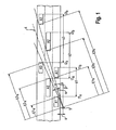
- Fig. 1 is exemplified the passage of three vehicles A1, A2, A3, which drive through a radar cone 4 with an opening angle ⁇ , the main beam is aligned at an angle ⁇ to the road direction.
- the installation angle ⁇ can also be realized by a squint angle of the radar sensor.
- the vehicles A1, A2, A3 pass through the radar cone 4 in each case on a different lane and consequently over different distance ranges to the radar device 5.
- the vehicles A1, A2, A3 occur at a time t1 a , t2 a or t3 a at a distance E1 a , E2 a and E3 a in the radar cone 4 and at a time t1 b , t2 b and t3 b at a distance E1 b , E2 b and E3 b from the radar cone 4 from.
- they travel different distances s1, s2 or s3, ie distances of different lengths.
- the vehicle A1, A2 and A3 From the number of reflected radar oscillations between an entry and exit time t a and t b and the knowledge of a fixed distance e (product of half the wavelength of the radar and cos ⁇ ), the vehicle A1, A2 and A3, respectively During a radar oscillation travels, the respective route s1, s2 and s3, ie their length, can be determined, during which the radar device 5 receives reflected radar oscillations. Since the measurement begins with the entry of the front of the vehicle and ends with the emergence of the stern, set the routes s1, s2 and s3 from the respective driving distance d1, d2 and d3 through the radar cone 4, ie their length and the respective Vehicle length L1, L2 and L3 together (s. Fig. 2 and Fig. 3 ).
- the vehicle length L can be accurately determined from the route s only if either all vehicles pass through the same passage distance d or if the passage distance d is known and thus the vehicle length L can be determined from the respective route s.
- the primary goal is not to determine the vehicle length L, but rather to use it as a means of classifying the appropriate vehicle, it is sufficient to establish a length criterion which allows the vehicle to be clearly assigned to only one vehicle class.
- the formed radar lobe (here called diagram) is inclined to the horizontal opening angle (here called side angle) to narrow and to a horizontal angle of elevation (also called side angle here) to the roadway.
- One of the determinable traffic regulation parameters is the vehicle length. This is formed from the product of the determined vehicle speed and the duration of the presence of the vehicle in the radar cone minus the distance traveled by the vehicle when passing through the radar cone (transit route). This passage is formed as a fixed value, from the length of a predetermined distance window and the cosine of the horizontal installation angle and the horizontal opening angle.
- a classification of the vehicles, in addition to the indicated application for a vehicle-dependent speed limit may also be of interest, in addition to or instead of the speedometer z.
- the vehicle length could also be a criterion for assigning a measured speed to a vehicle in a group of vehicles of different lengths or to verify an already made assignment. For the latter application the most accurate vehicle length determination would be useful to z.
- the detected distance serves to associate the vehicle with a lane in order to identify the appropriate vehicle in a group of vehicles traveling on different lanes.
- Pulse radars determine the distance, d. H. the radial distance from reflective vehicle parts to the radar antenna over a transit time measurement and derive the speed from the transit time difference of successive measurements.
- a continuous radar device With a continuous radar device is known to be transmitted in constant amplitude and frequency continuous radar. In the case of reflection on a moving object such as a vehicle, this radar radiation experiences a frequency shift dependent on the speed of the vehicle. The radiation component reflected back into the radar device or to the radar antenna is compared with the emitted radar radiation and a frequency difference, that is formed Doppler frequency, which is proportional to the speed of the vehicle. With the emission of radar radiation in different frequencies, one obtains frequency-shifted reflection radiations, from whose phase difference the distance is derived.
- the speed and the distance are thus determined by a common measuring process in a common measurement process, whereby a one-to-one correspondence of the measured values to each other is ensured.
- a measured value determination via different measuring principles is possible, for. Example, the detection of speed over the Doppler radar principle and the detection of the speed over a pulse transit time measurement, as in EP 0 935 764 B1 exemplified.
- the fluctuation range of the distance measurement values is very large.
- the point reflections that pass from a vehicle to the radar antenna extend to the entire vehicle contour onto which the radar cross section is projected.
- the radar cross section projected onto a vehicle traveling through the radar cone changes as a function of the respective geometry of the vehicle as well as its position in the radar cone, starting from the entrance to the point of exit from the radar cone.
- a sum of measured values (set of measured values) from partial reflections is detected at each measuring time. From these measurements z. B. formed a mean value over averaging.
- the measured distance is to be understood as meaning the measured value formed.
- the invention is based on the object of further developing a method for classifying vehicles on the basis of a length criterion and a device corresponding thereto in such a way that the vehicle length can be derived more accurately in order to be able to make a finer classification of the vehicles.
- the length criterion is improved by restricting the tolerance width for the passage distance d by determining the passage distance d via the detection of distance values E and thus making the vehicle length L more accurately derivable.
- the inventive method represents a further development of a method according to the EP 0 067 905 A1 Like the method described here, as described in detail in the description of the prior art with reference to the Fig. 1 has been described, the distance s is determined based on the number of reflected radar vibrations and the distance e, the vehicle A travels during a radar oscillation.
- a radar device 5 is positioned at a distance a from the roadway at an acute horizontal setting angle ⁇ of the radar axis to the roadway direction next to a roadway having a plurality of lanes.
- the installation angle ⁇ can also be realized by a squint angle of the radar device 5.
- At an opening angle ⁇ of the radar cone 4 passes through z. B. a driving on the middle of the second lane vehicle A2 the radar cone 4 in a distance range of E2 a to E2 b over a passage distance d2 ( Fig. 2 ).
- the tolerance range of the passage distance d is additionally limited in a method according to the invention by at least one distance value E is measured.
- the restriction of the tolerance range of the passage distance d with only a distance value E is possible by this distance value E is assigned a previously determined distance d which determines by the opening angle ⁇ , the installation angle ⁇ , the distance a of the radar 5 to the road and an average vehicle width is.
- the determined travel distance s less the passage distance d then gives a measure of the vehicle length L.
- the determination of the passage distance d based on only a distance value E is very rough, but it limits the range of lengths for the passage distance d compared to the prior art, which is why the tolerance range for the vehicle length L becomes comparatively smaller.
- a measurement of the distance E at the time t2 a of a second vehicle A2 in the radar cone 4 and at the time t2 b of this vehicle A2 from the radar cone 4 are measured.
- the vehicle length L2 results.
- the tolerance range for the vehicle length L is considerably reduced.
- the route s as a limited straight line is an idealization in which the vehicle A, considered reduced to one point, retains exactly its direction of travel, ie, the vehicle lane describing the vehicle A is a straight line.
- the distance values E no longer describe a straight line but a curve whose length is necessarily longer for the straight line, ie. H. the actual transit distance d is longer than the transit distance d determined with a described two-point measurement. If the direction of travel changes, the actual distance d can be additionally extended.
- the distance measurement can also be determined in accordance with a second embodiment over the entire transit time, from which the vehicle lane, which describes the vehicle A, and thus the route s, d. H. to determine their length more precisely.
- Fig. 3 five measurement times are shown. It is clear that the distance values E after entry are as long as on a straight line parallel to the roadway direction, as long as the vehicle A is not fully retracted into the radar cone 4. Subsequently, the distance value E increases faster, which is due to the fact that the rear reflects as a reflector in addition to the vehicle side. From this it is also clear that different vehicle contours provide different waveforms, which will be discussed in more detail later. The distance values E do not follow the rule described when the vehicle A is not driving steadily in the direction of travel of the road.
- the continuous measurement of the reflection signals caused at the individual vehicles A, their speed v, their radial distance a (distance E) and optionally the measuring angle to the radar axis are determined.
- the continuous speed measurement or the distance measurement are carried out, as already described, by utilizing the Doppler radar effect or in accordance with the frequency shift keying principle in evaluation of the phase difference of reflected radar signals of different frequencies.
- the angle measurement is optionally carried out by means of two receiving antennas via a triangulation measurement.
- a planar antenna according to the DE 10 2004 040 015 B4 be used. Since the velocity v, the distance E and the measuring angle are derived from a measurement, the measured values can be unambiguously assigned to one another.
- the measuring range is limited by limiting it to a smaller angular range than given by the opening angle ⁇ .
- the measuring angle is also detected for the distance E.
- the value pairs or value triplets are continuously checked for plausibility by comparing the actual values with nominal values.
- the setpoints result from the assumption that a vehicle A at constant speed v maintains the direction of travel unchanged and the knowledge about the time interval of the measuring operations. In doing so, individual measured values that do not seem plausible, ie. H. Speeds v, distances E or measurement angles that can not be assigned to an appropriate vehicle A at the next measurement time, eg. B. resulting from multiple reflections or reflections on stationary objects, filtered out, d. H. they do not participate in averaging.
- the measurements are made z. B. over a period of about 100 ms to a few seconds, depending on the speed v between entry and exit from the radar cone 4 z. B. at a distance of 20 ms, whereby the vehicle lanes can be determined with high accuracy.
- the passage distance d can be determined more accurately and thus from the route s Specify vehicle length L more precisely.
- a length criterion that is sufficiently precise for the respective application is determined, which determines the vehicle length L more or less precisely in order to classify the vehicles A.
- the determined vehicle length L is then compared with previously stored for the individual vehicle classes typical vehicle lengths L m or vehicle length ranges to the vehicle A of a particular class, eg. As motorcycles, cars, trucks, assign.
- the classification is verified by determining a signal M associated with the vehicle A. Due to the different characteristics of the vehicles A, z. As the reflectivity of the surface and acted upon by the radar radiation profile in size and shape, cause these waveforms M m in a different profile and amplitude in the frequency or time domain.
- typical signal forms M m are determined in practice for the respective vehicle classes and stored as a pattern. The signal forms M actually obtained during the measurement are then compared with these typical signal forms M m and assigned to them. In this way, confirmation of the classification made by the length criterion is possible, without additional measurements, only with the measurement values obtained in any case.
- the measured speed v can be compared with a maximum speed and when exceeding this maximum speed, a signal is emitted, which triggers a connected to the radar camera 5 to create a recording on which the committed the traffic violation vehicle A is displayed ,
- this signal is emitted only when the speed v has exceeded the maximum speed assigned to the vehicle class to which the appropriate vehicle A can also be assigned.
- time, speed and optionally distance E also the vehicle class and / or a value for the vehicle length L specified.
- the indication of the vehicle length L and / or the vehicle class can also serve as a verification of which vehicle A in a group of vehicles A was appropriate. For such an application is z. B. the most accurate length determination of importance, which also vehicles A within a class are distinguished from each other, if they differ sufficiently by their length.
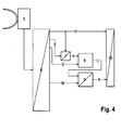
- the device comprises a radar device 5 which transmits and receives modulated continuous radar signals, and an evaluation and storage unit 6 connected to the radar 5, which is designed to obtain measured values for the speed v, the distance E and the travel distance s from the received radar signals forms as well as the waveform M, and the time points of the inputs t a and t b leakage stores.
- the evaluation and storage unit 6 is connected to a computing unit 7 which is designed such that it determines the distance d from the distance values E and the speed values v or the time difference between entry and exit times t a -t b , which is a downstream one Difference former 8 is supplied.
- the difference former 8 is also connected to the evaluation and storage unit 6 and receives from it a value for a route s. From the driving distance s and the passage distance d, the vehicle length L is determined via a difference formation in the difference former 8.
- the determined vehicle length L is a comparator 9, which is connected to the difference former 8 and the evaluation and control unit 6, provided.
- the comparator 9 is designed such that it assigns the determined vehicle length L, which it receives from the difference former 8, and assigns the signal form M to a respective vehicle class and then compares whether the same vehicle class has been assigned, which is possibly valid as confirmation of the vehicle class.
- vehicle length L and the signal form M can each be assigned to a vehicle class
- typical vehicle lengths L m and typical signal forms M m which in each case can be clearly assigned to a vehicle class, are stored in the difference former 8. If the vehicle class K is confirmed, it is forwarded together with the speed v to a camera 10 in order to map these values in the camera record.
Landscapes
- Engineering & Computer Science (AREA)
- Physics & Mathematics (AREA)
- Radar, Positioning & Navigation (AREA)
- Remote Sensing (AREA)
- General Physics & Mathematics (AREA)
- Computer Networks & Wireless Communication (AREA)
- Electromagnetism (AREA)
- Radar Systems Or Details Thereof (AREA)
- Traffic Control Systems (AREA)
Priority Applications (1)
| Application Number | Priority Date | Filing Date | Title |
|---|---|---|---|
| PL08008406T PL1990654T3 (pl) | 2007-05-07 | 2008-05-05 | Sposób i urządzenie do ustalania klasy pojazdu |
Applications Claiming Priority (1)
| Application Number | Priority Date | Filing Date | Title |
|---|---|---|---|
| DE102007022372A DE102007022372A1 (de) | 2007-05-07 | 2007-05-07 | Verfahren und Vorrichtung zur Ermittlung der Fahrzeugklasse von Fahrzeugen |
Publications (2)
| Publication Number | Publication Date |
|---|---|
| EP1990654A1 EP1990654A1 (de) | 2008-11-12 |
| EP1990654B1 true EP1990654B1 (de) | 2009-12-09 |
Family
ID=38896141
Family Applications (1)
| Application Number | Title | Priority Date | Filing Date |
|---|---|---|---|
| EP08008406A Active EP1990654B1 (de) | 2007-05-07 | 2008-05-05 | Verfahren und Vorrichtung zur Ermittlung der Fahrzeugklasse von Fahrzeugen |
Country Status (8)
| Country | Link |
|---|---|
| US (1) | US20080278366A1 (pl) |
| EP (1) | EP1990654B1 (pl) |
| AT (1) | ATE451629T1 (pl) |
| AU (1) | AU2008201990B2 (pl) |
| DE (2) | DE102007022372A1 (pl) |
| ES (1) | ES2336968T3 (pl) |
| PL (1) | PL1990654T3 (pl) |
| PT (1) | PT1990654E (pl) |
Families Citing this family (20)
| Publication number | Priority date | Publication date | Assignee | Title |
|---|---|---|---|---|
| DE102004046873A1 (de) * | 2004-09-28 | 2006-04-13 | Robert Bosch Gmbh | Radarsensor und Verfahren zur Abstands- und Geschwindigkeitsregelung |
| EP2048515B1 (de) * | 2007-10-11 | 2012-08-01 | JENOPTIK Robot GmbH | Verfahren zur Erfassung und Dokumentation von Verkehrsverstössen an einer Verkehrsampel |
| US8116968B2 (en) * | 2008-12-23 | 2012-02-14 | National Chiao Tung University | Method for identification of traffic lane boundary |
| DE102010010656B4 (de) * | 2010-03-09 | 2014-12-18 | Rtb Gmbh & Co. Kg | Verfahren und Radar-Geschwindigkeitsmesseinrichtung zur Klassifizierung von Fahrzeugen |
| EP2659471A4 (en) * | 2010-12-30 | 2014-07-23 | Sensys Networks Inc | WIRELESS AND WIRED SENSOR NODES, MICRO-RADAR, NETWORKS AND SYSTEMS |
| EP2721593B1 (en) | 2011-06-17 | 2017-04-05 | Leddartech Inc. | System and method for traffic side detection and characterization |
| USRE48914E1 (en) | 2012-03-02 | 2022-02-01 | Leddartech Inc. | System and method for multipurpose traffic detection and characterization |
| DE102012107445B8 (de) | 2012-08-14 | 2016-04-28 | Jenoptik Robot Gmbh | Verfahren zur Klassifizierung von fahrenden Fahrzeugen |
| DE102012107444B3 (de) | 2012-08-14 | 2013-03-07 | Jenoptik Robot Gmbh | Verfahren zur Klassifizierung von fahrenden Fahrzeugen durch Verfolgung einer Positionsgröße des Fahrzeuges |
| DE102013102683A1 (de) * | 2013-03-15 | 2014-09-18 | Jenoptik Robot Gmbh | Verfahren zur Erfassung von Verkehrsverstößen in einem Ampelbereich durch Heckanmessung mit einem Radargerät |
| ES2540578T3 (es) * | 2013-05-13 | 2015-07-10 | Kapsch Trafficcom Ag | Dispositivo para medir la posición de un vehículo o de una superficie de este |
| PL2804014T3 (pl) * | 2013-05-13 | 2015-10-30 | Kapsch Trafficcom Ag | Urządzenie i sposób określania cechy charakterystycznej pojazdu |
| WO2015144741A1 (en) * | 2014-03-27 | 2015-10-01 | Sony Corporation | Camera with radar system |
| EP3191869B1 (en) | 2014-09-09 | 2020-03-25 | Leddartech Inc. | Discretization of detection zone |
| CN106093458B (zh) * | 2016-06-03 | 2020-07-10 | 高文江 | 单发射波束三天线微波车速和车型检测雷达及检测方法 |
| US11313950B2 (en) * | 2019-01-15 | 2022-04-26 | Image Sensing Systems, Inc. | Machine learning based highway radar vehicle classification across multiple lanes and speeds |
| JP7608881B2 (ja) * | 2021-03-10 | 2025-01-07 | オムロン株式会社 | 車両検知装置、車両検知方法、および、車両検知プログラム |
| US20220390594A1 (en) * | 2021-06-03 | 2022-12-08 | Daniel Jamison | Vehicle identification using surface-penetrating radar |
| US20220148421A1 (en) * | 2021-09-03 | 2022-05-12 | Esther S. Massengill | Instrumented Traffic Cones for 5G/6G Networking |
| CN116430387B (zh) * | 2023-04-18 | 2026-01-30 | 深圳大学 | 一种汽车盲区的检测方法、装置、设备及介质 |
Family Cites Families (10)
| Publication number | Priority date | Publication date | Assignee | Title |
|---|---|---|---|---|
| CH654670A5 (de) | 1981-06-22 | 1986-02-28 | Zellweger Uster Ag | Verfahren und vorrichtung zur auswertung von signalen einer doppler-radar-geschwindigkeitsmesseinrichtung. |
| DE3712314A1 (de) * | 1987-04-11 | 1988-10-20 | Robot Foto Electr Kg | Verkehrsueberwachungsvorrichtung |
| DE3810357A1 (de) * | 1988-03-26 | 1989-10-05 | Licentia Gmbh | Verfahren zur lokalen verkehrsdatenerfassung und -auswertung und vorrichtung zum durchfuehren des verfahrens |
| FR2695742B1 (fr) | 1992-09-15 | 1994-10-21 | Thomson Csf | Système de calcul d'au moins un paramètre de contrôle de trafic de véhicules. |
| DE4325672A1 (de) * | 1993-07-30 | 1995-05-04 | Siemens Ag | Verfahren zur Geschwindigkeitsmessung und Klassifizierung von Fahrzeugen mittels eines Verkehrsradargerätes |
| FR2718874B1 (fr) * | 1994-04-15 | 1996-05-15 | Thomson Csf | Procédé de surveillance de trafic pour la détection automatique d'incident de véhicules. |
| ES2195127T3 (es) | 1996-04-01 | 2003-12-01 | Gatsometer Bv | Metodo y aparato para determinar la velocidad y la situacion de un vehiculo. |
| FR2843250A1 (fr) * | 2002-07-31 | 2004-02-06 | Koninkl Philips Electronics Nv | Convertisseur numerique-analogique comprenant des moyens pour ameliorer la linearite de conversion. |
| US20040227661A1 (en) * | 2003-05-12 | 2004-11-18 | Godsy Robert C. | Doppler radar system for measuring range, speed, and relative direction of movement of an object |
| DE102004040015B4 (de) | 2004-08-16 | 2006-12-07 | S.M.S., Smart Microwave Sensors Gmbh | Verfahren und Vorrichtung zur Detektion eines von einer Sendeantenne ausgesandten elektromagnetischen Signals |
-
2007
- 2007-05-07 DE DE102007022372A patent/DE102007022372A1/de not_active Withdrawn
-
2008
- 2008-05-05 PT PT08008406T patent/PT1990654E/pt unknown
- 2008-05-05 DE DE502008000235T patent/DE502008000235D1/de active Active
- 2008-05-05 PL PL08008406T patent/PL1990654T3/pl unknown
- 2008-05-05 ES ES08008406T patent/ES2336968T3/es active Active
- 2008-05-05 EP EP08008406A patent/EP1990654B1/de active Active
- 2008-05-05 AT AT08008406T patent/ATE451629T1/de active
- 2008-05-06 AU AU2008201990A patent/AU2008201990B2/en active Active
- 2008-05-09 US US12/118,342 patent/US20080278366A1/en not_active Abandoned
Also Published As
| Publication number | Publication date |
|---|---|
| ES2336968T3 (es) | 2010-04-19 |
| DE102007022372A1 (de) | 2008-11-13 |
| PL1990654T3 (pl) | 2010-07-30 |
| AU2008201990B2 (en) | 2011-04-14 |
| PT1990654E (pt) | 2010-03-19 |
| EP1990654A1 (de) | 2008-11-12 |
| AU2008201990A1 (en) | 2008-11-27 |
| US20080278366A1 (en) | 2008-11-13 |
| ATE451629T1 (de) | 2009-12-15 |
| DE502008000235D1 (de) | 2010-01-21 |
Similar Documents
| Publication | Publication Date | Title |
|---|---|---|
| EP1990654B1 (de) | Verfahren und Vorrichtung zur Ermittlung der Fahrzeugklasse von Fahrzeugen | |
| EP1990655B1 (de) | Verfahren zur beweiskräftigen Erfassung der Geschwindigkeit eines Fahrzeuges | |
| DE102012107444B3 (de) | Verfahren zur Klassifizierung von fahrenden Fahrzeugen durch Verfolgung einer Positionsgröße des Fahrzeuges | |
| EP2698648B1 (de) | Verfahren zur Klassifizierung von fahrenden Fahrzeugen | |
| EP0286910B1 (de) | Verkehrsüberwachungsvorrichtung | |
| DE112010005318B4 (de) | Fahrassistenzvorrichtung | |
| DE19749086C1 (de) | Vorrichtung zur Ermittlung fahrspurverlaufsindikativer Daten | |
| EP1853453B1 (de) | Verfahren zur objektplausibilisierung in fahrerassistenzsystemen | |
| EP2048515A1 (de) | Verfahren zur Erfassung und Dokumentation von Verkehrsverstössen an einer Verkehrsampel | |
| DE102018104243B3 (de) | Verfahren und System zur Erkennung von für ein Fahrzeug geeigneten Parklücken | |
| DE102018201220A1 (de) | Abstandsdetektionssystem, Verfahren für ein Abstandsdetektionssystem und Fahrzeug | |
| WO2011000677A1 (de) | Verfahren und system zur bestimmung einer fahrzeugklasse | |
| DE102011082545A1 (de) | Verfahren und Vorrichtung zum Steuern oder Überwachen der Öffnungsbewegung eines Karosseriebauteils | |
| EP2221640B1 (de) | Verfahren zur Messung der Geschwindigkeit eines Fahrzeuges und sichtbaren Zuordnung in einer Dokumentation | |
| WO2019038174A1 (de) | Vermeidung von totwinkelwarnungen durch gischt | |
| EP2341367B1 (de) | Verfahren und Anordnung zur Erfassung von Verkehrsverstößen in einem Ampelbereich | |
| WO2017080787A1 (de) | Seitliche leitplankenerkennung über einen abstandssensor im kfz | |
| DE102016100718A1 (de) | Verfahren zum Erkennen von Fahrspuren auf einer Fahrbahn anhand einer Häufigkeitsverteilung von Abstandswerten, Steuereinrichtung, Fahrerassistenzsystem sowie Kraftfahrzeug | |
| EP2656105B1 (de) | Verfahren zur erstellung eines bilddokumentes, in dem ein durch ein radargerät angemessenes fahrzeug identifiziert werden kann und mit diesem verfahren erstelltes bilddokument | |
| DE19754220A1 (de) | Verfahren und Vorrichtung zur Erkennung einer bevorstehenden oder möglichen Kollision | |
| EP1519203A1 (de) | Verfahren zur Ermittlung von Messeigenschaften einer Radar-Sensoreinrichtung eines Kraftfahrzeuges | |
| DE102021102301A1 (de) | Verfahren zum betreiben eines fahrassistenzsystems, computerprogrammprodukt, fahrassistenzsystem und fahrzeug | |
| EP2878971B1 (de) | Verfahren zur Geschwindigkeitsmessung eines sich auf einer Straße bewegenden Kraftfahrzeuges | |
| EP1333296B1 (de) | Verfahren zur Bestimmung eines Abstandes zwischen im Wesentlichen in einer Ebene sich befindenden Gegenständen | |
| DE602004001311T2 (de) | Verfahren und Vorrichtung für Geschwindigkeitsmessung eines Fahrzeugs, das sich auf einem bestimmten Kurvenverlauf befindet |
Legal Events
| Date | Code | Title | Description |
|---|---|---|---|
| PUAI | Public reference made under article 153(3) epc to a published international application that has entered the european phase |
Free format text: ORIGINAL CODE: 0009012 |
|
| AK | Designated contracting states |
Kind code of ref document: A1 Designated state(s): AT BE BG CH CY CZ DE DK EE ES FI FR GB GR HR HU IE IS IT LI LT LU LV MC MT NL NO PL PT RO SE SI SK TR |
|
| AX | Request for extension of the european patent |
Extension state: AL BA MK RS |
|
| GRAP | Despatch of communication of intention to grant a patent |
Free format text: ORIGINAL CODE: EPIDOSNIGR1 |
|
| 17P | Request for examination filed |
Effective date: 20090430 |
|
| AKX | Designation fees paid |
Designated state(s): AT BE BG CH CY CZ DE DK EE ES FI FR GB GR HR HU IE IS IT LI LT LU LV MC MT NL NO PL PT RO SE SI SK TR |
|
| GRAS | Grant fee paid |
Free format text: ORIGINAL CODE: EPIDOSNIGR3 |
|
| GRAA | (expected) grant |
Free format text: ORIGINAL CODE: 0009210 |
|
| AK | Designated contracting states |
Kind code of ref document: B1 Designated state(s): AT BE BG CH CY CZ DE DK EE ES FI FR GB GR HR HU IE IS IT LI LT LU LV MC MT NL NO PL PT RO SE SI SK TR |
|
| REG | Reference to a national code |
Ref country code: GB Ref legal event code: FG4D Free format text: NOT ENGLISH |
|
| REG | Reference to a national code |
Ref country code: CH Ref legal event code: EP |
|
| BECN | Be: change of holder's name |
Owner name: JENOPTIK ROBOT G.M.B.H. Effective date: 20091209 |
|
| REG | Reference to a national code |
Ref country code: IE Ref legal event code: FG4D |
|
| REF | Corresponds to: |
Ref document number: 502008000235 Country of ref document: DE Date of ref document: 20100121 Kind code of ref document: P |
|
| REG | Reference to a national code |
Ref country code: CH Ref legal event code: NV Representative=s name: ISLER & PEDRAZZINI AG |
|
| REG | Reference to a national code |
Ref country code: PT Ref legal event code: SC4A Free format text: AVAILABILITY OF NATIONAL TRANSLATION Effective date: 20100309 |
|
| REG | Reference to a national code |
Ref country code: SE Ref legal event code: TRGR |
|
| RAP2 | Party data changed (patent owner data changed or rights of a patent transferred) |
Owner name: JENOPTIK ROBOT GMBH |
|
| REG | Reference to a national code |
Ref country code: NL Ref legal event code: T3 |
|
| REG | Reference to a national code |
Ref country code: ES Ref legal event code: FG2A Ref document number: 2336968 Country of ref document: ES Kind code of ref document: T3 |
|
| PG25 | Lapsed in a contracting state [announced via postgrant information from national office to epo] |
Ref country code: FI Free format text: LAPSE BECAUSE OF FAILURE TO SUBMIT A TRANSLATION OF THE DESCRIPTION OR TO PAY THE FEE WITHIN THE PRESCRIBED TIME-LIMIT Effective date: 20091209 Ref country code: NO Free format text: LAPSE BECAUSE OF FAILURE TO SUBMIT A TRANSLATION OF THE DESCRIPTION OR TO PAY THE FEE WITHIN THE PRESCRIBED TIME-LIMIT Effective date: 20100309 Ref country code: LT Free format text: LAPSE BECAUSE OF FAILURE TO SUBMIT A TRANSLATION OF THE DESCRIPTION OR TO PAY THE FEE WITHIN THE PRESCRIBED TIME-LIMIT Effective date: 20091209 |
|
| REG | Reference to a national code |
Ref country code: NL Ref legal event code: TD Effective date: 20100423 |
|
| LTIE | Lt: invalidation of european patent or patent extension |
Effective date: 20091209 |
|
| PG25 | Lapsed in a contracting state [announced via postgrant information from national office to epo] |
Ref country code: SI Free format text: LAPSE BECAUSE OF FAILURE TO SUBMIT A TRANSLATION OF THE DESCRIPTION OR TO PAY THE FEE WITHIN THE PRESCRIBED TIME-LIMIT Effective date: 20091209 Ref country code: HR Free format text: LAPSE BECAUSE OF FAILURE TO SUBMIT A TRANSLATION OF THE DESCRIPTION OR TO PAY THE FEE WITHIN THE PRESCRIBED TIME-LIMIT Effective date: 20091209 Ref country code: LV Free format text: LAPSE BECAUSE OF FAILURE TO SUBMIT A TRANSLATION OF THE DESCRIPTION OR TO PAY THE FEE WITHIN THE PRESCRIBED TIME-LIMIT Effective date: 20091209 |
|
| REG | Reference to a national code |
Ref country code: IE Ref legal event code: FD4D |
|
| PG25 | Lapsed in a contracting state [announced via postgrant information from national office to epo] |
Ref country code: IS Free format text: LAPSE BECAUSE OF FAILURE TO SUBMIT A TRANSLATION OF THE DESCRIPTION OR TO PAY THE FEE WITHIN THE PRESCRIBED TIME-LIMIT Effective date: 20100409 Ref country code: EE Free format text: LAPSE BECAUSE OF FAILURE TO SUBMIT A TRANSLATION OF THE DESCRIPTION OR TO PAY THE FEE WITHIN THE PRESCRIBED TIME-LIMIT Effective date: 20091209 Ref country code: BG Free format text: LAPSE BECAUSE OF FAILURE TO SUBMIT A TRANSLATION OF THE DESCRIPTION OR TO PAY THE FEE WITHIN THE PRESCRIBED TIME-LIMIT Effective date: 20100309 Ref country code: RO Free format text: LAPSE BECAUSE OF FAILURE TO SUBMIT A TRANSLATION OF THE DESCRIPTION OR TO PAY THE FEE WITHIN THE PRESCRIBED TIME-LIMIT Effective date: 20091209 Ref country code: IE Free format text: LAPSE BECAUSE OF FAILURE TO SUBMIT A TRANSLATION OF THE DESCRIPTION OR TO PAY THE FEE WITHIN THE PRESCRIBED TIME-LIMIT Effective date: 20091209 |
|
| REG | Reference to a national code |
Ref country code: PL Ref legal event code: T3 |
|
| PG25 | Lapsed in a contracting state [announced via postgrant information from national office to epo] |
Ref country code: CZ Free format text: LAPSE BECAUSE OF FAILURE TO SUBMIT A TRANSLATION OF THE DESCRIPTION OR TO PAY THE FEE WITHIN THE PRESCRIBED TIME-LIMIT Effective date: 20091209 Ref country code: SK Free format text: LAPSE BECAUSE OF FAILURE TO SUBMIT A TRANSLATION OF THE DESCRIPTION OR TO PAY THE FEE WITHIN THE PRESCRIBED TIME-LIMIT Effective date: 20091209 |
|
| PLBE | No opposition filed within time limit |
Free format text: ORIGINAL CODE: 0009261 |
|
| STAA | Information on the status of an ep patent application or granted ep patent |
Free format text: STATUS: NO OPPOSITION FILED WITHIN TIME LIMIT |
|
| PG25 | Lapsed in a contracting state [announced via postgrant information from national office to epo] |
Ref country code: CY Free format text: LAPSE BECAUSE OF FAILURE TO SUBMIT A TRANSLATION OF THE DESCRIPTION OR TO PAY THE FEE WITHIN THE PRESCRIBED TIME-LIMIT Effective date: 20091209 Ref country code: GR Free format text: LAPSE BECAUSE OF FAILURE TO SUBMIT A TRANSLATION OF THE DESCRIPTION OR TO PAY THE FEE WITHIN THE PRESCRIBED TIME-LIMIT Effective date: 20100310 |
|
| 26N | No opposition filed |
Effective date: 20100910 |
|
| PG25 | Lapsed in a contracting state [announced via postgrant information from national office to epo] |
Ref country code: MC Free format text: LAPSE BECAUSE OF NON-PAYMENT OF DUE FEES Effective date: 20100531 |
|
| PG25 | Lapsed in a contracting state [announced via postgrant information from national office to epo] |
Ref country code: DK Free format text: LAPSE BECAUSE OF FAILURE TO SUBMIT A TRANSLATION OF THE DESCRIPTION OR TO PAY THE FEE WITHIN THE PRESCRIBED TIME-LIMIT Effective date: 20091209 |
|
| PG25 | Lapsed in a contracting state [announced via postgrant information from national office to epo] |
Ref country code: MT Free format text: LAPSE BECAUSE OF FAILURE TO SUBMIT A TRANSLATION OF THE DESCRIPTION OR TO PAY THE FEE WITHIN THE PRESCRIBED TIME-LIMIT Effective date: 20091209 |
|
| REG | Reference to a national code |
Ref country code: DE Ref legal event code: R082 Ref document number: 502008000235 Country of ref document: DE Representative=s name: PATENTANWAELTE OEHMKE UND KOLLEGEN, DE |
|
| REG | Reference to a national code |
Ref country code: DE Ref legal event code: R081 Ref document number: 502008000235 Country of ref document: DE Owner name: JENOPTIK ROBOT GMBH, DE Free format text: FORMER OWNER: ROBOT VISUAL SYSTEMS GMBH, 40789 MONHEIM, DE Effective date: 20110926 Ref country code: DE Ref legal event code: R082 Ref document number: 502008000235 Country of ref document: DE Representative=s name: PATENTANWAELTE OEHMKE UND KOLLEGEN, DE Effective date: 20110926 |
|
| PG25 | Lapsed in a contracting state [announced via postgrant information from national office to epo] |
Ref country code: LU Free format text: LAPSE BECAUSE OF NON-PAYMENT OF DUE FEES Effective date: 20100505 Ref country code: HU Free format text: LAPSE BECAUSE OF FAILURE TO SUBMIT A TRANSLATION OF THE DESCRIPTION OR TO PAY THE FEE WITHIN THE PRESCRIBED TIME-LIMIT Effective date: 20100610 |
|
| PG25 | Lapsed in a contracting state [announced via postgrant information from national office to epo] |
Ref country code: TR Free format text: LAPSE BECAUSE OF FAILURE TO SUBMIT A TRANSLATION OF THE DESCRIPTION OR TO PAY THE FEE WITHIN THE PRESCRIBED TIME-LIMIT Effective date: 20091209 |
|
| REG | Reference to a national code |
Ref country code: FR Ref legal event code: PLFP Year of fee payment: 9 |
|
| REG | Reference to a national code |
Ref country code: FR Ref legal event code: PLFP Year of fee payment: 10 |
|
| REG | Reference to a national code |
Ref country code: FR Ref legal event code: PLFP Year of fee payment: 11 |
|
| REG | Reference to a national code |
Ref country code: DE Ref legal event code: R082 Ref document number: 502008000235 Country of ref document: DE Representative=s name: GLEIM PETRI PATENT- UND RECHTSANWALTSPARTNERSC, DE Ref country code: DE Ref legal event code: R082 Ref document number: 502008000235 Country of ref document: DE Representative=s name: GLEIM PETRI OEHMKE PATENT- UND RECHTSANWALTSPA, DE |
|
| REG | Reference to a national code |
Ref country code: DE Ref legal event code: R082 Ref document number: 502008000235 Country of ref document: DE Representative=s name: GLEIM PETRI PATENT- UND RECHTSANWALTSPARTNERSC, DE |
|
| PGFP | Annual fee paid to national office [announced via postgrant information from national office to epo] |
Ref country code: NL Payment date: 20250522 Year of fee payment: 18 |
|
| PGFP | Annual fee paid to national office [announced via postgrant information from national office to epo] |
Ref country code: DE Payment date: 20250519 Year of fee payment: 18 Ref country code: PL Payment date: 20250418 Year of fee payment: 18 |
|
| PGFP | Annual fee paid to national office [announced via postgrant information from national office to epo] |
Ref country code: ES Payment date: 20250616 Year of fee payment: 18 Ref country code: GB Payment date: 20250522 Year of fee payment: 18 |
|
| PGFP | Annual fee paid to national office [announced via postgrant information from national office to epo] |
Ref country code: BE Payment date: 20250520 Year of fee payment: 18 Ref country code: IT Payment date: 20250530 Year of fee payment: 18 |
|
| PGFP | Annual fee paid to national office [announced via postgrant information from national office to epo] |
Ref country code: PT Payment date: 20250429 Year of fee payment: 18 |
|
| PGFP | Annual fee paid to national office [announced via postgrant information from national office to epo] |
Ref country code: FR Payment date: 20250521 Year of fee payment: 18 |
|
| PGFP | Annual fee paid to national office [announced via postgrant information from national office to epo] |
Ref country code: CH Payment date: 20250601 Year of fee payment: 18 |
|
| PGFP | Annual fee paid to national office [announced via postgrant information from national office to epo] |
Ref country code: AT Payment date: 20250519 Year of fee payment: 18 |
|
| PGFP | Annual fee paid to national office [announced via postgrant information from national office to epo] |
Ref country code: SE Payment date: 20250522 Year of fee payment: 18 |