EP1990632A2 - Vorrichtung zur Deformationsmessung und zugehöriges Herstellungsverfahren - Google Patents
Vorrichtung zur Deformationsmessung und zugehöriges Herstellungsverfahren Download PDFInfo
- Publication number
- EP1990632A2 EP1990632A2 EP08155422A EP08155422A EP1990632A2 EP 1990632 A2 EP1990632 A2 EP 1990632A2 EP 08155422 A EP08155422 A EP 08155422A EP 08155422 A EP08155422 A EP 08155422A EP 1990632 A2 EP1990632 A2 EP 1990632A2
- Authority
- EP
- European Patent Office
- Prior art keywords
- coating
- sic
- laser
- alumina
- deposited
- Prior art date
- Legal status (The legal status is an assumption and is not a legal conclusion. Google has not performed a legal analysis and makes no representation as to the accuracy of the status listed.)
- Granted
Links
Images
Classifications
-
- C—CHEMISTRY; METALLURGY
- C04—CEMENTS; CONCRETE; ARTIFICIAL STONE; CERAMICS; REFRACTORIES
- C04B—LIME, MAGNESIA; SLAG; CEMENTS; COMPOSITIONS THEREOF, e.g. MORTARS, CONCRETE OR LIKE BUILDING MATERIALS; ARTIFICIAL STONE; CERAMICS; REFRACTORIES; TREATMENT OF NATURAL STONE
- C04B41/00—After-treatment of mortars, concrete, artificial stone or ceramics; Treatment of natural stone
- C04B41/45—Coating or impregnating, e.g. injection in masonry, partial coating of green or fired ceramics, organic coating compositions for adhering together two concrete elements
- C04B41/4505—Coating or impregnating, e.g. injection in masonry, partial coating of green or fired ceramics, organic coating compositions for adhering together two concrete elements characterised by the method of application
- C04B41/4523—Coating or impregnating, e.g. injection in masonry, partial coating of green or fired ceramics, organic coating compositions for adhering together two concrete elements characterised by the method of application applied from the molten state ; Thermal spraying, e.g. plasma spraying
- C04B41/4527—Plasma spraying
-
- C—CHEMISTRY; METALLURGY
- C04—CEMENTS; CONCRETE; ARTIFICIAL STONE; CERAMICS; REFRACTORIES
- C04B—LIME, MAGNESIA; SLAG; CEMENTS; COMPOSITIONS THEREOF, e.g. MORTARS, CONCRETE OR LIKE BUILDING MATERIALS; ARTIFICIAL STONE; CERAMICS; REFRACTORIES; TREATMENT OF NATURAL STONE
- C04B41/00—After-treatment of mortars, concrete, artificial stone or ceramics; Treatment of natural stone
- C04B41/009—After-treatment of mortars, concrete, artificial stone or ceramics; Treatment of natural stone characterised by the material treated
-
- C—CHEMISTRY; METALLURGY
- C04—CEMENTS; CONCRETE; ARTIFICIAL STONE; CERAMICS; REFRACTORIES
- C04B—LIME, MAGNESIA; SLAG; CEMENTS; COMPOSITIONS THEREOF, e.g. MORTARS, CONCRETE OR LIKE BUILDING MATERIALS; ARTIFICIAL STONE; CERAMICS; REFRACTORIES; TREATMENT OF NATURAL STONE
- C04B41/00—After-treatment of mortars, concrete, artificial stone or ceramics; Treatment of natural stone
- C04B41/45—Coating or impregnating, e.g. injection in masonry, partial coating of green or fired ceramics, organic coating compositions for adhering together two concrete elements
- C04B41/52—Multiple coating or impregnating multiple coating or impregnating with the same composition or with compositions only differing in the concentration of the constituents, is classified as single coating or impregnation
-
- C—CHEMISTRY; METALLURGY
- C04—CEMENTS; CONCRETE; ARTIFICIAL STONE; CERAMICS; REFRACTORIES
- C04B—LIME, MAGNESIA; SLAG; CEMENTS; COMPOSITIONS THEREOF, e.g. MORTARS, CONCRETE OR LIKE BUILDING MATERIALS; ARTIFICIAL STONE; CERAMICS; REFRACTORIES; TREATMENT OF NATURAL STONE
- C04B41/00—After-treatment of mortars, concrete, artificial stone or ceramics; Treatment of natural stone
- C04B41/80—After-treatment of mortars, concrete, artificial stone or ceramics; Treatment of natural stone of only ceramics
- C04B41/81—Coating or impregnation
- C04B41/85—Coating or impregnation with inorganic materials
- C04B41/87—Ceramics
-
- C—CHEMISTRY; METALLURGY
- C04—CEMENTS; CONCRETE; ARTIFICIAL STONE; CERAMICS; REFRACTORIES
- C04B—LIME, MAGNESIA; SLAG; CEMENTS; COMPOSITIONS THEREOF, e.g. MORTARS, CONCRETE OR LIKE BUILDING MATERIALS; ARTIFICIAL STONE; CERAMICS; REFRACTORIES; TREATMENT OF NATURAL STONE
- C04B41/00—After-treatment of mortars, concrete, artificial stone or ceramics; Treatment of natural stone
- C04B41/80—After-treatment of mortars, concrete, artificial stone or ceramics; Treatment of natural stone of only ceramics
- C04B41/81—Coating or impregnation
- C04B41/89—Coating or impregnation for obtaining at least two superposed coatings having different compositions
-
- C—CHEMISTRY; METALLURGY
- C23—COATING METALLIC MATERIAL; COATING MATERIAL WITH METALLIC MATERIAL; CHEMICAL SURFACE TREATMENT; DIFFUSION TREATMENT OF METALLIC MATERIAL; COATING BY VACUUM EVAPORATION, BY SPUTTERING, BY ION IMPLANTATION OR BY CHEMICAL VAPOUR DEPOSITION, IN GENERAL; INHIBITING CORROSION OF METALLIC MATERIAL OR INCRUSTATION IN GENERAL
- C23C—COATING METALLIC MATERIAL; COATING MATERIAL WITH METALLIC MATERIAL; SURFACE TREATMENT OF METALLIC MATERIAL BY DIFFUSION INTO THE SURFACE, BY CHEMICAL CONVERSION OR SUBSTITUTION; COATING BY VACUUM EVAPORATION, BY SPUTTERING, BY ION IMPLANTATION OR BY CHEMICAL VAPOUR DEPOSITION, IN GENERAL
- C23C4/00—Coating by spraying the coating material in the molten state, e.g. by flame, plasma or electric discharge
- C23C4/01—Selective coating, e.g. pattern coating, without pre-treatment of the material to be coated
-
- C—CHEMISTRY; METALLURGY
- C23—COATING METALLIC MATERIAL; COATING MATERIAL WITH METALLIC MATERIAL; CHEMICAL SURFACE TREATMENT; DIFFUSION TREATMENT OF METALLIC MATERIAL; COATING BY VACUUM EVAPORATION, BY SPUTTERING, BY ION IMPLANTATION OR BY CHEMICAL VAPOUR DEPOSITION, IN GENERAL; INHIBITING CORROSION OF METALLIC MATERIAL OR INCRUSTATION IN GENERAL
- C23C—COATING METALLIC MATERIAL; COATING MATERIAL WITH METALLIC MATERIAL; SURFACE TREATMENT OF METALLIC MATERIAL BY DIFFUSION INTO THE SURFACE, BY CHEMICAL CONVERSION OR SUBSTITUTION; COATING BY VACUUM EVAPORATION, BY SPUTTERING, BY ION IMPLANTATION OR BY CHEMICAL VAPOUR DEPOSITION, IN GENERAL
- C23C4/00—Coating by spraying the coating material in the molten state, e.g. by flame, plasma or electric discharge
- C23C4/02—Pretreatment of the material to be coated, e.g. for coating on selected surface areas
-
- F—MECHANICAL ENGINEERING; LIGHTING; HEATING; WEAPONS; BLASTING
- F01—MACHINES OR ENGINES IN GENERAL; ENGINE PLANTS IN GENERAL; STEAM ENGINES
- F01D—NON-POSITIVE DISPLACEMENT MACHINES OR ENGINES, e.g. STEAM TURBINES
- F01D21/00—Shutting-down of machines or engines, e.g. in emergency; Regulating, controlling, or safety means not otherwise provided for
- F01D21/003—Arrangements for testing or measuring
-
- G—PHYSICS
- G01—MEASURING; TESTING
- G01B—MEASURING LENGTH, THICKNESS OR SIMILAR LINEAR DIMENSIONS; MEASURING ANGLES; MEASURING AREAS; MEASURING IRREGULARITIES OF SURFACES OR CONTOURS
- G01B7/00—Measuring arrangements characterised by the use of electric or magnetic techniques
- G01B7/16—Measuring arrangements characterised by the use of electric or magnetic techniques for measuring the deformation in a solid, e.g. by resistance strain gauge
- G01B7/18—Measuring arrangements characterised by the use of electric or magnetic techniques for measuring the deformation in a solid, e.g. by resistance strain gauge using change in resistance
-
- C—CHEMISTRY; METALLURGY
- C04—CEMENTS; CONCRETE; ARTIFICIAL STONE; CERAMICS; REFRACTORIES
- C04B—LIME, MAGNESIA; SLAG; CEMENTS; COMPOSITIONS THEREOF, e.g. MORTARS, CONCRETE OR LIKE BUILDING MATERIALS; ARTIFICIAL STONE; CERAMICS; REFRACTORIES; TREATMENT OF NATURAL STONE
- C04B2111/00—Mortars, concrete or artificial stone or mixtures to prepare them, characterised by specific function, property or use
- C04B2111/00474—Uses not provided for elsewhere in C04B2111/00
- C04B2111/00982—Uses not provided for elsewhere in C04B2111/00 as construction elements for space vehicles or aeroplanes
-
- Y—GENERAL TAGGING OF NEW TECHNOLOGICAL DEVELOPMENTS; GENERAL TAGGING OF CROSS-SECTIONAL TECHNOLOGIES SPANNING OVER SEVERAL SECTIONS OF THE IPC; TECHNICAL SUBJECTS COVERED BY FORMER USPC CROSS-REFERENCE ART COLLECTIONS [XRACs] AND DIGESTS
- Y10—TECHNICAL SUBJECTS COVERED BY FORMER USPC
- Y10T—TECHNICAL SUBJECTS COVERED BY FORMER US CLASSIFICATION
- Y10T29/00—Metal working
- Y10T29/49—Method of mechanical manufacture
- Y10T29/49002—Electrical device making
- Y10T29/49007—Indicating transducer
-
- Y—GENERAL TAGGING OF NEW TECHNOLOGICAL DEVELOPMENTS; GENERAL TAGGING OF CROSS-SECTIONAL TECHNOLOGIES SPANNING OVER SEVERAL SECTIONS OF THE IPC; TECHNICAL SUBJECTS COVERED BY FORMER USPC CROSS-REFERENCE ART COLLECTIONS [XRACs] AND DIGESTS
- Y10—TECHNICAL SUBJECTS COVERED BY FORMER USPC
- Y10T—TECHNICAL SUBJECTS COVERED BY FORMER US CLASSIFICATION
- Y10T29/00—Metal working
- Y10T29/49—Method of mechanical manufacture
- Y10T29/49002—Electrical device making
- Y10T29/49082—Resistor making
- Y10T29/49103—Strain gauge making
Definitions
- the present invention relates to a method for depositing a coating on a part whose surface is silicon carbide (SiC).
- SiC-coated substrate parts are used in high temperature applications, i.e. between 300 ° C and 1100 ° C.
- the substrate is for example a ceramic matrix composite (CMC), that is to say a ceramic reinforced for example by ceramic or carbon fibers.
- CMC ceramic matrix composite
- the SiC layer is intended to impart to the part a better resistance to oxidation and better mechanical properties in temperature. Thanks to these properties, these parts are used in particular in aviation turbomachines.
- a coating for example metallic or ceramic.
- a ceramic may be deposited, such a ceramic coating being intended to improve the temperature resistance of the part on which it is deposited.
- This deposit can be done either by atmospheric thermal spraying, or by means of a cement.
- the deposited ceramic is alumina Al 2 O 3 , which is thus deposited either by atmospheric thermal spraying of alumina (atmospheric powder plasma projection or flame-stick projection), or in the form of a cement based on alumina, or by combination of these methods, which are well known in the state of the art.
- the present invention aims to remedy these disadvantages.
- the aim of the invention is to propose a method for producing a coating on a part whose surface is made of SiC silicon carbide which makes it possible to improve the toughness of the interface between the SiC surface and the coating.
- the part-coating interface is more resistant to high temperatures.
- the material constituting said coating is alumina.
- Alumina is typically used as a coating because this material is good electrical insulation at high temperatures.
- Parts whose substrate is covered with a layer of silicon carbide SiC are commonly used in high temperature applications, as indicated above. It is necessary to optimize the dimensioning of these parts, for reasons of space, weight, and cost. This dimensioning is carried out in particular by laboratory tests or in operating condition, during which the deformation of these parts under thermomechanical stresses is studied. In order to measure these deformations, strain gauges, typically free-filament gauges, are used (these can also be gauges in thin layers, but their complex deposition technique makes them less used). These gauges comprise an alloy filament which is fixed on the part. As the workpiece deforms, the filament stretches or contracts, resulting in a corresponding change in electrical resistivity.
- the gauge By passing a current in the filament, it is therefore possible to measure in real time the variations of the electrical resistivity of the filament, and deformations of the piece on which it is fixed. In order to effectively measure these deformations, it is essential that the gauge adheres perfectly to the surface of the part, so that the deformations of the surface of the part are effectively transmitted to the gauge.
- the gauge is placed on a first alumina coating previously deposited on the part, then covers the gauge and the first coating by an additional alumina coating which maintains the gauge in intimate contact with the first coating.
- the gauge does not effectively measure the deformations of the surface of the workpiece, and the measurements made are therefore unreliable.
- delamination occurs at the interface at high temperatures. part / coating. This delamination occurs even in the case where the SiC layer has undergone sandblasting. It is therefore necessary to improve the adhesion between the first ceramic coating and the SiC layer, and thus with the underlying piece. This better adhesion is obtained thanks to the laser treatment of the SiC layer described above.
- the invention also relates to a device for measuring deformations of a part consisting of a substrate covered with a layer of SiC silicon carbide deposited by chemical vapor deposition.
- this device comprises a first coating of alumina deposited by atmospheric thermal spraying on the silicon carbide layer after the treatment thereof by superposition of laser impacts, a strain gauge of free filament disposed on the first coating, and an additional coating of alumina deposited by atmospheric thermal spraying on the strain gauge.
- the roughness of this surface increases, which promotes the mechanical anchoring of the coating on the SiC layer.
- the laser beam modifies the physico-chemical state of the surface of the SiC layer, which promotes the physico-chemical bonds between the coating and the SiC layer.
- the part-coating interface is more resistant to high temperatures, and the strain gauge remains integral with the SiC layer and therefore the part of which it is desired to measure deformation at high temperatures. As a result more reliable measurements of the deformations of the part to which the gauge is attached can be made.
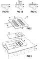
- the Figure 1A shows a part intended for high temperature applications, the substrate 10 is covered with a silicon carbide (SiC) layer 12.
- the substrate 10 is for example a ceramic matrix composite material, or a ceramic self-adhesive composite material -cicatrisante.
- the matrix of the composite may be SiC, or be formed of a plurality of glass precursor refractory ceramics layers of the ternary system Si-BC (silicon-boron-carbon).
- the reinforcement of these composites is for example constituted by carbon or ceramic fibers.
- such parts are typically thin parts, of flat rectangular or frustoconical shape, and whose size is of the order of several hundred millimeters.
- the SiC layer 12 deposited on the substrate is for example deposited by the known technique of chemical vapor deposition.
- the Figure 1B shows the same piece, with a laser 20 which emits a laser beam towards the SiC layer 12.
- the laser beam impacts the SiC layer 12 repeatedly, which creates roughness 14 on this layer 12, and causes a modification of the physico-chemical state of the surface of this layer 12.
- the result is a better adhesion of a coating deposited on the SiC layer 12, with respect to the adhesion to a layer of SiC which has not undergone this laser treatment.
- Laser processing parameters (laser type, fluence (energy per unit area), pulse duration, frequency of laser impacts, relative velocity of laser displacement / workpiece, ...) are chosen in order to obtain the best adhesion possible between the coating and the SiC layer 12.
- Nd: YAG laser whose pulse duration is 10 nanoseconds
- the number N of laser impacts per surface point is between 90 and 1000
- the fluence of the laser is between 1.8. and 2 J ⁇ cm -2
- an Nd: YAG laser can be used with a beam size of 8x4 mm 2 and an impact frequency v of 120 Hz, and operate the treatment with a fluence of 2 J ⁇ cm -2 , and a relative speed laser / piece V of 1 mm ⁇ s -1 .
- a number N equal to 480 is thus obtained for a displacement of the laser in the direction of the smallest dimension of its beam.
- a pulsed Nd: YAG laser whose pulse duration is 10 nanoseconds, with a number N of laser impacts per surface point of between 200 and 500, and whose fluence is 2 J, will be used. cm -2 .
- the figure 1C shows the same piece as on the Figure 1B , on which a coating 30 has been deposited.
- This coating 30 is typically ceramic such as mullite (3 Al 2 O 3 2 SiO 2 ), zirconia ZrO 2 or Al 2 O 3 alumina.
- This coating 30 is typically deposited by atmospheric thermal spraying.
- Deposition by atmospheric thermal spraying is generally preferred to the deposition of a cement, since the cement tends to crack at high temperatures. In fact, the deposits made by atmospheric thermal spraying are more cohesive and more tenacious.
- Thermal spraying is a group of surface coating processes in which fine particles of the material to be deposited are deposited in a molten or semi-molten state on a substrate.
- the atmospheric thermal projection may be a plasma projection or a flame projection.
- the plasma spraying technique is a blown arc plasma torch thermal projection technique which consists of introducing the material to be deposited in pulverulent form into a very energetic jet (a plasma jet) (ie say in the form of particles, here of a few tens of microns of average diameter).
- a plasma jet ie say in the form of particles, here of a few tens of microns of average diameter.
- the particles are then melted by the source and simultaneously accelerated toward the part to be coated.
- these particles crush on the surface of the piece in the form of drops, which solidify very quickly after their impact by conduction of their heat by forming lamellae on the surface of the piece.
- the stack of these lamellae perpendicular to the surface of the part gradually leads to the formation of the deposit.
- the projection is at atmospheric pressure under air.
- the growth rate of the coating is of the order of 100 microns per minute.
- the flame projection technique involves introducing into the flame of an oxyacetylene torch a rod (rod) material that is to be projected on the surface of the workpiece.
- the material is then melted, pulverized into fine particles which are accelerated towards the part to be coated on the surface of which they collapse in the form of drops, which solidify very quickly after their impact by conduction of their heat forming slats on the surface of the room.
- the stacking of these lamellae gradually leads to the formation of the deposit.
- the projection is conducted under air at atmospheric pressure.
- the growth rate of the coating is of the order of 100 microns per minute.
- Tests have been carried out by the applicant on parts with a ceramic matrix composite substrate with a layer of SiC having undergone a laser treatment as described above, and the same parts that have not undergone laser treatment. All the pieces were then coated with alumina by flame projection.
- the thermal fatigue tests (for 60 cycles, a cycle corresponding to: rise at 1100 ° C., hold for one hour at 1100 ° C., air-cooling at 300 ° C.) showed that the parts whose SiC had undergone the laser treatment showed no trace of delamination at the SiC / alumina interface, unlike the parts whose SiC layer had not undergone laser treatment.
- the parts obtained by the process according to the invention in the case where the coating is made of alumina are typically used in aeronautical turbomachines, and are, for example, nozzle flaps, mixers, combustion chamber elements.
- a device for measuring deformations is produced on a part consisting of a substrate on which a SiC layer has been deposited by chemical vapor deposition (the substrate may be, for example, one of the ceramic composites given below. above).
- This measuring device comprises a free filament gauge through which the deformations of the part are measured.
- the figure 2 shows a gauge free filament 40.
- the gauge 40 comprises a filament which is accordion-shaped as follows: the filament is bent on itself a first time to form a "U” having a given height, then it is bent on itself a second time to form a second "U” located in the same plane as the first "U” and whose branches have the same height, but inverted. The filament is thus bent over itself many times according to the same process, without the branches of the "U” touching, so as to form in a plane a grid 41.
- the branches of the "U” consecutive constitute the strands of the grid 41, which are parallel to each other.
- the grid 41 has a generally rectangular shape, and is extended on one side by the two ends 42 of the filament, which respectively extend the first branch of the first "U” and the last branch of the last “U” of the grid 41.
- the ends 42 are substantially parallel and located in the same plane as the grid 41.
- the gauge also comprises a support 43.
- This support 43 is typically an adhesive tape on which is glued the grid 41. The support 43 thus allows to maintain the configuration of the grid 41 during the manipulation of the gauge 40, and allows in particular to keep in place the loops "U” and the strands constituting the grid 41 so that these strands do not touch (this in order to avoid a short circuit in the filament).
- the support 43 has a rectangular shape extending beyond the grid 41, so that only the ends 42 of the filament protrude from the support 43.
- the support 43 is oriented so that two of its sides are parallel to the strands. of the grid 41, the other two being perpendicular.
- the ends 42 of the filament are connected to an electrical apparatus which passes a current in the filament, in order to measure in real time the variations in the electrical resistivity of the filament, and in fact the deformations of the part on which it is fixed. Indeed, when the part is deformed in the direction of the strands forming the grid 41, the filament stretches or contracts, and its electrical resistivity, varies accordingly. It is to increase the sensitivity of the measurement that the filament is bent several times on itself to form a grid 41, as described above.
- Two rectangular openings 44 are cut in the support 43 so that their largest dimension extends perpendicularly to the strands forming the grid 41.
- the openings 44 are sufficiently elongated so that all the strands of the grid 41 are seen by these openings.
- the openings 44 have a width (in the direction of the strands) limited so as to cover only a small part of the surface delimited by the grid 41.
- the largest length of the filament constituting the grid 41 remains stuck on the support 43.
- One of the openings 44 is located towards the end of the grid 41 closest to the ends 42 of the filament, and the other opening 44 is situated towards the other end of the grid 41.
- the filament of the gauge 40 is a metal alloy, for example a nickel-chromium alloy (Ni-Cr), an iron-chromium-aluminum alloy (Fe-Cr-Al), or a platinum-tungsten alloy (Pt-W) .
- the diameter of the filament is for example 18 microns at the gate 41, and 76 microns at the ends 42.
- the device for measuring the deformations of the part is produced in the following way: the SiC layer 12 (which was previously deposited on the substrate 10 of the part by chemical vapor deposition) is firstly treated by superposition of laser impacts, as indicated in the description of the Figure 1B .
- This laser treatment creates roughness on the SiC layer 14.
- a portion of the layer 12 is then deposited with a first coating 30 of alumina by atmospheric thermal spraying (plasma projection or flame projection).
- plasma projection or flame projection for example, melted-alumina powder of particle size between 22 and 45 microns can be used, which is projected by means of a plasma torch with a mixture of argon and hydrogen at 30% by volume and a power of 45 kW.
- the roughnesses 14 of the SiC layer 12 allow good adhesion of the first alumina coating to this layer 12.
- the gauge 40 is then placed on the first alumina coating 30, the support 43 being above the gate 41.
- the first alumina coating 30 here makes it possible to isolate the gauge 40 from the substrate.
- the gauge 40 is held in place by the support 43, and is deposited on the grid 41, at the windows 44, a second coating 50 of alumina similar to the first.
- the deposition of the second coating 50 is also performed by atmospheric thermal spraying.
- This second layer 50 thus has the form of two rectangular strips, each of an area equal to the area of one of the windows 44, and deposited at the location of one of these windows 44.
- the second coating 50 is therefore directly in contact with the filament of the grid 41, and maintains this filament on the first coating 30. It can then remove the support 43, the grid being now held in place by the second coating 50.
- a third coating 60 of alumina (similar to the first two) which covers the second coating 50, the parts of the grid 41 not covered by the second coating 50, and a portion of the ends 42.
- the two ends of the ends 42 are not covered by the third coating 60, in order to be connected to an electrical source for measuring the deformation of the filament of the grid 41.
- the first coating has a thickness of 100 microns
- the second coating has a thickness of 50 microns
- the third coating has a thickness of 100 microns.
- the second coating 50 and the third coating 60 together constitute an additional alumina coating that holds the dipstick 40 on the first coating 30, whereby the dipstick 40 is embedded in the alumina of the first coating 30 and the additional coating.
- the alumina block consisting of the first coating 30 and the additional coating is integral with the workpiece, even at the high temperatures (300 ° C. to 1100 ° C.) to which the workpiece is subjected. service (for example in an aviation turbomachine).
- the deformations of the part are correctly transmitted to this block of alumina, and thus to the filament of the gauge 40, which allows precise measurements of the deformations of the part.
- the method of depositing the dipstick 40 on the first layer 30 described above is given by way of example, the principle being the same for depositing another free filament gauge, provided that at the end In the deposition process, the filament of the dipstick 40 is embedded in the alumina block consisting of the first coating 30 and the additional coating.
- the method for effecting a coating on a SiC surface substrate which is described in the present invention, also covers the case where this coating is made on a solid SiC part.
Landscapes
- Chemical & Material Sciences (AREA)
- Engineering & Computer Science (AREA)
- Ceramic Engineering (AREA)
- Materials Engineering (AREA)
- Organic Chemistry (AREA)
- Structural Engineering (AREA)
- Physics & Mathematics (AREA)
- Plasma & Fusion (AREA)
- Mechanical Engineering (AREA)
- Chemical Kinetics & Catalysis (AREA)
- Metallurgy (AREA)
- General Physics & Mathematics (AREA)
- General Engineering & Computer Science (AREA)
- Inorganic Chemistry (AREA)
- Coating By Spraying Or Casting (AREA)
- Measurement Of Length, Angles, Or The Like Using Electric Or Magnetic Means (AREA)
- Other Surface Treatments For Metallic Materials (AREA)
- Ceramic Products (AREA)
- Transmission And Conversion Of Sensor Element Output (AREA)
- Length Measuring Devices By Optical Means (AREA)
Applications Claiming Priority (1)
| Application Number | Priority Date | Filing Date | Title |
|---|---|---|---|
| FR0754788A FR2915493B1 (fr) | 2007-04-30 | 2007-04-30 | Procede pour realiser un depot sur un substrat recouvert de sic |
Publications (3)
| Publication Number | Publication Date |
|---|---|
| EP1990632A2 true EP1990632A2 (de) | 2008-11-12 |
| EP1990632A3 EP1990632A3 (de) | 2013-04-03 |
| EP1990632B1 EP1990632B1 (de) | 2014-06-11 |
Family
ID=38670602
Family Applications (1)
| Application Number | Title | Priority Date | Filing Date |
|---|---|---|---|
| EP08155422.2A Active EP1990632B1 (de) | 2007-04-30 | 2008-04-30 | Vorrichtung zur Deformationsmessung und Herstellungsverfahren dafür |
Country Status (6)
| Country | Link |
|---|---|
| US (1) | US7950139B2 (de) |
| EP (1) | EP1990632B1 (de) |
| JP (1) | JP5451983B2 (de) |
| CA (1) | CA2630122C (de) |
| FR (1) | FR2915493B1 (de) |
| RU (1) | RU2466116C2 (de) |
Cited By (2)
| Publication number | Priority date | Publication date | Assignee | Title |
|---|---|---|---|---|
| FR3037138A1 (fr) * | 2015-06-05 | 2016-12-09 | Snecma | Procede de fabrication d'un dispositif de controle de contrainte et installation permettant la mise en œuvre d'un tel procede |
| CN111373245A (zh) * | 2017-12-19 | 2020-07-03 | 株式会社岛津制作所 | 热导检测器 |
Families Citing this family (11)
| Publication number | Priority date | Publication date | Assignee | Title |
|---|---|---|---|---|
| US11131014B2 (en) | 2015-04-21 | 2021-09-28 | Tocalo Co., Ltd. | Method for roughening surface of substrate, method for treating surface of substrate, method for producing thermal spray-coated member, and thermal spray-coated member |
| US10690551B2 (en) | 2016-02-12 | 2020-06-23 | Rhode Island Council On Postsecondary Education | Temperature and thermal gradient sensor for ceramic matrix composites and methods of preparation thereof |
| FR3051038B1 (fr) * | 2016-05-09 | 2018-06-01 | Safran Aircraft Engines | Fixation d'une jauge de deformation |
| US10371588B2 (en) * | 2016-07-01 | 2019-08-06 | Rhode Island Council On Postsecondary Education | High resolution strain gages for ceramic matrix composites and methods of manufacture thereof |
| US20200055258A1 (en) * | 2017-05-02 | 2020-02-20 | Ipg Photonics Corporation | High strength polymer metal composites and methods of making thereof |
| US10782190B1 (en) | 2017-12-14 | 2020-09-22 | University Of Rhode Island Board Of Trustees | Resistance temperature detector (RTD) for ceramic matrix composites |
| US11733113B2 (en) | 2018-06-14 | 2023-08-22 | Sintokogio, Ltd. | Strain element, strain element manufacturing method, and physical quantity measuring sensor |
| FR3095818B1 (fr) | 2019-05-09 | 2021-04-23 | Safran Aircraft Engines | Procédé de réalisation d'un dispositif de mesure de déformations sur une pièce en composite à matrice céramique et pièce correspondante. |
| JP7380981B2 (ja) * | 2019-06-27 | 2023-11-15 | ニデックドライブテクノロジー株式会社 | トルク検出センサおよび動力伝達装置 |
| TR201921786A1 (tr) * | 2019-12-26 | 2021-07-26 | Aselsan Elektronik Sanayi Ve Ticaret As | Isil püskürtme yolu i̇le çok katmanli serami̇k yapilar üretmek i̇çi̇n bi̇r metot |
| CN113976408B (zh) * | 2021-10-27 | 2022-08-12 | 广东工业大学 | 一种提高附着率的海工板件无吸收层激光冲击喷涂镀膜方法和装置 |
Family Cites Families (17)
| Publication number | Priority date | Publication date | Assignee | Title |
|---|---|---|---|---|
| GB893571A (en) * | 1957-04-26 | 1962-04-11 | British Iron Steel Research | Improvements in or relating to composite refractory bodies |
| US4309686A (en) * | 1980-01-28 | 1982-01-05 | Russell John D | Carbon strain gage |
| ATE50416T1 (de) * | 1985-06-10 | 1990-02-15 | Interatom | Hochtemperaturbestaendige dehnungsmesssysteme aus keramischen materialien. |
| JPH0695002B2 (ja) * | 1986-05-15 | 1994-11-24 | 株式会社共和電業 | 高温用ひずみゲ−ジの添着構造および添着方法 |
| FR2635773B1 (fr) * | 1988-08-31 | 1992-02-14 | Aerospatiale | Materiau composite a fibres de renforcement en carbone et son procede de fabrication |
| DE4015666A1 (de) * | 1990-05-16 | 1991-11-28 | Deutsche Forsch Luft Raumfahrt | Kraftaufnehmer |
| JP2861452B2 (ja) * | 1991-04-17 | 1999-02-24 | 石川島播磨重工業株式会社 | 耐環境性センサー |
| JPH06137806A (ja) * | 1992-10-27 | 1994-05-20 | Matsushita Electric Ind Co Ltd | ひずみセンサ |
| JPH0827199B2 (ja) * | 1993-03-12 | 1996-03-21 | ゼネラル・エレクトリック・カンパニイ | センサ・デカル、及びセンサを作成する方法 |
| JP3475540B2 (ja) * | 1995-01-23 | 2003-12-08 | 石川島播磨重工業株式会社 | ひずみゲージ貼付け用補助材 |
| JPH10310859A (ja) * | 1997-05-09 | 1998-11-24 | Natl Space Dev Agency Japan<Nasda> | 硬質無機材料の表面処理方法 |
| US5867886A (en) * | 1997-10-20 | 1999-02-09 | Delco Electronics Corp. | Method of making a thick film pressure sensor |
| FR2776215B1 (fr) | 1998-03-20 | 2000-06-16 | Snecma | Procede de fabrication d'un circuit regeneratif a fort flux thermique, notamment pour chambre de combustion de moteur-fusee |
| US6299988B1 (en) * | 1998-04-27 | 2001-10-09 | General Electric Company | Ceramic with preferential oxygen reactive layer |
| RU2170993C2 (ru) * | 1999-09-02 | 2001-07-20 | Санкт-Петербургский государственный электротехнический университет | Микромеханический прибор и способ его изготовления |
| JP2005170729A (ja) * | 2003-12-10 | 2005-06-30 | Toshiba Ceramics Co Ltd | 焼成用容器 |
| US7360437B2 (en) * | 2005-06-28 | 2008-04-22 | General Electric Company | Devices for evaluating material properties, and related processes |
-
2007
- 2007-04-30 FR FR0754788A patent/FR2915493B1/fr not_active Expired - Fee Related
-
2008
- 2008-04-24 US US12/108,867 patent/US7950139B2/en active Active
- 2008-04-28 CA CA2630122A patent/CA2630122C/fr active Active
- 2008-04-28 JP JP2008116868A patent/JP5451983B2/ja active Active
- 2008-04-29 RU RU2008117189/05A patent/RU2466116C2/ru active
- 2008-04-30 EP EP08155422.2A patent/EP1990632B1/de active Active
Non-Patent Citations (1)
| Title |
|---|
| None |
Cited By (3)
| Publication number | Priority date | Publication date | Assignee | Title |
|---|---|---|---|---|
| FR3037138A1 (fr) * | 2015-06-05 | 2016-12-09 | Snecma | Procede de fabrication d'un dispositif de controle de contrainte et installation permettant la mise en œuvre d'un tel procede |
| CN111373245A (zh) * | 2017-12-19 | 2020-07-03 | 株式会社岛津制作所 | 热导检测器 |
| CN111373245B (zh) * | 2017-12-19 | 2023-02-17 | 株式会社岛津制作所 | 热导检测器 |
Also Published As
| Publication number | Publication date |
|---|---|
| JP2008275617A (ja) | 2008-11-13 |
| FR2915493B1 (fr) | 2009-07-24 |
| EP1990632B1 (de) | 2014-06-11 |
| JP5451983B2 (ja) | 2014-03-26 |
| RU2466116C2 (ru) | 2012-11-10 |
| FR2915493A1 (fr) | 2008-10-31 |
| US20080264175A1 (en) | 2008-10-30 |
| RU2008117189A (ru) | 2009-11-10 |
| EP1990632A3 (de) | 2013-04-03 |
| CA2630122C (fr) | 2015-07-14 |
| US7950139B2 (en) | 2011-05-31 |
| CA2630122A1 (fr) | 2008-10-30 |
Similar Documents
| Publication | Publication Date | Title |
|---|---|---|
| EP1990632B1 (de) | Vorrichtung zur Deformationsmessung und Herstellungsverfahren dafür | |
| EP1990633B1 (de) | Vorrichtung zur Deformationsmessung und Herstellungsverfahren dafür | |
| EP0562108B1 (de) | Erosionsbeständiges und abrasionsbeständiges Mehrschichtenmaterial | |
| KR100757603B1 (ko) | 금속 기판에 환경에 대한 보호성을 제공하기 위한 피복시스템 및 이와 관련된 방법 | |
| WO2018073538A1 (fr) | Procede de revetement d'une surface d'un substrat solide par une couche comprenant un compose ceramique, et substrat revetu ainsi obtenu | |
| US20160160661A1 (en) | Abrasive coated substrate and method for manufacturing thereof | |
| FR2966455A1 (fr) | Procede pour revetir une piece d'un revetement de protection contre l'oxydation | |
| CA2931927C (fr) | Procede de reparation locale de barrieres thermiques | |
| EP2741890A1 (de) | Verfahren zur herstellung einer schutzverstärkung für die vorderkante einer leitschaufel | |
| WO2014057194A1 (fr) | Ensemble rotor-stator pour moteur a turbine a gaz | |
| KR20190087444A (ko) | 다중모드 입자 크기 분포를 갖는 스퍼터 트랩 | |
| JP2006089290A (ja) | メタライズ基板 | |
| JP2017133496A (ja) | 熱管理物品および熱管理物品を形成する方法 | |
| WO2011001117A1 (fr) | Revêtement de protection thermique pour une pièce de turbomachine et son procédé de réalisation | |
| WO2014095887A1 (fr) | Procédé de revêtement d'un substrat par un matériau abradable céramique, et revêtement ainsi obtenu | |
| EP1846588A1 (de) | Verfahren zur herstellung eines silicium- und zirconiumbasierten targets durch thermisches sprühen | |
| EP2561369B1 (de) | Hitzdrahtsensor in submillimetergrösse und zugehöriges herstellungsverfahren | |
| Husmann et al. | Pulsed laser deposition of ceramic thin films using different laser sources | |
| CA2930180C (fr) | Procede integre de frittage pour microfissuration et tenue a l'erosion des barrieres thermiques | |
| FR3043411A1 (fr) | Revetement ceramique multicouche de protection thermique a haute temperature, notamment pour application aeronautique, et son procede de fabrication | |
| JP6722073B2 (ja) | シリコン溶射膜及びその製造方法 | |
| CA3040769A1 (fr) | Piece comprenant un substrat en superalliage monocristallin a base de nickel et son procede de fabrication | |
| FR2942874A1 (fr) | Procede de depot d'un capteur pour mesures a haute temperature | |
| EP3966360A1 (de) | Verfahren zur herstellung einer vorrichtung zur messung von verformungen an einem keramischen matrixverbundteil und entsprechendes teil | |
| FR2854166A1 (fr) | Procede d'obtention d'une barriere thermique flexo-adaptative |
Legal Events
| Date | Code | Title | Description |
|---|---|---|---|
| PUAI | Public reference made under article 153(3) epc to a published international application that has entered the european phase |
Free format text: ORIGINAL CODE: 0009012 |
|
| 17P | Request for examination filed |
Effective date: 20080430 |
|
| AK | Designated contracting states |
Kind code of ref document: A2 Designated state(s): AT BE BG CH CY CZ DE DK EE ES FI FR GB GR HR HU IE IS IT LI LT LU LV MC MT NL NO PL PT RO SE SI SK TR |
|
| AX | Request for extension of the european patent |
Extension state: AL BA MK RS |
|
| PUAL | Search report despatched |
Free format text: ORIGINAL CODE: 0009013 |
|
| AK | Designated contracting states |
Kind code of ref document: A3 Designated state(s): AT BE BG CH CY CZ DE DK EE ES FI FR GB GR HR HU IE IS IT LI LT LU LV MC MT NL NO PL PT RO SE SI SK TR |
|
| AX | Request for extension of the european patent |
Extension state: AL BA MK RS |
|
| RIC1 | Information provided on ipc code assigned before grant |
Ipc: C04B 41/87 20060101ALI20130222BHEP Ipc: C04B 41/52 20060101ALI20130222BHEP Ipc: F01D 5/28 20060101ALI20130222BHEP Ipc: C04B 41/45 20060101ALI20130222BHEP Ipc: G01L 1/22 20060101ALI20130222BHEP Ipc: G01N 27/04 20060101AFI20130222BHEP Ipc: C04B 41/89 20060101ALI20130222BHEP |
|
| AKX | Designation fees paid |
Designated state(s): DE FR GB IT SE |
|
| GRAP | Despatch of communication of intention to grant a patent |
Free format text: ORIGINAL CODE: EPIDOSNIGR1 |
|
| RIC1 | Information provided on ipc code assigned before grant |
Ipc: G01L 1/22 20060101ALI20131206BHEP Ipc: C04B 41/89 20060101ALI20131206BHEP Ipc: F01D 5/28 20060101ALI20131206BHEP Ipc: C04B 41/52 20060101ALI20131206BHEP Ipc: C04B 41/45 20060101ALI20131206BHEP Ipc: G01N 27/04 20060101AFI20131206BHEP Ipc: C04B 41/87 20060101ALI20131206BHEP |
|
| INTG | Intention to grant announced |
Effective date: 20140103 |
|
| GRAS | Grant fee paid |
Free format text: ORIGINAL CODE: EPIDOSNIGR3 |
|
| GRAA | (expected) grant |
Free format text: ORIGINAL CODE: 0009210 |
|
| AK | Designated contracting states |
Kind code of ref document: B1 Designated state(s): DE FR GB IT SE |
|
| REG | Reference to a national code |
Ref country code: GB Ref legal event code: FG4D Free format text: NOT ENGLISH |
|
| REG | Reference to a national code |
Ref country code: DE Ref legal event code: R096 Ref document number: 602008032668 Country of ref document: DE Effective date: 20140724 |
|
| REG | Reference to a national code |
Ref country code: SE Ref legal event code: TRGR |
|
| REG | Reference to a national code |
Ref country code: DE Ref legal event code: R097 Ref document number: 602008032668 Country of ref document: DE |
|
| REG | Reference to a national code |
Ref country code: FR Ref legal event code: PLFP Year of fee payment: 8 |
|
| PLBE | No opposition filed within time limit |
Free format text: ORIGINAL CODE: 0009261 |
|
| STAA | Information on the status of an ep patent application or granted ep patent |
Free format text: STATUS: NO OPPOSITION FILED WITHIN TIME LIMIT |
|
| 26N | No opposition filed |
Effective date: 20150312 |
|
| REG | Reference to a national code |
Ref country code: DE Ref legal event code: R097 Ref document number: 602008032668 Country of ref document: DE Effective date: 20150312 |
|
| REG | Reference to a national code |
Ref country code: FR Ref legal event code: PLFP Year of fee payment: 9 |
|
| REG | Reference to a national code |
Ref country code: FR Ref legal event code: PLFP Year of fee payment: 10 |
|
| REG | Reference to a national code |
Ref country code: FR Ref legal event code: CD Owner name: SNECMA, FR Effective date: 20170713 |
|
| REG | Reference to a national code |
Ref country code: FR Ref legal event code: PLFP Year of fee payment: 11 |
|
| PGFP | Annual fee paid to national office [announced via postgrant information from national office to epo] |
Ref country code: DE Payment date: 20250417 Year of fee payment: 18 |
|
| PGFP | Annual fee paid to national office [announced via postgrant information from national office to epo] |
Ref country code: IT Payment date: 20250430 Year of fee payment: 18 |
|
| PGFP | Annual fee paid to national office [announced via postgrant information from national office to epo] |
Ref country code: FR Payment date: 20250428 Year of fee payment: 18 |
|
| PGFP | Annual fee paid to national office [announced via postgrant information from national office to epo] |
Ref country code: SE Payment date: 20250423 Year of fee payment: 18 |
|
| PGFP | Annual fee paid to national office [announced via postgrant information from national office to epo] |
Ref country code: GB Payment date: 20260327 Year of fee payment: 19 |