EP1990604A1 - Multi-directional projection type moire interferometer and inspection method of using the same - Google Patents
Multi-directional projection type moire interferometer and inspection method of using the same Download PDFInfo
- Publication number
- EP1990604A1 EP1990604A1 EP07021785A EP07021785A EP1990604A1 EP 1990604 A1 EP1990604 A1 EP 1990604A1 EP 07021785 A EP07021785 A EP 07021785A EP 07021785 A EP07021785 A EP 07021785A EP 1990604 A1 EP1990604 A1 EP 1990604A1
- Authority
- EP
- European Patent Office
- Prior art keywords
- illumination
- pattern
- pattern illumination
- target object
- image formation
- Prior art date
- Legal status (The legal status is an assumption and is not a legal conclusion. Google has not performed a legal analysis and makes no representation as to the accuracy of the status listed.)
- Granted
Links
Images




Classifications
-
- G—PHYSICS
- G01—MEASURING; TESTING
- G01B—MEASURING LENGTH, THICKNESS OR SIMILAR LINEAR DIMENSIONS; MEASURING ANGLES; MEASURING AREAS; MEASURING IRREGULARITIES OF SURFACES OR CONTOURS
- G01B11/00—Measuring arrangements characterised by the use of optical techniques
- G01B11/24—Measuring arrangements characterised by the use of optical techniques for measuring contours or curvatures
- G01B11/25—Measuring arrangements characterised by the use of optical techniques for measuring contours or curvatures by projecting a pattern, e.g. one or more lines, moiré fringes on the object
- G01B11/2513—Measuring arrangements characterised by the use of optical techniques for measuring contours or curvatures by projecting a pattern, e.g. one or more lines, moiré fringes on the object with several lines being projected in more than one direction, e.g. grids, patterns
-
- G—PHYSICS
- G01—MEASURING; TESTING
- G01J—MEASUREMENT OF INTENSITY, VELOCITY, SPECTRAL CONTENT, POLARISATION, PHASE OR PULSE CHARACTERISTICS OF INFRARED, VISIBLE OR ULTRAVIOLET LIGHT; COLORIMETRY; RADIATION PYROMETRY
- G01J3/00—Spectrometry; Spectrophotometry; Monochromators; Measuring colours
- G01J3/02—Details
-
- G—PHYSICS
- G01—MEASURING; TESTING
- G01B—MEASURING LENGTH, THICKNESS OR SIMILAR LINEAR DIMENSIONS; MEASURING ANGLES; MEASURING AREAS; MEASURING IRREGULARITIES OF SURFACES OR CONTOURS
- G01B11/00—Measuring arrangements characterised by the use of optical techniques
- G01B11/24—Measuring arrangements characterised by the use of optical techniques for measuring contours or curvatures
- G01B11/25—Measuring arrangements characterised by the use of optical techniques for measuring contours or curvatures by projecting a pattern, e.g. one or more lines, moiré fringes on the object
- G01B11/254—Projection of a pattern, viewing through a pattern, e.g. moiré
Definitions
- the present invention relates to a multi-directional projection type moire interferometer and an inspection method of using the same, and more particularly, to a multi-directional projection type moire interferometer capable of multi-directionally emitting the pattern illumination toward a target object to eliminate a complex shadow area of the target object according to various shapes thereof, and an inspection method of using the same.
- the conventional moire interferometer includes a plurality of projectors 3 generating a bi-directional pattern illumination and one image formation part 4.
- the plurality of projectors 3 is provided to be inclined on one side and another side of the image formation part 3, respectively.
- the projector 3 includes an illumination part 3a, a grating element 3e, a grating actuator 3f, and an emitting lens 3g to generate the pattern illumination.
- the illumination part 3a includes an illumination source 3b and a plurality of emitting lenses 3c and 3d. After the illumination that is generated from the illumination source 3b of the illumination part 3a passes through the plurality of emitting lenses 3c and 3d, the pattern illumination is formed via grating patterns formed on the grating element 3e.
- the pattern illumination according to the grating patterns passes through the emitting lens 3g and is bi-directionally emitted toward a target object 1 placed on an XY table 2.
- the XY table 2 is actuated by a table actuator 2a to move the target object into either X or Y direction.
- the image formation part 4 includes a charge-coupled device (CCD) camera 4a, an imaging lens 4b, and a filter 4c.
- the image formation part 4 takes a pattern image according to the pattern illumination reflected from the target object 1.
- a circular lamp 5 is provided below the image formation part 4.
- the circular lamp 5 is used as an illumination source when taking a particular shape of the target object 1.
- an N-bucket algorithm is applied to inspect a 3 dimensional (3D) shape of the target object 1 in a state where the target object 1 is placed on the XY table 2
- the image formation part 4 takes N images while moving the grating element 3e via the grating actuator 3f N times.
- a control unit (not shown) obtains phase information using the obtained images.
- the control unit calculates an integrated phase map in which noise is removed, and inspects a height-map and a 3D shape of the target object 1 using the calculated integrated phase map.
- the conventional projection type moire interferometer emits an illumination toward a target object and inspects the target object in a state where a plurality of projectors is provided to face each other based on the target object.
- a shadow region may be incompletely removed, which results in inaccurately inspecting the target object.
- the present invention provides a multi-directional projection type moire interferometer capable of multi-directionally emitting a pattern illumination toward a target object to remove a complex shadow region according to various shapes of the target object, and an inspection method of using the same.
- the present invention also provides a multi-directional projection type moire interferometer which can reduce a manufacturing cost since a multi-directional projection type moire interferometer can be constructed in compact by readily changing a projection direction of a pattern illumination via a rotating mirror part to emit an illumination pattern toward a target object, and controlling a movement of a grating board by installing a plurality of grating elements on the grating board.
- a multi-directional projection type moire interferometer including: an XY stage being provided to be movable by a plurality of stage actuators to move a target object into X and Y directions; an image formation part being provided above the XY stage to take a pattern image that is reflected from the target object placed on the XY stage; a first rotating mirror part being provided on one side of the image formation part to receive a pattern illumination, change the optical path of the pattern illumination, and emit the pattern illumination; a second rotating mirror part being provided on another side of the image formation part to receive a pattern illumination, change the optical path of the pattern illumination, and emit the pattern illumination; a plurality of first fixed mirror parts being provided on one side of the first rotating mirror part to emit the pattern illumination, emitted from the first rotating mirror part, toward the target object; a plurality of second fixed mirror parts being provided on another side of the second rotating mirror part to emit the pattern illumination, emitted from the second rotating mirror part, toward the target object; and
- an inspection method using a multi-directional projection type moire including: moving a target object to a setup location after adjusting a rotating angle of rotating mirrors of first and second rotating mirror parts, switching on a fifth illumination source, and implementing a secondary inspection of the target object via an image formation part; switching on any one of first through fourth illumination sources when the target object is moved to the setup location; verifying by a central control unit whether the selected illumination source is switched on; moving a grating element corresponding to the selected illumination source by 1/N pitch by moving a grating board when the selected illumination source is switched on; taking, by the image formation part, a pattern image reflected from the target object when the grating element is moved; verifying, by the central control unit, whether the grating element is an Nth pitch movement while acquiring the pattern image; obtaining a phase map using the pattern image taken in each movement when the grating element is moved by the Nth pitch; verifying, by the central control unit, whether first through fourth phase
- FIG. 1 is a diagram illustrating a conventional projection type moire interferometer
- FIG. 2 is a perspective view illustrating a configuration of a multi-directional projection type moire interferometer according to a first embodiment of the present invention
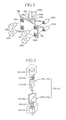
- FIG. 3 is a perspective view illustrating a configuration of a first pattern illumination generating part of FIG. 2 ;
- FIG. 4 is a perspective view illustrating a configuration of first and second rotating mirror parts of FIG. 2 ;
- FIG. 5 is a diagram illustrating a configuration of a multi-directional projection type moire interferometer of the present invention
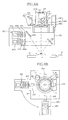
- FIGS. 6A and 6B illustrate a configuration of a multi-directional projection type moire interferometer according to a second embodiment of the present invention
- FIGS. 7A and 7B illustrate a configuration of a multi-directional projection type moire interferometer according to a third embodiment of the present invention
- FIG. 8 is a perspective illustrating a configuration of second and third pattern illumination generating parts in detail shown in FIGS. 6A and 7A respectively;
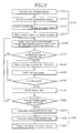
- FIG. 9 is a flowchart illustrating an inspection method using a multi-directional projection type moire interferometer of the present invention.
- FIG. 2 is a perspective view illustrating a configuration of a multi-directional projection type moire interferometer according to a first embodiment of the present invention.
- the multi-directional projection type moire interferometer includes an XY stage 10, an image formation part 110, a first rotating mirror part 120, a second rotating mirror part 130, a plurality of first fixed mirror parts 140 and 150, a plurality of second fixed mirror parts 160 and 170, and a first pattern illumination generating part 180.
- a process of multi-directionally emitting a pattern illumination toward a target object 1 and thereby inspecting the target object 1 will be sequentially described.
- the XY stage 10 is provided to be movable by a plurality of stage actuators 11 and 12 so as to move a target object 1 into X and Y directions.
- the image formation part 110 is provided above the XY stage 10 so as to take a pattern image that is reflected from the target object 1 placed on the XY stage 10.
- the image formation part 110 includes a camera 111, an imaging lens 112, and a first filter 113.
- a configuration of each component of the image formation part 110 will be described.
- the camera 111 adopts any one of a charge-coupled device (CCD) camera and a complementary metal oxide semiconductor (CMOS) camera to take a pattern image.
- the imaging lens 112 is provided below the camera 111 to image the pattern image reflected from the target object 1.
- the first filter 113 is provided below the imaging lens 112 to pass the pattern image reflected from the target object 1.
- the first filter 113 adopts any one of a frequency filter, a color filter, and an optical strength adjustment filter.
- the image formation part 110 further includes a fifth illumination source 114 in its lower portion to generate illumination for a secondary inspection of the target object 1.
- the fifth illumination source 114 includes any one of a plurality of luminescent diodes and a domed multi-layered circular lamp.
- the first rotating mirror part 120 is provided on one side of the image formation part 110 to receive the pattern illumination, change the optical path of the pattern illumination, and emit the pattern illumination. Specifically, the first rotating mirror part 120 changes an incidence angle of the pattern illumination that is emitted toward the target object 1 and thereby emits the pattern illumination. The first and the second rotating mirror parts 120 and 130 change the optical path of the pattern illumination and thereby emit the pattern illumination. As shown in FIG. 4 , the first and the second rotating mirror parts 120 and 130 include a plurality of rotating mirror elements 120a and 130a that are arranged in a multi-layer, so that ends of the rotating mirror parts 120a and 130a may vertically face each other, and multi-directionally emit the pattern illumination toward the target object 1.
- the plurality of rotating mirror elements 120a and 130a includes mirror rotating instruments 121 and 131, holders 122 and 132, and rotating mirrors 123 and 133, respectively.
- the mirror rotating instruments 121 and 131 may adopt a motor. As shown in FIG. 4 , the mirror rotating instruments 121 and 131 are mounted to one side and another side of the image formation part 110, and the holders 122 and 132 are rotatably provided above the mirror rotating instruments 121 and 131, respectively.
- the rotating mirrors 123 and 133 are provided on the holders 122 and 132 to be rotatable on the holders 122 and 132 with being supported by the mirror rotating instruments 121 and 131, respectively.
- the plurality of first fixed mirror parts 140 and 150 is provided on one side of the first rotating mirror part 120 to emit the pattern illumination, emitted from the first rotating mirror part 120, toward the target object 1.
- the plurality of second fixed mirror parts 160 and 170 is provided on another side of the second rotating mirror part 130 to emit the pattern illumination, emitted from the second rotating mirror part 130, toward the target object 1.
- the plurality of the first and the second fixed mirror parts 140, 150, 160, and 170, emitting the pattern illumination toward the target object 1, includes second filters 141, 151, 161, and 171, and fixed mirrors 142, 152, 162, and 172, respectively.
- the second filters 141, 151, 161, and 171 receive the pattern illumination emitted from the first and the second rotating mirror parts 120 and 130, and filter and emit the pattern illumination.
- the fixed mirrors 142, 152, 162, and 172 are inclined with respect to the second filters 141, 151, 161, and 171, respectively, to receive the pattern illumination emitted from the first and the second rotating mirror part, and emit the pattern illumination toward the second filters 141, 151, 161, and 171.
- the second filters 141, 151, 161, and 171 adopt any one of a frequency filter, a color filter, a polarized filter, and an optical strength adjustment filter to filter and emit the pattern illumination.
- the first pattern illumination generating part 180 is provided to be capable of emitting the pattern illumination toward the first and the second rotating mirror parts 120 and 130. Specifically, the first pattern illumination generating part 180 is provided in front of each of the first and the second mirror rotating parts 120 and 130 so as to emit the pattern illumination toward the rotating mirrors 123 and 133 of the first and the second rotating mirror parts 120 and 130 respectively. As shown in FIG.
- the first pattern illumination generating part 180 includes first through fourth illumination sources181a, 181b, 181c, and 181d, first through fourth grating elements 182a, 182b, 182c, and 182d, a grating board 183, a grating board actuator 184, and a first through fourth emitting lenses 185a, 185b, 185c, and 185d.
- first through fourth illumination sources181a, 181b, 181c, and 181d includes first through fourth illumination sources181a, 181b, 181c, and 181d, first through fourth grating elements 182a, 182b, 182c, and 182d, a grating board 183, a grating board actuator 184, and a first through fourth emitting lenses 185a, 185b, 185c, and 185d.
- the first through the fourth illumination sources181a, 181b, 181c, and 181d generate the illumination, and are installed on one side surface of the grating board 183.
- the grating board 183 includes the first through the fourth grating elements 182a, 182b, 182c, and 182d which generate the pattern illumination and emit the generated pattern illumination when the illumination is generated from the first through the fourth illumination sources 181a, 181b, 181c, and 181d.
- the first through the fourth grating elements 182a, 182b, 182c, and 182d are applied either gratings or liquid crystal devices (not shown), respectively.
- the grating board actuator 184 is provided on one side surface of the grating board 183 to vertically move the grating board 183 and thereby vertically move the first through the fourth grating elements 182a, 182b, 182c, and 182d.
- the grating board actuator 184 includes a linear motion (LM) guide 184a, an LM rail 184b, and an LM actuator 184c.
- the LM guide 184a is provided on the grating board 183, and the LM rail 184b guides the LM guide 184a.
- the LM actuator 184c drives the LM guide 184a to move along the LM rail 184b and move the grating board 183.
- the LM actuator 184c moving the grating board 183 adopts any one of a ball screw, a linear motor, and a PZT actuator.
- the PZT actuator is adopted as the LM actuator 184c, the present invention may directly install the grating board 183 in the PZT actuator.
- the first through the fourth emitting lenses 185a, 185b, 185c, and 185d are provided on one side surface of the grating board 183 to correspond to the first through the fourth grating elements 182a, 182b, 182c, and 182d so as to emit the pattern illumination that is emitted from the first through the fourth grating elements 182a, 182b, 182c, and 182d.
- the above configuration may further include a circuitry to control the multi-directional projection type moire interferometer according to the present invention.
- the circuitry of the multi-directional projection type moire interferometer includes an image acquisition unit 210, a module control unit 220, and a central control unit 230.
- FIG. 5 is a diagram illustrating a configuration of a multi-directional projection type moire interferometer of the present invention, and schematically shows the multi-directional projection type moire interferometer shown in FIG. 2 .
- FIG. 5 schematically shows the multi-directional projection type moire interferometer of FIG.
- the image acquisition part 210 receives the pattern image taken by the image formation part 110 and transmits the received pattern image.
- the module control unit 220 controls the XY stage 10, the first and the second rotating mirror parts 120 and 130, and the first pattern illumination generating part 180, so that the first pattern illumination generating part 180 may generate the pattern illumination, the first and the second rotating mirror parts 120 and 130 rotate and emit the pattern illumination toward the plurality of the first and the second fixed mirror parts 140, 150, 160, and 170, and thereby the pattern illumination is emitted toward the target object being moved by the XY stage 10.
- the module control unit 220 controlling the pattern illumination to be emitted toward the target object 1 includes a table controller 221, an illumination controller 222, a grating controller 223, and a rotating mirror controller 224.
- a table controller 221 an illumination controller 222, a grating controller 223, and a rotating mirror controller 224.
- the table controller 221 drives a plurality of stage actuators 11 and 12 to move the XY stage 10 toward X and Y directions according to control of the central control unit 230.
- the illumination controller 222 drives the first pattern illumination generating part 180 to generate the pattern illumination, or driving the fifth illumination source 114 to generate the illumination for the secondary inspection according to control of the central control unit 230.
- the fifth illumination source 114 is included in the image formation part 110.
- the grating controller 223 drives the grating board actuator 184 to move the grating board 183 according to control of the central control unit 230.
- the grating board actuator 184 is included in the first pattern illumination generating part 180 and the first through the fourth grating elements 182a, 182b, 182c, and 182d are formed on the grating bard 183.
- the rotating mirror controller 224 drives the first and the second rotating mirror parts 120 and 130 to receive the pattern illumination emitted from the first pattern illumination generating part 180, change the optical path of the pattern illumination, and emit the pattern illumination according to control of the central control unit 230.
- the central control unit 230 receives the output pattern image.
- the central control unit 230 controls the module control unit 220 to emit the pattern illumination toward the target object 1 that is being moved by the XY stage 10.
- the central control unit 230 acquires a phase map from the pattern image, calculates the height of the target object using the phase map, and inspects a 3D shape of the target object 1.
- a multi-directional projection type moire interferometer according to the second embodiment will be described with reference to the accompanying drawings.
- the multi-directional projection type moire interferometer includes an XY stage 10, an image formation part 110, a first direct reflective mirror 240, a second direct reflective mirror 250, a second pattern illumination generating part 260, a first pattern illumination case 270, a first pattern illumination elevator 280, and a pattern illumination rotating part 290.
- an XY stage 10 an image formation part 110
- a first direct reflective mirror 240 a second direct reflective mirror 250
- a second pattern illumination generating part 260 a first pattern illumination case 270
- a first pattern illumination elevator 280 includes a pattern illumination rotating part 290.
- the configuration of the above-described XY stage 10 and the image formation part 110 is the same as the XY stage 10 and the image formation part 110 that are applied to the multi-directional projection type moire interferometer according to the first embodiment.
- the image formation part case 110a is provided outside of the image formation part 110.
- the first direct reflective mirror 240 is inclined on one side of the image formation part 110 to emit the pattern illumination toward one side of the target object 1 placed on the XY stage 10 and thereby reflect a pattern image toward the image formation part 110.
- the second direct reflective mirror 250 is inclined on the other side of the image formation part 110 to be below the first direct reflective mirror 240, to emit the pattern illumination toward another side of the target object 1 paced on the XY stage 10 and thereby reflect the pattern image toward the image formation part 110.
- the second pattern illumination generating part 260 is provided one side of the first and the second direct reflective mirrors 240 and 250 to generate the pattern illumination and emit the generated pattern illumination toward the first and the second direct reflective mirrors 240 and 250.
- the first pattern illumination case 270 is formed in a straight type.
- the first and the second direct reflective mirrors 240 and 250, and the second pattern illumination generating part 260 are contained in the first pattern illumination case 270.
- the first pattern illumination elevator 280 is mounted to the image formation part case 110a of the image formation part 110, and includes a motion guide 281, a motion member 282, and a motion instrument 183 to vertically move the first pattern illumination case 270.
- the motion guide 281 is provided in the image formation part case 110a and the motion member 282 is provided on the motion guide 281 to vertically move along the motion guide 281.
- the motion instrument 283 is provided on the first pattern illumination case 270 and provides a driving force to vertically move the first pattern illumination case 270.
- the motion instrument 283 is controlled by a pattern illumination elevator control part (not shown) which controls the first pattern illumination elevator 280, to vertically move the first pattern illumination case 270 and thereby adjust a focal distance according to the target object 1.
- the pattern illumination rotating part 290 includes the first pattern illumination case 270 on its one side, and includes the first pattern illumination elevator 280 on its another side. Also, the pattern illumination rotating part 290 includes a rotating member 291, a rotary force transfer member 292, and a motor 293 to rotate the first pattern illumination case 270 into a direction indicated by an arrow of FIG. 6B and thereby multi-directionally emit the pattern illumination, emitted from the second pattern illumination generating part 260, toward the target object 1.
- the rotating member 291 includes an empty member inside, such as bushing. The inside of the rotating member 291 is mounted to the first pattern illumination elevator 280 and outside thereof is mounted to the first pattern illumination case 270.
- the rotary force transfer member 292 includes a gear or a belt to transfer to the rotary member 291 the rotary force that is generated from the motor 293.
- the motor 293 is controlled by a pattern illumination rotation control unit (not shown) to rotate the first pattern illumination case 270 and thereby multi-directionally inspect the target object 1.
- the multi-directional projection type moire interferometer includes an XY stage 10, an image formation part 110, a first direct reflective mirror 240, a second direct reflective mirror 250, a second pattern illumination generating part 260, a third direct reflective mirror 300, a fourth direct reflective mirror 310, a third pattern illumination generating part 320, a second pattern illumination case 330, and a second pattern illumination elevator 340.
- an XY stage 10 an image formation part 110
- a first direct reflective mirror 240 to direct reflective mirror 250
- a second pattern illumination generating part 260 includes a third direct reflective mirror 300, a fourth direct reflective mirror 310, a third pattern illumination generating part 320, a second pattern illumination case 330, and a second pattern illumination elevator 340.
- the configuration of the XY stage 10, the image formation part 110, the first direct reflective mirror 240, the second direct reflective mirror 250, and the second pattern illumination generating part 260 are the same as the multi-direction projection type moire interferometer according to the second embodiment, and thus further detailed descriptions will be omitted.
- the multi-directional projection type moire interferometer in addition to the first direct reflective mirror 240 which emits the pattern illumination toward one side of the target object 1 in one direction and the second direct reflective mirror 250 which emits the pattern illumination toward another side of the target object in one direction, the multi-directional projection type moire interferometer according to the third embodiment further includes the third direct reflective mirror 300, the fourth direct reflective mirror 310, the third pattern illumination generating part 320, the second pattern illumination case 330, and the second pattern illumination elevator 340 so as to multi-directionally inspect the target object 1 without rotating the second pattern illumination generating part 260.
- the third direct reflective mirror 300 is provided at the same height as the first direct reflective mirror 240 to be orthogonal to the first direct reflective mirror, to emit the pattern illumination toward one side of the target object 1 placed on the XY stage 10 in another direction and thereby reflect the pattern image toward the image formation part 110.
- the fourth direct reflective mirror 310 is provided at the same height as the second direct reflective mirror 250 to be orthogonal to the second direct reflective mirror 250, to emit the pattern illumination toward another side of the target object 1 placed on the XY stage 10 in another direction and thereby reflect the pattern image toward the image formation part 110.
- the third and the fourth direct reflective mirrors 300 and 310 emit the pattern illumination toward one side and another side of the target object 1 placed on the XY stage 10, in another direction.
- the first and the second direct reflective mirrors 240 and 250 emit the pattern illumination toward one side and another side of the target object 1, placed on the YY stage, in one direction. Therefore, it is possible to multi-directionally emit the pattern illumination via the first through the fourth direct reflective mirrors 240, 250, 300, and 310.
- the other direction designates a direction that is different from the one direction based on the target object 1, for example, a direction that is orthogonal to the one direction.
- the third pattern illumination generating part 320 is provided on one side of the third and the fourth direct reflective mirrors 300 and 310 so as to generate the pattern illumination toward the third and the fourth direct reflective mirrors 300 and 310.
- the second pattern illumination case 330 is formed in a cross type, and includes the first through the fourth direct reflective mirrors 240, 250, 300, and 310, and the second and the third pattern illumination generating parts 260 and 320.
- the second pattern illumination elevator 340 includes a motion guide which is provided on the image formation part case 110a of the image formation part 110 and vertically moves the second pattern illumination case 330, a motion member 342, and a motion instrument 343.
- the configuration and operation of each component is the same as the motion guide 281, the motion member 282, and the motion instrument 283 of the first pattern illumination elevator 280, and thus will be omitted.
- the second pattern illumination case 330 is provided on one side surface of the motion member 342 and the motion guide 341 is provided on another side surface of the motion member 342. Therefore, the motion member 342 is vertically moved along the motion guide 341.
- the first through the fourth direct reflective mirrors 240, 250, 300, and 310 which are applied to the multi-directional projection type moire interferometer according to the second and the third embodiments, may be fixed like the first and the second direct reflective mirrors 240 and 250 of FIG. 6A . Also, like the first and the second direct reflective mirrors of FIG. 7A , the first through the fourth direct reflective mirrors 240, 250, 300, and 310 may be rotated to change the optical path of the pattern illumination, that is, to adjust the incidence angle of the pattern illumination that is emitted toward the target object 1.
- the first through the fourth direct reflective mirrors 240, 250, 300, and 310 may further include a mirror rotating instrument 410 and a holder 420 like the first direct reflective mirror 240 of FIG. 7A .
- the first direct reflective mirror 240 indicated by a dotted line of FIG. 7A is when the first direct reflective mirror 240 installed in the second pattern illumination case 330 of FIG. 7A is viewed from a direction K, and is given to more concisely describe the configuration of the mirror rotating instrument 410 and the holder 420.
- the mirror rotating instrument 410 included in the first through the fourth direct reflective mirrors 240, 250, 300, and 310 generates the rotary force to rotate the first through the fourth direct reflective mirrors 240, 250, 300, and 310.
- the holder 420 is mounted to the mirror rotating instrument 410 to support the first through the fourth direct reflective mirrors 240, 250, 300, and 310.
- the second and the third pattern illumination generating parts 260 and 320 which are applied to the multi-directional projection type moire interferometer according to the second and the third embodiments, may include first and second illumination sources 181a and 181b, first and second grating elements 182a and 182b, a grating board 183a, a grating board actuator 184, and first and second emitting lenses 185a and 185b so as to generate the pattern illumination and emit the generated pattern illumination.
- the configuration and operation of each component is the same as the first pattern illumination part 180 of FIG. 3 which is applied to the multi-directional projection type moire interferometer according to the first embodiment, and thus further descriptions will be omitted here.
- the pattern illumination emitted from the first and the second emitting lenses 185a and 185b is emitted toward the first and the second direct reflective mirrors 240 and 250, respectively, or is emitted to the third and the fourth direct reflective mirrors 300 and 310, respectively.
- the grating board 183a includes two, i.e. the first and the second grating elements 182a and 182b, whereas the grating board 183 of FIG. 3 , which is applied to the multi-directional projection type moire interferometer according to the first embodiment, includes the first through the fourth grating elements 182a, 182b, 182c, and 182d of FIG. 3 , which is different.
- a cooler 350 that is applied to the multi-directional projection type moire interferometer according to the second and the third embodiments may be further provided on one side of the second and the third pattern illumination generating parts 260 and 320 so as to remove the heat generated from the first and the second illumination sources 181a and 181b of the second and the third pattern illumination generating parts 260 and 320.
- the cooler 350 adopts any one of a cooling fan, a thermoelectric element, and a hit sink member to remove the heat generated from the second and the third pattern illumination generating parts 260 and 320.
- the inspection method moves the target object 1 to a setup location via the XY stage 10 after adjusting a rotating angle of the rotating mirrors 123 and 133 of the first and second rotating mirror parts 120 and 130, switching on the fifth illumination source 114, and implementing a secondary inspection of the target object 1 via the image formation part 110.
- Operation S110 of moving the target object 1 to the setup location includes operation S111 of rotating and thereby initially setting the rotating mirrors 123 and 133 of the first and the second rotating mirror parts 120 and 130 so as to multi-directionally emit the pattern illumination toward the target object 1, operation S112 of switching on the fifth illumination source 114 when the initial setup of the rotating mirrors 123 and 133 is completed, operation S113 of taking the target object 1 via the image formation part 110 and thereby inspecting a particular shape of the target object 1, and operation S114 of moving the target object 1 to the setup location when the secondary inspection is completed.
- the inspection method switches on any one of the first through the fourth illumination sources 181a, 181b, 181c, and 181d.
- the central control unit 230 verifies whether the selected illumination source is switched on. For example, when the first through the fourth illumination sources 181a, 181b, 181c, and 181d are sequentially switched on/off, the central control unit 230 verifies whether the first illumination source 181a is switched on.
- Operation S130 of verifying, by the central control unit 230, whether the selected illumination source is switched on returns to operation S120 of switching on any one of the fourth illumination sources 181a, 181b, 181c, and 181d when the selected illumination source is not switched on by verifying whether the fourth illumination sources 181a, 181b, 181c, and 181d are sequentially selected and switched on or off.
- the inspection method moves a grating element corresponding to the selected illumination source by 1/N pitch by moving the grating board 183 when the selected illumination source is switched on in operation S140.
- the inspection method moves the first grating element 182a corresponding to the selected first illumination source 181 a by 1/N pitch.
- operation S150 when the grating element is moved, the image formation part 110 takes a pattern image reflected from the target object 1.
- the central control unit 230 verifies whether the grating element is an Nth pitch movement while acquiring the pattern image.
- Operation S160 of verifying whether the grating element is the Nth pitch movement is to utilize an N bucket algorithm when inspecting a 3D shape of the target object 1.
- Operation S160 of verifying, by the central control unit 230, whether the grating element is the Nth pitch movement returns to operation S140 of moving the grating element corresponding to the selected illumination source by 1/N pitch when the Nth pitch movement of the grating element is unfinished.
- the inspection method obtains a phase map using the pattern image taken in each movement in operation S170.
- the central control unit 230 verifies whether first through fourth phase maps are obtained. For example, when the pattern image is taken via the first illumination source 181a and the first grating element 182a and thereby the phase map is obtained, the central control unit 230 stores the obtained phase map as a first phase map. Next, while sequentially switching on/off the second through the fourth illumination sources 181b, 181c, and 181d after switching off the first illumination source 181a, the central control unit 230 obtains second through fourth phase maps according thereto, and emits the pattern illumination toward the multi-directions of the target object 1.
- the central control unit 230 takes a pattern image reflected from the target object 1, obtains the first through the fourth phase maps, and verifies the result thereof.
- operation S180 of verifying, by the central control unit 230, whether the first through the fourth phase maps are obtained returns to operation S120 of switching on any one of the first through the fourth illumination sources 181a, 181 b, 181c, and 181d to obtain the first through the fourth phase maps when all the first through the fourth phase maps are not obtained.
- the central control unit 230 calculates an integrated phase map in which noise is removed using the obtained first through the fourth phase maps, and calculates an integrated height map using the integrated phase map, and thereby inspects a 3D shape of the target object.
- Operation S190 of inspecting the 3D shape of the target object 1 includes operation S191 of calculating, by the central control unit 230, the integrated phase map in which noise is removed using the first through the fourth phase maps when the first through the fourth phase maps are obtained, operation S192 of calculating, by the central control unit 230, the integrated height map using the calculated integrated phase map, and operation S193 of inspecting, by the central control unit 230, the 3D shape of the target object 1 using the calculated integrated height map.
- a multi-directional projection type moire interferometer and an inspection method using the same according to the present invention may remove a complex shadow region according to various types of shapes of a target object. Also, since the multi-directional projection type moire interferometer can be constructed in compact by readily changing a projection direction of a pattern illumination via a rotating mirror part to emit an illumination pattern toward a target object, and controlling a movement of a grating board by installing a plurality of grating elements on the grating board, a manufacturing cost can be reduced.
Landscapes
- Physics & Mathematics (AREA)
- General Physics & Mathematics (AREA)
- Engineering & Computer Science (AREA)
- Computer Vision & Pattern Recognition (AREA)
- Spectroscopy & Molecular Physics (AREA)
- Length Measuring Devices By Optical Means (AREA)
- Instruments For Measurement Of Length By Optical Means (AREA)
Abstract
Description
- The present invention relates to a multi-directional projection type moire interferometer and an inspection method of using the same, and more particularly, to a multi-directional projection type moire interferometer capable of multi-directionally emitting the pattern illumination toward a target object to eliminate a complex shadow area of the target object according to various shapes thereof, and an inspection method of using the same.
- Hereinafter, a conventional projection type moire interferometer will be described with reference to
FIG. 1 . As shown inFIG. 1 , the conventional moire interferometer includes a plurality ofprojectors 3 generating a bi-directional pattern illumination and one image formation part 4. - The plurality of
projectors 3 is provided to be inclined on one side and another side of theimage formation part 3, respectively. Theprojector 3 includes anillumination part 3a, agrating element 3e, agrating actuator 3f, and an emittinglens 3g to generate the pattern illumination. Theillumination part 3a includes anillumination source 3b and a plurality of emittinglenses illumination source 3b of theillumination part 3a passes through the plurality of emittinglenses grating element 3e. The pattern illumination according to the grating patterns passes through the emittinglens 3g and is bi-directionally emitted toward atarget object 1 placed on an XY table 2. The XY table 2 is actuated by atable actuator 2a to move the target object into either X or Y direction. - The image formation part 4 includes a charge-coupled device (CCD) camera 4a, an
imaging lens 4b, and a filter 4c. The image formation part 4 takes a pattern image according to the pattern illumination reflected from thetarget object 1. Also, a circular lamp 5 is provided below the image formation part 4. The circular lamp 5 is used as an illumination source when taking a particular shape of thetarget object 1. When an N-bucket algorithm is applied to inspect a 3 dimensional (3D) shape of thetarget object 1 in a state where thetarget object 1 is placed on the XY table 2, the image formation part 4 takes N images while moving thegrating element 3e via thegrating actuator 3f N times. When the N images are taken and obtained, a control unit (not shown) obtains phase information using the obtained images. Also, when the plurality ofprojectors 3 obtains each phase information, the control unit calculates an integrated phase map in which noise is removed, and inspects a height-map and a 3D shape of thetarget object 1 using the calculated integrated phase map. - The conventional projection type moire interferometer emits an illumination toward a target object and inspects the target object in a state where a plurality of projectors is provided to face each other based on the target object. In this case, if the target object has a very complex shape, a shadow region may be incompletely removed, which results in inaccurately inspecting the target object.
- To solve the above-described problem in the conventional art, the present invention provides a multi-directional projection type moire interferometer capable of multi-directionally emitting a pattern illumination toward a target object to remove a complex shadow region according to various shapes of the target object, and an inspection method of using the same.
- The present invention also provides a multi-directional projection type moire interferometer which can reduce a manufacturing cost since a multi-directional projection type moire interferometer can be constructed in compact by readily changing a projection direction of a pattern illumination via a rotating mirror part to emit an illumination pattern toward a target object, and controlling a movement of a grating board by installing a plurality of grating elements on the grating board.
- According to an aspect of the present invention, there is provided a multi-directional projection type moire interferometer including: an XY stage being provided to be movable by a plurality of stage actuators to move a target object into X and Y directions; an image formation part being provided above the XY stage to take a pattern image that is reflected from the target object placed on the XY stage; a first rotating mirror part being provided on one side of the image formation part to receive a pattern illumination, change the optical path of the pattern illumination, and emit the pattern illumination; a second rotating mirror part being provided on another side of the image formation part to receive a pattern illumination, change the optical path of the pattern illumination, and emit the pattern illumination; a plurality of first fixed mirror parts being provided on one side of the first rotating mirror part to emit the pattern illumination, emitted from the first rotating mirror part, toward the target object; a plurality of second fixed mirror parts being provided on another side of the second rotating mirror part to emit the pattern illumination, emitted from the second rotating mirror part, toward the target object; and a first pattern illumination generating part being provided to be capable of emitting the pattern illumination toward the first and the second rotating mirror parts, and generate the pattern illumination.
- According to another aspect of the present invention, there is provided an inspection method using a multi-directional projection type moire, the method including: moving a target object to a setup location after adjusting a rotating angle of rotating mirrors of first and second rotating mirror parts, switching on a fifth illumination source, and implementing a secondary inspection of the target object via an image formation part; switching on any one of first through fourth illumination sources when the target object is moved to the setup location; verifying by a central control unit whether the selected illumination source is switched on; moving a grating element corresponding to the selected illumination source by 1/N pitch by moving a grating board when the selected illumination source is switched on; taking, by the image formation part, a pattern image reflected from the target object when the grating element is moved; verifying, by the central control unit, whether the grating element is an Nth pitch movement while acquiring the pattern image; obtaining a phase map using the pattern image taken in each movement when the grating element is moved by the Nth pitch; verifying, by the central control unit, whether first through fourth phase maps are obtained when the phase map is obtained; and inspecting a 3D shape by calculating, by the central control unit, an integrated phase map using the obtained first through the fourth phase maps when the first through the fourth phase maps are obtained, and then calculating an integrated height map using the integrated phase map, wherein nose is removed from the integrated phase map.
- The embodiments will be described in detail with reference to the following drawings in which like reference numerals refer to like elements wherein:
-
FIG. 1 is a diagram illustrating a conventional projection type moire interferometer; -
FIG. 2 is a perspective view illustrating a configuration of a multi-directional projection type moire interferometer according to a first embodiment of the present invention; -
FIG. 3 is a perspective view illustrating a configuration of a first pattern illumination generating part ofFIG. 2 ; -
FIG. 4 is a perspective view illustrating a configuration of first and second rotating mirror parts ofFIG. 2 ; -
FIG. 5 is a diagram illustrating a configuration of a multi-directional projection type moire interferometer of the present invention; -
FIGS. 6A and 6B illustrate a configuration of a multi-directional projection type moire interferometer according to a second embodiment of the present invention; -
FIGS. 7A and 7B illustrate a configuration of a multi-directional projection type moire interferometer according to a third embodiment of the present invention; -
FIG. 8 is a perspective illustrating a configuration of second and third pattern illumination generating parts in detail shown inFIGS. 6A and7A respectively; and -
FIG. 9 is a flowchart illustrating an inspection method using a multi-directional projection type moire interferometer of the present invention. - (First Embodiment)
- Hereinafter, a first embodiment of a multi-directional projection type moire interferometer according to the present invention will be described with reference to the accompanying drawings.
-
FIG. 2 is a perspective view illustrating a configuration of a multi-directional projection type moire interferometer according to a first embodiment of the present invention. As shown inFIG. 2 , the multi-directional projection type moire interferometer includes anXY stage 10, animage formation part 110, a firstrotating mirror part 120, a secondrotating mirror part 130, a plurality of firstfixed mirror parts fixed mirror parts illumination generating part 180. Hereinafter, a process of multi-directionally emitting a pattern illumination toward atarget object 1 and thereby inspecting thetarget object 1 will be sequentially described. - The
XY stage 10 is provided to be movable by a plurality ofstage actuators target object 1 into X and Y directions. - The
image formation part 110 is provided above theXY stage 10 so as to take a pattern image that is reflected from thetarget object 1 placed on theXY stage 10. Theimage formation part 110 includes acamera 111, animaging lens 112, and afirst filter 113. Hereinafter, a configuration of each component of theimage formation part 110 will be described. - The
camera 111 adopts any one of a charge-coupled device (CCD) camera and a complementary metal oxide semiconductor (CMOS) camera to take a pattern image. Theimaging lens 112 is provided below thecamera 111 to image the pattern image reflected from thetarget object 1. Thefirst filter 113 is provided below theimaging lens 112 to pass the pattern image reflected from thetarget object 1. In this instance, thefirst filter 113 adopts any one of a frequency filter, a color filter, and an optical strength adjustment filter. Theimage formation part 110 further includes afifth illumination source 114 in its lower portion to generate illumination for a secondary inspection of thetarget object 1. Thefifth illumination source 114 includes any one of a plurality of luminescent diodes and a domed multi-layered circular lamp. - The first
rotating mirror part 120 is provided on one side of theimage formation part 110 to receive the pattern illumination, change the optical path of the pattern illumination, and emit the pattern illumination. Specifically, the firstrotating mirror part 120 changes an incidence angle of the pattern illumination that is emitted toward thetarget object 1 and thereby emits the pattern illumination. The first and the secondrotating mirror parts FIG. 4 , the first and the secondrotating mirror parts rotating mirror elements rotating mirror parts target object 1. - The plurality of
rotating mirror elements FIG. 4 , the mirror rotating instruments 121 and 131 are mounted to one side and another side of theimage formation part 110, and the holders 122 and 132 are rotatably provided above the mirror rotating instruments 121 and 131, respectively. The rotating mirrors 123 and 133 are provided on the holders 122 and 132 to be rotatable on the holders 122 and 132 with being supported by the mirror rotating instruments 121 and 131, respectively. - The plurality of first fixed
mirror parts rotating mirror part 120 to emit the pattern illumination, emitted from the firstrotating mirror part 120, toward thetarget object 1. The plurality of second fixedmirror parts rotating mirror part 130 to emit the pattern illumination, emitted from the secondrotating mirror part 130, toward thetarget object 1. - The plurality of the first and the second fixed
mirror parts target object 1, includessecond filters mirrors second filters rotating mirror parts second filters second filters target object 1, thesecond filters - The first pattern
illumination generating part 180 is provided to be capable of emitting the pattern illumination toward the first and the secondrotating mirror parts illumination generating part 180 is provided in front of each of the first and the secondmirror rotating parts rotating mirror parts FIG. 3 , the first patternillumination generating part 180, generating the pattern illumination, includes first through fourth illumination sources181a, 181b, 181c, and 181d, first through fourthgrating elements grating board 183, agrating board actuator 184, and a first through fourth emittinglenses - The first through the fourth illumination sources181a, 181b, 181c, and 181d generate the illumination, and are installed on one side surface of the
grating board 183. Thegrating board 183 includes the first through the fourthgrating elements fourth illumination sources grating elements - The
grating board actuator 184 is provided on one side surface of thegrating board 183 to vertically move thegrating board 183 and thereby vertically move the first through the fourthgrating elements grating board actuator 184 includes a linear motion (LM) guide 184a, anLM rail 184b, and anLM actuator 184c. TheLM guide 184a is provided on thegrating board 183, and theLM rail 184b guides theLM guide 184a. Also, theLM actuator 184c drives theLM guide 184a to move along theLM rail 184b and move thegrating board 183. TheLM actuator 184c moving thegrating board 183 adopts any one of a ball screw, a linear motor, and a PZT actuator. When the PZT actuator is adopted as theLM actuator 184c, the present invention may directly install thegrating board 183 in the PZT actuator. - The first through the fourth emitting
lenses grating board 183 to correspond to the first through the fourthgrating elements grating elements - The above configuration may further include a circuitry to control the multi-directional projection type moire interferometer according to the present invention. As shown in
FIG. 5 , the circuitry of the multi-directional projection type moire interferometer includes animage acquisition unit 210, amodule control unit 220, and acentral control unit 230.FIG. 5 is a diagram illustrating a configuration of a multi-directional projection type moire interferometer of the present invention, and schematically shows the multi-directional projection type moire interferometer shown inFIG. 2 . Specifically,FIG. 5 schematically shows the multi-directional projection type moire interferometer ofFIG. 2 to represent that it is possible to multi-directionally emit the pattern illumination toward thetarget object 1 based on theimage formation part 110 using the firstrotating mirror part 120, the secondrotating mirror part 130, the plurality of first fixedmirror parts mirror parts illumination generating part 180. - As shown in
FIG. 5 , theimage acquisition part 210 receives the pattern image taken by theimage formation part 110 and transmits the received pattern image. Themodule control unit 220 controls theXY stage 10, the first and the secondrotating mirror parts illumination generating part 180, so that the first patternillumination generating part 180 may generate the pattern illumination, the first and the secondrotating mirror parts mirror parts XY stage 10. - The
module control unit 220 controlling the pattern illumination to be emitted toward thetarget object 1 includes atable controller 221, anillumination controller 222, agrating controller 223, and arotating mirror controller 224. Hereinafter, the configuration of each component will be described. - The
table controller 221 drives a plurality ofstage actuators XY stage 10 toward X and Y directions according to control of thecentral control unit 230. Theillumination controller 222 drives the first patternillumination generating part 180 to generate the pattern illumination, or driving thefifth illumination source 114 to generate the illumination for the secondary inspection according to control of thecentral control unit 230. Thefifth illumination source 114 is included in theimage formation part 110. Thegrating controller 223 drives the grating board actuator 184 to move thegrating board 183 according to control of thecentral control unit 230. In this instance, thegrating board actuator 184 is included in the first patternillumination generating part 180 and the first through the fourthgrating elements grating bard 183. Also, therotating mirror controller 224 drives the first and the secondrotating mirror parts illumination generating part 180, change the optical path of the pattern illumination, and emit the pattern illumination according to control of thecentral control unit 230. - When the optical path of the pattern illumination is changed by driving of the
module control unit 220 and the pattern image, which is emitted toward and reflected from thetarget object 1, is taken by theimage formation part 110, and then the taken pattern image is output via theimage acquisition part 210, thecentral control unit 230 receives the output pattern image. Thecentral control unit 230 controls themodule control unit 220 to emit the pattern illumination toward thetarget object 1 that is being moved by theXY stage 10. When the reflected pattern image is taken via theimage formation part 10 and is transmitted via theimage acquisition part 210, thecentral control unit 230 acquires a phase map from the pattern image, calculates the height of the target object using the phase map, and inspects a 3D shape of thetarget object 1. - (Second embodiment)
- A multi-directional projection type moire interferometer according to the second embodiment will be described with reference to the accompanying drawings.
- As shown in
FIGS. 6A and 6B , the multi-directional projection type moire interferometer according to the second embodiment includes anXY stage 10, animage formation part 110, a first directreflective mirror 240, a second directreflective mirror 250, a second patternillumination generating part 260, a firstpattern illumination case 270, a firstpattern illumination elevator 280, and a patternillumination rotating part 290. Hereinafter, the configuration of each component will be described. - The configuration of the above-described
XY stage 10 and theimage formation part 110 is the same as theXY stage 10 and theimage formation part 110 that are applied to the multi-directional projection type moire interferometer according to the first embodiment. The imageformation part case 110a is provided outside of theimage formation part 110. - The first direct
reflective mirror 240 is inclined on one side of theimage formation part 110 to emit the pattern illumination toward one side of thetarget object 1 placed on theXY stage 10 and thereby reflect a pattern image toward theimage formation part 110. The second directreflective mirror 250 is inclined on the other side of theimage formation part 110 to be below the first directreflective mirror 240, to emit the pattern illumination toward another side of thetarget object 1 paced on theXY stage 10 and thereby reflect the pattern image toward theimage formation part 110. The second patternillumination generating part 260 is provided one side of the first and the second directreflective mirrors reflective mirrors pattern illumination case 270 is formed in a straight type. The first and the second directreflective mirrors illumination generating part 260 are contained in the firstpattern illumination case 270. - The first
pattern illumination elevator 280 is mounted to the imageformation part case 110a of theimage formation part 110, and includes amotion guide 281, amotion member 282, and amotion instrument 183 to vertically move the firstpattern illumination case 270. Themotion guide 281 is provided in the imageformation part case 110a and themotion member 282 is provided on themotion guide 281 to vertically move along themotion guide 281. Also, themotion instrument 283 is provided on the firstpattern illumination case 270 and provides a driving force to vertically move the firstpattern illumination case 270. Themotion instrument 283 is controlled by a pattern illumination elevator control part (not shown) which controls the firstpattern illumination elevator 280, to vertically move the firstpattern illumination case 270 and thereby adjust a focal distance according to thetarget object 1. - The pattern
illumination rotating part 290 includes the firstpattern illumination case 270 on its one side, and includes the firstpattern illumination elevator 280 on its another side. Also, the patternillumination rotating part 290 includes a rotatingmember 291, a rotaryforce transfer member 292, and amotor 293 to rotate the firstpattern illumination case 270 into a direction indicated by an arrow ofFIG. 6B and thereby multi-directionally emit the pattern illumination, emitted from the second patternillumination generating part 260, toward thetarget object 1. The rotatingmember 291 includes an empty member inside, such as bushing. The inside of the rotatingmember 291 is mounted to the firstpattern illumination elevator 280 and outside thereof is mounted to the firstpattern illumination case 270. The rotaryforce transfer member 292 includes a gear or a belt to transfer to therotary member 291 the rotary force that is generated from themotor 293. Themotor 293 is controlled by a pattern illumination rotation control unit (not shown) to rotate the firstpattern illumination case 270 and thereby multi-directionally inspect thetarget object 1. - (Third embodiment)
- A multi-directional projection type moire interferometer according to a third embodiment will be described with reference to the accompanying drawings.
- As shown in
FIGS. 7A and 7B , the multi-directional projection type moire interferometer according to the third embodiment includes anXY stage 10, animage formation part 110, a first directreflective mirror 240, a second directreflective mirror 250, a second patternillumination generating part 260, a third directreflective mirror 300, a fourth directreflective mirror 310, a third patternillumination generating part 320, a secondpattern illumination case 330, and a secondpattern illumination elevator 340. Hereinafter, a configuration of each component will be described with reference toFIGS. 7A and 7B . - In the multi-directional projection type moire interferometer according to the third embodiment, the configuration of the
XY stage 10, theimage formation part 110, the first directreflective mirror 240, the second directreflective mirror 250, and the second patternillumination generating part 260 are the same as the multi-direction projection type moire interferometer according to the second embodiment, and thus further detailed descriptions will be omitted. In this instance, in addition to the first directreflective mirror 240 which emits the pattern illumination toward one side of thetarget object 1 in one direction and the second directreflective mirror 250 which emits the pattern illumination toward another side of the target object in one direction, the multi-directional projection type moire interferometer according to the third embodiment further includes the third directreflective mirror 300, the fourth directreflective mirror 310, the third patternillumination generating part 320, the secondpattern illumination case 330, and the secondpattern illumination elevator 340 so as to multi-directionally inspect thetarget object 1 without rotating the second patternillumination generating part 260. - The third direct
reflective mirror 300 is provided at the same height as the first directreflective mirror 240 to be orthogonal to the first direct reflective mirror, to emit the pattern illumination toward one side of thetarget object 1 placed on theXY stage 10 in another direction and thereby reflect the pattern image toward theimage formation part 110. The fourth directreflective mirror 310 is provided at the same height as the second directreflective mirror 250 to be orthogonal to the second directreflective mirror 250, to emit the pattern illumination toward another side of thetarget object 1 placed on theXY stage 10 in another direction and thereby reflect the pattern image toward theimage formation part 110. As described above, the third and the fourth directreflective mirrors target object 1 placed on theXY stage 10, in another direction. Also, the first and the second directreflective mirrors target object 1, placed on the YY stage, in one direction. Therefore, it is possible to multi-directionally emit the pattern illumination via the first through the fourth directreflective mirrors target object 1, for example, a direction that is orthogonal to the one direction. The third patternillumination generating part 320 is provided on one side of the third and the fourth directreflective mirrors reflective mirrors pattern illumination case 330 is formed in a cross type, and includes the first through the fourth directreflective mirrors illumination generating parts - The second
pattern illumination elevator 340 includes a motion guide which is provided on the imageformation part case 110a of theimage formation part 110 and vertically moves the secondpattern illumination case 330, amotion member 342, and amotion instrument 343. The configuration and operation of each component is the same as themotion guide 281, themotion member 282, and themotion instrument 283 of the firstpattern illumination elevator 280, and thus will be omitted. In this instance, the secondpattern illumination case 330 is provided on one side surface of themotion member 342 and themotion guide 341 is provided on another side surface of themotion member 342. Therefore, themotion member 342 is vertically moved along themotion guide 341. - The first through the fourth direct
reflective mirrors reflective mirrors FIG. 6A . Also, like the first and the second direct reflective mirrors ofFIG. 7A , the first through the fourth directreflective mirrors target object 1. - To adjust the incidence angle of the pattern illumination, the first through the fourth direct
reflective mirrors mirror rotating instrument 410 and aholder 420 like the first directreflective mirror 240 ofFIG. 7A . The first directreflective mirror 240 indicated by a dotted line ofFIG. 7A is when the first directreflective mirror 240 installed in the secondpattern illumination case 330 ofFIG. 7A is viewed from a direction K, and is given to more concisely describe the configuration of themirror rotating instrument 410 and theholder 420. Themirror rotating instrument 410 included in the first through the fourth directreflective mirrors reflective mirrors holder 420 is mounted to themirror rotating instrument 410 to support the first through the fourth directreflective mirrors - As shown in
FIG. 8 , the second and the third patternillumination generating parts second illumination sources grating elements grating board 183a, agrating board actuator 184, and first and second emittinglenses pattern illumination part 180 ofFIG. 3 which is applied to the multi-directional projection type moire interferometer according to the first embodiment, and thus further descriptions will be omitted here. The pattern illumination emitted from the first and the second emittinglenses reflective mirrors reflective mirrors grating board 183a includes two, i.e. the first and the secondgrating elements grating board 183 ofFIG. 3 , which is applied to the multi-directional projection type moire interferometer according to the first embodiment, includes the first through the fourthgrating elements FIG. 3 , which is different. - As shown in
FIG. 7A , a cooler 350 that is applied to the multi-directional projection type moire interferometer according to the second and the third embodiments may be further provided on one side of the second and the third patternillumination generating parts second illumination sources illumination generating parts illumination generating parts - An inspection method using the multi-directional projection type moire interferometer constructed as above will be described with reference to
FIGS. 2 ,5 , and9 . - In operation S110, the inspection method moves the
target object 1 to a setup location via theXY stage 10 after adjusting a rotating angle of the rotating mirrors 123 and 133 of the first and secondrotating mirror parts fifth illumination source 114, and implementing a secondary inspection of thetarget object 1 via theimage formation part 110. - Operation S110 of moving the
target object 1 to the setup location includes operation S111 of rotating and thereby initially setting the rotating mirrors 123 and 133 of the first and the secondrotating mirror parts target object 1, operation S112 of switching on thefifth illumination source 114 when the initial setup of the rotating mirrors 123 and 133 is completed, operation S113 of taking thetarget object 1 via theimage formation part 110 and thereby inspecting a particular shape of thetarget object 1, and operation S114 of moving thetarget object 1 to the setup location when the secondary inspection is completed. - In operation S120, when the
target object 1 is moved to the setup location, the inspection method switches on any one of the first through thefourth illumination sources central control unit 230 verifies whether the selected illumination source is switched on. For example, when the first through thefourth illumination sources central control unit 230 verifies whether thefirst illumination source 181a is switched on. - Operation S130 of verifying, by the
central control unit 230, whether the selected illumination source is switched on returns to operation S120 of switching on any one of thefourth illumination sources fourth illumination sources grating board 183 when the selected illumination source is switched on in operation S140. For example, when thefirst illumination source 181a is switched on, the inspection method moves the firstgrating element 182a corresponding to the selectedfirst illumination source 181 a by 1/N pitch. - In operation S150, when the grating element is moved, the
image formation part 110 takes a pattern image reflected from thetarget object 1. In operation S160, thecentral control unit 230 verifies whether the grating element is an Nth pitch movement while acquiring the pattern image. Operation S160 of verifying whether the grating element is the Nth pitch movement is to utilize an N bucket algorithm when inspecting a 3D shape of thetarget object 1. Operation S160 of verifying, by thecentral control unit 230, whether the grating element is the Nth pitch movement returns to operation S140 of moving the grating element corresponding to the selected illumination source by 1/N pitch when the Nth pitch movement of the grating element is unfinished. Conversely, when the grating element is the Nth pitch movement, the inspection method obtains a phase map using the pattern image taken in each movement in operation S170. - In operation S180, when the phase map is obtained, the
central control unit 230 verifies whether first through fourth phase maps are obtained. For example, when the pattern image is taken via thefirst illumination source 181a and the firstgrating element 182a and thereby the phase map is obtained, thecentral control unit 230 stores the obtained phase map as a first phase map. Next, while sequentially switching on/off the second through thefourth illumination sources first illumination source 181a, thecentral control unit 230 obtains second through fourth phase maps according thereto, and emits the pattern illumination toward the multi-directions of thetarget object 1. Next, thecentral control unit 230 takes a pattern image reflected from thetarget object 1, obtains the first through the fourth phase maps, and verifies the result thereof. In this instance, operation S180 of verifying, by thecentral control unit 230, whether the first through the fourth phase maps are obtained returns to operation S120 of switching on any one of the first through thefourth illumination sources central control unit 230 calculates an integrated phase map in which noise is removed using the obtained first through the fourth phase maps, and calculates an integrated height map using the integrated phase map, and thereby inspects a 3D shape of the target object. - Operation S190 of inspecting the 3D shape of the
target object 1 includes operation S191 of calculating, by thecentral control unit 230, the integrated phase map in which noise is removed using the first through the fourth phase maps when the first through the fourth phase maps are obtained, operation S192 of calculating, by thecentral control unit 230, the integrated height map using the calculated integrated phase map, and operation S193 of inspecting, by thecentral control unit 230, the 3D shape of thetarget object 1 using the calculated integrated height map. - A multi-directional projection type moire interferometer and an inspection method using the same according to the present invention may remove a complex shadow region according to various types of shapes of a target object. Also, since the multi-directional projection type moire interferometer can be constructed in compact by readily changing a projection direction of a pattern illumination via a rotating mirror part to emit an illumination pattern toward a target object, and controlling a movement of a grating board by installing a plurality of grating elements on the grating board, a manufacturing cost can be reduced.
Claims (18)
- A multi-directional projection type moire interferometer comprising:an XY stage being provided to be movable by a plurality of stage actuators to move a target object into X and Y directions;an image formation part being provided above the XY stage to take a pattern image that is reflected from the target object placed on the XY stage;a first rotating mirror part and a second rotating mirror part being provided on one side and another side of the image formation part, respectively, to receive a pattern illumination, change the optical path of the pattern illumination, and emit the pattern illumination;a first fixed mirror part and a second fixed mirror part being provided on the first and the second rotating mirror parts, respectively, to multi-directionally emit the pattern illumination, emitted from the first and the second rotating mirror parts, toward the target object;a first pattern illumination generating part being provided to be capable of emitting the pattern illumination toward the first and the second rotating mirror parts and generate the pattern illumination,wherein the first and the second rotating mirror parts comprise rotating mirror elements that are arranged in a multi-layer so that ends of the rotating mirror parts may vertically face each other, and
each of the plurality of rotating mirror elements comprises:a mirror rotating instrument;a holder being rotatably provided above the mirror rotating instrument; anda rotating mirror being provided on the holder to rotate on the holder with being supported by the mirror rotating instrument. - The interferometer of claim 1, wherein the image formation part comprises:a camera taking the pattern image;an imaging lens being provided below the camera to concentrate the pattern image reflected from the target object; anda first filter being provided below the image lens to pass the pattern image reflected from the target object,wherein the camera adopts any one of a charge-coupled device (CCD) camera and a complementary metal oxide semiconductor (CMOS) camera, and the first filter adopts any one of a frequency filter, a color filter, and an optical strength adjustment filter.
- The interferometer of claim 1, wherein the image formation part further comprises:a fifth illumination source generating illumination for a secondary inspection of the target object,wherein the fifth illumination source includes any one of a plurality of luminescent diodes and a domed multi-layered circular lamp.
- The interferometer of claim 1, wherein each of the first and the second fixed mirror parts comprises:a second filter receiving the pattern illumination that is emitted from the first and the second rotating mirror parts, respectively, filters the received pattern illumination, and emits the filtered pattern illumination; anda fixed mirror being inclined with respect to the second filter to receive the pattern illumination that is emitted from the first and the second rotating mirror parts, respectively, and emit the pattern illumination toward the second filter,wherein the second filter adopts any one of a frequency filter, a color filter, a polarized filter, and an optical strength adjustment filter.
- The interferometer of claim 1, wherein the first pattern illumination generating part comprises:first through fourth illumination sources generating the illumination;a grating board comprising first through fourth grating elements which are provided on one sides of the first through the fourth illumination sources, respectively, to generate the pattern illumination and emit the generated pattern illumination when the illumination is generated from the first through the fourth illumination sources;a grating board actuator being provided on one side surface of the grating board to vertically move the first through the fourth grating elements and thereby vertically move the grating board; andfirst through fourth emitting lenses being provided on one side surface of the grating board to emit the pattern illumination when the pattern illumination is emitted from the first through the fourth grating elements.
- The interferometer of claim 1, wherein the first through fourth grating elements are applied either gratings or liquid crystal devices, respectively.
- The interferometer of claim 5, wherein the grating board actuator comprises:a linear motion (LM) guide being provided on the grating board;an LM rail guiding the LM guide; andan LM actuator driving the LM guide to move along the LM rail and move the grating board,wherein the LM actuator adopts any one of a ball screw, a linear motor, a piezo electric (PZT) actuator.
- The interferometer of claim 1, further comprising:an image acquisition unit receiving the pattern image taken by the image formation part and transmitting the received pattern image;a module control unit controlling the XY stage, the first and the second rotating mirror parts, and the first pattern illumination generating part, so that the first pattern illumination generating part generates the pattern illumination, the first and the second rotating mirror parts rotate and emit the pattern illumination toward a plurality of first and second fixed mirror parts, and thereby the pattern illumination is emitted toward the target object being moved by the XY stage; anda central control unit controlling the module control unit to emit the pattern illumination toward the target object being moved by the XY stage, and when a reflected pattern image is taken by the image formation part and transmitted from the image acquisition part, acquiring a phase map of the target object from the pattern image, calculating the height of the target object using the phase map, and inspecting a 3-dimensional (3D) shape of the target object.
- The interferometer of claim 8, wherein the module control unit comprises:a table controller driving a plurality of stage actuators to move the XY stage toward X and Y directions according to control of the central control unit;an illumination controller driving the first pattern illumination generating part to generate the pattern illumination, or driving a fifth illumination source to generate the illumination for a secondary inspection according to control of the central control unit, wherein the fifth illumination source is included in the image formation part;a grating controller driving a grating board actuator to move the grating board according to control of the central control unit, wherein the grating board actuator is included in the first pattern illumination generating part and a plurality of first through fourth grating elements are formed on the grating board; anda rotating mirror controller driving the first and the second rotating mirror parts to receive the pattern illumination emitted from the first pattern illumination generating part, change the optical path of the pattern illumination, and emit the pattern illumination.
- A multi-directional projection type moire interferometer comprising:an XY stage being provided to be movable by a plurality of stage actuators to move a target object;an image formation part being provided above the XY stage to include an image formation part case on its external surface and take a pattern image reflected from the target object placed on the XY stage;a first direct reflective mirror being inclined on one side of the image formation part to emit the pattern illumination toward one side of the target object placed on the XY stage in one direction and thereby reflect a pattern image toward the image formation part;a second direct reflective mirror being inclined on the other side of the image formation part to be below the first direct reflective mirror, to emit the pattern illumination toward another side of the target object placed on the XY stage in one direction and thereby reflect the pattern image toward the image formation part;a second pattern illumination generating part being provided on one side of the first and the second direct reflective mirrors to generate the pattern illumination and emit the generated pattern illumination toward the first and the second direct reflective mirrors;a first pattern illumination case containing the first and the second direct reflective mirrors and the second pattern illumination generating part;a first pattern illumination elevator being mounted to an image formation part case of the image formation part to vertically move the first pattern illumination case; anda pattern illumination rotating part including the first pattern illumination case on its one side and including the first pattern illumination elevator on its another side, to rotate the first pattern illumination case so as to multi-directionally emit the pattern illumination, emitted from the second pattern illumination generating part, toward the target object.
- A multi-directional projection type moire interferometer comprising:an XY stage being provided to be movable by a plurality of stage actuators to move a target object;an image formation part being provided above the XY stage to include an image formation part case on its external surface and take a pattern image reflected from the target object placed on the XY stage;a first direct reflective mirror being inclined on one side of the image formation part to emit the pattern illumination toward one side of the target object placed on the XY stage in one direction and reflect a pattern image toward the image formation part;a second direct reflective mirror being inclined on the other side of the image formation part in a lower portion of the first direct reflective mirror to emit the pattern illumination towards another side of the target object placed on the XY stage in one direction, and reflect the pattern image toward the image formation part;a third direct reflective mirror being provided at the same height as the first direct reflective mirror to be orthogonal to the first direct reflective mirror, to emit the pattern illumination toward one side of the target object placed on the XY stage and reflect the pattern image toward the image formation part;a fourth direct reflective mirror being provided at the same height as the second direct reflective mirror to be orthogonal to the second direct reflective mirror, to emit the pattern illumination toward another side of the target object placed on the XY stage and reflect the pattern image toward the image formation part;a second pattern illumination generating part being provided on one side of the first and the second direct reflective mirrors to generate the pattern illumination and emit the generated pattern illumination toward the first and the second direct reflective mirrors;a third pattern illumination generating part being provided on one side of the third and the fourth direct reflective mirrors to generate the pattern illumination and emit the generated pattern illumination toward the third and the fourth direct reflective mirrors;a second pattern illumination case containing the first through the fourth direct reflective mirrors, and the second and the third pattern illumination generating parts; anda second pattern illumination elevator being mounted to an image formation part case of the image formation part to vertically move the second pattern illumination case.
- The interferometer of claim 11, wherein each of the first through the fourth direct reflective mirrors further comprises a mirror rotating instrument and a holder to rotate the first through the fourth direct reflective mirrors, change the optical path of the pattern illumination, and emit the pattern illumination, and
wherein the mirror rotating instrument generates a rotary force to rotate the first through the fourth direct reflective mirrors, and the holder is installed in the mirror rotating instrument to support the first through the fourth direct reflective mirrors. - The interferometer of claim 11, wherein each of the second and the third pattern illumination generating part comprises:first and second illumination sources generating illumination;a grating board comprising first and second grating elements which are provided on one side of the first and the second illumination sources respectively to generate a pattern illumination and emit the generated pattern illumination when the illumination is generated from a plurality of the first and the second illumination sources;a grating board actuator being provided to vertically move the first and the second grating elements and thereby vertically move the grating board; andfirst and second emitting lenses being provided on the grating board to emit the pattern illumination when the pattern illumination is emitted from the first and the second grating elements.
- The interferometer of claim 11, wherein each of the second and the third pattern illumination generating parts further comprises a cooler to cool the generated heat, and
wherein the cooler adopts any one of a cooling fan, a thermoelectric element, and a hit sink member. - An inspection method using a multi-directional projection type moire, the method comprising:moving a target object to a setup location via an XY stage after adjusting a rotating angle of rotating mirrors of first and second rotating mirror parts, switching on a fifth illumination source, and implementing a secondary inspection of the target object via an image formation part;switching on any one of first through fourth illumination sources when the target object is moved to the setup location;verifying by a central control unit whether the selected illumination source is switched on;moving a grating element corresponding to the selected illumination source by 1/N pitch by moving a grating board when the selected illumination source is switched on;taking, by the image formation part, a pattern image reflected from the target object when the grating element is moved;verifying, by the central control unit, whether the grating element is an Nth pitch movement while acquiring the pattern image;obtaining a phase map using the pattern image taken in each movement when the grating element is moved by the Nth pitch;verifying, by the central control unit, whether first through fourth phase maps are obtained when the phase map is obtained; andinspecting a 3D shape of the target object by calculating, by the central control unit, an integrated phase map using the obtained first through the fourth phase maps when the first through the fourth phase maps are obtained, and then calculating an integrated height map using the integrated phase map, wherein nose is removed from the integrated phase map.
- The method of claim 15, wherein the step of verifying, by the central control unit, whether the selected illumination source is switched on returns to the step of switching any one of the first through the fourth illumination sources when the selected illumination source is not switched on by verifying whether the first through the fourth illumination sources are sequentially selected and switched on or off.
- The method of claim 15, wherein the step of verifying, by the central control unit, whether the grating element is the Nth pitch movement returns to the step of moving the grating element corresponding to the selected illumination source by 1/N pitch when the Nth pitch movement of the grating element is unfinished.
- The method of claim 15, wherein the step of verifying, by the central control unit, whether the first through the fourth phase maps are obtained returns to the step of switching on any one of the first through the fourth illumination sources to obtain the first through the fourth phase maps when all the first through the fourth phase maps are not obtained.
Applications Claiming Priority (1)
| Application Number | Priority Date | Filing Date | Title |
|---|---|---|---|
| KR1020070044563A KR100870930B1 (en) | 2007-05-08 | 2007-05-08 | Multi-directional projection moire interferometer and inspection method using the same |
Publications (2)
| Publication Number | Publication Date |
|---|---|
| EP1990604A1 true EP1990604A1 (en) | 2008-11-12 |
| EP1990604B1 EP1990604B1 (en) | 2014-12-31 |
Family
ID=39710953
Family Applications (1)
| Application Number | Title | Priority Date | Filing Date |
|---|---|---|---|
| EP07021785.6A Active EP1990604B1 (en) | 2007-05-08 | 2007-11-09 | Multi-directional projection type moire interferometer and inspection method of using the same |
Country Status (6)
| Country | Link |
|---|---|
| US (1) | US7894077B2 (en) |
| EP (1) | EP1990604B1 (en) |
| JP (1) | JP5462999B2 (en) |
| KR (1) | KR100870930B1 (en) |
| CN (1) | CN101303223B (en) |
| TW (1) | TWI351508B (en) |
Cited By (5)
| Publication number | Priority date | Publication date | Assignee | Title |
|---|---|---|---|---|
| EP2237026A1 (en) * | 2009-04-03 | 2010-10-06 | Carl Zeiss OIM GmbH | Device for optical inspection of a surface on an object |
| EP3244198A1 (en) | 2016-05-13 | 2017-11-15 | ASM Assembly Systems GmbH & Co. KG | Method and apparatus for inspecting a solder paste deposit with a digital mirror device |
| DE102010016997B4 (en) * | 2009-05-21 | 2018-11-08 | General Electric Co. | Inspection system and method with multiple image phase shift analysis |
| CN110186388A (en) * | 2019-05-13 | 2019-08-30 | 天津大学 | Synchronization phase shift measurement system and method based on white light interference spectrum |
| FR3107119A1 (en) * | 2020-02-07 | 2021-08-13 | V-Optics | System for analyzing a surface by projecting a light image |
Families Citing this family (25)
| Publication number | Priority date | Publication date | Assignee | Title |
|---|---|---|---|---|
| CN101960253B (en) * | 2008-02-26 | 2013-05-01 | 株式会社高永科技 | Three-dimensional shape measuring device and measuring method |
| US9170097B2 (en) * | 2008-04-01 | 2015-10-27 | Perceptron, Inc. | Hybrid system |
| JP2010276607A (en) * | 2009-05-27 | 2010-12-09 | Koh Young Technology Inc | Apparatus and method for measuring three-dimensional shape |
| TWI432699B (en) * | 2009-07-03 | 2014-04-01 | Koh Young Tech Inc | Method for inspecting measurement object |
| US8754936B2 (en) | 2009-07-03 | 2014-06-17 | Koh Young Technology Inc. | Three dimensional shape measurement apparatus |
| KR101379817B1 (en) * | 2009-07-07 | 2014-04-01 | 엘지디스플레이 주식회사 | Apparatus for inspecting back light assembly and apparatus for inspecting display device |
| KR101343375B1 (en) * | 2010-04-14 | 2013-12-20 | 주식회사 고영테크놀러지 | Method of checking and setting inspection apparatus |
| US9124810B2 (en) * | 2010-04-14 | 2015-09-01 | Koh Young Technology Inc. | Method of checking an inspection apparatus and method of establishing a measurement variable of the inspection apparatus |
| US8855403B2 (en) * | 2010-04-16 | 2014-10-07 | Koh Young Technology Inc. | Method of discriminating between an object region and a ground region and method of measuring three dimensional shape by using the same |
| KR101295760B1 (en) * | 2011-03-10 | 2013-08-13 | 주식회사 미르기술 | Vision inspection apparatus using multiple grid pattern |
| KR101234935B1 (en) * | 2011-06-09 | 2013-02-19 | 삼성전기주식회사 | Inspection device of illumination and inspection method of illumination |
| JP2014106094A (en) * | 2012-11-27 | 2014-06-09 | Keyence Corp | Shape measurement device |
| KR101483956B1 (en) | 2013-07-02 | 2015-01-19 | 현대오토에버 주식회사 | Apparatus for verifying assembly quality of parts and method thereof |
| US9500468B2 (en) | 2014-08-25 | 2016-11-22 | Board Of Trustees Of Michigan State University | Scanning interferometry technique for through-thickness evaluation in multi-layered transparent structures |
| US9335157B2 (en) * | 2014-10-14 | 2016-05-10 | Electronics For Imaging, Inc. | Differential lighting |
| KR101527764B1 (en) * | 2015-02-11 | 2015-06-11 | 넥스타테크놀로지 주식회사 | 3 dimension image measuring apparatus using a laser interferometer |
| FR3051551A1 (en) * | 2016-05-20 | 2017-11-24 | Univ Aix Marseille | APPARATUS AND METHOD FOR MEASURING A SURFACE OR VOLUME STATUS OF A FAR-FIELD FIELD BROADCAST OBJECT |
| KR20180044157A (en) * | 2016-10-21 | 2018-05-02 | 주식회사 고영테크놀러지 | Pattern lighting apparatus capable of installing a plurality of different pattern light sources and inspecting apparatus |
| KR101903066B1 (en) * | 2017-03-17 | 2018-10-02 | 주식회사 고영테크놀러지 | Apparatus and method for measuring three dimensional shape |
| KR102654872B1 (en) * | 2019-01-29 | 2024-04-05 | 삼성전자주식회사 | Optical apparatus using reflection geometry |
| CN114075661B (en) * | 2020-08-14 | 2022-11-18 | 长鑫存储技术有限公司 | Semiconductor deposition method and semiconductor deposition system |
| KR102540387B1 (en) * | 2021-02-10 | 2023-06-07 | (주)에이앤아이 | 3d sensor device |
| US11835418B2 (en) * | 2021-09-30 | 2023-12-05 | Opto-Alignment Technology, Inc. | Simultaneous multi-surface non-contact optical profiler |
| KR102974098B1 (en) | 2021-10-13 | 2026-06-08 | 삼성전자주식회사 | Electronic device housing and electronic device comprising thereof |
| KR102774465B1 (en) * | 2022-03-11 | 2025-03-05 | 주식회사 고영테크놀러지 | Appapatus for three-dimensional shape measurment |
Citations (2)
| Publication number | Priority date | Publication date | Assignee | Title |
|---|---|---|---|---|
| US6522777B1 (en) | 1998-07-08 | 2003-02-18 | Ppt Vision, Inc. | Combined 3D- and 2D-scanning machine-vision system and method |
| US20040105100A1 (en) | 1996-02-12 | 2004-06-03 | Lyle Shirley | Apparatus and methods for surface contour measurements |
Family Cites Families (16)
| Publication number | Priority date | Publication date | Assignee | Title |
|---|---|---|---|---|
| JPS56125606A (en) * | 1980-03-07 | 1981-10-02 | Hitachi Ltd | Stereoscopic shape detector |
| US4432239A (en) * | 1981-12-08 | 1984-02-21 | Bykov Anatoly P | Apparatus for measuring deformation |
| US4850693A (en) * | 1988-05-23 | 1989-07-25 | The United States Of America As Represented By The United States Department Of Energy | Compact portable diffraction moire interferometer |
| US5898486A (en) * | 1994-03-25 | 1999-04-27 | International Business Machines Corporation | Portable moire interferometer and corresponding moire interferometric method |
| US5868179A (en) * | 1997-03-04 | 1999-02-09 | Gilbarco Inc. | Precision fuel dispenser |
| ATE376165T1 (en) | 2000-01-10 | 2007-11-15 | Massachusetts Inst Technology | APPARATUS AND METHOD FOR SURFACE CONTOUR MEASURING |
| JP3858056B2 (en) | 2001-10-15 | 2006-12-13 | 福岡県 | Two-direction deformation simultaneous measurement device using speckle |
| CN100338434C (en) * | 2003-02-06 | 2007-09-19 | 株式会社高永科技 | Thrre-dimensional image measuring apparatus |
| KR100615576B1 (en) * | 2003-02-06 | 2006-08-25 | 주식회사 고영테크놀러지 | Three-dimensional image measuring apparatus |
| KR100540192B1 (en) * | 2003-11-11 | 2005-12-29 | 박승한 | Apparatus and method for measuring three-dimensional shape |
| JP4611782B2 (en) * | 2005-03-28 | 2011-01-12 | シチズンホールディングス株式会社 | Three-dimensional shape measuring method and measuring apparatus |
| EP1875163B1 (en) * | 2005-04-06 | 2014-06-11 | Dimensional Photonics International, Inc. | Multiple channel interferometric surface contour measurement system |
| US7538891B1 (en) * | 2005-09-30 | 2009-05-26 | California Institute Of Technology | Surface characterization based on lateral shearing of diffracted wave fronts to measure in-plane and out-of-plane displacement gradient fields |
| KR100672818B1 (en) * | 2006-01-26 | 2007-01-22 | 주식회사 고영테크놀러지 | 3D shape measurement method |
| US7545512B2 (en) * | 2006-01-26 | 2009-06-09 | Koh Young Technology Inc. | Method for automated measurement of three-dimensional shape of circuit boards |
| KR100722245B1 (en) * | 2006-03-23 | 2007-05-29 | 주식회사 고영테크놀러지 | 3D shape measuring device |
-
2007
- 2007-05-08 KR KR1020070044563A patent/KR100870930B1/en active Active
- 2007-11-09 EP EP07021785.6A patent/EP1990604B1/en active Active
- 2007-11-12 JP JP2007292986A patent/JP5462999B2/en active Active
- 2007-11-12 TW TW096142670A patent/TWI351508B/en active
- 2007-11-13 CN CN2007101882216A patent/CN101303223B/en active Active
- 2007-11-29 US US11/947,381 patent/US7894077B2/en active Active
Patent Citations (2)
| Publication number | Priority date | Publication date | Assignee | Title |
|---|---|---|---|---|
| US20040105100A1 (en) | 1996-02-12 | 2004-06-03 | Lyle Shirley | Apparatus and methods for surface contour measurements |
| US6522777B1 (en) | 1998-07-08 | 2003-02-18 | Ppt Vision, Inc. | Combined 3D- and 2D-scanning machine-vision system and method |
Non-Patent Citations (1)
| Title |
|---|
| HALIOUA M ET AL: "PROJECTION MOIRE WITH MOVING GRATINGS FOR AUTOMATED 3-D TOPOGRAPHY", APPLIED OPTICS, OSA, OPTICAL SOCIETY OF AMERICA, WASHINGTON, DC, vol. 22, no. 6, 1 March 1983 (1983-03-01), pages 850 - 855, XP001048526, ISSN: 0003-6935 * |
Cited By (5)
| Publication number | Priority date | Publication date | Assignee | Title |
|---|---|---|---|---|
| EP2237026A1 (en) * | 2009-04-03 | 2010-10-06 | Carl Zeiss OIM GmbH | Device for optical inspection of a surface on an object |
| DE102010016997B4 (en) * | 2009-05-21 | 2018-11-08 | General Electric Co. | Inspection system and method with multiple image phase shift analysis |
| EP3244198A1 (en) | 2016-05-13 | 2017-11-15 | ASM Assembly Systems GmbH & Co. KG | Method and apparatus for inspecting a solder paste deposit with a digital mirror device |
| CN110186388A (en) * | 2019-05-13 | 2019-08-30 | 天津大学 | Synchronization phase shift measurement system and method based on white light interference spectrum |
| FR3107119A1 (en) * | 2020-02-07 | 2021-08-13 | V-Optics | System for analyzing a surface by projecting a light image |
Also Published As
| Publication number | Publication date |
|---|---|
| JP5462999B2 (en) | 2014-04-02 |
| EP1990604B1 (en) | 2014-12-31 |
| KR20080099008A (en) | 2008-11-12 |
| CN101303223A (en) | 2008-11-12 |
| CN101303223B (en) | 2011-12-14 |
| TWI351508B (en) | 2011-11-01 |
| US20080278729A1 (en) | 2008-11-13 |
| KR100870930B1 (en) | 2008-11-28 |
| JP2008281543A (en) | 2008-11-20 |
| US7894077B2 (en) | 2011-02-22 |
| TW200844396A (en) | 2008-11-16 |
Similar Documents
| Publication | Publication Date | Title |
|---|---|---|
| EP1990604B1 (en) | Multi-directional projection type moire interferometer and inspection method of using the same | |
| US7400413B2 (en) | Three-dimensional shape measuring apparatus using shadow moire | |
| TWI824176B (en) | Systems, devices and methods for automatic microscopic focus | |
| JP5226480B2 (en) | 3D shape measuring device | |
| US10746539B2 (en) | Shape measuring device and shape measuring method | |
| JP5230236B2 (en) | Exposure equipment | |
| CN101298117B (en) | Laser processing apparatus | |
| TW200912375A (en) | Laser irradiation apparatus and laser processing system using same apparatus | |
| JPH10256790A (en) | Electronic component mounting equipment | |
| JPH05127088A (en) | Microscope | |
| JP6279048B2 (en) | Shape measuring device | |
| KR20170103418A (en) | Pattern lighting appartus and method thereof | |
| JP2011117849A (en) | Object detecting device and information obtaining device | |
| JP2020034619A (en) | Exposure device | |
| JP2014106094A (en) | Shape measurement device | |
| KR100449175B1 (en) | Optical apparatus for measuring the two and three-dimensional shape of an object | |
| JP7328824B2 (en) | Three-dimensional shape measuring device and three-dimensional shape measuring method | |
| TWI716936B (en) | Drawing apparatus and drawing method | |
| JP2020153685A (en) | Image measurement device | |
| TWI905785B (en) | Drawing apparatus | |
| JP2003329421A (en) | Projection imaging device and projection imaging method | |
| WO2026069761A1 (en) | Mounting device and method for controlling mounting device | |
| KR100468869B1 (en) | Part inspecting apparatus and method using moire interference image | |
| JPH05267900A (en) | Parts position recognition device | |
| JP2020051875A (en) | Projector and use method of the same |
Legal Events
| Date | Code | Title | Description |
|---|---|---|---|
| PUAI | Public reference made under article 153(3) epc to a published international application that has entered the european phase |
Free format text: ORIGINAL CODE: 0009012 |
|
| AK | Designated contracting states |
Kind code of ref document: A1 Designated state(s): AT BE BG CH CY CZ DE DK EE ES FI FR GB GR HU IE IS IT LI LT LU LV MC MT NL PL PT RO SE SI SK TR |
|
| AX | Request for extension of the european patent |
Extension state: AL BA HR MK RS |
|
| 17P | Request for examination filed |
Effective date: 20090512 |
|
| 17Q | First examination report despatched |
Effective date: 20090617 |
|
| AKX | Designation fees paid |
Designated state(s): DE |
|
| GRAP | Despatch of communication of intention to grant a patent |
Free format text: ORIGINAL CODE: EPIDOSNIGR1 |
|
| INTG | Intention to grant announced |
Effective date: 20140620 |
|
| GRAS | Grant fee paid |
Free format text: ORIGINAL CODE: EPIDOSNIGR3 |
|
| GRAA | (expected) grant |
Free format text: ORIGINAL CODE: 0009210 |
|
| AK | Designated contracting states |
Kind code of ref document: B1 Designated state(s): DE |
|
| REG | Reference to a national code |
Ref country code: DE Ref legal event code: R096 Ref document number: 602007039839 Country of ref document: DE Effective date: 20150226 |
|
| REG | Reference to a national code |
Ref country code: DE Ref legal event code: R097 Ref document number: 602007039839 Country of ref document: DE |
|
| PLBE | No opposition filed within time limit |
Free format text: ORIGINAL CODE: 0009261 |
|
| STAA | Information on the status of an ep patent application or granted ep patent |
Free format text: STATUS: NO OPPOSITION FILED WITHIN TIME LIMIT |
|
| REG | Reference to a national code |
Ref country code: DE Ref legal event code: R082 Ref document number: 602007039839 Country of ref document: DE Representative=s name: V. FUENER EBBINGHAUS FINCK HANO, DE |
|
| 26N | No opposition filed |
Effective date: 20151001 |
|
| PGFP | Annual fee paid to national office [announced via postgrant information from national office to epo] |
Ref country code: DE Payment date: 20250930 Year of fee payment: 19 |