EP1990208A1 - Device and method for magnetically transferring indica to a coating composition applied to a substrate - Google Patents
Device and method for magnetically transferring indica to a coating composition applied to a substrate Download PDFInfo
- Publication number
- EP1990208A1 EP1990208A1 EP07107966A EP07107966A EP1990208A1 EP 1990208 A1 EP1990208 A1 EP 1990208A1 EP 07107966 A EP07107966 A EP 07107966A EP 07107966 A EP07107966 A EP 07107966A EP 1990208 A1 EP1990208 A1 EP 1990208A1
- Authority
- EP
- European Patent Office
- Prior art keywords
- coating composition
- magnetic
- layer
- magnetic permeability
- magnetic field
- Prior art date
- Legal status (The legal status is an assumption and is not a legal conclusion. Google has not performed a legal analysis and makes no representation as to the accuracy of the status listed.)
- Withdrawn
Links
Images


Classifications
-
- B—PERFORMING OPERATIONS; TRANSPORTING
- B41—PRINTING; LINING MACHINES; TYPEWRITERS; STAMPS
- B41M—PRINTING, DUPLICATING, MARKING, OR COPYING PROCESSES; COLOUR PRINTING
- B41M7/00—After-treatment of prints, e.g. heating, irradiating, setting of the ink, protection of the printed stock
- B41M7/0045—After-treatment of prints, e.g. heating, irradiating, setting of the ink, protection of the printed stock using protective coatings or film forming compositions cured by mechanical wave energy, e.g. ultrasonics, cured by electromagnetic radiation or waves, e.g. ultraviolet radiation, electron beams, or cured by magnetic or electric fields, e.g. electric discharge, plasma
-
- B—PERFORMING OPERATIONS; TRANSPORTING
- B41—PRINTING; LINING MACHINES; TYPEWRITERS; STAMPS
- B41M—PRINTING, DUPLICATING, MARKING, OR COPYING PROCESSES; COLOUR PRINTING
- B41M3/00—Printing processes to produce particular kinds of printed work, e.g. patterns
- B41M3/14—Security printing
-
- B—PERFORMING OPERATIONS; TRANSPORTING
- B41—PRINTING; LINING MACHINES; TYPEWRITERS; STAMPS
- B41M—PRINTING, DUPLICATING, MARKING, OR COPYING PROCESSES; COLOUR PRINTING
- B41M7/00—After-treatment of prints, e.g. heating, irradiating, setting of the ink, protection of the printed stock
- B41M7/0036—After-treatment of prints, e.g. heating, irradiating, setting of the ink, protection of the printed stock using protective coatings or layers dried without curing
-
- B—PERFORMING OPERATIONS; TRANSPORTING
- B42—BOOKBINDING; ALBUMS; FILES; SPECIAL PRINTED MATTER
- B42D—BOOKS; BOOK COVERS; LOOSE LEAVES; PRINTED MATTER CHARACTERISED BY IDENTIFICATION OR SECURITY FEATURES; PRINTED MATTER OF SPECIAL FORMAT OR STYLE NOT OTHERWISE PROVIDED FOR; DEVICES FOR USE THEREWITH AND NOT OTHERWISE PROVIDED FOR; MOVABLE-STRIP WRITING OR READING APPARATUS
- B42D25/00—Information-bearing cards or sheet-like structures characterised by identification or security features; Manufacture thereof
- B42D25/20—Information-bearing cards or sheet-like structures characterised by identification or security features; Manufacture thereof characterised by a particular use or purpose
- B42D25/29—Securities; Bank notes
-
- B—PERFORMING OPERATIONS; TRANSPORTING
- B42—BOOKBINDING; ALBUMS; FILES; SPECIAL PRINTED MATTER
- B42D—BOOKS; BOOK COVERS; LOOSE LEAVES; PRINTED MATTER CHARACTERISED BY IDENTIFICATION OR SECURITY FEATURES; PRINTED MATTER OF SPECIAL FORMAT OR STYLE NOT OTHERWISE PROVIDED FOR; DEVICES FOR USE THEREWITH AND NOT OTHERWISE PROVIDED FOR; MOVABLE-STRIP WRITING OR READING APPARATUS
- B42D25/00—Information-bearing cards or sheet-like structures characterised by identification or security features; Manufacture thereof
- B42D25/30—Identification or security features, e.g. for preventing forgery
- B42D25/36—Identification or security features, e.g. for preventing forgery comprising special materials
- B42D25/369—Magnetised or magnetisable materials
-
- B42D2033/16—
Definitions
- the present invention generally relates to a device and method for magnetically transferring indicia to a coating composition, such as an ink or varnish, applied to at least a part of the surface of a substrate, which coating composition comprises magnetic or magnetizable particles.
- a coating composition such as an ink or varnish
- the present invention also relates to the use of such a device and the application of such a method to produce printed documents, such as banknotes or like valuable and security documents.
- a layer of coating composition such as an ink or varnish, is first applied to at least a part of the surface of a substrate, which coating composition comprises at least one type of magnetic or magnetizable particles. While the layer of coating composition is still wet, the layer is exposed to a determined magnetic field generated at a surface of a magnetic-field-generating device, thereby orienting the magnetic or magnetizable particles along field lines of the magnetic field. The layer of coating composition is then dried or cured, thereby fixing the orientation of the magnetic or magnetizable particles.
- Magnetic or magnetizable particles also designated as “magnetic flakes"
- magnetic flakes Magnetic or magnetizable particles
- European patent application EP 0 686 675 European patent application EP 0 686 675
- International applications WO 02/073250 WO 03/000801 , WO 2004/007095 , WO 2004/007096 and WO 2005/002866 .
- Such particles or flakes are in particular used as optically-variable pigments in so-called optically-variable inks, or OVI®'s (OVI® is a registered trademark of SICPA Holding SA, Switzerland) to produce high-level security patterns, especially for banknotes.
- the most convenient method to apply the above magnetic flakes is by silk-screen printing as discussed in the above-mentioned International application WO 2005/000585 .
- This is mainly due to the fact that the flakes have a relatively important size which restricts the choice of available printing processes for applying inks or varnishes containing such flakes.
- silk-screen printing constitutes the most convenient printing process to achieve this goal.
- silk-screen printing has the advantage that the inks or varnishes used in such a process exhibit a relatively low viscosity which favours proper orientation of the magnetic flakes.
- Orientation of the magnetic flakes contained in the wet coating composition is carried out by applying an adequate magnetic field to the freshly-applied layer of coating composition.
- an adequate magnetic field By appropriately shaping the field lines of the magnetic field, the magnetic flakes can be aligned in any desired pattern producing a corresponding optically-variable effect which is very difficult, if not impossible to counterfeit.
- An adequate solution for orienting the magnetic flakes as discussed in International application WO 2005/000585 consists in bringing sheets carrying layers of wet coating composition in contact with a rotating cylinder carrying a plurality of magnetic-field-generating devices.
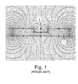
- Figure 1 is a schematic cross-sectional view of a magnetic field simulation taken from the above-mentioned International application which illustrates an example of a vertically magnetized permanent magnetic plate, designated by numerical reference 1, comprising a rectangular engraving 2.
- the engraved plate 1 is made of Plastoferrite (such as the Plastoferrite model M100.8 sold by Maurer Magnetic AG, CH-8627 Groningen, http://www.maurermagnetic.ch) magnetized in a direction perpendicular to the surface of the plate 1.
- Plastoferrite such as the Plastoferrite model M100.8 sold by Maurer Magnetic AG, CH-8627 Groningen, http://www.maurermagnetic.ch
- the field lines of the magnetic field are mostly vertical in the region of the surface of the body, except in the region of the vertical walls of the engraving 2. This implies that most of the magnetic pigments contained in the wet composition are aligned in a vertical manner, perpendicularly to the surface of the substrate. In other words, considering the fact that the pigments are mostly reflective when they are aligned substantially horizontally, the resulting pattern induced in the coating composition by means of the device of Figure 1 is mostly not reflective, when seen and illuminated perpendicularly to the surface of the substrate.
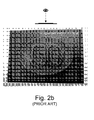
- Figures 2a to 2c are greyscale photographs, taken along three different viewing angles, of a magnetically-induced pattern representing the value "50" within an oval shape which was produced by means of a device according to the principle of International application WO 2005/002866 illustrated in Figure 1 . More precisely, the pattern was produced using a body having engravings representing the value "50" within an engraved oval shape.
- the layer of coating composition was applied with a silk-screen printing process on top of a black offset background using an OVI® silk-screen ink comprising gold-to-green optically variable magnetic pigment corresponding to the 7-layer pigment design disclosed in WO 02/73250 .
- the purpose of the black (or dark) offset background is to increase the contrast in the induced pattern by making the reflective parts of the pattern (i.e. the portions where the pigments are oriented substantially horizontally with respect to the surface of the substrate) stand out as compared to the less reflective parts of the pattern (i.e. the portions where the pigments are oriented substantially vertically with respect to the surface of the substrate, thereby revealing the underlying background).
- An aim of the invention is therefore to improve the known devices and methods for magnetically transferring indicia to a coating composition comprising magnetic or magnetizable particles
- a further aim of the present invention is to provide a device for magnetically transferring indicia to a coating composition comprising magnetic or magnetizable particles that is relatively easy and cheap to produce.
- Still another aim of the present invention is to provide a solution that increases the level of security of the resulting magnetically-induced pattern and makes it even more difficult to counterfeit.
- a device for magnetically transferring indicia to a layer of coating composition such as an ink or varnish, applied to at least a part of the surface of a substrate, the coating composition comprising at least one type of magnetic or magnetizable particles.
- the device comprises a body subjected to a magnetic field, which body carries determined indicia in the form of engravings on a surface of the body, which engravings influence the orientation of field lines of the magnetic field.
- the body further comprises at least one layer of material of high magnetic permeability in which the engravings are formed. In the absence of these engravings on the body, the field lines of the magnetic field extend substantially parallel to the surface of the body.
- the body further comprises a base plate of material of low magnetic permeability supporting the layer of material of high magnetic permeability.
- the layer of material of high magnetic permeability can advantageously be deposited on the base plate by galvanization.
- a preferred material for the base plate is a non-ferromagnetic material such as copper, aluminium or alloys thereof.
- the effect can be maximized when the engravings in the layer of material of high magnetic permeability extend through the whole thickness of the layer.
- the magnetic permeability of the layer of material of high magnetic permeability is selected to be greater than 100 ⁇ N/A 2 (@ 0.002 T), preferably between 100 to 1000 ⁇ N/A 2 (@ 0.002 T).
- a suitable material is a ferromagnetic material such as iron, nickel, cobalt or alloys thereof.
- the thickness of the layer of material of high magnetic permeability is preferably selected so as to be greater or equal to 50 microns, even more preferably between 50 to 500 microns.
- the magnetic field can advantageously be generated through electromagnetic means such as at least one permanent magnet or electromagnet, preferably two.
- electromagnetic means such as at least one permanent magnet or electromagnet, preferably two.
- other equivalent means susceptible of generating an electromagnetic field may also be used.
- the field lines of the magnetic field can extend along substantially one main direction parallel to the surface of the body.
- the device of the present invention can advantageously be shaped as a curved plate adapted for mounting onto a rotatable cylinder body of a printing press or as an individual curved plate element adapted for mounting onto a supporting member disposed on the circumference of a cylindrical body of a printing press.
- Also claimed is a method for magnetically transferring indicia onto a substrate, comprising the steps of :
- the coating composition is preferably applied by printing, even more preferably by silk-screen printing, flexographic printing or gravure printing.
- a printed document in particular a banknote, comprising a substrate with a coating composition applied to a least a part of a surface of the substrate and indicia magnetically-induced in the coating composition according to the above method.
- Yet another claimed object is the use of the above device for magnetically inducing transfer of indicia to a wet coating composition, such an ink or varnish, applied to at least a part of the surface of a substrate, which coating composition comprises at least one type of magnetic or magnetizable particles.
- Figure 3 is a schematic cross-sectional view of a magnetic-field-generating device, designated globally by reference numeral 10, according to a preferred embodiment of the present invention.
- the device 10 includes a body 20 the purpose of which is to influence the orientation of field lines of a magnetic field, as this will be explained hereinafter.
- the body 20 comprises a layer 21 made of material of high magnetic permeability in which engravings 21 a, 21 b, 21 c are formed, and a base plate 22 made of material of low magnetic permeability which supports the layer 21.
- FIG. 3 Also illustrated in Figure 3 is a sheet S disposed on top of the surface of the body 20 in contact with the upper surface of layer 21, which sheet S comprises a layer of coating composition P applied on the surface of the sheet S, opposite the surface of layer 21.
- Coating composition P comprises at least one type of magnetic or magnetizable particles, as discussed hereinabove, that one wishes to orient by means of the magnetic-field-generating device 10.
- the method for magnetically transferring indicia onto the substrate S comprises the steps of :
- a material of "high magnetic permeability” is a material that has the ability to concentrate the field lines of a magnetic field (i.e. is “magnetically attractable")
- a material of "low magnetic permeability” is a material that does not substantially affect the field lines of a magnetic field and behaves substantially like free space or vacuum.
- a material of "high magnetic permeability” is a material having a magnetic permeability p that is substantially greater than ⁇ 0 . More precisely, according to the present invention, material of high magnetic permeability will be understood as materials preferably exhibiting a magnetic permeability greater than 100 ⁇ N/A 2 (@ 0.002 T), even more preferably materials exhibiting a magnetic permeability between 100 to 1000 ⁇ N/A 2 (@ 0.002 T). It shall be understood that the magnetic permeability of materials varies with flux density. The above-mentioned values are therefore given considering a flux density of 0.002 T (hence the indication "@ 0.002 T" following the mentioned values).
- ferromagnetic materials such as iron, nickel, cobalt or alloys thereof (e.g. steel, permalloy, etc.).
- any material of high magnetic permeability is suitable. Tests have however shown that material exhibiting a magnetic permeability comprised between 100 to 1000 ⁇ N/A 2 (@ 0.002 T) are sufficient, and that materials exhibiting a magnetic permeability higher than 1000 ⁇ N/A 2 (@ 0.002 T), while also suitable, are not necessary.
- a particularly suitable material for layer 21 is nickel, which material has a magnetic permeability of approximately 125 ⁇ N/A 2 (@ 0.002 T).
- This material is convenient as it is commonly used in the banknote industry to produce intaglio printing plates, especially by galvanization, and is thus readily available to the banknote printer.
- This material is furthermore very easy to engrave (for instance mechanically by means of a rotating chisel or by means of gaseous or liquid jets of abrasives, by chemical etching, or even by laser ablation using CO 2 , Nd-YAG or excimer lasers).
- non-ferromagnetic materials such as copper, aluminium or alloys thereof.
- any material of low magnetic permeability is suitable. Glass or plastic could for instance be used as material for the base plate 22.
- the base plate 22 of material of low magnetic permeability is therefore not essential but preferred.
- a particularly suitable material for base plate 22 is copper, which material has a magnetic permeability of approximately 1.2566290 ⁇ N/A 2 . This material is also convenient as it is again commonly used in the banknote industry and is thus readily available to the banknote printer.
- a perfectly suitable alternative is aluminium which exhibits a magnetic permeability of approximately 1.2566650 ⁇ N/A 2 .
- the copper base plate 22 was approximately 0.5 mm thick and the nickel layer 21 was deposited by galvanization with layer thicknesses ranging from 50 to 500 microns.
- the magnetic field is generated in this example by a pair of permanent magnets 31, 32 (such as samarium-cobalt - SmCo - magnets as supplied by Maurer Magnetic AG) disposed at two ends I, II of the device 10.
- the permanent magnet 31 is disposed with its north magnetic pole oriented upwards
- the permanent magnet 32 is disposed with its north magnetic pole oriented downwards.
- the resulting magnetic field is such that field lines of the magnetic field will extend from the north magnetic pole of permanent magnet 31 at end I through the base plate 22, into layer 21, then substantially horizontally through, above and below the layer 21, from end I to end II, back through the base plate 22 and to the south magnetic pole of permanent magnet 32.
- the remainder of the magnetic circuit is closed through connection of the magnetic field lines at the lower part of the device, via the north magnetic pole of permanent magnet 32 and the south magnetic pole of permanent magnet 31. It will be appreciated that the same magnetic field configuration could alternatively be generated using electromagnets instead of the permanent magnets 31, 32.
- FIG. 4 A simulation of the resulting magnetic field distribution is shown schematically in Figure 4 .
- This simulation was produced using the publicly available modelling software Vizimag ( http://mvw.vonmag.com/ ) and considering a nickel layer as layer 21 and a copper base plate as base plate 22.
- the magnetic field lines would mostly be concentrated in the layer 21 itself, this layer 21 acting as a magnetic short-circuit.
- the engravings 21 a, 21 b, 21 c in the layer 21, which form in essence regions of low magnetic permeability (i.e. free space), force the magnetic field lines along different routes and orientations. In other words, the engravings 21a, 21b, 21c influence the orientation of the field lines of the magnetic field in the vicinity of the engravings 21 a, 21 b, 21 c.
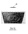
- Figures 5a to 5d are greyscale photographs taken from four different viewing angles of a magnetically induced pattern representing the value "50" within an oval shape, similar to the prior pattern illustrated in Figures 2a to 2c , but which was produced by means of a device according to the above-discussed preferred embodiment of the present invention.
- the body of the magnetic-field-generating device was engraved with exactly the same engraving pattern representing value "50" within an oval shape as that used for producing the prior pattern of Figures 2a to 2c .
- the above mentioned copper-nickel (Cu-Ni) body 20 was used.
- the resulting pattern is substantially more reflective and exhibits a radically different optical effect as compared to that illustrated in Figures 2a to 2c .
- the optical effect created according to the invention is more or less inverted as compared to the optical effect illustrated in Figures 2a to 2c .
- the oval shape appears to stand out in relief above the background, like a solid volume, with the value "50" looking like having been engraved into the solid oval shape.
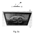
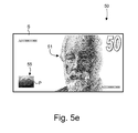
- Figure 5e is a schematic illustration of a possible banknote 50 comprising inter alia a portrait 51 and a magnetically-induced pattern 55 produced according to the present invention, such as the pattern of Figures 5a to 5d .
- the magnetic field lines are generally oriented along one main direction parallel to the surface of the body 20, that is along the direction I-II in Figures 3 and 4 .
- engraved lines in layer 21 oriented substantially parallel to this main direction I-II have a tendency to disappear or be attenuated in the resulting magnetically-induced pattern.
- Figures 5a to 5d one can in particular see that the side portions on the left-hand side and right-hand side of the oval shape are substantially attenuated.
- the engraved pattern so as to be devoid of engraved patterns extending along the main direction of the magnetic field lines and/or make the engraved pattern is such regions wide enough so as to cause a greater influence on the local orientation of the magnetic field lines.
- a solution might consist in changing the main direction of the magnetic field lines during exposure of the layer of coating composition P. This is preferably carried out by rotating, advantageously by 360°, the magnetic field with respect to the exposed layer of coating composition P.
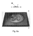
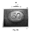
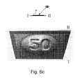
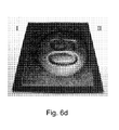
- Figures 6a to 6d are greyscale photographs taken along the same four different viewing angles as in Figures 5a to 5d of a magnetically-induced pattern representing the value "50" within an oval shape, identical to that of Figures 5a to 5d , with the additional provision that, during exposure of the layer of coating composition P, the main direction of the magnetic field lines was rotated by 360°.
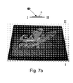
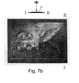
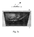
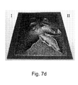
- Figures 7a to 7d are four photographs taken along the same four different viewing angles as those of Figures 5a to 5d and 6a to 6d , of another example of a magnetically-induced pattern.
- the main direction of the magnetic field was also rotated by 360° during exposure of the coating composition P.
- Figure 7e is a schematic top view of the engraved body 20 which was used in the context of the example shown in Figures 7a to 7d .
- the layer 21 of the body 20 was engraved with a pattern of engravings 211, 212 representing, on the one hand, a stylised representation of a Pegasus 211 and, on the other hand, the words "KBA GIORI" 212.
- the rectilinear or curvilinear patterns 211, 212 where engraved with a line width of approximately 1 millimeter. Tests have shown that a line width of 1 millimeter or more is preferable in the context of the present invention.
- too dense an engraving pattern is preferably to be avoided, i.e. a line spacing of 1 millimeter or more between neighbouring engravings is to be preferred.
- the thickness of layer 21 should be selected to be greater or equal to 50 microns, even more preferably in the range of 50 to 500 microns.
- the thickness of the base plate 22 on the other hand is not critical.
- the tests have shown that the distance between the permanent magnets 31, 32 and the body 20 had some influence on the resulting magnetically-induced pattern.
- the permanent magnets or, alternatively, the electromagnets
- the magnetic force of the magnets also plays a role.
- Electromagnets could be used in lieu of permanent magnets to create the necessary magnetic field. Electromagnets are particularly advantageous in that the magnetic field can be completely suppressed at the end of the exposure, thereby preventing further modification of the orientation of the magnetic or magnetizable particles, especially during removal of the substrate from the surface of the body 20.
- rotation of the main direction of the magnetic field can easily be carried out using electromagnets disposed in a circular arrangement and by electronically switching the orientation of the magnetic field in a manner similar to that performed in the context of the actuation of electric motors. Rotation of the magnetic field using permanent magnets would have to be performed by physical rotation of the permanent magnets themselves (or of the substrate S carrying the layer of coating composition P) during exposure.
- the above-described invention can be implemented by designing the above-described magnetic-field-generating device 10 so as to be disposed on the circumference of a cylindrical body of a printing press as generally taught in International application No. WO 2005/000585 in the name of the present Applicant.
- FIG 8 schematically illustrates one possible embodiment of a sheet-fed printing press as disclosed in International application No. WO 2005/000585 , which application is incorporated herein by reference.
- This printing press is adapted to print sheets according to the silk-screen printing process and comprises a feeding station 100 for feeding successive sheets to a silk-screen printing group 200 where silk-screen patterns are applied onto the sheets.
- the printing group 200 comprises an impression cylinder 200a cooperating with two screen cylinders 200b, 200c placed in succession along the printing path of the sheets.
- the freshly printed sheets are transported by means of a conveyor system 300 to a delivery station 400 comprising a plurality of delivery pile units, three in this example.
- the conveyor system 300 is typically an endless chain conveyor system comprising a plurality of spaced-apart gripper bars (not shown in Figure 8 ) extending transversely to the sheet transporting direction, each gripper bar comprising clamping means for holding a leading edge of the sheets.
- a cylinder body 600 carrying a plurality of magnetic-field-generating devices is located along the path of the sheets carried by the chain conveyor system 300.
- This cylinder body 600 is designed to apply a magnetic field to selected locations of the sheets for the purpose of orienting magnetic flakes contained in the patterns of coating composition which have been freshly-applied on the sheets in the printing group 200, as discussed above.
- a drying or curing unit 500 is provided downstream of the cylinder body 600 for drying, respectively curing, the coating composition applied onto the sheets after the magnetic flakes have been oriented and prior to the delivery in the delivery station 400, such unit 500 being typically an infrared drying unit or a UV curing unit depending on the type of coating composition used (e.g. water-based or UV-cured inks/varnishes).
- the cylinder body 600 could alternatively be located at the sheet transfer location 300a between the impression cylinder 200a and the conveyor system 300. Still according to another embodiment envisaged in International application No. WO 2005/000585 , the impression cylinder 200a itself could be designed as a cylinder carrying magnetic-field-generating devices.
- the cylinder body 600 used to orient the magnetic flakes advantageously cooperates with the non-freshly-printed side of the sheets, thereby preventing smearing problems, the magnetic field being applied from the back side of the sheets through the freshly-printed patterns of coating composition.
- the cylinder body 600 is rotated at a circumferential speed corresponding to the speed of the transported sheets so that there is no relative displacement between the transported sheets and the circumference of the cylinder.
- the cylinder body 600 is placed in the path of the chain conveyor system 300 such that the sheets follow a curved path tangential to the outer circumference of the cylinder body 600, thereby enabling part of the surface of the processed sheet to be brought in contact with the outer circumference of the cylinder body 600.
- each printed sheet (or each successive portion of a continuous web, in case of web-printing) carries an array of imprints arranged in a matrix of rows and columns, which imprints ultimately form individual securities after final cutting of the sheets or web portions.
- the cylinder body 600 used to orient the magnetic flakes is therefore typically provided with as many magnetic-field-generating devices as there are imprints on the sheets or web portions.
- the cylinder body 600 is preferably a cylinder body as further taught in European patent application No. 07102749.4 entitled "CYLINDER BODY FOR ORIENTING MAGNETIC FLAKES CONTAINED IN AN INK OR VARNISH VEHICLE PRINTED ON A SHEET-LIKE OR WEB-LIKE SUBSTRATE", filed on February 20, 2007 in the name of the present Applicant.
- the cylinder body advantageously comprises a plurality of distinct annular supporting rings distributed axially along a common shaft member, each annular supporting ring carrying a set of magnetic-field-generating devices which are distributed circumferentially on an outer circumference of the annular supporting rings. Thanks to this cylinder body configuration, the position of each magnetic-field-generating device can be adjusted to the corresponding position of the coating composition imprints on the processed sheets or web.
- the body 20 can be shaped as a curved plate adapted for mounting onto a rotatable cylinder body of a printing press (in such a case, a common plate with engravings could be used for all magnetic-field-generating devices) or, alternatively, as an individual curved plate element adapted for mounting onto a supporting member disposed on the circumference of a cylindrical body of a printing press (in such a case, individual plates would be used).
- the layer of coating composition P is preferably to be printed on a dark background
- any other background is possible such as for example a structured background as discussed in International application WO 2006/061301 .
- a mainly dark background is however preferred in order to yield a better contrast in the resulting magnetically-induced pattern.
Landscapes
- Physics & Mathematics (AREA)
- Engineering & Computer Science (AREA)
- Electromagnetism (AREA)
- Mechanical Engineering (AREA)
- Plasma & Fusion (AREA)
- Business, Economics & Management (AREA)
- Accounting & Taxation (AREA)
- Finance (AREA)
- Printing Methods (AREA)
- Credit Cards Or The Like (AREA)
Abstract
There is described a device (10) and method for magnetically transferring indicia to a coating composition (P), such as an ink or varnish, applied to at least a part of the surface of a substrate (S), the coating composition (P) comprising at least one type of magnetic or magnetizable particles. The device (10) comprises a body (20) subjected to a magnetic field generated by appropriate electromagnetic means, which body (20) carries determined indicia in the form of engravings (21a, 21b, 21c; 211, 212) on a surface of the body (20), which engravings (21a, 21b, 21c; 211, 212) influence orientation of field lines of the magnetic field. The body (20) comprises at least one layer (21) of material of high magnetic permeability in which the engravings (21a, 21 b, 21 c; 211, 212) are formed. In the absence of the engravings (21a, 21 b, 21c; 211, 212) on the body (20), the field lines of the magnetic field extend substantially parallel to the surface of the body (20).
Description
- The present invention generally relates to a device and method for magnetically transferring indicia to a coating composition, such as an ink or varnish, applied to at least a part of the surface of a substrate, which coating composition comprises magnetic or magnetizable particles. The present invention also relates to the use of such a device and the application of such a method to produce printed documents, such as banknotes or like valuable and security documents.
- Methods and devices for magnetically transferring indicia to a wet coating composition are already known as such in the art, for instance from International applications Nos.
WO 2004/007095 ,WO 2004/007096 ,WO 2005/000585 ,WO 2005/002866 andEP 1 650 042 - According to these methods, a layer of coating composition, such as an ink or varnish, is first applied to at least a part of the surface of a substrate, which coating composition comprises at least one type of magnetic or magnetizable particles. While the layer of coating composition is still wet, the layer is exposed to a determined magnetic field generated at a surface of a magnetic-field-generating device, thereby orienting the magnetic or magnetizable particles along field lines of the magnetic field. The layer of coating composition is then dried or cured, thereby fixing the orientation of the magnetic or magnetizable particles.
- Magnetic or magnetizable particles (also designated as "magnetic flakes"), which have the particularity that they can be oriented or aligned by an appropriately-applied magnetic field, are discussed in particular in US Patent No.
US 4,838,648 , European patent applicationEP 0 686 675 , and International applicationsWO 02/073250 WO 03/000801 WO 2004/007095 ,WO 2004/007096 andWO 2005/002866 . - Such particles or flakes are in particular used as optically-variable pigments in so-called optically-variable inks, or OVI®'s (OVI® is a registered trademark of SICPA Holding SA, Switzerland) to produce high-level security patterns, especially for banknotes.
- The most convenient method to apply the above magnetic flakes is by silk-screen printing as discussed in the above-mentioned International application
WO 2005/000585 . This is mainly due to the fact that the flakes have a relatively important size which restricts the choice of available printing processes for applying inks or varnishes containing such flakes. In particular, one has to ensure that the flakes are not destroyed or damaged during the printing process, and silk-screen printing constitutes the most convenient printing process to achieve this goal. Furthermore, silk-screen printing has the advantage that the inks or varnishes used in such a process exhibit a relatively low viscosity which favours proper orientation of the magnetic flakes. - Nevertheless, other printing processes could be envisaged to apply coating compositions containing magnetic flakes, such as flexographic printing or gravure printing. In European
patent application EP 1 650 042 , it is even proposed to apply such magnetic flakes in an intaglio printing process, whereby the paste-like intaglio ink containing the magnetic pigments is heated to decrease the viscosity of the ink and thereby allow the flakes to be oriented more easily with a magnetic or electric field. This can be performed in a conventional intaglio printing press, since the plate cylinder of such presses is commonly brought to an operating temperature of approximately 60 to 80 °C during printing operations. - Orientation of the magnetic flakes contained in the wet coating composition is carried out by applying an adequate magnetic field to the freshly-applied layer of coating composition. By appropriately shaping the field lines of the magnetic field, the magnetic flakes can be aligned in any desired pattern producing a corresponding optically-variable effect which is very difficult, if not impossible to counterfeit. An adequate solution for orienting the magnetic flakes, as discussed in International application
WO 2005/000585 consists in bringing sheets carrying layers of wet coating composition in contact with a rotating cylinder carrying a plurality of magnetic-field-generating devices. - International application
WO 2005/002866 , which is incorporated herein by reference, discloses a particular type of magnetic-field-generating device comprising a body, such as a flat plate or a cylindrically curved plate, made of a permanent magnetic material which is permanently magnetized in a direction substantially perpendicular to a surface of the body. The said surface of the body furthermore carries indicia in the form of engravings causing perturbations of its magnetic field. -
Figure 1 is a schematic cross-sectional view of a magnetic field simulation taken from the above-mentioned International application which illustrates an example of a vertically magnetized permanent magnetic plate, designated bynumerical reference 1, comprising arectangular engraving 2. In this example, the engravedplate 1 is made of Plastoferrite (such as the Plastoferrite model M100.8 sold by Maurer Magnetic AG, CH-8627 Groningen, http://www.maurermagnetic.ch) magnetized in a direction perpendicular to the surface of theplate 1. - As illustrated in
Figure 1 , as the permanentmagnetic body 1 is vertically magnetized, the field lines of the magnetic field are mostly vertical in the region of the surface of the body, except in the region of the vertical walls of theengraving 2. This implies that most of the magnetic pigments contained in the wet composition are aligned in a vertical manner, perpendicularly to the surface of the substrate. In other words, considering the fact that the pigments are mostly reflective when they are aligned substantially horizontally, the resulting pattern induced in the coating composition by means of the device ofFigure 1 is mostly not reflective, when seen and illuminated perpendicularly to the surface of the substrate. -
Figures 2a to 2c are greyscale photographs, taken along three different viewing angles, of a magnetically-induced pattern representing the value "50" within an oval shape which was produced by means of a device according to the principle of International applicationWO 2005/002866 illustrated inFigure 1 . More precisely, the pattern was produced using a body having engravings representing the value "50" within an engraved oval shape. - The layer of coating composition was applied with a silk-screen printing process on top of a black offset background using an OVI® silk-screen ink comprising gold-to-green optically variable magnetic pigment corresponding to the 7-layer pigment design disclosed in
WO 02/73250 - As already mentioned hereinabove, most part of the induced pattern produced according to the known method disclosed in International application
WO 2005/002866 is relatively dark, i.e. the pigments are mostly aligned vertically, thereby making the dark offset background visible through the layer of coating composition. As can be seen from the photographs ofFigures 2a to 2c , the most reflective portions of the magnetically-induced pattern correspond to the position of the walls of the engravings. Looking at the pattern, one basically has the impression that the oval shape and the value "50" stand out in relief above the background as illustrated inFigures 2a to 2c . - The patterns that can be produced according to the known method disclosed in International application
WO 2005/002866 discussed above are already quite an improvement as compared to the patterns that could previously be produced. A need has nevertheless arisen for an improved approach which would enable to produce different patterns, albeit with comparable means, especially patterns exhibiting a comparatively lighter, more reflective optical effect. - An aim of the invention is therefore to improve the known devices and methods for magnetically transferring indicia to a coating composition comprising magnetic or magnetizable particles
- A further aim of the present invention is to provide a device for magnetically transferring indicia to a coating composition comprising magnetic or magnetizable particles that is relatively easy and cheap to produce.
- Still another aim of the present invention is to provide a solution that increases the level of security of the resulting magnetically-induced pattern and makes it even more difficult to counterfeit.
- These aims are achieved thanks to the solution defined in the claims.
- According to the invention, there is accordingly proposed a device for magnetically transferring indicia to a layer of coating composition, such as an ink or varnish, applied to at least a part of the surface of a substrate, the coating composition comprising at least one type of magnetic or magnetizable particles. The device comprises a body subjected to a magnetic field, which body carries determined indicia in the form of engravings on a surface of the body, which engravings influence the orientation of field lines of the magnetic field. The body further comprises at least one layer of material of high magnetic permeability in which the engravings are formed. In the absence of these engravings on the body, the field lines of the magnetic field extend substantially parallel to the surface of the body.
- Thanks to this solution, a comparatively more reflective pattern can be created, which pattern moreover exhibits a radically different optical-effect than that of the prior art.
- According to a preferred embodiment, the body further comprises a base plate of material of low magnetic permeability supporting the layer of material of high magnetic permeability. In this context, the layer of material of high magnetic permeability can advantageously be deposited on the base plate by galvanization. Still in the context of this embodiment, the magnetic permeability of the base plate is preferably close to the magnetic permeability of vacuum µ0, where µ0 = 4TT 10-1 µN/A2. A preferred material for the base plate is a non-ferromagnetic material such as copper, aluminium or alloys thereof.
- The effect can be maximized when the engravings in the layer of material of high magnetic permeability extend through the whole thickness of the layer.
- According to an advantageous embodiment, the magnetic permeability of the layer of material of high magnetic permeability is selected to be greater than 100 µN/A2 (@ 0.002 T), preferably between 100 to 1000 µN/A2 (@ 0.002 T). In this context, a suitable material is a ferromagnetic material such as iron, nickel, cobalt or alloys thereof.
- The thickness of the layer of material of high magnetic permeability is preferably selected so as to be greater or equal to 50 microns, even more preferably between 50 to 500 microns.
- As regards the engravings in the layer of material of high magnetic permeability, those preferably comprise engraved rectilinear or curvilinear patterns having a line width and/or a line spacing of 1 millimeter or more.
- The magnetic field can advantageously be generated through electromagnetic means such as at least one permanent magnet or electromagnet, preferably two. Of course, other equivalent means susceptible of generating an electromagnetic field may also be used.
- The field lines of the magnetic field can extend along substantially one main direction parallel to the surface of the body. In this context, it is advantageous to change the main direction of the field lines of the magnetic field during exposure of the layer of coating composition. This change is preferably carried out by rotating the main direction of the magnetic field by 360°.
- The device of the present invention can advantageously be shaped as a curved plate adapted for mounting onto a rotatable cylinder body of a printing press or as an individual curved plate element adapted for mounting onto a supporting member disposed on the circumference of a cylindrical body of a printing press.
- Also claimed is a method for magnetically transferring indicia onto a substrate, comprising the steps of :
- (a) applying a layer of a coating composition, such as an ink or varnish, onto at least a part of the surface of the substrate, the coating composition comprising at least one type of magnetic or magnetizable particles;
- (b) while the layer of coating composition is still wet, exposing the layer of coating composition to a determined magnetic field generated at a surface of a device according to the invention, thereby orienting the magnetic or magnetizable particles along field lines of the magnetic field; and
- (c) drying or curing the layer of coating composition, thereby fixing the orientation of said magnetic or magnetizable particles.
- In the context of this method, the coating composition is preferably applied by printing, even more preferably by silk-screen printing, flexographic printing or gravure printing.
- Also claimed is a printed document, in particular a banknote, comprising a substrate with a coating composition applied to a least a part of a surface of the substrate and indicia magnetically-induced in the coating composition according to the above method.
- Yet another claimed object is the use of the above device for magnetically inducing transfer of indicia to a wet coating composition, such an ink or varnish, applied to at least a part of the surface of a substrate, which coating composition comprises at least one type of magnetic or magnetizable particles.
- Other features and advantages of the present invention will appear more clearly from reading the following detailed description of embodiments of the invention which are presented solely by way of non-restrictive examples and illustrated by the attached drawings in which:
-
Figure 1 is a schematic cross-sectional view of a magnetic field simulation taken from International applicationWO 2005/002866 mentioned hereinabove, which illustrates an example of a vertically-magnetized permanent magnetic plate comprising a rectangular engraving ; -
Figures 2a to 2c are three greyscale photographs taken along three different viewing angles of an example of magnetically-induced pattern produced according to the known principle disclosed inWO 2005/002866 ; -
Figure 3 is a schematic cross-sectional view of a magnetic-field-generating device according to a preferred embodiment of the present invention ; -
Figure 4 is a magnetic field simulation of the magnetic-field-generating device ofFigure 3 ; -
Figures 5a to 5d are four greyscale photographs taken along four different viewing angles of an example of magnetically-induced pattern produced according to the invention ; -
Figure 5e is a schematic illustration of a banknote comprising a magnetically-induced pattern as illustrated inFigures 5a to 5d ; -
Figures 6a to 6d are four greyscale photographs taken along four different viewing angles of an example of magnetically-induced pattern, similar to that shown inFigures 5a to 5c produced according to a variant of the invention ; -
Figures 7a to 7d are four greyscale photographs taken along four different viewing angles of another example of magnetically-induced pattern produced according to the invention ; -
Figure 7e is a schematic top view of the engraving pattern of the body used to produce the magnetically-induced pattern ofFigures 7a to 7d ; and -
Figure 8 is a schematic side view of a silk-screen printing press suitable for carrying out the invention. -
Figure 3 is a schematic cross-sectional view of a magnetic-field-generating device, designated globally byreference numeral 10, according to a preferred embodiment of the present invention. According to this embodiment, thedevice 10 includes abody 20 the purpose of which is to influence the orientation of field lines of a magnetic field, as this will be explained hereinafter. According to this preferred embodiment, thebody 20 comprises alayer 21 made of material of high magnetic permeability in whichengravings base plate 22 made of material of low magnetic permeability which supports thelayer 21. - Also illustrated in
Figure 3 is a sheet S disposed on top of the surface of thebody 20 in contact with the upper surface oflayer 21, which sheet S comprises a layer of coating composition P applied on the surface of the sheet S, opposite the surface oflayer 21. Coating composition P comprises at least one type of magnetic or magnetizable particles, as discussed hereinabove, that one wishes to orient by means of the magnetic-field-generatingdevice 10. - In the context of the present invention, one will understand that the method for magnetically transferring indicia onto the substrate S comprises the steps of :
- (a) applying the layer of coating composition P, such as an ink or varnish onto at least a part of the surface of the substrate S (the coating composition P comprising at least one type of magnetic or magnetizable particles such as those described in
WO 02/73250 - (b) while the layer of coating composition P is still wet, exposing the layer of coating composition P to a determined magnetic field generated at a surface of the
device 10 according to the present invention, thereby orienting the magnetic or magnetizable particles along field lines of the magnetic field ; and - (c) drying or curing the layer of coating composition P, thereby fixing the orientation of the magnetic or magnetizable particles.
- Within the scope of the present invention, it will be understood that a material of "high magnetic permeability" is a material that has the ability to concentrate the field lines of a magnetic field (i.e. is "magnetically attractable"), while a material of "low magnetic permeability" is a material that does not substantially affect the field lines of a magnetic field and behaves substantially like free space or vacuum. In other words, a material of "low magnetic permeability" will be understood as a material having a magnetic permeability µ close to µ0, where µ0 is commonly understood to be the magnetic permeability of vacuum and equals the following constant value (1) :

- In contrast, a material of "high magnetic permeability" is a material having a magnetic permeability p that is substantially greater than µ0. More precisely, according to the present invention, material of high magnetic permeability will be understood as materials preferably exhibiting a magnetic permeability greater than 100 µN/A2 (@ 0.002 T), even more preferably materials exhibiting a magnetic permeability between 100 to 1000 µN/A2 (@ 0.002 T). It shall be understood that the magnetic permeability of materials varies with flux density. The above-mentioned values are therefore given considering a flux density of 0.002 T (hence the indication "@ 0.002 T" following the mentioned values).
- Among materials of high magnetic permeability suitable for forming
layer 21, one in particular knows so-called ferromagnetic materials such as iron, nickel, cobalt or alloys thereof (e.g. steel, permalloy, etc.). Within the scope of the present invention, any material of high magnetic permeability is suitable. Tests have however shown that material exhibiting a magnetic permeability comprised between 100 to 1000 µN/A2 (@ 0.002 T) are sufficient, and that materials exhibiting a magnetic permeability higher than 1000 µN/A2 (@ 0.002 T), while also suitable, are not necessary. - A particularly suitable material for
layer 21 is nickel, which material has a magnetic permeability of approximately 125 µN/A2 (@ 0.002 T). This material is convenient as it is commonly used in the banknote industry to produce intaglio printing plates, especially by galvanization, and is thus readily available to the banknote printer. This material is furthermore very easy to engrave (for instance mechanically by means of a rotating chisel or by means of gaseous or liquid jets of abrasives, by chemical etching, or even by laser ablation using CO2, Nd-YAG or excimer lasers). - Among materials of low magnetic permeability suitable for forming
base plate 22, one in particular knows so-called non-ferromagnetic materials such as copper, aluminium or alloys thereof. Within the scope of the present invention, any material of low magnetic permeability is suitable. Glass or plastic could for instance be used as material for thebase plate 22. - According to an alternative of the invention, one could even do without the
base plate 22, for instance by making thelayer 21 self-supporting. Thebase plate 22 of material of low magnetic permeability is therefore not essential but preferred. - A particularly suitable material for
base plate 22 is copper, which material has a magnetic permeability of approximately 1.2566290 µN/A2. This material is also convenient as it is again commonly used in the banknote industry and is thus readily available to the banknote printer. A perfectly suitable alternative is aluminium which exhibits a magnetic permeability of approximately 1.2566650 µN/A2. - Successful tests have been carried out by the Applicant using a
copper base plate 22 and anickel layer 21 deposited on thecopper base plate 22 by galvanization. Thecopper base plate 22 was approximately 0.5 mm thick and thenickel layer 21 was deposited by galvanization with layer thicknesses ranging from 50 to 500 microns. - Turning back to the embodiment illustrated in
Figure 3 , the magnetic field is generated in this example by a pair ofpermanent magnets 31, 32 (such as samarium-cobalt - SmCo - magnets as supplied by Maurer Magnetic AG) disposed at two ends I, II of thedevice 10. As illustrated, thepermanent magnet 31 is disposed with its north magnetic pole oriented upwards, while thepermanent magnet 32 is disposed with its north magnetic pole oriented downwards. The resulting magnetic field is such that field lines of the magnetic field will extend from the north magnetic pole ofpermanent magnet 31 at end I through thebase plate 22, intolayer 21, then substantially horizontally through, above and below thelayer 21, from end I to end II, back through thebase plate 22 and to the south magnetic pole ofpermanent magnet 32. The remainder of the magnetic circuit is closed through connection of the magnetic field lines at the lower part of the device, via the north magnetic pole ofpermanent magnet 32 and the south magnetic pole ofpermanent magnet 31. It will be appreciated that the same magnetic field configuration could alternatively be generated using electromagnets instead of thepermanent magnets - A simulation of the resulting magnetic field distribution is shown schematically in
Figure 4 . This simulation was produced using the publicly available modelling software Vizimag (http://mvw.vizimag.com/) and considering a nickel layer aslayer 21 and a copper base plate asbase plate 22. - In the absence of any engravings in
layer 21, the magnetic field lines would mostly be concentrated in thelayer 21 itself, thislayer 21 acting as a magnetic short-circuit. Theengravings layer 21, which form in essence regions of low magnetic permeability (i.e. free space), force the magnetic field lines along different routes and orientations. In other words, theengravings engravings - As illustrated schematically in
Figure 4 , and in contrast to the prior solution disclosed in International applicationWO 2005/002866 (compare alsoFigure 4 andFigure 1 ), most of the magnetic field lines in the region of the sheet S and the coating composition P extend substantially horizontally rather than vertically as shown in the simulation offigure 1 . Consequently, a major part of the particles in the coating composition P will be aligned almost horizontally, yielding a generally more reflective pattern. - This difference is clearly demonstrated by
Figures 5a to 5d which are greyscale photographs taken from four different viewing angles of a magnetically induced pattern representing the value "50" within an oval shape, similar to the prior pattern illustrated inFigures 2a to 2c , but which was produced by means of a device according to the above-discussed preferred embodiment of the present invention. - More precisely, as far as the engravings are concerned, the body of the magnetic-field-generating device was engraved with exactly the same engraving pattern representing value "50" within an oval shape as that used for producing the prior pattern of
Figures 2a to 2c . Rather than using the vertically-magnetized Plastoferrite plate as proposed inWO 2005/002866 , the above mentioned copper-nickel (Cu-Ni)body 20 was used. - As illustrated in
Figures 5a to 5d , the resulting pattern is substantially more reflective and exhibits a radically different optical effect as compared to that illustrated inFigures 2a to 2c . Indeed, the optical effect created according to the invention is more or less inverted as compared to the optical effect illustrated inFigures 2a to 2c . More precisely, as illustrated inFigures 5a to 5d , the oval shape appears to stand out in relief above the background, like a solid volume, with the value "50" looking like having been engraved into the solid oval shape. -
Figure 5e is a schematic illustration of apossible banknote 50 comprising inter alia aportrait 51 and a magnetically-inducedpattern 55 produced according to the present invention, such as the pattern ofFigures 5a to 5d . - While performing tests using the above-described magnetic-field-generating
device 10, it has become apparent that the orientation of the engraved patterns on thebody 20 had some importance on the resulting effect. Indeed, in the preferred embodiment of the magnetic-field-generatingdevice 10 illustrated inFigures 3 and4 , the magnetic field lines are generally oriented along one main direction parallel to the surface of thebody 20, that is along the direction I-II inFigures 3 and4 . Accordingly, engraved lines inlayer 21 oriented substantially parallel to this main direction I-II have a tendency to disappear or be attenuated in the resulting magnetically-induced pattern. Looking for instance at the photographs ofFigures 5a to 5d , one can in particular see that the side portions on the left-hand side and right-hand side of the oval shape are substantially attenuated. - In order to overcome this effect, one could design the engraved pattern so as to be devoid of engraved patterns extending along the main direction of the magnetic field lines and/or make the engraved pattern is such regions wide enough so as to cause a greater influence on the local orientation of the magnetic field lines.
- Alternatively, a solution might consist in changing the main direction of the magnetic field lines during exposure of the layer of coating composition P. This is preferably carried out by rotating, advantageously by 360°, the magnetic field with respect to the exposed layer of coating composition P.
Figures 6a to 6d are greyscale photographs taken along the same four different viewing angles as inFigures 5a to 5d of a magnetically-induced pattern representing the value "50" within an oval shape, identical to that ofFigures 5a to 5d , with the additional provision that, during exposure of the layer of coating composition P, the main direction of the magnetic field lines was rotated by 360°. - As a result of the rotation of the magnetic field during exposure of the coating composition P, the above-mentioned attenuation effect is decreased or completely avoided. This rotation moreover appears to strengthen the embossing/relief effect on the resulting magnetically-induced pattern by making it visible in substantially the same way from all viewing angles, in the manner of a hologram. The difference is in particular visible from a comparison of the photographs of
Figures 5d and6d which are both taken from the same viewing angle, namely from the left-hand side of the coating composition P. -
Figures 7a to 7d are four photographs taken along the same four different viewing angles as those ofFigures 5a to 5d and6a to 6d , of another example of a magnetically-induced pattern. In this latter example, the main direction of the magnetic field was also rotated by 360° during exposure of the coating composition P. -
Figure 7e is a schematic top view of the engravedbody 20 which was used in the context of the example shown inFigures 7a to 7d . As illustrated, thelayer 21 of thebody 20 was engraved with a pattern ofengravings Pegasus 211 and, on the other hand, the words "KBA GIORI" 212. In this example, the rectilinear orcurvilinear patterns - Preferably, the thickness of
layer 21 should be selected to be greater or equal to 50 microns, even more preferably in the range of 50 to 500 microns. The thickness of thebase plate 22 on the other hand is not critical. - The tests have shown that the distance between the
permanent magnets body 20 had some influence on the resulting magnetically-induced pattern. Within the scope of the present invention, the permanent magnets (or, alternatively, the electromagnets) could be disposed at a distance from the body 20 (e.g. of the order of a few centimetres) or in close contact with thebody 20 depending on the effect one wishes to produce. In that respect, the magnetic force of the magnets also plays a role. - As already mentioned, electromagnets could be used in lieu of permanent magnets to create the necessary magnetic field. Electromagnets are particularly advantageous in that the magnetic field can be completely suppressed at the end of the exposure, thereby preventing further modification of the orientation of the magnetic or magnetizable particles, especially during removal of the substrate from the surface of the
body 20. In addition, rotation of the main direction of the magnetic field, as discussed above, can easily be carried out using electromagnets disposed in a circular arrangement and by electronically switching the orientation of the magnetic field in a manner similar to that performed in the context of the actuation of electric motors. Rotation of the magnetic field using permanent magnets would have to be performed by physical rotation of the permanent magnets themselves (or of the substrate S carrying the layer of coating composition P) during exposure. - The above-described invention can be implemented by designing the above-described magnetic-field-generating
device 10 so as to be disposed on the circumference of a cylindrical body of a printing press as generally taught in International application No.WO 2005/000585 in the name of the present Applicant. -
Figure 8 schematically illustrates one possible embodiment of a sheet-fed printing press as disclosed in International application No.WO 2005/000585 , which application is incorporated herein by reference. This printing press is adapted to print sheets according to the silk-screen printing process and comprises a feedingstation 100 for feeding successive sheets to a silk-screen printing group 200 where silk-screen patterns are applied onto the sheets. In this example theprinting group 200 comprises animpression cylinder 200a cooperating with twoscreen cylinders printing group 200, the freshly printed sheets are transported by means of aconveyor system 300 to adelivery station 400 comprising a plurality of delivery pile units, three in this example. Theconveyor system 300 is typically an endless chain conveyor system comprising a plurality of spaced-apart gripper bars (not shown inFigure 8 ) extending transversely to the sheet transporting direction, each gripper bar comprising clamping means for holding a leading edge of the sheets. - In the example illustrated in
Figure 8 , acylinder body 600 carrying a plurality of magnetic-field-generating devices is located along the path of the sheets carried by thechain conveyor system 300. Thiscylinder body 600 is designed to apply a magnetic field to selected locations of the sheets for the purpose of orienting magnetic flakes contained in the patterns of coating composition which have been freshly-applied on the sheets in theprinting group 200, as discussed above. A drying or curingunit 500 is provided downstream of thecylinder body 600 for drying, respectively curing, the coating composition applied onto the sheets after the magnetic flakes have been oriented and prior to the delivery in thedelivery station 400,such unit 500 being typically an infrared drying unit or a UV curing unit depending on the type of coating composition used (e.g. water-based or UV-cured inks/varnishes). - Further details regarding silk-screen printing presses, including relevant details of the silk-screen printing press illustrated in
Figure 8 , can be found in European patent applicationsEP 0 723 864 ,EP 0 769 376 and in International applicationsWO 97/29912 WO 97/34767 WO 03/093013 WO 2004/096545 ,WO 2005/095109 andWO 2005/102699 . - As discussed in International application No.
WO 2005/000585 , thecylinder body 600 could alternatively be located at thesheet transfer location 300a between theimpression cylinder 200a and theconveyor system 300. Still according to another embodiment envisaged in International application No.WO 2005/000585 , theimpression cylinder 200a itself could be designed as a cylinder carrying magnetic-field-generating devices. - In the embodiment illustrated in
Figure 8 , thecylinder body 600 used to orient the magnetic flakes advantageously cooperates with the non-freshly-printed side of the sheets, thereby preventing smearing problems, the magnetic field being applied from the back side of the sheets through the freshly-printed patterns of coating composition. During orientation of the magnetic flakes, i.e. at the time when a sheet carried by theconveyor system 300 contacts the upper part of the circumference of thecylinder body 600, thecylinder body 600 is rotated at a circumferential speed corresponding to the speed of the transported sheets so that there is no relative displacement between the transported sheets and the circumference of the cylinder. As illustrated, thecylinder body 600 is placed in the path of thechain conveyor system 300 such that the sheets follow a curved path tangential to the outer circumference of thecylinder body 600, thereby enabling part of the surface of the processed sheet to be brought in contact with the outer circumference of thecylinder body 600. - In the context of the production of banknotes, in particular, each printed sheet (or each successive portion of a continuous web, in case of web-printing) carries an array of imprints arranged in a matrix of rows and columns, which imprints ultimately form individual securities after final cutting of the sheets or web portions. The
cylinder body 600 used to orient the magnetic flakes is therefore typically provided with as many magnetic-field-generating devices as there are imprints on the sheets or web portions. - The
cylinder body 600 is preferably a cylinder body as further taught in European patent application No.07102749.4 - Turning back to the magnetic-field-generating devices according to the present invention, it will be appreciated that the
body 20 can be shaped as a curved plate adapted for mounting onto a rotatable cylinder body of a printing press (in such a case, a common plate with engravings could be used for all magnetic-field-generating devices) or, alternatively, as an individual curved plate element adapted for mounting onto a supporting member disposed on the circumference of a cylindrical body of a printing press (in such a case, individual plates would be used). - Various modifications and/or improvements may be made to the above-described embodiments without departing from the scope of the invention as defined by the annexed claims.
- For instance, while silk-screen printing is a preferred printing process for applying the coating composition comprising the magnetic or magnetizable particles to be oriented, other printing process might be envisaged, such as flexographic printing, gravure printing, or even intaglio printing as discussed in European
patent application EP 1 650 042 . - In addition, while the layer of coating composition P is preferably to be printed on a dark background, any other background is possible such as for example a structured background as discussed in International application
WO 2006/061301 . A mainly dark background is however preferred in order to yield a better contrast in the resulting magnetically-induced pattern.
Claims (20)
- A device (10) for magnetically transferring indicia to a layer of coating composition (P), such as an ink or varnish, applied to at least a part of the surface of a substrate (S), said coating composition (P) comprising at least one type of magnetic or magnetizable particles,
said device (10) comprising a body (20) subjected to a magnetic field generated by electromagnetic means, which body (20) carries determined indicia in the form of engravings (21 a, 21 b, 21 c; 211, 212) on a surface of the body (20), which engravings (21 a, 21 b, 21 c; 211, 212) influence orientation of field lines of the magnetic field,
wherein said body (20) comprises at least one layer (21) of material of high magnetic permeability in which said engravings (21a, 21b, 21c; 211, 212) are formed and wherein, in the absence of said engravings (21 a, 21 b, 21 c; 211, 212) on said body (20), the field lines of the magnetic field extend substantially parallel to the surface of said body (20). - The device according to claim 1, wherein said body (20) further comprises a base plate (22) of material of low magnetic permeability supporting said layer (21) of material of high magnetic permeability.
- The device according to claim 2, wherein said layer (21) of material of high magnetic permeability is deposited on said base plate (22) by galvanization.
- The device according to claim 2 or 3, wherein the magnetic permeability of said base plate (22) is close to the magnetic permeability of vacuum µ0 (µ0 = 4Π 10-1 µN/A2).
- The device according to claim 4, wherein said base plate (22) is made of a non-ferromagnetic material such as copper, aluminium or alloys thereof.
- The device according to any one of claims 1 to 5, wherein the engravings (21a, 21b, 21c; 211, 212) in said layer (21) of material of high magnetic permeability extend through the whole thickness of said layer (21).
- The device according to any one of claim 1 to 6, wherein the magnetic permeability of said layer (21) of material of high magnetic permeability is greater than 100 µN/A2 (@ 0.002 T), preferably between 100 to 1000 µN/A2 (@ 0.002 T).
- The device according to claim 7, wherein said layer (21) of material of high magnetic permeability is made of a ferromagnetic material such as iron, nickel, cobalt or alloys thereof.
- The device according to any one of the preceding claims, wherein said layer (21) of material of high magnetic permeability exhibits a thickness greater or equal to 50 microns, preferably between 50 to 500 microns.
- The device according to any one of the preceding claims, wherein said engravings (21a, 21b, 21c; 211, 212) comprise engraved rectilinear or curvilinear patterns (211, 212) preferably having a line width and/or a line spacing of 1 millimeter or more.
- The device according to any one of the preceding claims, comprising at least one permanent magnet (31, 32) as electromagnetic means.
- The device according to any one of claims 1 to 10, comprising at least one electromagnet as electromagnetic means.
- The device according to any one of the preceding claims, wherein the field lines of said magnetic field extend along substantially one main direction (I-II) parallel to the surface of the body (20).
- The device according to any one of the preceding claims, wherein said body (20) is shaped as a curved plate adapted for mounting onto a rotatable cylinder body (600) of a printing press.
- The device according to any one of claims 1 to 13, wherein said body (20) is shaped as an individual curved plate element adapted for mounting onto a supporting member disposed on the circumference of a cylindrical body (600) of a printing press.
- A method for magnetically transferring indicia onto a substrate (S), comprising the steps of :(a) applying a layer of a coating composition (P), such as an ink or varnish, onto at least a part of the surface of the substrate (S), said coating composition (P) comprising at least one type of magnetic or magnetizable particles;(b) while the layer of coating composition (P) is still wet, exposing the layer of coating composition (P) to a determined magnetic field generated at a surface of a device (10) according to any one of the preceding claims, thereby orienting the magnetic or magnetizable particles along field lines of said magnetic field; and(c) drying or curing the layer of coating composition (P), thereby fixing the orientation of said magnetic or magnetizable particles.
- The method according to claim 16, wherein the field lines of said magnetic field extend along substantially one main direction (I-II) parallel to the surface of the body (20) and wherein said main direction of the field lines of the magnetic field is changed, preferably rotated by 360°, during exposure of the layer of coating composition (P) at step (b).
- The method according to claim 16 or 17, wherein said coating composition is applied by printing, preferably by silk-screen printing, flexographic printing or gravure printing.
- Printed document (50), in particular banknote, comprising a substrate (S) with a coating composition (P, 55) applied to a least a part of a surface of said substrate (S) and indicia magnetically-induced in said coating composition (P, 55) according to the method of any one of claims 16 to 18.
- Use of the device according to any one of claims 1 to 15, for magnetically inducing transfer of indicia to a wet coating composition (P), such an ink or varnish, applied to at least a part of the surface of a substrate (S), which coating composition (P) comprises at least one type of magnetic or magnetizable particles.
Priority Applications (7)
| Application Number | Priority Date | Filing Date | Title |
|---|---|---|---|
| EP07107966A EP1990208A1 (en) | 2007-05-10 | 2007-05-10 | Device and method for magnetically transferring indica to a coating composition applied to a substrate |
| CN2008800236318A CN101743127B (en) | 2007-05-10 | 2008-05-07 | Device and method for magnetically transferring indicia to a coating composition applied to a substrate |
| US12/599,353 US8893614B2 (en) | 2007-05-10 | 2008-05-07 | Device and method for magnetically transferring indicia to a coating composition applied to a substrate |
| ES08738092.9T ES2472740T3 (en) | 2007-05-10 | 2008-05-07 | Device and method for magnetically transferring safety marks to a coating composition applied to a substrate |
| PCT/IB2008/051784 WO2008139373A1 (en) | 2007-05-10 | 2008-05-07 | Device and method for magnetically transferring indicia to a coating composition applied to a substrate |
| EP08738092.9A EP2155498B1 (en) | 2007-05-10 | 2008-05-07 | Device and method for magnetically transferring indicia to a coating composition applied to a substrate |
| JP2010507043A JP5547627B2 (en) | 2007-05-10 | 2008-05-07 | Apparatus and method for magnetically transferring a pattern to a coating composition applied to a substrate |
Applications Claiming Priority (1)
| Application Number | Priority Date | Filing Date | Title |
|---|---|---|---|
| EP07107966A EP1990208A1 (en) | 2007-05-10 | 2007-05-10 | Device and method for magnetically transferring indica to a coating composition applied to a substrate |
Publications (1)
| Publication Number | Publication Date |
|---|---|
| EP1990208A1 true EP1990208A1 (en) | 2008-11-12 |
Family
ID=38515858
Family Applications (2)
| Application Number | Title | Priority Date | Filing Date |
|---|---|---|---|
| EP07107966A Withdrawn EP1990208A1 (en) | 2007-05-10 | 2007-05-10 | Device and method for magnetically transferring indica to a coating composition applied to a substrate |
| EP08738092.9A Active EP2155498B1 (en) | 2007-05-10 | 2008-05-07 | Device and method for magnetically transferring indicia to a coating composition applied to a substrate |
Family Applications After (1)
| Application Number | Title | Priority Date | Filing Date |
|---|---|---|---|
| EP08738092.9A Active EP2155498B1 (en) | 2007-05-10 | 2008-05-07 | Device and method for magnetically transferring indicia to a coating composition applied to a substrate |
Country Status (6)
| Country | Link |
|---|---|
| US (1) | US8893614B2 (en) |
| EP (2) | EP1990208A1 (en) |
| JP (1) | JP5547627B2 (en) |
| CN (1) | CN101743127B (en) |
| ES (1) | ES2472740T3 (en) |
| WO (1) | WO2008139373A1 (en) |
Cited By (7)
| Publication number | Priority date | Publication date | Assignee | Title |
|---|---|---|---|---|
| EP2314386A1 (en) * | 2009-10-22 | 2011-04-27 | manroland AG | Coating method and device |
| WO2011092502A3 (en) * | 2010-02-01 | 2011-10-06 | De La Rue International Limited | Security elements and methods and apparatus for their manufacture |
| EP2548658A1 (en) * | 2011-07-21 | 2013-01-23 | Pago Etikettiersysteme GmbH | Magnetic printing method and device for performing the method |
| DE102014205638A1 (en) | 2013-03-27 | 2014-10-02 | Jds Uniphase Corp. | Optical device having an illusory optical effect and method of manufacture |
| CN107471818A (en) * | 2017-08-07 | 2017-12-15 | 甄欣 | The system that a kind of optomagnetic double fields form variable security pattern |
| WO2018019594A1 (en) * | 2016-07-29 | 2018-02-01 | Sicpa Holding Sa | Processes for producing effect layers |
| WO2018033512A1 (en) * | 2016-08-16 | 2018-02-22 | Sicpa Holding Sa | Processes for producing effects layers |
Families Citing this family (35)
| Publication number | Priority date | Publication date | Assignee | Title |
|---|---|---|---|---|
| ES2540864T3 (en) | 2010-09-24 | 2015-07-14 | Kba-Notasys Sa | System and method for orienting magnetic flakes or lamellae contained in an ink or varnish vehicle applied on a sheet-shaped or band-shaped substrate |
| CN102442097A (en) * | 2010-09-30 | 2012-05-09 | 王玉珠 | Magnetic printing method and printing product thereof |
| DK2468423T3 (en) * | 2010-12-27 | 2016-08-22 | Viavi Solutions Inc | System and method for forming an image on a substrate |
| CN103129195B (en) * | 2011-11-28 | 2016-05-25 | 珠海格力电器股份有限公司 | Magnetic ink printing method |
| CN104053552B (en) * | 2012-01-12 | 2017-07-25 | Viavi 科技有限公司 | The article of the bending pattern formed with the pigment flakes by arranging |
| FR2986181B1 (en) * | 2012-01-27 | 2014-02-21 | Oreal | METHOD FOR MAKING A DECORATION ON A MATERIAL SUPPORT FOR PRODUCING CASES FOR PACKAGING A COSMETIC PRODUCT |
| CN103386805B (en) * | 2012-05-09 | 2015-01-21 | 中国人民银行印制科学技术研究所 | Magnetic orientation roller |
| ES2831605T3 (en) | 2013-01-09 | 2021-06-09 | Sicpa Holding Sa | Optical effect layers showing an optical effect dependent on the angle of view, processes and devices for their production, articles provided with an optical effect layer and uses thereof |
| TW201431616A (en) * | 2013-01-09 | 2014-08-16 | Sicpa Holding Sa | Optical effect layers showing a viewing angle dependent optical effect; processes and devices for their production; items carrying an optical effect layer; and uses thereof |
| CN103303019A (en) * | 2013-06-26 | 2013-09-18 | 常熟印刷厂有限公司 | Printing method of magnetic publication |
| CN104442055B (en) * | 2014-11-27 | 2017-07-21 | 惠州市华阳光学技术有限公司 | The preparation method and its Preparation equipment of a kind of magnetic orientation pattern |
| CN106864014B (en) * | 2015-12-10 | 2020-02-28 | 惠州市华阳光学技术有限公司 | Magnet and magnetic orientation device |
| DE102015121822A1 (en) * | 2015-12-15 | 2017-06-22 | Bogen Electronic Gmbh | Information object and method for applying and reading the information of the object |
| AR107681A1 (en) | 2016-02-29 | 2018-05-23 | Sicpa Holding Sa | APPLIANCES AND PROCESSES TO PRODUCE LAYERS WITH OPTICAL EFFECT THAT INCLUDE MAGNETIC ORIENTED OR MAGNETIZABLE ORPHERIC PIGMENT PARTICLES |
| US10357991B2 (en) | 2016-12-19 | 2019-07-23 | Viavi Solutions Inc. | Security ink based security feature |
| DE102017202747B3 (en) | 2017-02-21 | 2018-08-16 | Koenig & Bauer Ag | Process for processing printing material sheets in the production of securities and securities printing machine |
| CN106965579A (en) * | 2017-03-20 | 2017-07-21 | 佛山市高明绿色德化工有限公司 | A kind of glass printing technique of fade effect |
| FR3067729B1 (en) * | 2017-06-19 | 2020-05-08 | Gerflor | PROCESS FOR PRODUCING A DECORATING LAYER HAVING A THREE-DIMENSIONAL ASPECT |
| TWI794359B (en) | 2018-01-17 | 2023-03-01 | 瑞士商西克帕控股有限公司 | Processes for producing optical effects layers |
| JP7362982B2 (en) | 2018-05-08 | 2023-10-18 | シクパ ホルディング ソシエテ アノニム | Magnetic assembly, apparatus, and process for producing optical effect layers containing non-spherically oriented magnetic or magnetizable pigment particles |
| DE102018004433A1 (en) * | 2018-06-05 | 2019-12-05 | Giesecke+Devrient Currency Technology Gmbh | Method for producing a value document, value document and printing device |
| EP3829891A1 (en) | 2018-07-30 | 2021-06-09 | Sicpa Holding SA | Assemblies and processes for producing optical effect layers comprising oriented magnetic or magnetizable pigment particles |
| AU2019313421A1 (en) | 2018-07-30 | 2021-03-18 | Sicpa Holding Sa | Processes for producing optical effects layers |
| CA3128938A1 (en) | 2019-02-08 | 2020-08-13 | Sicpa Holding Sa | Magnetic assemblies and processes for producing optical effect layers comprising oriented non-spherical oblate magnetic or magnetizable pigment particles |
| CN113631282B (en) | 2019-03-28 | 2023-03-31 | 锡克拜控股有限公司 | Magnetic assembly and method for producing an optical effect layer comprising oriented non-spherical magnetic or magnetizable pigment particles |
| WO2021083809A1 (en) | 2019-10-28 | 2021-05-06 | Sicpa Holding Sa | Magnetic assemblies and processes for producing optical effect layers comprising oriented non-spherical magnetic or magnetizable pigment particles |
| CN114616102B (en) | 2019-10-28 | 2024-02-20 | 锡克拜控股有限公司 | Magnetic assembly and method for producing an optical effect layer comprising oriented non-spherical magnetic or magnetizable pigment particles |
| CN110949029A (en) * | 2019-12-04 | 2020-04-03 | 云南侨通包装印刷有限公司 | Method for manufacturing layered magnetic light and color diffusion effect |
| AU2021295043A1 (en) | 2020-06-23 | 2023-02-16 | Sicpa Holding Sa | Methods for producing optical effect layers comprising magnetic or magnetizable pigment particles |
| CN111942060A (en) * | 2020-08-25 | 2020-11-17 | 彭亮 | Relief light variable anti-fake element |
| TW202239482A (en) | 2021-03-31 | 2022-10-16 | 瑞士商西克帕控股有限公司 | Methods for producing optical effect layers comprising magnetic or magnetizable pigment particles and exhibiting one or more indicia |
| WO2023161464A1 (en) | 2022-02-28 | 2023-08-31 | Sicpa Holding Sa | Methods for producing optical effect layers comprising magnetic or magnetizable pigment particles and exhibiting one or more indicia |
| CN114633574A (en) * | 2022-03-24 | 2022-06-17 | 彭亮 | Safety line or strip with dynamic visual three-dimensional effect |
| WO2024028408A1 (en) | 2022-08-05 | 2024-02-08 | Sicpa Holding Sa | Methods for producing optical effect layers comprising magnetic or magnetizable pigment particles and exhibiting one or more indicia |
| CN116393336B (en) * | 2023-06-09 | 2023-08-18 | 太原科技大学 | Clamp for spin coating of magnetostrictive material film substrate and using method thereof |
Citations (10)
| Publication number | Priority date | Publication date | Assignee | Title |
|---|---|---|---|---|
| US4838648A (en) | 1988-05-03 | 1989-06-13 | Optical Coating Laboratory, Inc. | Thin film structure having magnetic and color shifting properties |
| EP0686675A1 (en) | 1994-06-01 | 1995-12-13 | BASF Aktiengesellschaft | Magnetisable brilliant metallic pigments bearing multiple coatings |
| WO2002073250A2 (en) | 2001-03-09 | 2002-09-19 | Sicpa Holding S.A. | Magnetic thin film interference device or pigment and method of making it, printing ink or coating composition, security document and use of such a magnetic thin film interference device |
| WO2004007095A2 (en) | 2002-07-15 | 2004-01-22 | Jds Uniphase Corporation | Method and apparatus for orienting magnetic flakes and image obtained by said method |
| WO2004007096A2 (en) | 2002-07-15 | 2004-01-22 | Jds Uniphase Corporation | Magnetic planarization of pigment flakes |
| EP1493590A1 (en) * | 2003-07-03 | 2005-01-05 | Sicpa Holding S.A. | Method and means for producing a magnetically induced design in a coating containing magnetic particles |
| WO2005000585A1 (en) | 2003-06-30 | 2005-01-06 | Kba-Giori S.A. | Printing machine |
| EP1650042A1 (en) | 2004-10-20 | 2006-04-26 | JDS Uniphase Corporation | Method of alignment of magnetic particles in a paste-like ink, and the printing of optical effects |
| WO2006114289A1 (en) * | 2005-04-27 | 2006-11-02 | Leonhard Kurz Gmbh & Co. Kg | Method for the creation of color effect images |
| EP1787728A1 (en) * | 2005-11-18 | 2007-05-23 | JDS Uniphase Corporation | Magnetic plate for printing of optical effects |
Family Cites Families (26)
| Publication number | Priority date | Publication date | Assignee | Title |
|---|---|---|---|---|
| US4186944A (en) * | 1974-04-17 | 1980-02-05 | Emi Limited | Security document |
| JPS5656898A (en) * | 1979-10-15 | 1981-05-19 | Takeyoshi Yamaguchi | Printing method using magnetic force |
| JPS6168285A (en) * | 1984-09-12 | 1986-04-08 | Fuji Photo Film Co Ltd | Printing method |
| US5192611A (en) * | 1989-03-03 | 1993-03-09 | Kansai Paint Co., Ltd. | Patterned film forming laminated sheet |
| AU696709B2 (en) | 1995-01-24 | 1998-09-17 | Kba-Notasys Sa | Rotary screen printing machine for sheet printing |
| RU2157764C2 (en) | 1995-10-20 | 2000-10-20 | Де ля Рю Жиори С.А. | Sheet-fed machine |
| US5960716A (en) | 1996-02-19 | 1999-10-05 | De La Rue Giori, S.A. | Impression cylinder of a sheet-fed machine having grippers and a cover arranged in a cylinder pit |
| AU709046B2 (en) | 1996-03-21 | 1999-08-19 | Kba-Notasys Sa | Silk-screen printing machine |
| US6152035A (en) * | 1999-12-17 | 2000-11-28 | Universal Engraving, Inc. | Magnetic support plate for cladded steel and steel-backed polymer stamping/blocking and embossing graphic arts dies |
| US20020160194A1 (en) | 2001-04-27 | 2002-10-31 | Flex Products, Inc. | Multi-layered magnetic pigments and foils |
| CA2437028A1 (en) * | 2001-12-14 | 2003-06-26 | Meccanica Masi | Printing device for printing machines of various kind |
| DE10219845C1 (en) | 2002-05-03 | 2003-11-20 | Koenig & Bauer Ag | Screen printing machine and screen cylinder |
| EP1369230A1 (en) * | 2002-06-05 | 2003-12-10 | Kba-Giori S.A. | Method of manufacturing an engraved plate |
| US7934451B2 (en) * | 2002-07-15 | 2011-05-03 | Jds Uniphase Corporation | Apparatus for orienting magnetic flakes |
| EP1410923B1 (en) * | 2002-10-17 | 2006-08-09 | Hell Gravure Systems GmbH | Method for producing a printing plate for intaglio printing |
| JP2004209458A (en) * | 2002-11-12 | 2004-07-29 | Kansai Paint Co Ltd | Method for forming patterned coating film, and coated article |
| DE10319773B4 (en) | 2003-05-02 | 2006-04-20 | Koenig & Bauer Ag | screen printing cylinder |
| DE102004004713A1 (en) * | 2004-01-30 | 2005-09-01 | Leonhard Kurz Gmbh & Co. Kg | Security element with partial magnetic layer |
| EP1582349A1 (en) | 2004-03-30 | 2005-10-05 | Kba-Giori S.A. | Printing process and machine |
| EP1588850A1 (en) | 2004-04-22 | 2005-10-26 | Kba-Giori S.A. | Device for mounting and dismounting a doctor blade in a rotary screen printing cylinder |
| EP1669213A1 (en) | 2004-12-09 | 2006-06-14 | Sicpa Holding S.A. | Security element having a viewing-angle dependent aspect |
| TWI402106B (en) * | 2005-04-06 | 2013-07-21 | Jds Uniphase Corp | Dynamic appearance-changing optical devices (dacod) printed in a shaped magnetic field including printable fresnel structures |
| PL1745940T5 (en) * | 2005-07-20 | 2021-08-02 | Viavi Solutions Inc. | A two-step method of coating an article for security printing |
| NZ575677A (en) * | 2006-10-17 | 2011-01-28 | Sicpa Holding Sa | Method and means for producing a magnetically induced indicia in a coating containing magnetic particles |
| EP1961559A1 (en) * | 2007-02-20 | 2008-08-27 | Kba-Giori S.A. | Cylinder body for orienting magnetic flakes contained in an ink or varnish vehicle applied on a sheet-like or web-like substrate |
| EP2025515A1 (en) * | 2007-08-16 | 2009-02-18 | Kba-Giori S.A. | Screen printing press |
-
2007
- 2007-05-10 EP EP07107966A patent/EP1990208A1/en not_active Withdrawn
-
2008
- 2008-05-07 EP EP08738092.9A patent/EP2155498B1/en active Active
- 2008-05-07 ES ES08738092.9T patent/ES2472740T3/en active Active
- 2008-05-07 US US12/599,353 patent/US8893614B2/en active Active
- 2008-05-07 WO PCT/IB2008/051784 patent/WO2008139373A1/en active Application Filing
- 2008-05-07 CN CN2008800236318A patent/CN101743127B/en active Active
- 2008-05-07 JP JP2010507043A patent/JP5547627B2/en active Active
Patent Citations (12)
| Publication number | Priority date | Publication date | Assignee | Title |
|---|---|---|---|---|
| US4838648A (en) | 1988-05-03 | 1989-06-13 | Optical Coating Laboratory, Inc. | Thin film structure having magnetic and color shifting properties |
| EP0686675A1 (en) | 1994-06-01 | 1995-12-13 | BASF Aktiengesellschaft | Magnetisable brilliant metallic pigments bearing multiple coatings |
| WO2002073250A2 (en) | 2001-03-09 | 2002-09-19 | Sicpa Holding S.A. | Magnetic thin film interference device or pigment and method of making it, printing ink or coating composition, security document and use of such a magnetic thin film interference device |
| WO2004007095A2 (en) | 2002-07-15 | 2004-01-22 | Jds Uniphase Corporation | Method and apparatus for orienting magnetic flakes and image obtained by said method |
| WO2004007096A2 (en) | 2002-07-15 | 2004-01-22 | Jds Uniphase Corporation | Magnetic planarization of pigment flakes |
| WO2005000585A1 (en) | 2003-06-30 | 2005-01-06 | Kba-Giori S.A. | Printing machine |
| US20060219107A1 (en) * | 2003-06-30 | 2006-10-05 | Matthias Gygi | Printing machine |
| EP1493590A1 (en) * | 2003-07-03 | 2005-01-05 | Sicpa Holding S.A. | Method and means for producing a magnetically induced design in a coating containing magnetic particles |
| WO2005002866A1 (en) | 2003-07-03 | 2005-01-13 | Sicpa Holding S.A. | Method and means for producing a magnetically induced design in a coating containing magnetic particles |
| EP1650042A1 (en) | 2004-10-20 | 2006-04-26 | JDS Uniphase Corporation | Method of alignment of magnetic particles in a paste-like ink, and the printing of optical effects |
| WO2006114289A1 (en) * | 2005-04-27 | 2006-11-02 | Leonhard Kurz Gmbh & Co. Kg | Method for the creation of color effect images |
| EP1787728A1 (en) * | 2005-11-18 | 2007-05-23 | JDS Uniphase Corporation | Magnetic plate for printing of optical effects |
Cited By (22)
| Publication number | Priority date | Publication date | Assignee | Title |
|---|---|---|---|---|
| EP2314386A1 (en) * | 2009-10-22 | 2011-04-27 | manroland AG | Coating method and device |
| WO2011092502A3 (en) * | 2010-02-01 | 2011-10-06 | De La Rue International Limited | Security elements and methods and apparatus for their manufacture |
| CN102883891A (en) * | 2010-02-01 | 2013-01-16 | 德拉鲁国际有限公司 | Security elements and methods and apparatus for their manufacture |
| US9649871B2 (en) | 2010-02-01 | 2017-05-16 | De La Rue International Limited | Security elements, and methods and apparatus for their manufacture |
| AU2011210194B2 (en) * | 2010-02-01 | 2014-11-13 | De La Rue International Limited | Security elements and methods and apparatus for their manufacture |
| CN102883891B (en) * | 2010-02-01 | 2016-01-13 | 德拉鲁国际有限公司 | Safety element and the method and apparatus for the manufacture of safety element |
| US9248637B2 (en) | 2010-02-01 | 2016-02-02 | De La Rue International Limited | Security elements and methods and apparatus for their manufacture |
| AP3724A (en) * | 2010-02-01 | 2016-06-30 | Rue De Int Ltd | Security elements, and methods and apparatus for their manufacture |
| EA024086B1 (en) * | 2010-02-01 | 2016-08-31 | Де Ла Рю Интернешнл Лимитед | Security element, method and apparatus for its manufacture |
| EP2548658A1 (en) * | 2011-07-21 | 2013-01-23 | Pago Etikettiersysteme GmbH | Magnetic printing method and device for performing the method |
| US9579879B2 (en) | 2013-03-27 | 2017-02-28 | Viavi Solutions Inc. | Optical device having an illusive optical effect and method of fabrication |
| DE102014205638A1 (en) | 2013-03-27 | 2014-10-02 | Jds Uniphase Corp. | Optical device having an illusory optical effect and method of manufacture |
| US10029279B2 (en) | 2013-03-27 | 2018-07-24 | Viavi Solutions Inc. | Optical device having an illusive optical effect and method of fabrication |
| WO2018019594A1 (en) * | 2016-07-29 | 2018-02-01 | Sicpa Holding Sa | Processes for producing effect layers |
| CN109414722A (en) * | 2016-07-29 | 2019-03-01 | 锡克拜控股有限公司 | Method for line balancing rate layer |
| US10610888B2 (en) | 2016-07-29 | 2020-04-07 | Sicpa Holding Sa | Processes for producing effect layers |
| CN109414722B (en) * | 2016-07-29 | 2021-08-17 | 锡克拜控股有限公司 | Method for producing an effect layer |
| WO2018033512A1 (en) * | 2016-08-16 | 2018-02-22 | Sicpa Holding Sa | Processes for producing effects layers |
| US11292027B2 (en) | 2016-08-16 | 2022-04-05 | Sicpa Holding Sa | Processes for producing effect layers |
| US11707764B2 (en) | 2016-08-16 | 2023-07-25 | Sicpa Holding Sa | Processes for producing effect layers |
| CN107471818A (en) * | 2017-08-07 | 2017-12-15 | 甄欣 | The system that a kind of optomagnetic double fields form variable security pattern |
| CN107471818B (en) * | 2017-08-07 | 2023-06-13 | 甄欣 | System for forming variable safety pattern by using magneto-optical double fields |
Also Published As
| Publication number | Publication date |
|---|---|
| ES2472740T3 (en) | 2014-07-03 |
| WO2008139373A1 (en) | 2008-11-20 |
| JP2010526683A (en) | 2010-08-05 |
| EP2155498A1 (en) | 2010-02-24 |
| US8893614B2 (en) | 2014-11-25 |
| CN101743127B (en) | 2012-02-29 |
| US20110290129A1 (en) | 2011-12-01 |
| EP2155498B1 (en) | 2014-03-26 |
| JP5547627B2 (en) | 2014-07-16 |
| CN101743127A (en) | 2010-06-16 |
Similar Documents
| Publication | Publication Date | Title |
|---|---|---|
| EP1990208A1 (en) | Device and method for magnetically transferring indica to a coating composition applied to a substrate | |
| JP4941870B2 (en) | Method and means for making magnetically induced indicia in coatings containing magnetic particles | |
| KR101325406B1 (en) | Method and means for producing a magnetically induced design in a coating containing magnetic particles | |
| RU2738179C2 (en) | Methods of producing layers with effect | |
| EP3059019B1 (en) | Image obtained by a method for orienting magnetic flakes | |
| US8286551B2 (en) | Printing machine | |
| AU2011210194B2 (en) | Security elements and methods and apparatus for their manufacture | |
| EP2433798B1 (en) | System and method for orienting magnetic flakes contained in an ink or varnish vehicle applied on a sheet-like or web-like substrate | |
| AU2015200596B2 (en) | Security elements and methods and apparatus for their manufacture | |
| TH73153A (en) | Methods and pathways for the manufacture of patterns through magnetic induction into a coating containing magnetic particles. | |
| TH38276B (en) | Methods and pathways for the manufacture of patterns through magnetic induction into a coating containing magnetic particles. |
Legal Events
| Date | Code | Title | Description |
|---|---|---|---|
| PUAI | Public reference made under article 153(3) epc to a published international application that has entered the european phase |
Free format text: ORIGINAL CODE: 0009012 |
|
| AK | Designated contracting states |
Kind code of ref document: A1 Designated state(s): AT BE BG CH CY CZ DE DK EE ES FI FR GB GR HU IE IS IT LI LT LU LV MC MT NL PL PT RO SE SI SK TR |
|
| AX | Request for extension of the european patent |
Extension state: AL BA HR MK RS |
|
| AKX | Designation fees paid | ||
| REG | Reference to a national code |
Ref country code: DE Ref legal event code: 8566 |
|
| STAA | Information on the status of an ep patent application or granted ep patent |
Free format text: STATUS: THE APPLICATION IS DEEMED TO BE WITHDRAWN |
|
| 18D | Application deemed to be withdrawn |
Effective date: 20090513 |