EP1650042A1 - Method of alignment of magnetic particles in a paste-like ink, and the printing of optical effects - Google Patents
Method of alignment of magnetic particles in a paste-like ink, and the printing of optical effects Download PDFInfo
- Publication number
- EP1650042A1 EP1650042A1 EP05022781A EP05022781A EP1650042A1 EP 1650042 A1 EP1650042 A1 EP 1650042A1 EP 05022781 A EP05022781 A EP 05022781A EP 05022781 A EP05022781 A EP 05022781A EP 1650042 A1 EP1650042 A1 EP 1650042A1
- Authority
- EP
- European Patent Office
- Prior art keywords
- ink
- flakes
- paste
- printing
- magnetic
- Prior art date
- Legal status (The legal status is an assumption and is not a legal conclusion. Google has not performed a legal analysis and makes no representation as to the accuracy of the status listed.)
- Granted
Links
- 238000007639 printing Methods 0.000 title claims abstract description 66
- 238000000034 method Methods 0.000 title claims abstract description 52
- 230000003287 optical effect Effects 0.000 title description 7
- 239000006249 magnetic particle Substances 0.000 title description 5
- 230000005291 magnetic effect Effects 0.000 claims abstract description 80
- 239000000049 pigment Substances 0.000 claims description 21
- 239000000758 substrate Substances 0.000 claims description 19
- 230000008569 process Effects 0.000 claims description 18
- 238000010438 heat treatment Methods 0.000 claims description 11
- 230000005684 electric field Effects 0.000 claims description 10
- 230000000694 effects Effects 0.000 claims description 7
- 238000001035 drying Methods 0.000 claims description 6
- 230000003247 decreasing effect Effects 0.000 claims description 5
- 239000002904 solvent Substances 0.000 claims description 5
- 239000000463 material Substances 0.000 claims description 4
- 230000007704 transition Effects 0.000 claims description 3
- 238000010894 electron beam technology Methods 0.000 claims description 2
- 230000001678 irradiating effect Effects 0.000 claims 2
- 239000000976 ink Substances 0.000 abstract description 117
- 239000010409 thin film Substances 0.000 abstract 1
- 239000010410 layer Substances 0.000 description 13
- 239000003921 oil Substances 0.000 description 12
- 239000002245 particle Substances 0.000 description 9
- 239000003085 diluting agent Substances 0.000 description 6
- 238000010586 diagram Methods 0.000 description 5
- 239000012530 fluid Substances 0.000 description 5
- 238000001723 curing Methods 0.000 description 4
- 230000009467 reduction Effects 0.000 description 4
- 239000003570 air Substances 0.000 description 3
- 229910052782 aluminium Inorganic materials 0.000 description 2
- XAGFODPZIPBFFR-UHFFFAOYSA-N aluminium Chemical compound [Al] XAGFODPZIPBFFR-UHFFFAOYSA-N 0.000 description 2
- 230000008901 benefit Effects 0.000 description 2
- 229920000642 polymer Polymers 0.000 description 2
- 238000005096 rolling process Methods 0.000 description 2
- 239000000126 substance Substances 0.000 description 2
- IIEWJVIFRVWJOD-UHFFFAOYSA-N CCC1CCCCC1 Chemical compound CCC1CCCCC1 IIEWJVIFRVWJOD-UHFFFAOYSA-N 0.000 description 1
- 238000003848 UV Light-Curing Methods 0.000 description 1
- 239000012080 ambient air Substances 0.000 description 1
- 230000008859 change Effects 0.000 description 1
- 239000010634 clove oil Substances 0.000 description 1
- 230000001419 dependent effect Effects 0.000 description 1
- 230000004907 flux Effects 0.000 description 1
- 238000007646 gravure printing Methods 0.000 description 1
- 231100001261 hazardous Toxicity 0.000 description 1
- 238000003384 imaging method Methods 0.000 description 1
- 230000006698 induction Effects 0.000 description 1
- 238000007641 inkjet printing Methods 0.000 description 1
- 239000007788 liquid Substances 0.000 description 1
- 239000000696 magnetic material Substances 0.000 description 1
- 238000004519 manufacturing process Methods 0.000 description 1
- 229910052751 metal Inorganic materials 0.000 description 1
- 229910001172 neodymium magnet Inorganic materials 0.000 description 1
- 238000007645 offset printing Methods 0.000 description 1
- 230000001590 oxidative effect Effects 0.000 description 1
- 239000003973 paint Substances 0.000 description 1
- 230000005855 radiation Effects 0.000 description 1
- 239000011347 resin Substances 0.000 description 1
- 229920005989 resin Polymers 0.000 description 1
- 239000006254 rheological additive Substances 0.000 description 1
- 238000000926 separation method Methods 0.000 description 1
- 239000002356 single layer Substances 0.000 description 1
- 239000007787 solid Substances 0.000 description 1
- 238000011144 upstream manufacturing Methods 0.000 description 1
Images

Classifications
-
- B—PERFORMING OPERATIONS; TRANSPORTING
- B41—PRINTING; LINING MACHINES; TYPEWRITERS; STAMPS
- B41M—PRINTING, DUPLICATING, MARKING, OR COPYING PROCESSES; COLOUR PRINTING
- B41M3/00—Printing processes to produce particular kinds of printed work, e.g. patterns
-
- H—ELECTRICITY
- H01—ELECTRIC ELEMENTS
- H01F—MAGNETS; INDUCTANCES; TRANSFORMERS; SELECTION OF MATERIALS FOR THEIR MAGNETIC PROPERTIES
- H01F41/00—Apparatus or processes specially adapted for manufacturing or assembling magnets, inductances or transformers; Apparatus or processes specially adapted for manufacturing materials characterised by their magnetic properties
- H01F41/14—Apparatus or processes specially adapted for manufacturing or assembling magnets, inductances or transformers; Apparatus or processes specially adapted for manufacturing materials characterised by their magnetic properties for applying magnetic films to substrates
- H01F41/16—Apparatus or processes specially adapted for manufacturing or assembling magnets, inductances or transformers; Apparatus or processes specially adapted for manufacturing materials characterised by their magnetic properties for applying magnetic films to substrates the magnetic material being applied in the form of particles, e.g. by serigraphy, to form thick magnetic films or precursors therefor
-
- B—PERFORMING OPERATIONS; TRANSPORTING
- B41—PRINTING; LINING MACHINES; TYPEWRITERS; STAMPS
- B41M—PRINTING, DUPLICATING, MARKING, OR COPYING PROCESSES; COLOUR PRINTING
- B41M3/00—Printing processes to produce particular kinds of printed work, e.g. patterns
- B41M3/14—Security printing
- B41M3/144—Security printing using fluorescent, luminescent or iridescent effects
-
- C—CHEMISTRY; METALLURGY
- C09—DYES; PAINTS; POLISHES; NATURAL RESINS; ADHESIVES; COMPOSITIONS NOT OTHERWISE PROVIDED FOR; APPLICATIONS OF MATERIALS NOT OTHERWISE PROVIDED FOR
- C09D—COATING COMPOSITIONS, e.g. PAINTS, VARNISHES OR LACQUERS; FILLING PASTES; CHEMICAL PAINT OR INK REMOVERS; INKS; CORRECTING FLUIDS; WOODSTAINS; PASTES OR SOLIDS FOR COLOURING OR PRINTING; USE OF MATERIALS THEREFOR
- C09D11/00—Inks
- C09D11/02—Printing inks
- C09D11/03—Printing inks characterised by features other than the chemical nature of the binder
- C09D11/037—Printing inks characterised by features other than the chemical nature of the binder characterised by the pigment
-
- C—CHEMISTRY; METALLURGY
- C09—DYES; PAINTS; POLISHES; NATURAL RESINS; ADHESIVES; COMPOSITIONS NOT OTHERWISE PROVIDED FOR; APPLICATIONS OF MATERIALS NOT OTHERWISE PROVIDED FOR
- C09D—COATING COMPOSITIONS, e.g. PAINTS, VARNISHES OR LACQUERS; FILLING PASTES; CHEMICAL PAINT OR INK REMOVERS; INKS; CORRECTING FLUIDS; WOODSTAINS; PASTES OR SOLIDS FOR COLOURING OR PRINTING; USE OF MATERIALS THEREFOR
- C09D11/00—Inks
- C09D11/02—Printing inks
- C09D11/10—Printing inks based on artificial resins
- C09D11/101—Inks specially adapted for printing processes involving curing by wave energy or particle radiation, e.g. with UV-curing following the printing
-
- B—PERFORMING OPERATIONS; TRANSPORTING
- B41—PRINTING; LINING MACHINES; TYPEWRITERS; STAMPS
- B41M—PRINTING, DUPLICATING, MARKING, OR COPYING PROCESSES; COLOUR PRINTING
- B41M3/00—Printing processes to produce particular kinds of printed work, e.g. patterns
- B41M3/14—Security printing
Definitions
- This invention relates to a method and apparatus for orientating pigment particles dispersed in a highly viscous carrier such that the particles align and remain in a preferred orientation, and to images made by said method.
- Intaglio printing is a well known printing method using a printing plate having recesses formed in printing image areas with respect to non-printing image areas. After the entire intaglio printing plate is filled with a highly viscous ink, the ink on the non-printing image areas is wiped off to leave the ink only in the printing image areas. Thereafter, a web or substrate such as a paper sheet is forced directly to the printing plate under heavy pressure to transfer the ink remaining in the printing image areas onto the paper.
- Line-engraved intaglio printing is typically used for printing security documents, such as banknotes, and uses printing cylinders having engravings therein in which intaglio printing inks have been deposited.
- the highly viscous paste-like intaglio inks used in such printing are substantially different in nature from inks used in other forms of printing such as gravure, offset and ink-jet printing.
- attempts have been made to improve the dispersibility and chemical resistance of the paste-like intaglio inks; for example United States Patent 6,833,395 in the name of Rygas et al. assigned to the Canadian Bank Note Company, Limited (Ottawa, CA) attempts to provide a solution to this problem.
- Optically variable prints for other security documents and currencies are often printed on sheet-fed intaglio presses.
- the printing process involves enormous pressures (tons/sq-in) on the paper in the ink transfer from the plate, high press speeds (200 -500 ft/min), ultra viscous nature of the ink, and fast kinetics of the surface drying.
- Intaglio printing of security insignias is employed because of the unique properties that can be attained.
- the achievement of these special properties places strict requirements on the ink, the engraved plate, and the process conditions employed.
- the conventional steps of printing and curing and the new steps of aligning must still provide the same physical, chemical, and mechanical properties to the cured ink while at the same time enabling the accurate reproduction of the engraved image and predetermined position of magnetic particles.
- the concomitant requirements of stringently maintaining the correct visco-elastic properties of the paste-like ink while enabling a sequence of new and added steps to cause alignment of magnetic flakes presented a tremendous challenge to those skilled in the art.
- the achievement of printed and cured insignias encompassing magnetic flakes that have been aligned in a desired and predetermined manner requires a solution that overcomes a difficult set of constraints.
- the paste-like ink must be able to provide not only the normal drop and rise in viscosity that results from the printing step but must also be capable of surviving a second drop and rise in viscosity during the new alignment step.
- the second viscosity spike takes place after application of ink to substrate rather than in the fluid state.
- the printed but uncured ink must provide this viscosity drop-rise quickly so as not to slow down the line speed of the press.
- the magnetic flakes must orient quickly in the dwell time provided by the magnet apparatus-sometimes in less than one second. Once in the desired position, the flakes must freeze in place and avoid the natural relaxation that will occur unless the proper steps are followed. This fixing of the flake position must be permanent and must survive the lifetime of the security document - a period of years in the case of a circulating banknote.
- the process is additionally constrained.
- the energy when energy is applied to the ink to reduce viscosity, the energy must be applied in a manner and with an amplitude sufficient to cause the desired change to the ink without damaging the materials involved with the process.
- the heat or other energy must not scorch or damage the ink or the substrate - usually paper or polymer.
- the added energy must not damage the printing press.
- the type of energy must be compatible with the mechanical hardware in the alignment zone. For example, application of microwave energy to a press zone containing metallic elements could be hazardous.
- a method of printing and aligning special effect flakes such that at least some of the printed flakes orient along field lines of an applied field comprising the steps of:
- a method of printing and aligning special effect flakes such that at least some of the printed flakes orient along field lines of an applied field comprising the steps of:
- a product is formed wherein flakes are reoriented in a predetermined manner using a magnetic field or electric field and wherein the viscosity of the ink is lessened by adding energy to the ink during the time when the flakes are reoriented or immediately before the time when the flakes are reoriented.
- pigment flakes are printed on a substrate and oriented using an intaglio process and a magnetic alignment process wherein the intaglio ink having magnetically orientable flakes therein, undergoes a transition and is made less viscous during the alignment process than it is prior to be printed.
- viscous paste-like ink is applied through a conventional printing process and a step of adding energy to the ink, such as thermal energy after printing or during printing to lessen the viscosity of the ink, so that magnetic flakes within the ink can be oriented in a magnetic or electric field along field lines.
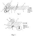
- Fig. 1 is a schematic diagram illustrating an intaglio printing process in accordance with an embodiment of the invention, wherein a magnetic field is disposed adjacent a print roller and wherein a heat source is provided to temporarily lessen the viscosity of the ink prior to alignment of flakes within the ink.
- Fig. 2 is a schematic diagram similar to that of Fig. 1 wherein magnets for providing a magnetic field for aligning flakes within the past like viscous ink are provided within an impression roller.
- Fig. 3 is a schematic diagram similar to that of Fig. 1 wherein a UV curing source is provided directly over the flake alignment magnets.
- Fig. 4 is a schematic diagram similar to Fig. 3, wherein a heat source is provided directly over the alignment magnets.
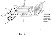
- Fig. 5 is a schematic diagram similar to that of Fig. 2 wherein a sheet of paper 4 is printed between the rollers wherein a printed image moves to the magnetic stage having heating elements adjacent thereto.
- the paste-like viscous ink preferably comprises flakes of optical interference pigment, or flakes of a reflective pigment, or single layer or multi layer diffractive pigment flakes having magnetic properties.
- This invention similarly lends itself to any alignment method wherein flakes can be aligned in a preferred orientation using any forces that are practicable. For example, particles movable in electric fields that can force the special effect flakes in a desired orientation, may benefit from this invention, wherein paste-like printing inks having flakes therein can be temporarily made less viscous during alignment.
- the interference pigment is an optically variable pigment that contains a thin layer of magnetic material surrounded by an aluminum layer as well as a thin layer of dielectric separating the magnetic layer from the aluminum.
- the pigment is dispersed in a high-viscosity carrier that may contain additional solvents or a cure retarder to keep the ink layer fluid during transition of the print through the magnetic zone; preferably in the range of 4-40 Pa ⁇ s at the temperature of 40°C or more.
- Printing of the image with magnetic paste-like ink occurs in the press where magnets are either embedded into the impression cylinder or located as close to the impression cylinders as possible.
- the ideal environment for an illusionary optical effect, generated in an applied magnetic field is the one that maximizes the dwell time of a "fluid" ink layer in a region of high magnetic flux concentration, coupled with a vehicle system that has the correct visco-elastic properties to allow for magnetically permeable flakes to orient during the time spent in the magnetic zone.
- the printing press is equipped with magnetic hardware for providing an illusionary optical effect.
- illusionary optical effects are achieved by alignment of flakes dispersed in a liquid ink vehicle along lines of an applied magnetic field in a predetermined, varying manner, for example such that some of the flakes are purposely oriented differently than others. For example, some flakes may be standing on their edges, while others may be lying flat, and, or, some flakes may be tilted to varying degrees between flat lying and edge standing flakes.
- the hardware is placed directly down the web as is shown in Fig.1 and as close to the printing and impression cylinders as possible.
- Sheets of freshly printed optically variable ink are conveyed over the magnetic lines, with a vertical separation between the magnet surface and the ink surface no greater than about 1 inch.
- the freshly deposited ink is either still fluid enough after the application of sufficient heat energy to allow the magnetic pigment particles, dispersed in the ink vehicle, to align themselves parallel to the applied field lines or, alternatively, the paste-like viscous ink is heated so as to be re-fluidized immediately before the magnetic hardware.
- printing roller 1 has number of engravings 2 in the shape of a desired image on the printing plate wrapping the roller.
- Printing roller 1 and impression roller 3 touch each other and rotate in opposite directions.
- a web in the form of a sheet of paper 4, inserted between the rollers, moves from the left to the right.
- the web could alternatively take the form of a continuous roll of paper, film, or polymer.
- the image 5 shown in the picture is a solid filled rectangle.
- the previously printed sheet of paper 8 moves over the top of linear magnetic assembly 6 with permanent magnets 7 immediately after completion of the printing. Designs of hardware for linear magnetic effects had been described in the aforementioned patents.
- the ink In order for the magnetic orientation steps to be compatible with the high-speed printing process characteristics, it is advantageous for the ink to contain either additional or slower drying solvents to keep the ink layer fluid during transit through the magnetic zone. If printing roller 1 is also heated to lessen the viscosity of the paste-like ink, these slower drying solvents are formulated to contain fewer light fractions that "flash off", allowing more solvent to remain in the deposited layer. Utilization of a cure retarder, such as clove oil and others, provides additional methods to prevent the ink surface from skinning over prior to the sheet reaching the magnet apparatus.
- a cure retarder such as clove oil and others
- Viscosity of the paste like ink measured at 25°C and 50°C, depends on content of the oil and the temperature as shown below: Diluent % Diluent Viscosity at 25°C and shear rate of 5.7 s -1 Viscosity at 50°C and shear rate of 5.7 s -1 1 g Flash Oil 9.1% 64 32 1.5 g Flash Oil 13.0% 44 25
- Viscosity of diluted and non-diluted inks was mixed with a optically-variable pigment and diluted with oil. Viscosity of diluted and non-diluted inks, measured at 25°C and 40°C, depends on content of the oil and the temperature as shown below: Resin Pigment Diluent % Diluent Viscosity at 25°C and shear rate of 5.7 s -1 Viscosity at 40°C and shear rate of 5.7 s -1 7.15 g 2.5g none 0.0% 200 in the range of 50 -80 8.41 g 2.95 g 0.6 g 500 Oil 5.0% 130 58
- a non-magnetic printing cylinder 10 that includes image engravings 12, is heated to lessen the viscosity of the ink during the printing step.
- the non-magnetic impression roller 13 creates enormous nip pressures onto the non-magnetic printing cylinder 10 during the ink transfer.
- the impression cylinder 13 includes a series of embedded magnets 14 with polarity 16 at prescribed intervals matching the engraving pattern 12 and repeat of the cylinder 10. Both cylinders rotate in opposite directions. Sheet of paper 15 is fed between the cylinders causing the image 17 to be transferred from the engravings onto the paper the moment when both cylinders are in the nearest contact with each other.
- the surfaces of the magnetic elements 14 are coincident with the recessed engravings of the image engravings 12.
- the magnetic field emanating from each element 14 interacts with the magnetic pigment particles in the ink causing re-orientation of the particles along the lines of the applied magnetic field.
- the printed image 17 already has a magnetic illusionary effect of a rolling bar. Since the dwell times of ink in the magnetic field envisioned in this embodiment are considerably shorter than the previously described embodiment of Fig. 1, additional rheology modifiers may be needed to balance a drop in viscosity while maintaining proper tack without affecting the ink split characteristics.
- Fig. 3 a similar configuration to that of Fig. 1 is shown, however the printing press is slightly different and is designed for printing of magnetic UV-curable optically variable ink.
- a sheet of paper 4 is printed between the rollers 1 and 3 and moves to the magnetic stage 7.
- the ink maintains some flow ability when it reaches the magnetic field.
- magnetic particles align themselves along magnetic lines in the field on the top of the magnetic stage.
- a UV light source or electron beam unit 11 is mounted opposite to the alignment magnets and is switched on after the flakes are aligned.
- the UV light source can be positioned near the magnetic stage 7.
- UV-curable ink can also be used in the embodiment of Fig. 2, by positioning a UV light source so to cure the ink immediately after the ink splits from the engraving.
- FIG. 4 Another embdoiment displayed in Fig. 4 is simlar to that of Fig.1.
- heat energy is applied to the ink and to the paper when they are located over the magnets rather than at the printing rollers.
- the heat source 13 is installed downstream of the rollers and is oriented so as to be facing the magnetic field.
- the energy source 13 heats the printed element reducing the ink viscosity sufficiently such that the flakes are able to align following lines of the magnetic field.
- energy transfer can be accomplished via radiation, conduction or convection. Heat transfer may be provided with steam, hot air, infrared irradiation, microwave, radio frequency induction, light energy or any other suitable method. By way of example infrared (IR) irradiation may be used.
- IR infrared
- the essential aspect of this invention is that the energy acts to lessen the viscosity of the paste-like printing ink, so that the ink is compatible with a flake alignment process such as magnetic field alignment of magnetically alignable flakes.
- FIG. 5 Another embodiment displayed in Fig. 5 is simlar to that of Fig.4.
- a sheet of paper 4 is printed between the rollers 1 and 3 and moves to the magnetic stage 7.
- Heating elements 14 are mounted above the magnetic stage 7 at the distance from 0.0625" to 1.5".
- the elements 14 heat the paper and the ink to reduce the ink viscosity to the level providing alignment of magnetic particles in the field of the stage 7.
- the elements 14 are usually longer that the stage 7 because they need to start to heat the ink before it comes to the stage 7.
- the UV-light source 13 is installed shortly after magnetic stage 7 in order to fix position of already aligned particles in the volume of the ink and to cure the ink vehicle.
Abstract
Description
- This invention relates to a method and apparatus for orientating pigment particles dispersed in a highly viscous carrier such that the particles align and remain in a preferred orientation, and to images made by said method.
- Intaglio printing is a well known printing method using a printing plate having recesses formed in printing image areas with respect to non-printing image areas. After the entire intaglio printing plate is filled with a highly viscous ink, the ink on the non-printing image areas is wiped off to leave the ink only in the printing image areas. Thereafter, a web or substrate such as a paper sheet is forced directly to the printing plate under heavy pressure to transfer the ink remaining in the printing image areas onto the paper. Line-engraved intaglio printing is typically used for printing security documents, such as banknotes, and uses printing cylinders having engravings therein in which intaglio printing inks have been deposited. The highly viscous paste-like intaglio inks used in such printing are substantially different in nature from inks used in other forms of printing such as gravure, offset and ink-jet printing. To varying degrees of success, attempts have been made to improve the dispersibility and chemical resistance of the paste-like intaglio inks; for example United States Patent 6,833,395 in the name of Rygas et al. assigned to the Canadian Bank Note Company, Limited (Ottawa, CA) attempts to provide a solution to this problem.
- Another United States patent that relates to enhancements within an intaglio printed image and suggesting the addition of dielectric flakes within the intaglio ink, is US patent 6,815,065, in the name of Argoitia et al., assigned to Flex Products Inc, incorporated herein by reference. The '065 patent discloses drawing down ink or paint which generally flattens the pigment flakes in the plane of the surface of the substrate.
- As of late there has been considerable interest in obtaining special affects by magnetically orienting magnetic flakes, that is, flakes that will align in a magnetic field, in a predetermined manner, to follow the field lines. Examples are found in United States patent 6,902,807 in the names of Argoitia et al., entitled Alignable diffractive pigment flakes, and United States patent 6,808,806 in the names of Phillips et al., entitled Methods for producing imaged coated articles by using magnetic pigments; Phillips et al., disclose orienting magnetically orientable flakes in applied magnetic fields to achieve special affects; both of these patents are incorporated herein by reference.
- Printing of secure labels and valuable documents with illusive optical effects based on utilization of low-viscosity magnetic optically variable flexo and silk-screen inks, is described in details in US Patent Application 20040051297 assigned to Flex Products Inc., is incorporated herein by reference.
- Optically variable prints for other security documents and currencies are often printed on sheet-fed intaglio presses. The printing process involves enormous pressures (tons/sq-in) on the paper in the ink transfer from the plate, high press speeds (200 -500 ft/min), ultra viscous nature of the ink, and fast kinetics of the surface drying.
- Intaglio printing of security insignias is employed because of the unique properties that can be attained. The achievement of these special properties places strict requirements on the ink, the engraved plate, and the process conditions employed. For example, after completion of printing the ink must maintain a specific morphology and configuration i.e. separate islands or strings that accurately replicate the fine detail of the parent engraving. Therefore, the conventional steps of printing and curing and the new steps of aligning must still provide the same physical, chemical, and mechanical properties to the cured ink while at the same time enabling the accurate reproduction of the engraved image and predetermined position of magnetic particles. The concomitant requirements of stringently maintaining the correct visco-elastic properties of the paste-like ink while enabling a sequence of new and added steps to cause alignment of magnetic flakes presented a tremendous challenge to those skilled in the art.
- The achievement of printed and cured insignias encompassing magnetic flakes that have been aligned in a desired and predetermined manner requires a solution that overcomes a difficult set of constraints. For example, the paste-like ink must be able to provide not only the normal drop and rise in viscosity that results from the printing step but must also be capable of surviving a second drop and rise in viscosity during the new alignment step. Complicating matters, the second viscosity spike takes place after application of ink to substrate rather than in the fluid state. To support high-speed printing, the printed but uncured ink must provide this viscosity drop-rise quickly so as not to slow down the line speed of the press. In the high-speed example, the magnetic flakes must orient quickly in the dwell time provided by the magnet apparatus-sometimes in less than one second. Once in the desired position, the flakes must freeze in place and avoid the natural relaxation that will occur unless the proper steps are followed. This fixing of the flake position must be permanent and must survive the lifetime of the security document - a period of years in the case of a circulating banknote.
- Besides requirements placed on the ink, the magnets, and the magnetic flakes, the process is additionally constrained. For example, when energy is applied to the ink to reduce viscosity, the energy must be applied in a manner and with an amplitude sufficient to cause the desired change to the ink without damaging the materials involved with the process. For example, the heat or other energy must not scorch or damage the ink or the substrate - usually paper or polymer. The added energy must not damage the printing press. The type of energy must be compatible with the mechanical hardware in the alignment zone. For example, application of microwave energy to a press zone containing metallic elements could be hazardous.
- Thus, when one attempts printing using thick, highly viscous paste-like inks having magnetic flakes or particles therein, alignment of these flakes using standard intaglio-like processes and inks is less than satisfactory as the high-viscosity of the paste-like ink prevents the magnetically alignable flakes from moving and reorienting within the carrier; therefore, heretofore, alignment using an applied magnetic field with highly viscous paste-like inks has not been practicable.
- It is therefore an object of this invention to provide a method and apparatus that will allow these highly viscous paste-like inks to be utilized in the printing of special effect pigments wherein the pigments can be aligned in preferred orientations using a magnetic field so as to yield desired illusionary affects.
- It is a further object of this invention to provide magnetically orientable flakes fixedly oriented in a preferred orientation wherein the flakes are initially disposed in a paste-like ink having a viscosity of at least 100-200 Pa·s when the ambient temperature is in a range of 15-30 degrees C.
- According to the present invention, the above objects are achieved by a method of printing and aligning special effect flakes as defined by
independent claim 1 and independent claims 18 and 19. The dependent claims define preferred and advantageous embodiments of the invention. - In accordance with this invention there is provided, a method of printing and aligning special effect flakes such that at least some of the printed flakes orient along field lines of an applied field, the method comprising the steps of:
- a) providing a paste-like ink, which has a viscosity V of at least 100 Pa·s when at a temperature of between 15 and 25 degrees C, wherein the paste-like ink is comprised of a carrier having flakes therein and wherein the flakes are comprised of at least a layer of magnetically orientable material;
- b) applying the paste like ink by printing said ink upon a substrate;
- c) decreasing the viscosity V of the paste-like ink by at least 60 % for at least a time sufficient for applying a magnetic or electric field to the printed ink, so as to allow the flakes to align within the paste-like ink along field lines of the electric or magnetic field; and,
- d) applying a magnetic or electric field to the printed ink to align the flakes.
- In accordance with the invention there is provided a method of printing and aligning special effect flakes such that at least some of the printed flakes orient along field lines of an applied field, the method comprising the steps of:
- a) providing a paste-like ink having a viscosity V at an ambient temperature, wherein the paste-like ink is comprised of carrier having flakes therein and wherein the flakes are comprised of at least a layer of magnetically orientable material;
- b) applying the paste like ink by printing said ink upon a substrate;
- c) decreasing the viscosity V of the paste-like ink substantially and by a sufficient amount, for at least a time sufficient for applying a magnetic or electric field to the printed ink, so as to allow the flakes to align within the paste-like ink along field lines of the electric or magnetic field; and,
- d) applying a magnetic or electric field to the printed ink to align the flakes.
- In accordance with the invention, a product is formed wherein flakes are reoriented in a predetermined manner using a magnetic field or electric field and wherein the viscosity of the ink is lessened by adding energy to the ink during the time when the flakes are reoriented or immediately before the time when the flakes are reoriented.
- In accordance with the invention, pigment flakes are printed on a substrate and oriented using an intaglio process and a magnetic alignment process wherein the intaglio ink having magnetically orientable flakes therein, undergoes a transition and is made less viscous during the alignment process than it is prior to be printed.
- In accordance with this invention, viscous paste-like ink is applied through a conventional printing process and a step of adding energy to the ink, such as thermal energy after printing or during printing to lessen the viscosity of the ink, so that magnetic flakes within the ink can be oriented in a magnetic or electric field along field lines.
- The invention will now be described in detail with reference to preferred embodiments shown in the drawings.
- Fig. 1 is a schematic diagram illustrating an intaglio printing process in accordance with an embodiment of the invention, wherein a magnetic field is disposed adjacent a print roller and wherein a heat source is provided to temporarily lessen the viscosity of the ink prior to alignment of flakes within the ink.
- Fig. 2 is a schematic diagram similar to that of Fig. 1 wherein magnets for providing a magnetic field for aligning flakes within the past like viscous ink are provided within an impression roller.
- Fig. 3 is a schematic diagram similar to that of Fig. 1 wherein a UV curing source is provided directly over the flake alignment magnets.
- Fig. 4 is a schematic diagram similar to Fig. 3, wherein a heat source is provided directly over the alignment magnets.
- Fig. 5 is a schematic diagram similar to that of Fig. 2 wherein a sheet of
paper 4 is printed between the rollers wherein a printed image moves to the magnetic stage having heating elements adjacent thereto. - For printing of securities and high-value documents a novel process is provided, which allows paste-like ink having magnetic platelets or flakes dispersed therein to be oriented in a magnetic field. The paste-like viscous ink preferably comprises flakes of optical interference pigment, or flakes of a reflective pigment, or single layer or multi layer diffractive pigment flakes having magnetic properties. This invention similarly lends itself to any alignment method wherein flakes can be aligned in a preferred orientation using any forces that are practicable. For example, particles movable in electric fields that can force the special effect flakes in a desired orientation, may benefit from this invention, wherein paste-like printing inks having flakes therein can be temporarily made less viscous during alignment.
- In one example, the interference pigment is an optically variable pigment that contains a thin layer of magnetic material surrounded by an aluminum layer as well as a thin layer of dielectric separating the magnetic layer from the aluminum. The pigment is dispersed in a high-viscosity carrier that may contain additional solvents or a cure retarder to keep the ink layer fluid during transition of the print through the magnetic zone; preferably in the range of 4-40 Pa·s at the temperature of 40°C or more. Printing of the image with magnetic paste-like ink occurs in the press where magnets are either embedded into the impression cylinder or located as close to the impression cylinders as possible.
- Conceptually, the ideal environment for an illusionary optical effect, generated in an applied magnetic field, is the one that maximizes the dwell time of a "fluid" ink layer in a region of high magnetic flux concentration, coupled with a vehicle system that has the correct visco-elastic properties to allow for magnetically permeable flakes to orient during the time spent in the magnetic zone.
- In a first embodiment of this invention, the printing press is equipped with magnetic hardware for providing an illusionary optical effect. Typically, illusionary optical effects are achieved by alignment of flakes dispersed in a liquid ink vehicle along lines of an applied magnetic field in a predetermined, varying manner, for example such that some of the flakes are purposely oriented differently than others. For example, some flakes may be standing on their edges, while others may be lying flat, and, or, some flakes may be tilted to varying degrees between flat lying and edge standing flakes. The hardware is placed directly down the web as is shown in Fig.1 and as close to the printing and impression cylinders as possible. Sheets of freshly printed optically variable ink are conveyed over the magnetic lines, with a vertical separation between the magnet surface and the ink surface no greater than about 1 inch. The freshly deposited ink is either still fluid enough after the application of sufficient heat energy to allow the magnetic pigment particles, dispersed in the ink vehicle, to align themselves parallel to the applied field lines or, alternatively, the paste-like viscous ink is heated so as to be re-fluidized immediately before the magnetic hardware.
- In Fig. 1
printing roller 1 has number ofengravings 2 in the shape of a desired image on the printing plate wrapping the roller.Printing roller 1 andimpression roller 3 touch each other and rotate in opposite directions. A web in the form of a sheet ofpaper 4, inserted between the rollers, moves from the left to the right. The web could alternatively take the form of a continuous roll of paper, film, or polymer. The moment when the paper is positioned exactly between the rollers, an engraving holding the paste-like ink comes to this point and the ink is transferred onto the paper forming printedimage 5. Theimage 5 shown in the picture is a solid filled rectangle. The previously printed sheet ofpaper 8 moves over the top of linear magnetic assembly 6 withpermanent magnets 7 immediately after completion of the printing. Designs of hardware for linear magnetic effects had been described in the aforementioned patents. - According to these patents and applications, when passed through the field, the magnetic particles become aligned in the direction of the lines of a magnetic field. As a result, in one example a linear "rolling bar"
optical effect 9 appears in the print. This is shown and described in United States Patent application 20050106367, in the name of Raksha et al., filed December 22, 2004 incorporated herein by reference. - Referring once again to Fig. 1, as printed sheets of, for example, banknotes are rapidly conveyed from the
impression cylinder 3 to a stacking unit, the sheets are exposed to high volumes of ambient air. One result of this air is to affect an almost immediate surface drying reaction. From the time optically variable ink is printed to the time the sheets are stacked, which is generally less than one minute, the ink viscosity increases rapidly, and the sheets can be stacked without offsetting. It is preferred that this print-to-stack duration be held below 5 minutes to minimize the number of sheets in transit. - In order for the magnetic orientation steps to be compatible with the high-speed printing process characteristics, it is advantageous for the ink to contain either additional or slower drying solvents to keep the ink layer fluid during transit through the magnetic zone. If
printing roller 1 is also heated to lessen the viscosity of the paste-like ink, these slower drying solvents are formulated to contain fewer light fractions that "flash off", allowing more solvent to remain in the deposited layer. Utilization of a cure retarder, such as clove oil and others, provides additional methods to prevent the ink surface from skinning over prior to the sheet reaching the magnet apparatus. - The three examples below and accompanying tables, clearly show the benefit of adding oil and simultaneously adding thermal energy in the form of heat to lessen the viscosity of the ink while applying the magnetic field.
- 7.25g of paste-like ink vehicle by
Supplier # 1 was mixed with 2.5g of optically-variable pigment and diluted with Flash Oil in two different concentrations. Viscosity of the paste like ink, measured at two different temperatures, depends on content of the oil and the temperature as shown below:Diluent % Diluent Viscosity at 25°C and shear rate of 5.7 s-1 Viscosity at 50 C and shear rate of 5.7 s-1 1g Flash Oil 9.3% 62 8 1.5 g Flash Oil 13.3% 43 8 - 7.5 g of viscous paste-like ink vehicle by
Supplier # 2 was mixed with 2.5g of optically-variable pigment and diluted with Flash Oil in two different concentrations. Viscosity of the paste like ink, measured at 25°C and 50°C, depends on content of the oil and the temperature as shown below:Diluent % Diluent Viscosity at 25°C and shear rate of 5.7 s-1 Viscosity at 50°C and shear rate of 5.7 s-1 1 g Flash Oil 9.1% 64 32 1.5 g Flash Oil 13.0% 44 25 - A viscous paste-like ink vehicle by
Supplier # 2 was mixed with a optically-variable pigment and diluted with oil. Viscosity of diluted and non-diluted inks, measured at 25°C and 40°C, depends on content of the oil and the temperature as shown below:Resin Pigment Diluent % Diluent Viscosity at 25°C and shear rate of 5.7 s-1 Viscosity at 40°C and shear rate of 5.7 s-1 7.15 g 2.5g none 0.0% 200 in the range of 50 -80 8.41 g 2.95 g 0.6 g 500 Oil 5.0% 130 58 - In a second embodiment shown in Fig. 2, the steps of ink transfer and magnetic imaging occur almost simultaneously. Again, a
non-magnetic printing cylinder 10, that includesimage engravings 12, is heated to lessen the viscosity of the ink during the printing step. Thenon-magnetic impression roller 13 creates enormous nip pressures onto thenon-magnetic printing cylinder 10 during the ink transfer. Theimpression cylinder 13 includes a series of embeddedmagnets 14 with polarity 16 at prescribed intervals matching theengraving pattern 12 and repeat of thecylinder 10. Both cylinders rotate in opposite directions. Sheet ofpaper 15 is fed between the cylinders causing theimage 17 to be transferred from the engravings onto the paper the moment when both cylinders are in the nearest contact with each other. At the precise moment of ink transfer, the surfaces of themagnetic elements 14 are coincident with the recessed engravings of theimage engravings 12. As the ink layer splits from the engraving, the magnetic field emanating from eachelement 14 interacts with the magnetic pigment particles in the ink causing re-orientation of the particles along the lines of the applied magnetic field. As a result of the re-orientation and alignment, the printedimage 17 already has a magnetic illusionary effect of a rolling bar. Since the dwell times of ink in the magnetic field envisioned in this embodiment are considerably shorter than the previously described embodiment of Fig. 1, additional rheology modifiers may be needed to balance a drop in viscosity while maintaining proper tack without affecting the ink split characteristics. - Referring now to Fig. 3, a similar configuration to that of Fig. 1 is shown, however the printing press is slightly different and is designed for printing of magnetic UV-curable optically variable ink. Similar to Fig. 1, a sheet of
paper 4 is printed between therollers magnetic stage 7. In accordance with this invention, the ink maintains some flow ability when it reaches the magnetic field. Within the ink, magnetic particles align themselves along magnetic lines in the field on the top of the magnetic stage. In order to freeze the magnetic flakes while still in the magnetic field, a UV light source orelectron beam unit 11 is mounted opposite to the alignment magnets and is switched on after the flakes are aligned. Alternatively, the UV light source can be positioned near themagnetic stage 7. As the substrate continues to move, it arrives at the curing zone of the curingsource 11 and the ink solidifies fixing the magnetic flakes in the preferred tilted position in dependence upon the field lines. It should be appreciated that UV-curable ink can also be used in the embodiment of Fig. 2, by positioning a UV light source so to cure the ink immediately after the ink splits from the engraving. - Another embdoiment displayed in Fig. 4 is simlar to that of Fig.1. In Fig. 4 heat energy is applied to the ink and to the paper when they are located over the magnets rather than at the printing rollers. The
heat source 13 is installed downstream of the rollers and is oriented so as to be facing the magnetic field. - The
energy source 13 heats the printed element reducing the ink viscosity sufficiently such that the flakes are able to align following lines of the magnetic field. Of course various means of supplying energy are possible. Energy transfer can be accomplished via radiation, conduction or convection. Heat transfer may be provided with steam, hot air, infrared irradiation, microwave, radio frequency induction, light energy or any other suitable method. By way of example infrared (IR) irradiation may be used. The essential aspect of this invention is that the energy acts to lessen the viscosity of the paste-like printing ink, so that the ink is compatible with a flake alignment process such as magnetic field alignment of magnetically alignable flakes. - Employing an embodiment similar to that shown in Figure 4, convection was used as the method of viscosity reduction to facilitate flake alignment. In this example, a multi-step process was employed for the production of printed sheets:
- A paste-like oxidative-cure ink was prepared that incorporated particles of optically variable interference pigment containing a magnetic layer.
- The ink was applied to high-quality bond paper sheet substrates using an engraved plate and a laboratory Intaglio press.
- The printed paper sheets were transported singly on a conveyor system at speeds between 50 and 200 ft/min.
- Air heated to approximately 300 degrees C was directed at the printed sheet at the position just upstream of the magnets in order to cause a reduction of viscosity in the ink more than 60%.
- Immediately after the application of heat, the uncured ink passed over a line of NdFeB magnets of dimension 4.0 inches x 1.5 inches x 0.25 inches. The line of magnets included two of these 4.0" long magnets oriented lengthwise to provide a total length of 8.0 inches in the direction of travel. Exposure of the printed image having ink of reduced viscosity to the magnetic field caused alignment of the flakes into an arched pattern running down the length of the image.
- The printed sheets were carried by the conveyor out of the heat and magnet zones in order for the oxidative curing to take place.
- Although in the previous example, a 60% reduction in viscosity was sufficient to allow alignment of the flakes in the field, in other instances depending upon the viscosity of the ink, a reduction of viscosity of more than 80% is preferable.
- Another embodiment displayed in Fig. 5 is simlar to that of Fig.4.
- Referring now to Fig. 5, a sheet of
paper 4 is printed between therollers magnetic stage 7.Heating elements 14 are mounted above themagnetic stage 7 at the distance from 0.0625" to 1.5". Theelements 14 heat the paper and the ink to reduce the ink viscosity to the level providing alignment of magnetic particles in the field of thestage 7. Theelements 14 are usually longer that thestage 7 because they need to start to heat the ink before it comes to thestage 7. The UV-light source 13 is installed shortly aftermagnetic stage 7 in order to fix position of already aligned particles in the volume of the ink and to cure the ink vehicle. - Of course numerous other embodiments may be envisaged, without departing from the spirit and scope of the invention.
Claims (19)
- A method of printing and aligning special effect flakes such that at least some of the printed flakes orient along field lines of an applied field, the method comprising the steps of:a) providing a paste-like ink, which has a viscosity V of at least 100 Pa·s when at a temperature of between 15 and 25 degrees C, wherein the paste-like ink is comprised of a carrier having flakes therein and wherein the flakes are comprised of at least a layer of magnetically orientable material;b) applying the paste like ink by printing said ink upon a substrate (4);c) decreasing the viscosity V of the paste-like ink by at least 60 % for at least a time sufficient for applying a magnetic or electric field to the printed ink, so as to allow the flakes to align within the paste-like ink along field lines of the electric or magnetic field; and,d) applying a magnetic or electric field to the printed ink to align the flakes.
- A method as defined in claim 1, wherein in step (c) the viscosity V is decreased by at least 80%.
- A method as defined in claim 1 or claim 2, wherein the step of decreasing the viscosity V of the paste-like ink comprises the step of heating the paste-like ink after or during step (b).
- A method as defined in claim 3, wherein the step of heating includes passing the substrate (4) along a heated roller (1; 10).
- A method as defined in claim 3 or claim 4, wherein the step of heating the paste-like ink is performed by heating the substrate (4).
- A method as defined in any one of claims 3-5, wherein the ink is printed on the substrate (4) using a printing roller (10) and an impression roller (13) and wherein the step of heating is performed by heating at least one of the printing roller (10) and the impression roller (13), and wherein the impression roller has magnets (14) imbedded therein, for providing the magnetic field.
- A method as defined in claim 3, wherein the ink is printed on the substrate (4) using a printing roller (1) and an impression roller (3) and wherein the step of heating is performed by applying heat downstream from the printing roller (1).
- A method as defined in claim 3 or claim 7, wherein the step of heating includes passing the substrate (4) along a heated element (13, 14).
- A method as defined in claim 3, wherein step (b) is an intaglio printing process and wherein the paste-like ink is an intaglio ink having said flakes therein.
- A method as defined in any one of claims 1-9, wherein the viscosity of the paste-like ink is lessened after printing the ink on the substrate (4), proximate to where the printing occurs.
- A method as defined in any one of claims 1-10 further comprising a step (e) of curing the magnetic flakes after they have been aligned in step (d).
- A method as defined in claim 11, wherein the curing step involves a first portion of less than 5 minutes in which surface drying occurs followed by a second portion in which the subsurface cures.
- A method as defined in claim 11 or claim 12, wherein the step of curing includes irradiation the ink with UV light or ebeam right after a heating of the ink.
- A method as defined in any one of claims 11-13, wherein the step of curing includes the step of irradiating the ink with UV light.
- A method as defined in claim 11 or claim 12, wherein the step of curing includes the step of irradiating the ink with electron beam.
- A method as defined in any one of claims 1-15, wherein the paste-like ink includes slow drying solvents and/or a cure retarder
- An image formed on the substrate made by the method of any one of claims 1-16.
- An image printed on a substrate (4), said image comprising flakes within an ink vehicle, wherein the flakes have been reoriented in a predetermined manner using a magnetic or electric field and wherein the viscosity of the ink was lessened by adding energy to the ink during the time when the flakes were reoriented or immediately before a time when the flakes were reoriented.
- An image comprising pigment flakes in an intaglio ink printed on a substrate (4) using an intaglio printing process and oriented by a magnetic alignment process wherein the intaglio ink has undergone a transition so as to lessen its viscosity during the alignment process.
Priority Applications (1)
| Application Number | Priority Date | Filing Date | Title |
|---|---|---|---|
| PL05022781T PL1650042T3 (en) | 2004-10-20 | 2005-10-19 | Method of alignment of magnetic particles in a paste-like ink, and the printing of optical effects |
Applications Claiming Priority (2)
| Application Number | Priority Date | Filing Date | Title |
|---|---|---|---|
| US62047104P | 2004-10-20 | 2004-10-20 | |
| US63346304P | 2004-12-06 | 2004-12-06 |
Publications (2)
| Publication Number | Publication Date |
|---|---|
| EP1650042A1 true EP1650042A1 (en) | 2006-04-26 |
| EP1650042B1 EP1650042B1 (en) | 2010-12-22 |
Family
ID=35614655
Family Applications (1)
| Application Number | Title | Priority Date | Filing Date |
|---|---|---|---|
| EP05022781A Active EP1650042B1 (en) | 2004-10-20 | 2005-10-19 | Method of alignment of magnetic particles in a paste-like ink, and the printing of optical effects |
Country Status (11)
| Country | Link |
|---|---|
| US (1) | US8211509B2 (en) |
| EP (1) | EP1650042B1 (en) |
| JP (1) | JP4955252B2 (en) |
| KR (1) | KR101209806B1 (en) |
| CN (1) | CN100592986C (en) |
| AT (1) | ATE492404T1 (en) |
| CA (1) | CA2523648C (en) |
| DE (1) | DE602005025443D1 (en) |
| PL (1) | PL1650042T3 (en) |
| PT (1) | PT1650042E (en) |
| TW (1) | TWI418468B (en) |
Cited By (10)
| Publication number | Priority date | Publication date | Assignee | Title |
|---|---|---|---|---|
| WO2006114289A1 (en) * | 2005-04-27 | 2006-11-02 | Leonhard Kurz Gmbh & Co. Kg | Method for the creation of color effect images |
| EP1854852A1 (en) * | 2006-05-12 | 2007-11-14 | Sicpa Holding S.A. | Coating composition for producing magnetically induced images |
| EP1880866A1 (en) * | 2006-07-19 | 2008-01-23 | Sicpa Holding S.A. | Oriented image coating on transparent substrate |
| EP1961559A1 (en) * | 2007-02-20 | 2008-08-27 | Kba-Giori S.A. | Cylinder body for orienting magnetic flakes contained in an ink or varnish vehicle applied on a sheet-like or web-like substrate |
| EP1990208A1 (en) | 2007-05-10 | 2008-11-12 | Kba-Giori S.A. | Device and method for magnetically transferring indica to a coating composition applied to a substrate |
| WO2010115986A2 (en) | 2009-04-09 | 2010-10-14 | Sicpa Holding Sa | Clear magnetic intaglio printing ink |
| EP2433798A1 (en) | 2010-09-24 | 2012-03-28 | KBA-NotaSys SA | System and method for orienting magnetic flakes contained in an ink or varnish vehicle applied on a sheet-like or web-like substrate |
| WO2012038531A1 (en) * | 2010-09-24 | 2012-03-29 | Sicpa Holding Sa | Device, system and method for producing a magnetically induced visual effect |
| US8801165B2 (en) | 2009-08-21 | 2014-08-12 | Sericol Limited | Printing ink, apparatus and method |
| WO2020135265A1 (en) | 2018-12-29 | 2020-07-02 | 任磊 | Security pattern into which variable coded information may be written, and preparation method and device thereof |
Families Citing this family (41)
| Publication number | Priority date | Publication date | Assignee | Title |
|---|---|---|---|---|
| US7625632B2 (en) * | 2002-07-15 | 2009-12-01 | Jds Uniphase Corporation | Alignable diffractive pigment flakes and method and apparatus for alignment and images formed therefrom |
| US8025952B2 (en) | 2002-09-13 | 2011-09-27 | Jds Uniphase Corporation | Printed magnetic ink overt security image |
| US9458324B2 (en) | 2002-09-13 | 2016-10-04 | Viava Solutions Inc. | Flakes with undulate borders and method of forming thereof |
| US7674501B2 (en) * | 2002-09-13 | 2010-03-09 | Jds Uniphase Corporation | Two-step method of coating an article for security printing by application of electric or magnetic field |
| US20070224398A1 (en) * | 2006-03-21 | 2007-09-27 | Jds Uniphase Corporation | Brand Protection Label With A Tamper Evident Abrasion-Removable Magnetic Ink |
| JP2009502004A (en) * | 2005-07-21 | 2009-01-22 | エヌエックスピー ビー ヴィ | Magnetic ROM information medium |
| US10343436B2 (en) | 2006-02-27 | 2019-07-09 | Viavi Solutions Inc. | Security device formed by printing with special effect inks |
| AU2007202166A1 (en) * | 2006-05-19 | 2007-12-06 | Jds Uniphase Corporation | Heating magnetically orientable pigment in a printing process |
| TWI437059B (en) * | 2006-07-12 | 2014-05-11 | Jds Uniphase Corp | Stamping a coating of cured field aligned special effect flakes and image formed thereby |
| KR100821803B1 (en) * | 2006-09-29 | 2008-04-14 | 상 브롤리 컴퍼니 리미티드 | Process and compound for producing printed design creating three-dimensional visual effect |
| SG171675A1 (en) * | 2008-02-19 | 2011-06-29 | Bilcare Technologies Singapore Pte Ltd | A reading device for identifying a tag or an object adapted to be identified, related methods and systems |
| TWI383843B (en) * | 2010-01-15 | 2013-02-01 | Producing machine, producing method, and producing process for producing three-dimensional continuing printed object | |
| US9508475B2 (en) | 2010-06-30 | 2016-11-29 | Viavi Solutions Inc. | Magnetic multilayer pigment flake and coating composition |
| US20120001116A1 (en) | 2010-06-30 | 2012-01-05 | Jds Uniphase Corporation | Magnetic multilayer pigment flake and coating composition |
| EP3170566B1 (en) * | 2010-12-27 | 2019-10-09 | Viavi Solutions Inc. | Method and apparatus for forming an image on a substrate |
| KR101223286B1 (en) | 2010-12-28 | 2013-01-16 | 한국조폐공사 | Device for printing micro pattern and print method using it |
| KR101224283B1 (en) | 2010-12-28 | 2013-01-21 | 한국조폐공사 | Printing method of conductive materials and apparatus for printing conductive materials |
| KR101222766B1 (en) | 2010-12-28 | 2013-01-16 | 한국조폐공사 | Printing method of conductive materials and apparatus for printing conductive materials |
| US20140004978A1 (en) * | 2011-12-19 | 2014-01-02 | Nike, Inc. | Golf Ball Incorporating Alignment Indicia |
| CN103386805B (en) * | 2012-05-09 | 2015-01-21 | 中国人民银行印制科学技术研究所 | Magnetic orientation roller |
| NO20120740A1 (en) * | 2012-06-25 | 2013-12-26 | Inst Energiteknik | A method of forming a body with a particle structure fixed in a matrix material |
| KR101238198B1 (en) * | 2012-09-14 | 2013-02-28 | 한국조폐공사 | Magnetic security feature having 3d moving hidden image effect and the printing method thereof |
| CN103057253A (en) * | 2012-12-26 | 2013-04-24 | 汕头市金鑫包装科技有限公司 | Embossed pattern printing device |
| DK3079836T3 (en) * | 2013-12-13 | 2020-01-06 | Sicpa Holding Sa | PROCEDURES FOR PREPARING POWER LAYERS |
| CN109291608A (en) | 2014-05-12 | 2019-02-01 | 唯亚威通讯技术有限公司 | Optically variable device comprising magnetic flakes |
| CN103950279B (en) * | 2014-05-15 | 2016-02-10 | 常德金鹏印务有限公司 | A kind of printing equipment of belt variable figure magnetic orientation device |
| CN104290480A (en) * | 2014-10-13 | 2015-01-21 | 广东乐佳印刷有限公司 | Method for controlling magnetized patterns in magnetic printing |
| CN104309288A (en) * | 2014-11-06 | 2015-01-28 | 德信嘉邦涂料(深圳)有限公司 | Crawler-type magnetic orienting device and painting device |
| KR20160127238A (en) | 2015-04-24 | 2016-11-03 | 주식회사 다이아벨 | Fatten Forming Method on substrate using magnetic paint |
| CN106142818B (en) * | 2016-06-28 | 2018-10-02 | 上海紫明印刷机械有限公司 | Magnetic fixation intaglio printing press |
| WO2018099413A1 (en) * | 2016-12-01 | 2018-06-07 | 任磊 | System for forming security pattern using optical and magnetic fields |
| US10357991B2 (en) | 2016-12-19 | 2019-07-23 | Viavi Solutions Inc. | Security ink based security feature |
| US11065163B2 (en) | 2017-05-12 | 2021-07-20 | The Procter & Gamble Company | Feminine hygiene article with improved wings |
| EP3621572A1 (en) | 2017-05-12 | 2020-03-18 | The Procter and Gamble Company | Feminine hygiene article |
| EP3720405A1 (en) | 2017-05-12 | 2020-10-14 | The Procter and Gamble Company | Feminine hygiene article |
| EP3624747B1 (en) * | 2017-05-17 | 2023-05-03 | The Procter & Gamble Company | Method and apparatus for drying inks printed on heat sensitive absorbent article components |
| TWI772576B (en) * | 2018-01-17 | 2022-08-01 | 瑞士商西克帕控股有限公司 | Processes for producing optical effects layers |
| DE102018127936A1 (en) * | 2018-11-08 | 2020-05-14 | Koenig & Bauer Ag | Device, printing machine and method for producing a security element on a substrate |
| CA3159077A1 (en) * | 2019-10-28 | 2021-05-06 | Sicpa Holding Sa | Magnetic assemblies and processes for producing optical effect layers comprising oriented non-spherical magnetic or magnetizable pigment particles |
| CN111409379B (en) * | 2020-04-20 | 2020-12-29 | 深圳市研润科技有限公司 | Rotary spraying anti-counterfeit label production robot assembly line |
| CN115091843B (en) * | 2022-05-10 | 2024-04-12 | 惠州市华阳光学技术有限公司 | Fixed magnetic curing equipment and method |
Citations (5)
| Publication number | Priority date | Publication date | Assignee | Title |
|---|---|---|---|---|
| EP0574103A1 (en) | 1992-06-04 | 1993-12-15 | Komori Corporation | Printing press machine |
| WO2001038445A1 (en) | 1999-11-22 | 2001-05-31 | Note Printing Australia Limited | Intaglio printing inks |
| US20020182383A1 (en) * | 2001-05-07 | 2002-12-05 | Flex Products, Inc. | Methods for producing imaged coated articles by using magnetic pigments |
| US20040009309A1 (en) * | 2002-07-15 | 2004-01-15 | Flex Products, Inc., A Jds Uniphase Company | Magnetic planarization of pigment flakes |
| US20040051297A1 (en) * | 2002-07-15 | 2004-03-18 | Flex Products, Inc., A Jds Uniphase Company | Method and apparatus for orienting magnetic flakes |
Family Cites Families (29)
| Publication number | Priority date | Publication date | Assignee | Title |
|---|---|---|---|---|
| US3465307A (en) * | 1964-10-08 | 1969-09-02 | Honeywell Inc | Anisotropic magnetic thin film memory apparatus |
| US4007042A (en) * | 1970-01-29 | 1977-02-08 | Xerox Corporation | Migration imaging method |
| US3878367A (en) * | 1973-05-02 | 1975-04-15 | Minnesota Mining & Mfg | Magnetic security document and method for making same |
| US4009028A (en) * | 1974-03-25 | 1977-02-22 | Xerox Corporation | Reversal migration imaging system |
| GB1510105A (en) * | 1974-04-17 | 1978-05-10 | Emi Ltd | Printing |
| US4239959A (en) * | 1977-03-23 | 1980-12-16 | General Kinetics Incorporated | Perpetuation of information in magnetically recorded medium |
| US5766738A (en) * | 1979-12-28 | 1998-06-16 | Flex Products, Inc. | Paired optically variable article with paired optically variable structures and ink, paint and foil incorporating the same and method |
| US5045865A (en) * | 1989-12-21 | 1991-09-03 | Xerox Corporation | Magnetically and electrostatically assisted thermal transfer printing processes |
| DE4002979A1 (en) * | 1990-02-01 | 1991-08-08 | Gao Ges Automation Org | Banknote with optically variable security elements - are transformed and pressed onto smooth surface to form hologram or relief pattern |
| JPH05337436A (en) * | 1992-06-11 | 1993-12-21 | Hashimoto Forming Ind Co Ltd | Molded goods having pattern of prescribed shape and manufacture thereof |
| EP0556449B1 (en) * | 1992-02-21 | 1997-03-26 | Hashimoto Forming Industry Co., Ltd. | Painting with magnetically formed pattern and painted product with magnetically formed pattern |
| US5308390A (en) * | 1992-09-17 | 1994-05-03 | Deluxe Corporation | Ink composition and method of making and using such composition |
| JPH08187927A (en) * | 1994-11-09 | 1996-07-23 | Nippon Oil Co Ltd | Transfer method by printing |
| JPH09234405A (en) * | 1996-02-29 | 1997-09-09 | Oji Paper Co Ltd | Method for coating sheet material and coating equipment therefor |
| JPH1021541A (en) * | 1996-07-04 | 1998-01-23 | Berumateitsuku:Kk | Preventing method for forgery of magnetic recording medium, and magnetic recording medium using the method |
| AUPO728397A0 (en) * | 1997-06-11 | 1997-07-03 | Securency Pty Ltd | Security document including a magnetic watermark and method of production thereof |
| CN1257896A (en) * | 1998-12-23 | 2000-06-28 | 默克专利股份有限公司 | Pigment mixture |
| US7517578B2 (en) * | 2002-07-15 | 2009-04-14 | Jds Uniphase Corporation | Method and apparatus for orienting magnetic flakes |
| US7604855B2 (en) * | 2002-07-15 | 2009-10-20 | Jds Uniphase Corporation | Kinematic images formed by orienting alignable flakes |
| DE60026070T2 (en) * | 1999-12-07 | 2006-11-02 | Canadian Bank Note Co. Ltd., Ottawa | LOW PRINTING COLORS WITH IMPROVED DISPERSIBILITY AND CHEMICAL RESISTANCE |
| JP2002225232A (en) * | 2001-02-02 | 2002-08-14 | Ricoh Co Ltd | Multi-color printer |
| US20020160194A1 (en) * | 2001-04-27 | 2002-10-31 | Flex Products, Inc. | Multi-layered magnetic pigments and foils |
| US6902807B1 (en) * | 2002-09-13 | 2005-06-07 | Flex Products, Inc. | Alignable diffractive pigment flakes |
| US6841238B2 (en) | 2002-04-05 | 2005-01-11 | Flex Products, Inc. | Chromatic diffractive pigments and foils |
| US6815065B2 (en) * | 2002-05-31 | 2004-11-09 | Flex Products, Inc. | All-dielectric optical diffractive pigments |
| US7645510B2 (en) | 2002-09-13 | 2010-01-12 | Jds Uniphase Corporation | Provision of frames or borders around opaque flakes for covert security applications |
| US7241489B2 (en) | 2002-09-13 | 2007-07-10 | Jds Uniphase Corporation | Opaque flake for covert security applications |
| WO2005000585A1 (en) * | 2003-06-30 | 2005-01-06 | Kba-Giori S.A. | Printing machine |
| US20060083694A1 (en) * | 2004-08-07 | 2006-04-20 | Cabot Corporation | Multi-component particles comprising inorganic nanoparticles distributed in an organic matrix and processes for making and using same |
-
2005
- 2005-10-18 US US11/252,681 patent/US8211509B2/en active Active
- 2005-10-18 CA CA2523648A patent/CA2523648C/en active Active
- 2005-10-19 PL PL05022781T patent/PL1650042T3/en unknown
- 2005-10-19 JP JP2005303848A patent/JP4955252B2/en active Active
- 2005-10-19 EP EP05022781A patent/EP1650042B1/en active Active
- 2005-10-19 KR KR1020050098656A patent/KR101209806B1/en active IP Right Grant
- 2005-10-19 AT AT05022781T patent/ATE492404T1/en active
- 2005-10-19 PT PT05022781T patent/PT1650042E/en unknown
- 2005-10-19 DE DE602005025443T patent/DE602005025443D1/en active Active
- 2005-10-20 CN CN200510109450A patent/CN100592986C/en active Active
- 2005-10-20 TW TW094136765A patent/TWI418468B/en active
Patent Citations (5)
| Publication number | Priority date | Publication date | Assignee | Title |
|---|---|---|---|---|
| EP0574103A1 (en) | 1992-06-04 | 1993-12-15 | Komori Corporation | Printing press machine |
| WO2001038445A1 (en) | 1999-11-22 | 2001-05-31 | Note Printing Australia Limited | Intaglio printing inks |
| US20020182383A1 (en) * | 2001-05-07 | 2002-12-05 | Flex Products, Inc. | Methods for producing imaged coated articles by using magnetic pigments |
| US20040009309A1 (en) * | 2002-07-15 | 2004-01-15 | Flex Products, Inc., A Jds Uniphase Company | Magnetic planarization of pigment flakes |
| US20040051297A1 (en) * | 2002-07-15 | 2004-03-18 | Flex Products, Inc., A Jds Uniphase Company | Method and apparatus for orienting magnetic flakes |
Non-Patent Citations (1)
| Title |
|---|
| H. KIPPHAN: "Special printing technologies and product specific applications", HANDBOOK OF PRINT MEDIA, 2001, pages 1,423 - 427, XP003014979 |
Cited By (39)
| Publication number | Priority date | Publication date | Assignee | Title |
|---|---|---|---|---|
| US8263191B2 (en) | 2005-04-27 | 2012-09-11 | Leonhard Kurz Stiftung & Co. Kg | Method for the creation of color effect images |
| WO2006114289A1 (en) * | 2005-04-27 | 2006-11-02 | Leonhard Kurz Gmbh & Co. Kg | Method for the creation of color effect images |
| CN101479353B (en) * | 2006-05-12 | 2013-09-11 | 西柏控股股份有限公司 | Coating composition for producing magnetically induced images |
| EP1854852A1 (en) * | 2006-05-12 | 2007-11-14 | Sicpa Holding S.A. | Coating composition for producing magnetically induced images |
| WO2007131833A1 (en) * | 2006-05-12 | 2007-11-22 | Sicpa Holding S.A. | Coating composition for producing magnetically induced images |
| US8246735B2 (en) | 2006-05-12 | 2012-08-21 | Sicpa Holding Sa | Coating composition for producing magnetically induced images |
| EA014406B1 (en) * | 2006-05-12 | 2010-12-30 | Сикпа Холдинг С.А. | Coating composition for producing magnetically induced images |
| NO340864B1 (en) * | 2006-05-12 | 2017-07-03 | Sicpa Holding Sa | Coating mixture for the production of magnetically induced images |
| EP2024451B2 (en) † | 2006-05-12 | 2015-11-18 | Sicpa Holding Sa | Coating composition for producing magnetically induced images |
| JP2009536974A (en) * | 2006-05-12 | 2009-10-22 | シクパ・ホールディング・ソシエテ・アノニム | Coating composition for producing magnetically induced images |
| US8303700B1 (en) | 2006-05-12 | 2012-11-06 | Sicpa Holding Sa | Coating composition for producing magnetically induced |
| US8696031B2 (en) | 2006-07-19 | 2014-04-15 | Sicpa Holding Sa | Oriented image coating on transparent substrate |
| AP2565A (en) * | 2006-07-19 | 2013-01-21 | Sicpa Holding Sa | Oriented image coating on transparent substrate |
| EA013422B1 (en) * | 2006-07-19 | 2010-04-30 | Сикпа Холдинг С.А. | A security element with magnetically-oriented image coating on transparent substrate |
| WO2008009569A3 (en) * | 2006-07-19 | 2008-04-10 | Sicpa Holding Sa | Oriented image coating on transparent substrate |
| CN101489803B (en) * | 2006-07-19 | 2011-10-05 | 西柏控股股份有限公司 | Oriented image coating on transparent substrate |
| WO2008009569A2 (en) * | 2006-07-19 | 2008-01-24 | Sicpa Holding S.A. | Oriented image coating on transparent substrate |
| EP1880866A1 (en) * | 2006-07-19 | 2008-01-23 | Sicpa Holding S.A. | Oriented image coating on transparent substrate |
| CN101631680B (en) * | 2007-02-20 | 2012-06-06 | 卡巴-诺塔赛斯有限公司 | Cylinder body and printer with the cylinder body |
| US8813644B2 (en) | 2007-02-20 | 2014-08-26 | Kba-Notasys Sa | Cylinder body for orienting magnetic flakes contained in an ink or varnish vehicle applied on a sheet-like or web-like substrate |
| RU2459709C2 (en) * | 2007-02-20 | 2012-08-27 | КБА-НотаСис СА | Cylindrical case for orientation of magnetic flakes in binder of ink or varnish applied on sheet or web base |
| EP1961559A1 (en) * | 2007-02-20 | 2008-08-27 | Kba-Giori S.A. | Cylinder body for orienting magnetic flakes contained in an ink or varnish vehicle applied on a sheet-like or web-like substrate |
| WO2008102303A3 (en) * | 2007-02-20 | 2008-11-06 | Kba Giori Sa | Cylinder body for orienting magnetic flakes contained in an ink or varnish vehicle applied on a sheet-like or web-like substrate |
| EP2221177A1 (en) | 2007-02-20 | 2010-08-25 | Kba-Giori S.A. | Cylinder body for orienting magnetic flakes contained in an ink or varnish vehicle applied on a sheet-like or web-like substrate |
| US8499687B2 (en) | 2007-02-20 | 2013-08-06 | Kba-Notasys Sa | Cylinder body for orienting magnetic flakes contained in an ink or varnish vehicle applied on a sheet-like or web-like substrate |
| EP1990208A1 (en) | 2007-05-10 | 2008-11-12 | Kba-Giori S.A. | Device and method for magnetically transferring indica to a coating composition applied to a substrate |
| US8893614B2 (en) | 2007-05-10 | 2014-11-25 | Kba-Notasys Sa | Device and method for magnetically transferring indicia to a coating composition applied to a substrate |
| WO2010115986A2 (en) | 2009-04-09 | 2010-10-14 | Sicpa Holding Sa | Clear magnetic intaglio printing ink |
| WO2010115986A3 (en) * | 2009-04-09 | 2010-12-16 | Sicpa Holding Sa | Clear magnetic intaglio printing ink |
| US9617435B2 (en) | 2009-04-09 | 2017-04-11 | Sicpa Holding Sa | Clear magnetic intaglio printing ink |
| EA020380B1 (en) * | 2009-04-09 | 2014-10-30 | Сикпа Холдинг Са | Clear magnetic intaglio printing ink |
| AU2010233646B2 (en) * | 2009-04-09 | 2015-02-05 | Bank Of Canada | Clear magnetic intaglio printing ink |
| US8801165B2 (en) | 2009-08-21 | 2014-08-12 | Sericol Limited | Printing ink, apparatus and method |
| AU2011306857B2 (en) * | 2010-09-24 | 2014-09-11 | Sicpa Holding Sa | Device, system and method for producing a magnetically induced visual effect |
| EP2433798B1 (en) | 2010-09-24 | 2015-04-08 | KBA-NotaSys SA | System and method for orienting magnetic flakes contained in an ink or varnish vehicle applied on a sheet-like or web-like substrate |
| EP2845732A2 (en) | 2010-09-24 | 2015-03-11 | KBA-NotaSys SA | Sheet-fed printing press and process for orienting magnetic flakes contained in an ink or varnish vehicle applied on a sheet-like substrate |
| WO2012038531A1 (en) * | 2010-09-24 | 2012-03-29 | Sicpa Holding Sa | Device, system and method for producing a magnetically induced visual effect |
| EP2433798A1 (en) | 2010-09-24 | 2012-03-28 | KBA-NotaSys SA | System and method for orienting magnetic flakes contained in an ink or varnish vehicle applied on a sheet-like or web-like substrate |
| WO2020135265A1 (en) | 2018-12-29 | 2020-07-02 | 任磊 | Security pattern into which variable coded information may be written, and preparation method and device thereof |
Also Published As
| Publication number | Publication date |
|---|---|
| CN1762721A (en) | 2006-04-26 |
| PL1650042T3 (en) | 2011-05-31 |
| EP1650042B1 (en) | 2010-12-22 |
| JP4955252B2 (en) | 2012-06-20 |
| DE602005025443D1 (en) | 2011-02-03 |
| TWI418468B (en) | 2013-12-11 |
| JP2007111930A (en) | 2007-05-10 |
| CA2523648A1 (en) | 2006-04-20 |
| KR101209806B1 (en) | 2012-12-07 |
| CN100592986C (en) | 2010-03-03 |
| US20060081151A1 (en) | 2006-04-20 |
| ATE492404T1 (en) | 2011-01-15 |
| CA2523648C (en) | 2014-05-13 |
| KR20060054115A (en) | 2006-05-22 |
| PT1650042E (en) | 2011-01-18 |
| US8211509B2 (en) | 2012-07-03 |
| TW200624281A (en) | 2006-07-16 |
Similar Documents
| Publication | Publication Date | Title |
|---|---|---|
| EP1650042B1 (en) | Method of alignment of magnetic particles in a paste-like ink, and the printing of optical effects | |
| EP1857291A2 (en) | Heating magnetically orientable pigment in a printing process | |
| AU2011306857B2 (en) | Device, system and method for producing a magnetically induced visual effect | |
| US8323438B2 (en) | Method for fixing a radiation-curable gel-ink image on a substrate | |
| US8002936B2 (en) | Dual-web method for fixing a radiation-curable gel-ink image on a substrate | |
| KR101455778B1 (en) | Stamping a coating of cured field aligned special effect flakes and image formed thereby | |
| KR102273357B1 (en) | Multi-layer printing process | |
| US20130316091A1 (en) | Multi-layer printing process | |
| JP5893010B2 (en) | Method for applying a formulation containing bacteriorhodopsin to a substrate and product produced by this method | |
| WO2009079572A1 (en) | Hybrid printing press and method | |
| JP2012245676A (en) | Printed matter, printing method, and inkjet ejection apparatus | |
| US10486452B2 (en) | Flexible packaging substrates compromising thermally-stable prints | |
| US8132504B2 (en) | Security printing with gel inks | |
| WO2006042742A1 (en) | Thermally dried or cross-linked printing ink or lacquer with metallic nanoparticles | |
| US20110113976A1 (en) | Security printing with curable toners | |
| EP3532297A1 (en) | Device and method for printing onto a curved substrate | |
| ES2357649T3 (en) | PROCEDURE OF ALIGNMENT OF MAGNETIC PARTICLES IN A PASTA INK, AND PRINTING OF OPTICAL EFFECTS. | |
| US20130112758A1 (en) | System and method for applying magnetic strip onto cards | |
| CN117048181A (en) | High-precision flexographic printing device |
Legal Events
| Date | Code | Title | Description |
|---|---|---|---|
| PUAI | Public reference made under article 153(3) epc to a published international application that has entered the european phase |
Free format text: ORIGINAL CODE: 0009012 |
|
| AK | Designated contracting states |
Kind code of ref document: A1 Designated state(s): AT BE BG CH CY CZ DE DK EE ES FI FR GB GR HU IE IS IT LI LT LU LV MC NL PL PT RO SE SI SK TR |
|
| AX | Request for extension of the european patent |
Extension state: AL BA HR MK YU |
|
| 17P | Request for examination filed |
Effective date: 20061026 |
|
| 17Q | First examination report despatched |
Effective date: 20061127 |
|
| AKX | Designation fees paid |
Designated state(s): AT BE BG CH CY CZ DE DK EE ES FI FR GB GR HU IE IS IT LI LT LU LV MC NL PL PT RO SE SI SK TR |
|
| TPAC | Observations filed by third parties |
Free format text: ORIGINAL CODE: EPIDOSNTIPA |
|
| GRAP | Despatch of communication of intention to grant a patent |
Free format text: ORIGINAL CODE: EPIDOSNIGR1 |
|
| GRAS | Grant fee paid |
Free format text: ORIGINAL CODE: EPIDOSNIGR3 |
|
| GRAA | (expected) grant |
Free format text: ORIGINAL CODE: 0009210 |
|
| AK | Designated contracting states |
Kind code of ref document: B1 Designated state(s): AT BE BG CH CY CZ DE DK EE ES FI FR GB GR HU IE IS IT LI LT LU LV MC NL PL PT RO SE SI SK TR |
|
| REG | Reference to a national code |
Ref country code: GB Ref legal event code: FG4D |
|
| REG | Reference to a national code |
Ref country code: CH Ref legal event code: EP |
|
| REG | Reference to a national code |
Ref country code: PT Ref legal event code: SC4A Free format text: AVAILABILITY OF NATIONAL TRANSLATION Effective date: 20110111 |
|
| REG | Reference to a national code |
Ref country code: IE Ref legal event code: FG4D |
|
| REF | Corresponds to: |
Ref document number: 602005025443 Country of ref document: DE Date of ref document: 20110203 Kind code of ref document: P |
|
| REG | Reference to a national code |
Ref country code: DE Ref legal event code: R096 Ref document number: 602005025443 Country of ref document: DE Effective date: 20110203 |
|
| REG | Reference to a national code |
Ref country code: CH Ref legal event code: NV Representative=s name: RENTSCH & PARTNER |
|
| REG | Reference to a national code |
Ref country code: SE Ref legal event code: TRGR |
|
| REG | Reference to a national code |
Ref country code: NL Ref legal event code: T3 |
|
| REG | Reference to a national code |
Ref country code: ES Ref legal event code: FG2A Ref document number: 2357649 Country of ref document: ES Kind code of ref document: T3 Effective date: 20110428 |
|
| PG25 | Lapsed in a contracting state [announced via postgrant information from national office to epo] |
Ref country code: LT Free format text: LAPSE BECAUSE OF FAILURE TO SUBMIT A TRANSLATION OF THE DESCRIPTION OR TO PAY THE FEE WITHIN THE PRESCRIBED TIME-LIMIT Effective date: 20101222 |
|
| LTIE | Lt: invalidation of european patent or patent extension |
Effective date: 20101222 |
|
| PG25 | Lapsed in a contracting state [announced via postgrant information from national office to epo] |
Ref country code: CY Free format text: LAPSE BECAUSE OF FAILURE TO SUBMIT A TRANSLATION OF THE DESCRIPTION OR TO PAY THE FEE WITHIN THE PRESCRIBED TIME-LIMIT Effective date: 20101222 Ref country code: LV Free format text: LAPSE BECAUSE OF FAILURE TO SUBMIT A TRANSLATION OF THE DESCRIPTION OR TO PAY THE FEE WITHIN THE PRESCRIBED TIME-LIMIT Effective date: 20101222 Ref country code: BG Free format text: LAPSE BECAUSE OF FAILURE TO SUBMIT A TRANSLATION OF THE DESCRIPTION OR TO PAY THE FEE WITHIN THE PRESCRIBED TIME-LIMIT Effective date: 20110322 Ref country code: FI Free format text: LAPSE BECAUSE OF FAILURE TO SUBMIT A TRANSLATION OF THE DESCRIPTION OR TO PAY THE FEE WITHIN THE PRESCRIBED TIME-LIMIT Effective date: 20101222 Ref country code: SI Free format text: LAPSE BECAUSE OF FAILURE TO SUBMIT A TRANSLATION OF THE DESCRIPTION OR TO PAY THE FEE WITHIN THE PRESCRIBED TIME-LIMIT Effective date: 20101222 |
|
| REG | Reference to a national code |
Ref country code: PL Ref legal event code: T3 |
|
| REG | Reference to a national code |
Ref country code: CH Ref legal event code: PFA Owner name: JDS UNIPHASE CORPORATION Free format text: JDS UNIPHASE CORPORATION#1768 AUTOMATION PARKWAY#SAN JOSE, CA 95131 (US) -TRANSFER TO- JDS UNIPHASE CORPORATION#1768 AUTOMATION PARKWAY#SAN JOSE, CA 95131 (US) |
|
| PG25 | Lapsed in a contracting state [announced via postgrant information from national office to epo] |
Ref country code: GR Free format text: LAPSE BECAUSE OF FAILURE TO SUBMIT A TRANSLATION OF THE DESCRIPTION OR TO PAY THE FEE WITHIN THE PRESCRIBED TIME-LIMIT Effective date: 20110323 Ref country code: IS Free format text: LAPSE BECAUSE OF FAILURE TO SUBMIT A TRANSLATION OF THE DESCRIPTION OR TO PAY THE FEE WITHIN THE PRESCRIBED TIME-LIMIT Effective date: 20110422 Ref country code: EE Free format text: LAPSE BECAUSE OF FAILURE TO SUBMIT A TRANSLATION OF THE DESCRIPTION OR TO PAY THE FEE WITHIN THE PRESCRIBED TIME-LIMIT Effective date: 20101222 Ref country code: CZ Free format text: LAPSE BECAUSE OF FAILURE TO SUBMIT A TRANSLATION OF THE DESCRIPTION OR TO PAY THE FEE WITHIN THE PRESCRIBED TIME-LIMIT Effective date: 20101222 Ref country code: BE Free format text: LAPSE BECAUSE OF FAILURE TO SUBMIT A TRANSLATION OF THE DESCRIPTION OR TO PAY THE FEE WITHIN THE PRESCRIBED TIME-LIMIT Effective date: 20101222 |
|
| REG | Reference to a national code |
Ref country code: HU Ref legal event code: AG4A Ref document number: E010747 Country of ref document: HU |
|
| PG25 | Lapsed in a contracting state [announced via postgrant information from national office to epo] |
Ref country code: SK Free format text: LAPSE BECAUSE OF FAILURE TO SUBMIT A TRANSLATION OF THE DESCRIPTION OR TO PAY THE FEE WITHIN THE PRESCRIBED TIME-LIMIT Effective date: 20101222 Ref country code: RO Free format text: LAPSE BECAUSE OF FAILURE TO SUBMIT A TRANSLATION OF THE DESCRIPTION OR TO PAY THE FEE WITHIN THE PRESCRIBED TIME-LIMIT Effective date: 20101222 |
|
| PLBE | No opposition filed within time limit |
Free format text: ORIGINAL CODE: 0009261 |
|
| STAA | Information on the status of an ep patent application or granted ep patent |
Free format text: STATUS: NO OPPOSITION FILED WITHIN TIME LIMIT |
|
| PG25 | Lapsed in a contracting state [announced via postgrant information from national office to epo] |
Ref country code: DK Free format text: LAPSE BECAUSE OF FAILURE TO SUBMIT A TRANSLATION OF THE DESCRIPTION OR TO PAY THE FEE WITHIN THE PRESCRIBED TIME-LIMIT Effective date: 20101222 |
|
| 26N | No opposition filed |
Effective date: 20110923 |
|
| PG25 | Lapsed in a contracting state [announced via postgrant information from national office to epo] |
Ref country code: IT Free format text: LAPSE BECAUSE OF FAILURE TO SUBMIT A TRANSLATION OF THE DESCRIPTION OR TO PAY THE FEE WITHIN THE PRESCRIBED TIME-LIMIT Effective date: 20101222 |
|
| REG | Reference to a national code |
Ref country code: DE Ref legal event code: R097 Ref document number: 602005025443 Country of ref document: DE Effective date: 20110923 |
|
| PG25 | Lapsed in a contracting state [announced via postgrant information from national office to epo] |
Ref country code: MC Free format text: LAPSE BECAUSE OF NON-PAYMENT OF DUE FEES Effective date: 20111031 |
|
| REG | Reference to a national code |
Ref country code: IE Ref legal event code: MM4A |
|
| PG25 | Lapsed in a contracting state [announced via postgrant information from national office to epo] |
Ref country code: IE Free format text: LAPSE BECAUSE OF NON-PAYMENT OF DUE FEES Effective date: 20111019 |
|
| PG25 | Lapsed in a contracting state [announced via postgrant information from national office to epo] |
Ref country code: LU Free format text: LAPSE BECAUSE OF NON-PAYMENT OF DUE FEES Effective date: 20111019 |
|
| PG25 | Lapsed in a contracting state [announced via postgrant information from national office to epo] |
Ref country code: TR Free format text: LAPSE BECAUSE OF FAILURE TO SUBMIT A TRANSLATION OF THE DESCRIPTION OR TO PAY THE FEE WITHIN THE PRESCRIBED TIME-LIMIT Effective date: 20101222 |
|
| REG | Reference to a national code |
Ref country code: FR Ref legal event code: PLFP Year of fee payment: 11 |
|
| REG | Reference to a national code |
Ref country code: DE Ref legal event code: R082 Ref document number: 602005025443 Country of ref document: DE Representative=s name: MURGITROYD & COMPANY, DE |
|
| REG | Reference to a national code |
Ref country code: FR Ref legal event code: PLFP Year of fee payment: 12 |
|
| REG | Reference to a national code |
Ref country code: CH Ref legal event code: PFA Owner name: VIAVI SOLUTIONS INC., US Free format text: FORMER OWNER: JDS UNIPHASE CORPORATION, US Ref country code: CH Ref legal event code: NV Representative=s name: MURGITROYD AND COMPANY, CH |
|
| REG | Reference to a national code |
Ref country code: DE Ref legal event code: R082 Ref document number: 602005025443 Country of ref document: DE Representative=s name: MURGITROYD & COMPANY, DE Ref country code: DE Ref legal event code: R081 Ref document number: 602005025443 Country of ref document: DE Owner name: VIAVI SOLUTIONS INC. (N. D. GES. D. STAATES DE, US Free format text: FORMER OWNER: JDS UNIPHASE CORP., SAN JOSE, CALIF., US |
|
| REG | Reference to a national code |
Ref country code: HU Ref legal event code: HC9C Owner name: VIAVI SOLUTIONS INC., US Free format text: FORMER OWNER(S): JDS UNIPHASE CORPORATION, US |
|
| REG | Reference to a national code |
Ref country code: ES Ref legal event code: PC2A Owner name: VIAVI SOLUTIONS INC. Effective date: 20161108 |
|
| REG | Reference to a national code |
Ref country code: NL Ref legal event code: HC Owner name: VIAVI SOLUTIONS INC.; US Free format text: DETAILS ASSIGNMENT: VERANDERING VAN EIGENAAR(S), VERANDERING VAN NAAM VAN DE EIGENAAR(S); FORMER OWNER NAME: JDS UNIPHASE CORPORATION Effective date: 20161018 |
|
| REG | Reference to a national code |
Ref country code: FR Ref legal event code: CA Effective date: 20170208 Ref country code: FR Ref legal event code: CD Owner name: VIAVI SOLUTIONS INC., US Effective date: 20170208 |
|
| REG | Reference to a national code |
Ref country code: AT Ref legal event code: HC Ref document number: 492404 Country of ref document: AT Kind code of ref document: T Owner name: VIAVI SOLUTIONS INC., US Effective date: 20170426 |
|
| REG | Reference to a national code |
Ref country code: FR Ref legal event code: PLFP Year of fee payment: 13 |
|
| REG | Reference to a national code |
Ref country code: FR Ref legal event code: PLFP Year of fee payment: 13 |
|
| REG | Reference to a national code |
Ref country code: FR Ref legal event code: PLFP Year of fee payment: 14 |
|
| PGFP | Annual fee paid to national office [announced via postgrant information from national office to epo] |
Ref country code: PT Payment date: 20230925 Year of fee payment: 19 Ref country code: PL Payment date: 20230928 Year of fee payment: 19 Ref country code: NL Payment date: 20231023 Year of fee payment: 19 |
|
| PGFP | Annual fee paid to national office [announced via postgrant information from national office to epo] |
Ref country code: GB Payment date: 20231024 Year of fee payment: 19 |
|
| PGFP | Annual fee paid to national office [announced via postgrant information from national office to epo] |
Ref country code: ES Payment date: 20231103 Year of fee payment: 19 |
|
| PGFP | Annual fee paid to national office [announced via postgrant information from national office to epo] |
Ref country code: SE Payment date: 20231027 Year of fee payment: 19 Ref country code: HU Payment date: 20231010 Year of fee payment: 19 Ref country code: FR Payment date: 20231024 Year of fee payment: 19 Ref country code: DE Payment date: 20231123 Year of fee payment: 19 Ref country code: CH Payment date: 20231101 Year of fee payment: 19 Ref country code: AT Payment date: 20231024 Year of fee payment: 19 |