EP1669213A1 - Security element having a viewing-angle dependent aspect - Google Patents
Security element having a viewing-angle dependent aspect Download PDFInfo
- Publication number
- EP1669213A1 EP1669213A1 EP04029170A EP04029170A EP1669213A1 EP 1669213 A1 EP1669213 A1 EP 1669213A1 EP 04029170 A EP04029170 A EP 04029170A EP 04029170 A EP04029170 A EP 04029170A EP 1669213 A1 EP1669213 A1 EP 1669213A1
- Authority
- EP
- European Patent Office
- Prior art keywords
- pigment
- security element
- flake
- element according
- substrate surface
- Prior art date
- Legal status (The legal status is an assumption and is not a legal conclusion. Google has not performed a legal analysis and makes no representation as to the accuracy of the status listed.)
- Withdrawn
Links
- 230000001419 dependent effect Effects 0.000 title abstract description 10
- 239000000758 substrate Substances 0.000 claims abstract description 98
- 239000011247 coating layer Substances 0.000 claims abstract description 26
- 239000000049 pigment Substances 0.000 claims description 122
- 239000002245 particle Substances 0.000 claims description 46
- 238000007639 printing Methods 0.000 claims description 21
- 238000000034 method Methods 0.000 claims description 19
- 239000011230 binding agent Substances 0.000 claims description 12
- 239000000126 substance Substances 0.000 claims description 11
- 238000001429 visible spectrum Methods 0.000 claims description 7
- 230000003287 optical effect Effects 0.000 claims description 6
- 238000007650 screen-printing Methods 0.000 claims description 6
- 239000010409 thin film Substances 0.000 claims description 5
- 229920000106 Liquid crystal polymer Polymers 0.000 claims description 3
- 239000004977 Liquid-crystal polymers (LCPs) Substances 0.000 claims description 3
- 230000005684 electric field Effects 0.000 claims description 2
- 238000004049 embossing Methods 0.000 claims description 2
- 238000007641 inkjet printing Methods 0.000 claims description 2
- 238000010330 laser marking Methods 0.000 claims description 2
- 238000007648 laser printing Methods 0.000 claims description 2
- 238000007644 letterpress printing Methods 0.000 claims description 2
- 239000003550 marker Substances 0.000 claims description 2
- 238000007645 offset printing Methods 0.000 claims description 2
- 238000007761 roller coating Methods 0.000 claims description 2
- 238000000859 sublimation Methods 0.000 claims description 2
- 230000008022 sublimation Effects 0.000 claims description 2
- 239000006249 magnetic particle Substances 0.000 claims 1
- 230000002265 prevention Effects 0.000 claims 1
- 230000000007 visual effect Effects 0.000 abstract description 9
- 238000004519 manufacturing process Methods 0.000 abstract description 6
- 239000000976 ink Substances 0.000 description 54
- 230000000694 effects Effects 0.000 description 14
- 239000000203 mixture Substances 0.000 description 14
- 238000000576 coating method Methods 0.000 description 11
- 239000011248 coating agent Substances 0.000 description 9
- 239000008199 coating composition Substances 0.000 description 9
- 239000010410 layer Substances 0.000 description 9
- 238000001723 curing Methods 0.000 description 7
- XEKOWRVHYACXOJ-UHFFFAOYSA-N Ethyl acetate Chemical compound CCOC(C)=O XEKOWRVHYACXOJ-UHFFFAOYSA-N 0.000 description 6
- 238000001035 drying Methods 0.000 description 6
- 239000000463 material Substances 0.000 description 6
- 238000009304 pastoral farming Methods 0.000 description 6
- 239000002904 solvent Substances 0.000 description 5
- LFQSCWFLJHTTHZ-UHFFFAOYSA-N Ethanol Chemical compound CCO LFQSCWFLJHTTHZ-UHFFFAOYSA-N 0.000 description 4
- VYPSYNLAJGMNEJ-UHFFFAOYSA-N Silicium dioxide Chemical compound O=[Si]=O VYPSYNLAJGMNEJ-UHFFFAOYSA-N 0.000 description 4
- 238000009472 formulation Methods 0.000 description 4
- 238000011065 in-situ storage Methods 0.000 description 4
- 229910001635 magnesium fluoride Inorganic materials 0.000 description 4
- 229920005989 resin Polymers 0.000 description 4
- 239000011347 resin Substances 0.000 description 4
- 150000001875 compounds Chemical class 0.000 description 3
- 238000010894 electron beam technology Methods 0.000 description 3
- 238000004020 luminiscence type Methods 0.000 description 3
- 238000012216 screening Methods 0.000 description 3
- 230000003595 spectral effect Effects 0.000 description 3
- WGYZMNBUZFHYRX-UHFFFAOYSA-N 1-(1-methoxypropan-2-yloxy)propan-2-ol Chemical compound COCC(C)OCC(C)O WGYZMNBUZFHYRX-UHFFFAOYSA-N 0.000 description 2
- 229910002016 Aerosil® 200 Inorganic materials 0.000 description 2
- 101100518161 Arabidopsis thaliana DIN4 gene Proteins 0.000 description 2
- VZCYOOQTPOCHFL-OWOJBTEDSA-N Fumaric acid Chemical compound OC(=O)\C=C\C(O)=O VZCYOOQTPOCHFL-OWOJBTEDSA-N 0.000 description 2
- XEEYBQQBJWHFJM-UHFFFAOYSA-N Iron Chemical compound [Fe] XEEYBQQBJWHFJM-UHFFFAOYSA-N 0.000 description 2
- 238000010521 absorption reaction Methods 0.000 description 2
- 239000000654 additive Substances 0.000 description 2
- 230000000996 additive effect Effects 0.000 description 2
- 239000008367 deionised water Substances 0.000 description 2
- 238000013461 design Methods 0.000 description 2
- 238000009826 distribution Methods 0.000 description 2
- 238000005516 engineering process Methods 0.000 description 2
- 230000005284 excitation Effects 0.000 description 2
- 230000001747 exhibiting effect Effects 0.000 description 2
- 238000007646 gravure printing Methods 0.000 description 2
- 238000010348 incorporation Methods 0.000 description 2
- 239000007788 liquid Substances 0.000 description 2
- 239000000178 monomer Substances 0.000 description 2
- 239000000123 paper Substances 0.000 description 2
- FDPIMTJIUBPUKL-UHFFFAOYSA-N pentan-3-one Chemical compound CCC(=O)CC FDPIMTJIUBPUKL-UHFFFAOYSA-N 0.000 description 2
- -1 polypropylene Polymers 0.000 description 2
- 238000000935 solvent evaporation Methods 0.000 description 2
- 125000000391 vinyl group Chemical group [H]C([*])=C([H])[H] 0.000 description 2
- 229920002554 vinyl polymer Polymers 0.000 description 2
- ZDQNWDNMNKSMHI-UHFFFAOYSA-N 1-[2-(2-prop-2-enoyloxypropoxy)propoxy]propan-2-yl prop-2-enoate Chemical compound C=CC(=O)OC(C)COC(C)COCC(C)OC(=O)C=C ZDQNWDNMNKSMHI-UHFFFAOYSA-N 0.000 description 1
- RSWGJHLUYNHPMX-UHFFFAOYSA-N Abietic-Saeure Natural products C12CCC(C(C)C)=CC2=CCC2C1(C)CCCC2(C)C(O)=O RSWGJHLUYNHPMX-UHFFFAOYSA-N 0.000 description 1
- 241000208140 Acer Species 0.000 description 1
- 239000004925 Acrylic resin Substances 0.000 description 1
- 229920000178 Acrylic resin Polymers 0.000 description 1
- OKTJSMMVPCPJKN-UHFFFAOYSA-N Carbon Chemical compound [C] OKTJSMMVPCPJKN-UHFFFAOYSA-N 0.000 description 1
- VOWAEIGWURALJQ-UHFFFAOYSA-N Dicyclohexyl phthalate Chemical compound C=1C=CC=C(C(=O)OC2CCCCC2)C=1C(=O)OC1CCCCC1 VOWAEIGWURALJQ-UHFFFAOYSA-N 0.000 description 1
- 239000004743 Polypropylene Substances 0.000 description 1
- KHPCPRHQVVSZAH-HUOMCSJISA-N Rosin Natural products O(C/C=C/c1ccccc1)[C@H]1[C@H](O)[C@@H](O)[C@@H](O)[C@@H](CO)O1 KHPCPRHQVVSZAH-HUOMCSJISA-N 0.000 description 1
- DAKWPKUUDNSNPN-UHFFFAOYSA-N Trimethylolpropane triacrylate Chemical compound C=CC(=O)OCC(CC)(COC(=O)C=C)COC(=O)C=C DAKWPKUUDNSNPN-UHFFFAOYSA-N 0.000 description 1
- 229920000690 Tyvek Polymers 0.000 description 1
- 239000004775 Tyvek Substances 0.000 description 1
- 238000003848 UV Light-Curing Methods 0.000 description 1
- 206010047571 Visual impairment Diseases 0.000 description 1
- 229920004482 WACKER® Polymers 0.000 description 1
- 230000002730 additional effect Effects 0.000 description 1
- 230000002411 adverse Effects 0.000 description 1
- QHIWVLPBUQWDMQ-UHFFFAOYSA-N butyl prop-2-enoate;methyl 2-methylprop-2-enoate;prop-2-enoic acid Chemical compound OC(=O)C=C.COC(=O)C(C)=C.CCCCOC(=O)C=C QHIWVLPBUQWDMQ-UHFFFAOYSA-N 0.000 description 1
- 239000011111 cardboard Substances 0.000 description 1
- 238000004581 coalescence Methods 0.000 description 1
- 229910052681 coesite Inorganic materials 0.000 description 1
- 229910052906 cristobalite Inorganic materials 0.000 description 1
- 238000011161 development Methods 0.000 description 1
- 230000008034 disappearance Effects 0.000 description 1
- 230000002349 favourable effect Effects 0.000 description 1
- 238000007647 flexography Methods 0.000 description 1
- 239000011888 foil Substances 0.000 description 1
- 239000001530 fumaric acid Substances 0.000 description 1
- 230000006870 function Effects 0.000 description 1
- 238000005286 illumination Methods 0.000 description 1
- 239000004615 ingredient Substances 0.000 description 1
- 229910052742 iron Inorganic materials 0.000 description 1
- 230000007774 longterm Effects 0.000 description 1
- FZUGPQWGEGAKET-UHFFFAOYSA-N parbenate Chemical compound CCOC(=O)C1=CC=C(N(C)C)C=C1 FZUGPQWGEGAKET-UHFFFAOYSA-N 0.000 description 1
- 230000008447 perception Effects 0.000 description 1
- 230000000704 physical effect Effects 0.000 description 1
- 239000004033 plastic Substances 0.000 description 1
- 229920003023 plastic Polymers 0.000 description 1
- 229920002037 poly(vinyl butyral) polymer Polymers 0.000 description 1
- 229920000642 polymer Polymers 0.000 description 1
- 238000006116 polymerization reaction Methods 0.000 description 1
- 229920001155 polypropylene Polymers 0.000 description 1
- KCTAWXVAICEBSD-UHFFFAOYSA-N prop-2-enoyloxy prop-2-eneperoxoate Chemical compound C=CC(=O)OOOC(=O)C=C KCTAWXVAICEBSD-UHFFFAOYSA-N 0.000 description 1
- 238000003847 radiation curing Methods 0.000 description 1
- 239000000377 silicon dioxide Substances 0.000 description 1
- 229910052682 stishovite Inorganic materials 0.000 description 1
- 230000003746 surface roughness Effects 0.000 description 1
- 239000004753 textile Substances 0.000 description 1
- VZCYOOQTPOCHFL-UHFFFAOYSA-N trans-butenedioic acid Natural products OC(=O)C=CC(O)=O VZCYOOQTPOCHFL-UHFFFAOYSA-N 0.000 description 1
- KHPCPRHQVVSZAH-UHFFFAOYSA-N trans-cinnamyl beta-D-glucopyranoside Natural products OC1C(O)C(O)C(CO)OC1OCC=CC1=CC=CC=C1 KHPCPRHQVVSZAH-UHFFFAOYSA-N 0.000 description 1
- 229910052905 tridymite Inorganic materials 0.000 description 1
- 125000002348 vinylic group Chemical group 0.000 description 1
- XLYOFNOQVPJJNP-UHFFFAOYSA-N water Substances O XLYOFNOQVPJJNP-UHFFFAOYSA-N 0.000 description 1
Images


Classifications
-
- B—PERFORMING OPERATIONS; TRANSPORTING
- B05—SPRAYING OR ATOMISING IN GENERAL; APPLYING FLUENT MATERIALS TO SURFACES, IN GENERAL
- B05D—PROCESSES FOR APPLYING FLUENT MATERIALS TO SURFACES, IN GENERAL
- B05D5/00—Processes for applying liquids or other fluent materials to surfaces to obtain special surface effects, finishes or structures
- B05D5/06—Processes for applying liquids or other fluent materials to surfaces to obtain special surface effects, finishes or structures to obtain multicolour or other optical effects
- B05D5/061—Special surface effect
-
- B—PERFORMING OPERATIONS; TRANSPORTING
- B41—PRINTING; LINING MACHINES; TYPEWRITERS; STAMPS
- B41M—PRINTING, DUPLICATING, MARKING, OR COPYING PROCESSES; COLOUR PRINTING
- B41M3/00—Printing processes to produce particular kinds of printed work, e.g. patterns
- B41M3/14—Security printing
- B41M3/148—Transitory images, i.e. images only visible from certain viewing angles
-
- B—PERFORMING OPERATIONS; TRANSPORTING
- B42—BOOKBINDING; ALBUMS; FILES; SPECIAL PRINTED MATTER
- B42D—BOOKS; BOOK COVERS; LOOSE LEAVES; PRINTED MATTER CHARACTERISED BY IDENTIFICATION OR SECURITY FEATURES; PRINTED MATTER OF SPECIAL FORMAT OR STYLE NOT OTHERWISE PROVIDED FOR; DEVICES FOR USE THEREWITH AND NOT OTHERWISE PROVIDED FOR; MOVABLE-STRIP WRITING OR READING APPARATUS
- B42D25/00—Information-bearing cards or sheet-like structures characterised by identification or security features; Manufacture thereof
- B42D25/20—Information-bearing cards or sheet-like structures characterised by identification or security features; Manufacture thereof characterised by a particular use or purpose
- B42D25/29—Securities; Bank notes
-
- B—PERFORMING OPERATIONS; TRANSPORTING
- B42—BOOKBINDING; ALBUMS; FILES; SPECIAL PRINTED MATTER
- B42D—BOOKS; BOOK COVERS; LOOSE LEAVES; PRINTED MATTER CHARACTERISED BY IDENTIFICATION OR SECURITY FEATURES; PRINTED MATTER OF SPECIAL FORMAT OR STYLE NOT OTHERWISE PROVIDED FOR; DEVICES FOR USE THEREWITH AND NOT OTHERWISE PROVIDED FOR; MOVABLE-STRIP WRITING OR READING APPARATUS
- B42D25/00—Information-bearing cards or sheet-like structures characterised by identification or security features; Manufacture thereof
- B42D25/30—Identification or security features, e.g. for preventing forgery
- B42D25/36—Identification or security features, e.g. for preventing forgery comprising special materials
- B42D25/369—Magnetised or magnetisable materials
-
- B—PERFORMING OPERATIONS; TRANSPORTING
- B42—BOOKBINDING; ALBUMS; FILES; SPECIAL PRINTED MATTER
- B42D—BOOKS; BOOK COVERS; LOOSE LEAVES; PRINTED MATTER CHARACTERISED BY IDENTIFICATION OR SECURITY FEATURES; PRINTED MATTER OF SPECIAL FORMAT OR STYLE NOT OTHERWISE PROVIDED FOR; DEVICES FOR USE THEREWITH AND NOT OTHERWISE PROVIDED FOR; MOVABLE-STRIP WRITING OR READING APPARATUS
- B42D25/00—Information-bearing cards or sheet-like structures characterised by identification or security features; Manufacture thereof
- B42D25/30—Identification or security features, e.g. for preventing forgery
- B42D25/36—Identification or security features, e.g. for preventing forgery comprising special materials
- B42D25/378—Special inks
- B42D25/387—Special inks absorbing or reflecting ultraviolet light
-
- B—PERFORMING OPERATIONS; TRANSPORTING
- B05—SPRAYING OR ATOMISING IN GENERAL; APPLYING FLUENT MATERIALS TO SURFACES, IN GENERAL
- B05D—PROCESSES FOR APPLYING FLUENT MATERIALS TO SURFACES, IN GENERAL
- B05D3/00—Pretreatment of surfaces to which liquids or other fluent materials are to be applied; After-treatment of applied coatings, e.g. intermediate treating of an applied coating preparatory to subsequent applications of liquids or other fluent materials
- B05D3/20—Pretreatment of surfaces to which liquids or other fluent materials are to be applied; After-treatment of applied coatings, e.g. intermediate treating of an applied coating preparatory to subsequent applications of liquids or other fluent materials by magnetic fields
- B05D3/207—Pretreatment of surfaces to which liquids or other fluent materials are to be applied; After-treatment of applied coatings, e.g. intermediate treating of an applied coating preparatory to subsequent applications of liquids or other fluent materials by magnetic fields post-treatment by magnetic fields
-
- Y—GENERAL TAGGING OF NEW TECHNOLOGICAL DEVELOPMENTS; GENERAL TAGGING OF CROSS-SECTIONAL TECHNOLOGIES SPANNING OVER SEVERAL SECTIONS OF THE IPC; TECHNICAL SUBJECTS COVERED BY FORMER USPC CROSS-REFERENCE ART COLLECTIONS [XRACs] AND DIGESTS
- Y10—TECHNICAL SUBJECTS COVERED BY FORMER USPC
- Y10S—TECHNICAL SUBJECTS COVERED BY FORMER USPC CROSS-REFERENCE ART COLLECTIONS [XRACs] AND DIGESTS
- Y10S428/00—Stock material or miscellaneous articles
- Y10S428/916—Fraud or tamper detecting
-
- Y—GENERAL TAGGING OF NEW TECHNOLOGICAL DEVELOPMENTS; GENERAL TAGGING OF CROSS-SECTIONAL TECHNOLOGIES SPANNING OVER SEVERAL SECTIONS OF THE IPC; TECHNICAL SUBJECTS COVERED BY FORMER USPC CROSS-REFERENCE ART COLLECTIONS [XRACs] AND DIGESTS
- Y10—TECHNICAL SUBJECTS COVERED BY FORMER USPC
- Y10T—TECHNICAL SUBJECTS COVERED BY FORMER US CLASSIFICATION
- Y10T428/00—Stock material or miscellaneous articles
- Y10T428/24—Structurally defined web or sheet [e.g., overall dimension, etc.]
- Y10T428/24802—Discontinuous or differential coating, impregnation or bond [e.g., artwork, printing, retouched photograph, etc.]
- Y10T428/24851—Intermediate layer is discontinuous or differential
- Y10T428/24868—Translucent outer layer
-
- Y—GENERAL TAGGING OF NEW TECHNOLOGICAL DEVELOPMENTS; GENERAL TAGGING OF CROSS-SECTIONAL TECHNOLOGIES SPANNING OVER SEVERAL SECTIONS OF THE IPC; TECHNICAL SUBJECTS COVERED BY FORMER USPC CROSS-REFERENCE ART COLLECTIONS [XRACs] AND DIGESTS
- Y10—TECHNICAL SUBJECTS COVERED BY FORMER USPC
- Y10T—TECHNICAL SUBJECTS COVERED BY FORMER US CLASSIFICATION
- Y10T428/00—Stock material or miscellaneous articles
- Y10T428/24—Structurally defined web or sheet [e.g., overall dimension, etc.]
- Y10T428/24802—Discontinuous or differential coating, impregnation or bond [e.g., artwork, printing, retouched photograph, etc.]
- Y10T428/24893—Discontinuous or differential coating, impregnation or bond [e.g., artwork, printing, retouched photograph, etc.] including particulate material
- Y10T428/24901—Discontinuous or differential coating, impregnation or bond [e.g., artwork, printing, retouched photograph, etc.] including particulate material including coloring matter
-
- Y—GENERAL TAGGING OF NEW TECHNOLOGICAL DEVELOPMENTS; GENERAL TAGGING OF CROSS-SECTIONAL TECHNOLOGIES SPANNING OVER SEVERAL SECTIONS OF THE IPC; TECHNICAL SUBJECTS COVERED BY FORMER USPC CROSS-REFERENCE ART COLLECTIONS [XRACs] AND DIGESTS
- Y10—TECHNICAL SUBJECTS COVERED BY FORMER USPC
- Y10T—TECHNICAL SUBJECTS COVERED BY FORMER US CLASSIFICATION
- Y10T428/00—Stock material or miscellaneous articles
- Y10T428/29—Coated or structually defined flake, particle, cell, strand, strand portion, rod, filament, macroscopic fiber or mass thereof
- Y10T428/2982—Particulate matter [e.g., sphere, flake, etc.]
- Y10T428/2991—Coated
Definitions
- the present invention is in the field of security documents, more particularly in the field of security elements aimed to protect security documents against copying (illegal reproduction) and counterfeiting. It discloses a security element having a coating layer which appears transparent at certain angles of view, giving visual access to underlying information, whilst staying opaque at other angles of view. Security documents comprising said security element, as well as a method for producing said security element, are also disclosed. Combined with appropriate substrate surfaces, optically variable and other angle-dependent visual effects can be realized.
- OVDs optically variable devices
- Optical Document Security ed. R. L. van Renesse; 2 nd edition, 1998, Artech House, London.
- OVI® optically variable ink
- EP-A-0 227 424 holds a pre-eminent position as an "overt" security element, since its first use on a banknote back in 1987.
- Optically variable inks are formulated on the base of optically variable pigments (OVPs), preferably flakes of the thin-film optical interference device disclosed in US-4,434,010; US-5,084,351; US-5,171,363; EP-A-0 227 423 and in related documents.
- OVPs optically variable pigments
- Printed optically variable elements on security documents are primarily used for the "overt" authentication of security documents by the unaided human eye, through the user's checking of said element's spectral reflection properties, i.e. its color at two or more different angles of view, at least at near-orthogonal and at near grazing view with respect to the plane of the document.
- Said angle-dependent color is a "simple message of authenticity", which cannot be reproduced without having access to the source of the genuine optically variable security element, and which can easily be checked by the "man on the street”.
- the security element in question can only be produced by having access to both, the source of the optically variable magnetic pigment or the corresponding ink, and the particular technology employed to print said ink and to orient said pigment in the printed ink.
- the visual pattern resulting from said magnetic orientation of optically variable pigment in a printed ink is easily recognized and identified by the 'man on the street'.
- the present invention discloses a different solution to the stated technical problem of providing upgraded "overt" copy-protection security elements for the next generation of banknotes and other protected documents.
- the security element for documents of value, of rights, of identity, security labels, or branded goods comprises a substrate which may contain indicia or other visible features in or on its surface, and, on at least part of the said substrate surface, a coating layer comprising pigment flakes in a cured, transparent binder, wherein the said pigment flakes in said coating layer are absorbing in at least part of the visible spectrum, and are locally oriented such that the coating layer shows local, angle-dependent variations of its transparency, i.e. that it gives visibility to the underlying substrate surface along at least one specific direction of observation and impedes visibility to the underlying substrate surface along at least another direction of observation.
- transparent is used in the sense of “allowing the human eye to see through, at least in some part of the visible spectrum”
- angle-dependent variations of its transparency is to be understood in the sense that the coating layer, when viewed under a first angle, allows the perception of the underlying substrate surface and of indicia or other features it may contain. When viewed under some other angle, different from the said first angle, said coating layer hides the said underlying substrate surface and the indicia or other features it may contain.
- the described visual phenomena are achieved, according to the present invention, through a "Venetian Blind effect", which is produced by correspondingly oriented pigment flakes comprised in the said coating layer.
- Said pigment flakes are noteworthy locally oriented such that, along a specific direction of observation, they give visibility to the underlying substrate surface, such that indicia or other features present on or in the said substrate surface become apparent to the observer.
- Said direction of observation is hereby defined by the planes of the oriented pigment flakes, i.e. the pigment flakes are locally oriented such that their planes contain at least one common vector, which corresponds to the said direction of observation.
- Said planes of said flakes may further be oriented all in parallel, or, alternatively, a second vector of said planes may have a random orientation whilst a first vector of said planes corresponds to the said common direction of observation.
- the visibility to the underlying substrate surface is screened by the pigment flakes, which act towards the observer in the manner of a Venetian Blind.
- This screening mechanism can be used to produce a large variety of optically variable effects, such as angle-dependent color, luminescence, etc., depending on the underlying substrate surface, the precise orientation of the pigment flakes, as well as the physical properties of the pigment itself and of the coating composition containing it.
- the pigment flakes need not to be oriented vertically to produce the said Venetian blind effect; in fact, any orientation of the pigment flakes which is substantially different from an alignment with the plane of the substrate surface will exhibit the Venetian Blind effect.
- a viewing direction chosen close to grazing angle has the disadvantage of a large perspective-distortion; i.e. the indicia or features on or in the substrate surface are only perceived with difficulty.
- the pigment particles must have a "flake shape", i.e. their thickness must be small compared to their length and width, such as e.g. is the case for the pigment particles disclosed in EP-A-0 227 423, the respective content thereof being incorporated herein by reference. Said particles have typical dimensions of 1 ⁇ m thickness by 10 to 30 ⁇ m length and width. Particles displaying such type of geometry are suited to embody the Venetian Blind effect of the present invention, if their orientation in the printed ink is appropriately controlled.
- the security element of the present invention displaying a Venetian Blind effect is preferably produced by first providing a substrate with a desired surface of determined size, which may contain indicia or other appropriate perceptible features on or in said surface. Said substrate surface is then coated at least in part with a composition containing flake pigment particles and a curable, transparent binder. After coating, said flake pigment particles are locally oriented by an appropriate method, and finally, the composition is cured, in order to fix the oriented pigment flakes in their positions.
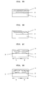
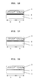
- Figs. 1A-G schematically show cross sections through different embodiments of the security element according to the present invention :
- the concentration of the flake particles in the ink is chosen such that, at maximum, about full (i.e. at least 90%) surface coverage would be obtained in the printed ink if the flake particles were to align, after printing, with their large surfaces parallel to the imprinted substrate surface.
- concentration is in the range of 10 to 30 % by weight of the coating composition.
- the optimum concentration of the flake pigment must be determined experimentally, as a function of the pigment properties (particle size, specific weight, etc.), the thickness of the coating, the orientation angle, and the nature of the substrate, in order to yield the best visual effect.
- the skilled in the art will chose the flake concentration on one hand as low as possible, in order to achieve good visibility to the substrate surface along a predefined viewing direction, and, on the other hand, sufficiently high, such as to give good screening of the substrate surface along some other direction.
- the coating layer is rather thick and the pigment flakes are oriented nearly vertically, then the pigment concentration required to hide the substrate surface when the print is observed near grazing angle turns out to be considerably less than what would be required in the case of horizontally aligned pigment flakes to cover about the full surface.
- the upper limit of the useful pigment concentration is thus the one which would provide, at a given coating thickness and horizontal alignment of the pigment flakes, for substantially complete (i.e. more than 90%) surface coverage, whereas the lower useful pigment concentration is about half of the concentration which would provide for substantially complete surface coverage.
- the mean particle size and the size distribution in a particular pigment lot have an influence on the achievable result.
- a rather large particle size (flake diameter in the range of 10 to 50 ⁇ m), and a size distribution which is as homogeneous as possible, are desirable, in order to yield the optimum effect.
- any flake pigment can be used, provided that it is of appropriate mechanical rigidity to act as lamellae and thus to produce the Venetian Blind effect.
- the flake pigment particles must be opaque, or, at least semi-opaque (semi-transparent), in order to be able to act as screening lamellae.
- Semi-opaque (semi-transparent) in the context of the present disclosure means that the flake is absorbing in at least part of the visible spectrum. According to a preferred embodiment, the flake pigment is totally opaque to visible light.
- Said flake pigment can in particular be chosen from the group consisting of: non-metallic inorganic flakes, metallic inorganic flakes, and organic flakes. Said flake pigment can further carry a thin-film interference coating, or a holographic embossing. Still further, said flake pigment can be a liquid crystal polymer flake, or a magnetic pigment flake, or combine both said properties, i.e. be a magnetic liquid crystal polymer flake. Moreover, said flake pigment can have further additional properties, such as luminescence, electric conduction and/or particular spectral absorption or reflection characteristics.
- optically variable pigments preferably flakes of the thin-film optical interference device disclosed in US-4,434,010; US-5,084,351; US-5,171,363; EP-A-0 227 423 and in related documents, the respective content thereof being incorporated herein by reference, are useful.
- the pigment particle to be used is an optically variable flake having magnetic properties, such as disclosed in US-4,838,648 or in WO 02/073250, the respective content thereof being incorporated herein by reference.
- Curable, transparent binder compositions which can be pigmented with flake particles, to yield inks suitable for realizing the herein disclosed "Venetian Blind” coating on a substrate surface carrying indicia or other features, are disclosed in the art, e.g. in US-4,434,010; US-5,084,351; US-5,171,363; EP-A-0 227 423 and related documents, the respective content thereof being incorporated herein by reference.
- Suitable binder chemistries can be chosen e.g. from the group of vinylic resins, acrylic resins, urethan-alkyde resins, etc., and from mixtures thereof and with other polymers, and the composition can furthermore be either solvent-based or water-based.
- the ink comprising the flake pigment particles is preferably applied on a prepared substrate surface via a liquid-ink printing technique, such as screen-printing or gravure/flexo printing.
- the final thickness of the applied and hardened ink layer is preferably of the order of 10 to 50 ⁇ m, in order to allow for an easy orientation of the pigment flakes in all directions; however, at the price of a higher surface roughness, pigment orientation is feasible at ink layer thickness of as low as 5 ⁇ m. It is noteworthy possible to orient pigment flakes in a binder having a thickness which is much less than the diameter of the pigment flake.
- the flake pigment particles are oriented and subsequently fixed in their oriented positions through the curing of the binder.
- a rapidly curing ink formulation is therefore required, and UV- or EB (electron beam)- curing inks are preferred.
- Ink formulations for physical drying through solvent evaporation or coalescence are less favorable, although they can also find application in particular contexts (see examples).
- Oxy-polymerization drying on the other hand, is too slow to be useful in such context; it could however serve as an additional drying mechanism in a rapid curing (UV, EB, heat-set, coldset, etc.) ink, in order to enhance the binder's long-term resistance.
- a magnetic or magnetizable flake pigment is incorporated into the printing ink.
- the flake pigment particles can be oriented by magnetic means, i.e. by applying magnetic fields to the freshly printed document in order to locally align the magnetic flake pigment along determined directions or planes.
- Methods and means for orienting magnetic pigment particles in a printed ink have been disclosed in the art, for example in US-3,676,273; US-3,791,864; EP-B-0406 667; EP-B-0 556 449; EP-A-0 710 508 and WO 02/90002, as well as in the co-pending application PCT/EP2004/007028, the respective contents thereof being incorporated herein by reference.
- a first surface of the substrate is coated or imprinted with a composition containing said magnetic pigment flakes in a binder. While the coating composition is still wet, i.e. the said binder is not hardened, the substrate, preferably a second surface of it, opposite to the said first surface, is exposed face-to-face to the magnetic field of a magnetic or magnetizable body, such as a permanent magnet, an arrangement of permanent magnets, an engraved permanent magnetic plate, or an arrangement of electromagnets.
- the pigment flakes in the coating composition orient themselves along the lines of the applied magnetic field, and their planes thus adopt a desired local direction in space.
- the coating composition is subsequently hardened, through UV-curing, physical drying by solvent evaporation, etc., thus fixing the oriented pigment particles in their adopted directions.
- a non-magnetic flake pigment can also be mixed with a magnetic non-flake pigment; in the latter case, said magnetic pigment is preferably of very small particle size ( ⁇ 1 ⁇ m), and if possible, of acicular morphology.
- Non-magnetic means of orientation can, however, also be employed in conjunction with the appropriate pigments, such as orientation by electrostatic or electrophoretic means (using an electric field), or also by ultrasonic means (using an acoustic field), such as disclosed in US-A-2003/ 0188842, the respective content thereof being incorporated herein by reference.
- the principle of orientation is the same as described above for magnetic orientation, i.e. the pigment flakes are provided in a coating composition and, before curing of said coating composition, are subjected to the respective external force. Thereafter, the thus achieved orientation is fixed by curing the coating composition.
- any difference in the dielectric constant of the flake pigment particle with respect to the surrounding ink medium will provide for the necessary orienting forces.
- magnetic properties of the flake are not required; the orienting forces are in this case provided by a difference in mechanical properties of the flake pigment particle (rigidity) with respect to the surrounding liquid ink medium.
- the applied, oriented and fixed ink layer is characterized by its angle-dependent transparency variations.
- said transparency variations allow for the production of a large gamut of overt printed security elements which are characterized by their angle-dependent appearance /disappearance of visual features comprised in or on the substrate underneath the oriented "Venetian Blind” ink layer, as well as of features comprised in the said oriented ink layer itself.
- any substrate commonly used for producing security documents or documents of value can be employed.
- suitable substrate materials include, but are not limited to: paper, cardboard, textiles, as well as plastic materials such as polypropylene or Tyvek® substrates.
- the "Venetian Blind” security feature can be directly produced on or in the substrate, or, alternatively and preferred, the latter is made to carry, on at least part of its surface, previously applied indicia, e.g. in the form of a coating, which may be produced according to any method known to the skilled in the art of printing and coating.
- Said substrate is preferably selected from the group consisting of transparent simple substrates, transparent substrates carrying printed or coated indicia, opaque simple substrates, and opaque substrates carrying printed or coated indicia. It is also possible to provide two or more separate coatings on said surface of said substrate.
- Said substrate surface may further comprise a marker substance chosen from the group of: visible luminescent substances, infrared luminescent substances, infrared absorbing substances, and magnetic substances, the effect of which can be modulated by the local orientation of the overlaid flake pigment particles.
- a marker substance chosen from the group of: visible luminescent substances, infrared luminescent substances, infrared absorbing substances, and magnetic substances, the effect of which can be modulated by the local orientation of the overlaid flake pigment particles.
- Said substrate surface may further be or comprise an optical interference device, of the iridescent, diffraction grating (holographic), or thin-film interference layer type.
- optical interference devices are known to the skilled man, for example from US-4,434,010.
- Said substrate surface preferably carries indicia, produced by printing, but any other technique able to produce indicia may be used as well.
- said substrate surface is imprinted using a method chosen from: intaglio printing, letterpress printing, offset printing, screen printing, gravure/flexo printing, laser printing, laser marking, dye sublimation and ink-jet printing.
- Formulations of general printing inks which are suitable for the printing of value documents have been disclosed, e.g. in EP-A-0 088 466; EP-A-0 119 958; EP-A-0 327 788; EP-A-0 340 163; EP-A-0 432 093 and elsewhere. These inks can serve for the imprinting of said substrate surface prior to the production of the security element of the present invention.
- the printed elements on said substrate surface can be light-absorbing, light-reflecting or luminescent in nature, or a combination thereof, and can be produced by the means of spectrally absorbing inks, spectrally reflecting inks, spectrally luminescent inks, etc..
- security elements can be i) material-based, such as, e.g. a material presenting particular spectral absorption or emission, ii) information-based, such as a particular code or number embodied on the document, or iii) tied to a particular process of production, such as, e.g. intaglio printing, as known to the skilled in the art.
- material-based such as, e.g. a material presenting particular spectral absorption or emission
- information-based such as a particular code or number embodied on the document
- iii) tied to a particular process of production such as, e.g. intaglio printing, as known to the skilled in the art.
- the security element according to the present invention in the form of a foil, a thread, a decal or a label, which is subsequently applied to or incorporated in a document of value, according to methods known to the skilled in the art.
- the invention discloses further a method of producing the above-described security element, said method comprising the steps of
- Said substrate surface on said document, said coating layer comprising a flake pigment, and said flake pigment are herein chosen as described above.
- Said coating layer comprising said flake pigment is furthermore preferably applied by a method chosen from screen printing, gravure/flexo printing, or roller coating.
- Said flake pigment comprised in said layer is preferably a magnetic pigment, and said locally orienting of said flake pigment is preferably performed by applying a magnetic field, which, in turn, can be generated either by electromagnetic or by permanent magnetic devices, as described in US-3,676,273; US-3,791,864; EP-B-0406 667; EP-B-0556 449; EP-A-0 710 508 and WO 02/90002, as well as in the co-pending application PCT/EP2004/007028, the respective content thereof being incorporated by reference.
- a magnetic field which, in turn, can be generated either by electromagnetic or by permanent magnetic devices, as described in US-3,676,273; US-3,791,864; EP-B-0406 667; EP-B-0556 449; EP-A-0 710 508 and WO 02/90002, as well as in the co-pending application PCT/EP2004/007028, the respective content thereof being incorporated by reference.
- Said coating layer comprising said flake pigments may furthermore comprise additional security elements such as visible luminescent compounds, infrared luminescent compounds, infrared absorbing compounds, and magnetic substances.
- Suitable inks for the printing of the "Venetian Blind” coating layer comprising magnetically or otherwise orientable flake pigment particles are preferably chosen from the group of liquid inks, such as screen-printing and gravure printing / flexographic inks. Exemplary ink formulas are given in the following. Unless otherwise indicated, percentages are by weight.
- Example 1 An OVI ® flexography ink comprising a magnetic optically variable pigment:
- Neocryl BT-105 (Avecia) 45 % Deionised water 19 % Dowanol DPM (Dow) 6.5 % AMP-95 TM (Angus Chemie GmbH) 1.5 % Neocryl BT-100 7 % Tego Foamex 800 (Tego Chemie Service GmbH) 0.5 % Aerosil 200 (Degussa) 0.5 % Magnetic Optically Variable Pigment (FLEX Prod. Inc.)* 20 % * green-to-blue, 5 layers design, Cr/MgF 2 /Ni/MgF 2 /Cr as disclosed in patent US-4,838,648.
- the ingredients were dispersed together and the viscosity of the resulting mixture was adjusted with deionised water, so as to reach the value of 20-40 s DIN4 at 25°C.
- the ink was applied through flexographic printing onto a substrate (banknote paper), carrying a laser-printed black pattern (consisting of indicia "10") on its surface, and the so imprinted substrate was exposed, while still wet, to a uniform magnetic field, hereby orienting the magnetic pigment particles along the field lines in a 45° oblique direction with respect to the substrate surface.
- the ink was then dried in situ using a flow of hot air.
- the security element according to the present embodiment provided excellent copy protection for sensible information, due to the inability of scanning devices to read at grazing angle.
- Example 2 An OVI ® silkscreen ink, comprising a magnetic optically variable pigment :
- the vinyl resin was dissolved in the ketone-glycol solvent prior to the incorporation of the additive and the pigment.
- the viscosity was adjusted using the same solvent blend so as to reach the value of 600 to 1'500 mPa ⁇ s at 25°C.
- the ink was applied in the form of a screen-printed patch onto a substrate carrying a printed pattern (ink-jet printed colored dots), and the so imprinted substrate was subjected, while still wet, to a structured magnetic field, hereby locally orienting the magnetic pigment particles in two opposed 45° oblique directions with respect to the substrate surface.
- the ink was then dried in situ using a flow of hot air.
- the substrate surface element printed to the right was revealed by tilting the print to the left so as to observe it from the right (Fig 3A).
- the substrate surface element printed on the left was revealed by tilting the print to the right so as to observe it from the left (Fig. 3C).
- the elements of the substrate surface were hidden altogether (Fig. 3B).
- the substrate surface element printed on the left was revealed by tilting the print to the left so as to observe it from the right (Fig 4A).
- the substrate surface element printed on the right was revealed by tilting the print to the right so as to observe it from the left (Fig. 4C).
- the elements of the substrate surface were hidden altogether (Fig. 4B).
- Example 3 A UV drying screen ink:
- the ink was applied in the form of a screen-printed patch onto a substrate carrying indicia. After orientation of the magnetic pigment particles, the ink was dried in situ using a UV-radiation curing unit.
- Example 4 A coercive magnetic gravure ink:
- the resins were dissolved in the solvents prior to the incorporation of the pigments.
- the viscosity was adjusted with solvent blend to reach the value of 20-40 s DIN4 at 25°C.
- the ink was applied to a substrate carrying indicia, by the means of a gravure printing process. After orientation of the pigment particles with the help of a magnetic field, the ink was dried in situ using a flow of hot air.
- the given examples illustrate how, by the means of the Venetian Blind Effect, the direction of visibility of a substrate surface, carrying indicia or other features, can be freely defined, by giving a corresponding orientation to flake pigment particles contained in a transparent coating which is applied over said substrate surface. Based on the given description and the examples, the skilled man will be able to derive further embodiments of the disclosed invention.
Abstract
The invention discloses a security element having a coating layer which appears transparent at certain angles of view, giving visual access to underlying information (2), whilst staying opaque at other angles of view. Documents of value, right, identity, security labels or branded goods comprising said security element, as well as a method for producing said security element, are also disclosed. Using appropriate substrate (1) surfaces, optically variable and otherwise angle-dependent visual effects can be realized.
Description
- The present invention is in the field of security documents, more particularly in the field of security elements aimed to protect security documents against copying (illegal reproduction) and counterfeiting. It discloses a security element having a coating layer which appears transparent at certain angles of view, giving visual access to underlying information, whilst staying opaque at other angles of view. Security documents comprising said security element, as well as a method for producing said security element, are also disclosed. Combined with appropriate substrate surfaces, optically variable and other angle-dependent visual effects can be realized.
- Coatings, printings and markings exhibiting a viewing-angle-dependant visual appearance ("optically variable devices", OVDs) are used as efficient anti-copy means on bank notes and security documents (cf. "Optical Document Security", ed. R. L. van Renesse; 2nd edition, 1998, Artech House, London). Among the OVDs, optically variable ink (OVI® , EP-A-0 227 424) holds a pre-eminent position as an "overt" security element, since its first use on a banknote back in 1987. Optically variable inks are formulated on the base of optically variable pigments (OVPs), preferably flakes of the thin-film optical interference device disclosed in US-4,434,010; US-5,084,351; US-5,171,363; EP-A-0 227 423 and in related documents.
- Printed optically variable elements on security documents are primarily used for the "overt" authentication of security documents by the unaided human eye, through the user's checking of said element's spectral reflection properties, i.e. its color at two or more different angles of view, at least at near-orthogonal and at near grazing view with respect to the plane of the document. Said angle-dependent color is a "simple message of authenticity", which cannot be reproduced without having access to the source of the genuine optically variable security element, and which can easily be checked by the "man on the street".
- The increasing commercial availability of non-security color-shifting pigments, mainly for decorative applications, calls for the development of upgraded "overt" security elements, for use on "next generation" banknotes and on other protected documents. Such upgraded security element must comply, among others, with the following requirements: i) it should carry a "simple message of authenticity" which can be rapidly and easily identified by the "man on the street"; ii) it should not be reproducible without having access to the genuine particular security material and/or to the required particular production or security printing technology; iii) it should not be under commercial pressure from the decorative market or from another large industrial application field.
- In US-3,676,273; US-3,791,864; EP-B-0 406 667; EP-B-0 556 449 B1; EP-A-0 710 508 and WO 02/90002, as well as in the co-pending application PCT/EP2004/007028, methods and devices are disclosed, which can be used to impart a particular orientation to magnetic optically variable pigment flakes in a freshly printed optically variable coating composition, prior to the drying (hardening) of the said composition. In such a way, magnetically induced patterns which are highly resistant to counterfeit can be produced. The security element in question can only be produced by having access to both, the source of the optically variable magnetic pigment or the corresponding ink, and the particular technology employed to print said ink and to orient said pigment in the printed ink. On the other hand, the visual pattern resulting from said magnetic orientation of optically variable pigment in a printed ink is easily recognized and identified by the 'man on the street'.
- The present invention discloses a different solution to the stated technical problem of providing upgraded "overt" copy-protection security elements for the next generation of banknotes and other protected documents. The security element for documents of value, of rights, of identity, security labels, or branded goods, according to the present invention, comprises a substrate which may contain indicia or other visible features in or on its surface, and, on at least part of the said substrate surface, a coating layer comprising pigment flakes in a cured, transparent binder, wherein the said pigment flakes in said coating layer are absorbing in at least part of the visible spectrum, and are locally oriented such that the coating layer shows local, angle-dependent variations of its transparency, i.e. that it gives visibility to the underlying substrate surface along at least one specific direction of observation and impedes visibility to the underlying substrate surface along at least another direction of observation.
- In the context of the present invention, "transparent" is used in the sense of "allowing the human eye to see through, at least in some part of the visible spectrum", and the term "angle-dependent variations of its transparency" is to be understood in the sense that the coating layer, when viewed under a first angle, allows the perception of the underlying substrate surface and of indicia or other features it may contain. When viewed under some other angle, different from the said first angle, said coating layer hides the said underlying substrate surface and the indicia or other features it may contain.
- The described visual phenomena are achieved, according to the present invention, through a "Venetian Blind effect", which is produced by correspondingly oriented pigment flakes comprised in the said coating layer.
- Said pigment flakes are noteworthy locally oriented such that, along a specific direction of observation, they give visibility to the underlying substrate surface, such that indicia or other features present on or in the said substrate surface become apparent to the observer. Said direction of observation is hereby defined by the planes of the oriented pigment flakes, i.e. the pigment flakes are locally oriented such that their planes contain at least one common vector, which corresponds to the said direction of observation. Said planes of said flakes may further be oriented all in parallel, or, alternatively, a second vector of said planes may have a random orientation whilst a first vector of said planes corresponds to the said common direction of observation.
- When looking along a direction which is substantially different from said direction common to all planes of the locally oriented pigment flakes, the visibility to the underlying substrate surface is screened by the pigment flakes, which act towards the observer in the manner of a Venetian Blind. This screening mechanism can be used to produce a large variety of optically variable effects, such as angle-dependent color, luminescence, etc., depending on the underlying substrate surface, the precise orientation of the pigment flakes, as well as the physical properties of the pigment itself and of the coating composition containing it.
- In particular, the pigment flakes need not to be oriented vertically to produce the said Venetian blind effect; in fact, any orientation of the pigment flakes which is substantially different from an alignment with the plane of the substrate surface will exhibit the Venetian Blind effect. A viewing direction chosen close to grazing angle, however, has the disadvantage of a large perspective-distortion; i.e. the indicia or features on or in the substrate surface are only perceived with difficulty. For this reason, the oriented pigment flake planes are chosen to preferably have an elevation angle (= viewing direction) of at least 30° with respect to the plane of the substrate surface.
- To produce said Venetian Blind effect, the pigment particles must have a "flake shape", i.e. their thickness must be small compared to their length and width, such as e.g. is the case for the pigment particles disclosed in EP-A-0 227 423, the respective content thereof being incorporated herein by reference. Said particles have typical dimensions of 1 µm thickness by 10 to 30 µm length and width. Particles displaying such type of geometry are suited to embody the Venetian Blind effect of the present invention, if their orientation in the printed ink is appropriately controlled.
- The security element of the present invention, displaying a Venetian Blind effect is preferably produced by first providing a substrate with a desired surface of determined size, which may contain indicia or other appropriate perceptible features on or in said surface. Said substrate surface is then coated at least in part with a composition containing flake pigment particles and a curable, transparent binder. After coating, said flake pigment particles are locally oriented by an appropriate method, and finally, the composition is cured, in order to fix the oriented pigment flakes in their positions.
- A large variety of optical effects can be produced by appropriate combinations of substrate surfaces and areas exhibiting locally oriented "Venetian blind" effects, as illustrated in Figs. 1A-G, which schematically show cross sections through different embodiments of the security element according to the present invention :
- In Fig. 1A, a substrate (1) carries printed indicia (2) on part of its surface, which are overprinted with an ink containing a flake pigment (3). All the pigment particles (3) in the printed ink are oriented and fixed, such as to adopt a same oblique position, pointing about 45° to the right. The printed indicia (2) can be seen when viewed at a 45° angle from the right (i.e. when looking in parallel to the alignment axes of the pigments (3)); but not at all when viewed from the left.
- In Fig. 1B, a similar arrangement as in Fig. 1A is shown except that the flake pigment particles (3) are now oriented and fixed pointing about 45° to the left. Accordingly, the indicia can be seen when viewed from the left; but not when viewed from the right.
- In Fig. 1C, a similar arrangement as in Fig. 1A is shown, except that the flake pigment particles (3) are locally oriented and fixed selectively along two different directions; noteworthy about 45° to the left in zone A, and about 45° to the right in zone B. Indicia in zone A can be seen when viewed from the left, indicia in zone B cannot. Indicia in zone B can be seen when viewed from the right, indicia in zone A cannot.
- In Fig. 1D, a similar arrangement as in Fig. 1C is shown except having the orientation of the flake pigment particles (3) in zone A and zone B reversed. Indicia in zone A can be seen from the right, indicia in zone B cannot. Indicia in zone B can be seen from the left, indicia in zone A cannot.
- In Fig. 1E, a homogeneously colored surface (2) on a substrate (1) is overprinted with an ink containing flake pigment (3) of the said type. The pigment particles (3) are oriented and fixed according to two different directions in areas A and B, respectively. The colored substrate surface (2) appears differently in areas A and B, depending on the viewing angle, and exhibits a "flip-flop" effect upon tilting the substrate forth and back between areas A and B.
- In Fig. 1F, the contrast between areas A and B is further enhanced, compared to Fig. 1E, through an imprinting of the substrate surface (2) itself with an iridescent or optically variable ink. In particular, using differently oriented and fixed flake pigment particles (3) in areas A and B, respectively, printed on top of said iridescent substrate surface (2), area A can be made to appear lighter when observed from the left, and darker when observed from the right, than it would be the case of a substrate surface (2) imprinted with purely absorbing inks.
- In Fig. 1G, a fluorescent material (2) comprised in or on a substrate (1) is provided with angle-dependent properties by overprinting it with an ink containing oriented and fixed flake pigment particles (3). To observe the fluorescence in this embodiment, both, the excitation (e.g. by a UV source) and the observation (e.g. by eye) must take place at the same oblique angle, i.e. 45° from the right for zone A, and 45° from the left for zone B, respectively. Using excitation from the left and observation from the right, or vice-versa, will not show any luminescence.
- The concentration of the flake particles in the ink is chosen such that, at maximum, about full (i.e. at least 90%) surface coverage would be obtained in the printed ink if the flake particles were to align, after printing, with their large surfaces parallel to the imprinted substrate surface. In the case of the preferred flake pigments of EP-A-0 227 423, such concentration is in the range of 10 to 30 % by weight of the coating composition. In any particular case, the optimum concentration of the flake pigment must be determined experimentally, as a function of the pigment properties (particle size, specific weight, etc.), the thickness of the coating, the orientation angle, and the nature of the substrate, in order to yield the best visual effect.
- In general, the skilled in the art will chose the flake concentration on one hand as low as possible, in order to achieve good visibility to the substrate surface along a predefined viewing direction, and, on the other hand, sufficiently high, such as to give good screening of the substrate surface along some other direction. In particular, if the coating layer is rather thick and the pigment flakes are oriented nearly vertically, then the pigment concentration required to hide the substrate surface when the print is observed near grazing angle turns out to be considerably less than what would be required in the case of horizontally aligned pigment flakes to cover about the full surface.
- The upper limit of the useful pigment concentration is thus the one which would provide, at a given coating thickness and horizontal alignment of the pigment flakes, for substantially complete (i.e. more than 90%) surface coverage, whereas the lower useful pigment concentration is about half of the concentration which would provide for substantially complete surface coverage.
- As already stated, the mean particle size and the size distribution in a particular pigment lot have an influence on the achievable result. A rather large particle size (flake diameter in the range of 10 to 50 µm), and a size distribution which is as homogeneous as possible, are desirable, in order to yield the optimum effect. The presence of a substantial fraction of small particles in a pigment lot, on the other hand, adversely influences the "Venetian Blind" effect.
- According to the present invention, as stated above, any flake pigment can be used, provided that it is of appropriate mechanical rigidity to act as lamellae and thus to produce the Venetian Blind effect. Moreover, as evident to the skilled man, the flake pigment particles must be opaque, or, at least semi-opaque (semi-transparent), in order to be able to act as screening lamellae. Semi-opaque (semi-transparent) in the context of the present disclosure means that the flake is absorbing in at least part of the visible spectrum. According to a preferred embodiment, the flake pigment is totally opaque to visible light.
- Said flake pigment can in particular be chosen from the group consisting of: non-metallic inorganic flakes, metallic inorganic flakes, and organic flakes. Said flake pigment can further carry a thin-film interference coating, or a holographic embossing. Still further, said flake pigment can be a liquid crystal polymer flake, or a magnetic pigment flake, or combine both said properties, i.e. be a magnetic liquid crystal polymer flake. Moreover, said flake pigment can have further additional properties, such as luminescence, electric conduction and/or particular spectral absorption or reflection characteristics.
- According to the present invention, optically variable pigments (OVPs), preferably flakes of the thin-film optical interference device disclosed in US-4,434,010; US-5,084,351; US-5,171,363; EP-A-0 227 423 and in related documents, the respective content thereof being incorporated herein by reference, are useful. It is particularly preferred that the pigment particle to be used is an optically variable flake having magnetic properties, such as disclosed in US-4,838,648 or in WO 02/073250, the respective content thereof being incorporated herein by reference.
- Curable, transparent binder compositions which can be pigmented with flake particles, to yield inks suitable for realizing the herein disclosed "Venetian Blind" coating on a substrate surface carrying indicia or other features, are disclosed in the art, e.g. in US-4,434,010; US-5,084,351; US-5,171,363; EP-A-0 227 423 and related documents, the respective content thereof being incorporated herein by reference. Suitable binder chemistries can be chosen e.g. from the group of vinylic resins, acrylic resins, urethan-alkyde resins, etc., and from mixtures thereof and with other polymers, and the composition can furthermore be either solvent-based or water-based.
- The ink comprising the flake pigment particles is preferably applied on a prepared substrate surface via a liquid-ink printing technique, such as screen-printing or gravure/flexo printing. The final thickness of the applied and hardened ink layer is preferably of the order of 10 to 50 µm, in order to allow for an easy orientation of the pigment flakes in all directions; however, at the price of a higher surface roughness, pigment orientation is feasible at ink layer thickness of as low as 5 µm. It is noteworthy possible to orient pigment flakes in a binder having a thickness which is much less than the diameter of the pigment flake.
- In the applied coating layer, the flake pigment particles are oriented and subsequently fixed in their oriented positions through the curing of the binder. A rapidly curing ink formulation is therefore required, and UV- or EB (electron beam)- curing inks are preferred. Ink formulations for physical drying through solvent evaporation or coalescence are less favorable, although they can also find application in particular contexts (see examples). Oxy-polymerization drying, on the other hand, is too slow to be useful in such context; it could however serve as an additional drying mechanism in a rapid curing (UV, EB, heat-set, coldset, etc.) ink, in order to enhance the binder's long-term resistance.
- According to a preferred embodiment, a magnetic or magnetizable flake pigment is incorporated into the printing ink. The flake pigment particles can be oriented by magnetic means, i.e. by applying magnetic fields to the freshly printed document in order to locally align the magnetic flake pigment along determined directions or planes. Methods and means for orienting magnetic pigment particles in a printed ink have been disclosed in the art, for example in US-3,676,273; US-3,791,864; EP-B-0406 667; EP-B-0 556 449; EP-A-0 710 508 and WO 02/90002, as well as in the co-pending application PCT/EP2004/007028, the respective contents thereof being incorporated herein by reference.
- To achieve magnetic orientation of the pigment flakes, a first surface of the substrate is coated or imprinted with a composition containing said magnetic pigment flakes in a binder. While the coating composition is still wet, i.e. the said binder is not hardened, the substrate, preferably a second surface of it, opposite to the said first surface, is exposed face-to-face to the magnetic field of a magnetic or magnetizable body, such as a permanent magnet, an arrangement of permanent magnets, an engraved permanent magnetic plate, or an arrangement of electromagnets. The pigment flakes in the coating composition orient themselves along the lines of the applied magnetic field, and their planes thus adopt a desired local direction in space. The coating composition is subsequently hardened, through UV-curing, physical drying by solvent evaporation, etc., thus fixing the oriented pigment particles in their adopted directions.
- A non-magnetic flake pigment can also be mixed with a magnetic non-flake pigment; in the latter case, said magnetic pigment is preferably of very small particle size (< 1 µm), and if possible, of acicular morphology.
- Non-magnetic means of orientation can, however, also be employed in conjunction with the appropriate pigments, such as orientation by electrostatic or electrophoretic means (using an electric field), or also by ultrasonic means (using an acoustic field), such as disclosed in US-A-2003/ 0188842, the respective content thereof being incorporated herein by reference. The principle of orientation is the same as described above for magnetic orientation, i.e. the pigment flakes are provided in a coating composition and, before curing of said coating composition, are subjected to the respective external force. Thereafter, the thus achieved orientation is fixed by curing the coating composition.
- In particular, if electrostatic or electrophoretic orientation is used, magnetic properties of the flake are not required; any difference in the dielectric constant of the flake pigment particle with respect to the surrounding ink medium will provide for the necessary orienting forces. Also in the orientation by an ultrasonic field, magnetic properties of the flake are not required; the orienting forces are in this case provided by a difference in mechanical properties of the flake pigment particle (rigidity) with respect to the surrounding liquid ink medium.
- The applied, oriented and fixed ink layer is characterized by its angle-dependent transparency variations. Using appropriate substrate surfaces, said transparency variations allow for the production of a large gamut of overt printed security elements which are characterized by their angle-dependent appearance /disappearance of visual features comprised in or on the substrate underneath the oriented "Venetian Blind" ink layer, as well as of features comprised in the said oriented ink layer itself.
- According to the present invention, any substrate commonly used for producing security documents or documents of value can be employed. Suitable substrate materials include, but are not limited to: paper, cardboard, textiles, as well as plastic materials such as polypropylene or Tyvek® substrates. The "Venetian Blind" security feature can be directly produced on or in the substrate, or, alternatively and preferred, the latter is made to carry, on at least part of its surface, previously applied indicia, e.g. in the form of a coating, which may be produced according to any method known to the skilled in the art of printing and coating.
- Said substrate is preferably selected from the group consisting of transparent simple substrates, transparent substrates carrying printed or coated indicia, opaque simple substrates, and opaque substrates carrying printed or coated indicia. It is also possible to provide two or more separate coatings on said surface of said substrate.
- Said substrate surface may further comprise a marker substance chosen from the group of: visible luminescent substances, infrared luminescent substances, infrared absorbing substances, and magnetic substances, the effect of which can be modulated by the local orientation of the overlaid flake pigment particles.
- Said substrate surface may further be or comprise an optical interference device, of the iridescent, diffraction grating (holographic), or thin-film interference layer type. Such interference devices are known to the skilled man, for example from US-4,434,010.
- Said substrate surface preferably carries indicia, produced by printing, but any other technique able to produce indicia may be used as well. Preferably, said substrate surface is imprinted using a method chosen from: intaglio printing, letterpress printing, offset printing, screen printing, gravure/flexo printing, laser printing, laser marking, dye sublimation and ink-jet printing.
- Formulations of general printing inks which are suitable for the printing of value documents have been disclosed, e.g. in EP-A-0 088 466; EP-A-0 119 958; EP-A-0 327 788; EP-A-0 340 163; EP-A-0 432 093 and elsewhere. These inks can serve for the imprinting of said substrate surface prior to the production of the security element of the present invention.
- The printed elements on said substrate surface can be light-absorbing, light-reflecting or luminescent in nature, or a combination thereof, and can be produced by the means of spectrally absorbing inks, spectrally reflecting inks, spectrally luminescent inks, etc..
- All elements described above can be combined with additional security elements, which can be i) material-based, such as, e.g. a material presenting particular spectral absorption or emission, ii) information-based, such as a particular code or number embodied on the document, or iii) tied to a particular process of production, such as, e.g. intaglio printing, as known to the skilled in the art.
- In a further embodiment, it is also possible to separately prepare the security element according to the present invention, in the form of a foil, a thread, a decal or a label, which is subsequently applied to or incorporated in a document of value, according to methods known to the skilled in the art.
- The invention discloses further a method of producing the above-described security element, said method comprising the steps of
- a) providing a substrate having a surface, which surface may contain indicia or other visible features;
- b) applying, on top of at least part of said substrate surface, a coating layer comprising orientable flake pigment particles and a curable, transparent binder;
- c) locally orienting said flake pigment particles in said coating layer, such as to give visibility to the underlying substrate surface along at least one specific direction of observation and to impede visibility to the underlying substrate surface along at least another direction of observation;
- d) curing said coating layer, so as to fix the orientation of the said flake pigment particles;
- Said substrate surface on said document, said coating layer comprising a flake pigment, and said flake pigment are herein chosen as described above. Said coating layer comprising said flake pigment is furthermore preferably applied by a method chosen from screen printing, gravure/flexo printing, or roller coating.
- Said flake pigment comprised in said layer is preferably a magnetic pigment, and said locally orienting of said flake pigment is preferably performed by applying a magnetic field, which, in turn, can be generated either by electromagnetic or by permanent magnetic devices, as described in US-3,676,273; US-3,791,864; EP-B-0406 667; EP-B-0556 449; EP-A-0 710 508 and WO 02/90002, as well as in the co-pending application PCT/EP2004/007028, the respective content thereof being incorporated by reference.
- Said coating layer comprising said flake pigments may furthermore comprise additional security elements such as visible luminescent compounds, infrared luminescent compounds, infrared absorbing compounds, and magnetic substances.
- The invention is hereafter further explained with reference to exemplary and non-limiting figures and embodiments.
- Fig. 1A-G
- schematically show cross sections through different embodiments of the security element according to the present invention.
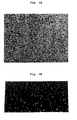
- Fig. 2
- shows an embodiment of the invention having a single oblique orientation of the "Venetian Blind" overprint, similar to the schemes shown in Fig. 1A and 1B. The underlying indicia are visible at grazing view (Fig. 2B), but not at orthogonal view (Fig. 2A).
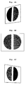
- Fig. 3
- shows an embodiment of the invention having two different orientations of the "Venetian Blind" overprint, similar to the scheme shown in Fig. 1C. A first (right) part of the underlying indicia is visible when tilting the sample to the left (Fig. 3A); a second (left) part of the underlying indicia is visible when tilting the sample to the right (Fig. 3C); none of the underlying indicia are visible at orthogonal view (Fig. 3B).
- Fig. 4
- shows an embodiment of the invention which is similar to the embodiment of Fig. 3, but inverted left-to-right, according to the scheme shown in Fig. 1D: now, a first (left) part of the underlying indicia is visible when tilting the sample to the left (Fig. 4A); a second (right) part of the underlying indicia is visible when tilting the sample to the right (Fig. 4C); none of the underlying indicia are visible at orthogonal view (Fig. 4B).
- Fig. 5
- shows an embodiment of the invention which is similar to the embodiment of Fig. 3 and 4, but now with two different orientations of the "Venetian Blind" over-print in up-down direction.
- Fig. 6
- shows the visual authentication of an embodiment of the security element of the present invention by a simple tilting of the document carrying it.
- General printing ink formulations for the printing of value documents, which can serve for the imprinting of said substrate surface underneath the "Venetian Blind" coating, have been disclosed in the prior art, e.g. in EP-B-0 088 466; EP-B-0 119 958; EP-B-0327 788; EP-B-0340 163; EP-B-0432 093, the respective content thereof being incorporated by reference.
- Suitable inks for the printing of the "Venetian Blind" coating layer comprising magnetically or otherwise orientable flake pigment particles are preferably chosen from the group of liquid inks, such as screen-printing and gravure printing / flexographic inks. Exemplary ink formulas are given in the following. Unless otherwise indicated, percentages are by weight.
-
Neocryl BT-105 (Avecia) 45 % Deionised water 19 % Dowanol DPM (Dow) 6.5 % AMP-95™ (Angus Chemie GmbH) 1.5 % Neocryl BT-100 7 % Tego Foamex 800 (Tego Chemie Service GmbH) 0.5 % Aerosil 200 (Degussa) 0.5 % Magnetic Optically Variable Pigment (FLEX Prod. Inc.)* 20 % * green-to-blue, 5 layers design, Cr/MgF2 /Ni/MgF2/Cr as disclosed in patent US-4,838,648. - The ingredients were dispersed together and the viscosity of the resulting mixture was adjusted with deionised water, so as to reach the value of 20-40 s DIN4 at 25°C.
- The ink was applied through flexographic printing onto a substrate (banknote paper), carrying a laser-printed black pattern (consisting of indicia "10") on its surface, and the so imprinted substrate was exposed, while still wet, to a uniform magnetic field, hereby orienting the magnetic pigment particles along the field lines in a 45° oblique direction with respect to the substrate surface. The ink was then dried in situ using a flow of hot air.
- As shown in Fig. 2 and Fig. 6, under illumination conditions where a light source was located above the observer, the printed area appeared uniformly green when the print was observed orthogonally to the substrate plane; (Fig. 2A, 6A). When the print was tilted backwards (grazing view; Fig. 2B, 6B), the underlying black indicia, "10", became visible. The security element according to the present embodiment provided excellent copy protection for sensible information, due to the inability of scanning devices to read at grazing angle.
-
Diethyl ketone 23 % Ethyl diglycol 29 % Solution Vinyl VMCA (Union Carbide) 27 % BYK-053 (BYK) additive 1 % Magnetic Optically Variable Pigment (FLEX Prod. Inc.)* 20 % * magenta-to-green, 7 layers design as disclosed in WO 02/73250: Cr/MgF2 /Al/Ni/Al/MgF2/Cr. - The vinyl resin was dissolved in the ketone-glycol solvent prior to the incorporation of the additive and the pigment. The viscosity was adjusted using the same solvent blend so as to reach the value of 600 to 1'500 mPa·s at 25°C.
- The ink was applied in the form of a screen-printed patch onto a substrate carrying a printed pattern (ink-jet printed colored dots), and the so imprinted substrate was subjected, while still wet, to a structured magnetic field, hereby locally orienting the magnetic pigment particles in two opposed 45° oblique directions with respect to the substrate surface. The ink was then dried in situ using a flow of hot air.
- In the exemplary embodiment shown in Fig. 3, corresponding to Scheme 1C above, the substrate surface element printed to the right was revealed by tilting the print to the left so as to observe it from the right (Fig 3A). Conversely, the substrate surface element printed on the left was revealed by tilting the print to the right so as to observe it from the left (Fig. 3C). When the print was observed orthogonally to the substrate plane, the elements of the substrate surface were hidden altogether (Fig. 3B).
- In the exemplary embodiment shown in Fig. 4, corresponding to Scheme 1D above, the substrate surface element printed on the left was revealed by tilting the print to the left so as to observe it from the right (Fig 4A). Conversely, the substrate surface element printed on the right was revealed by tilting the print to the right so as to observe it from the left (Fig. 4C). When the print was observed orthogonally to the substrate plane, the elements of the substrate surface were hidden altogether (Fig. 4B).
- In the exemplary embodiment shown in Fig. 5, two opposed 45° oblique directions of the "Venetian Blind" were vertically arranged on top of a substrate carrying the vertically arranged letters "A" and "B" on its surface. The indicia printed on the upper part, i.e. the letter "A", were revealed by tilting the print backwards, as depicted in Fig 5A. Conversely, the indicia printed on the lower part, i.e. the letter "B", were revealed by tilting the print forward, as depicted in Fig. 5C. When the print was observed orthogonally to the substrate plane, neither "A" nor "B", printed on the substrate surface, were visible, as shown in Fig. 5B.
- The indicated embodiments were also realized on the base of other flake pigments and using different ink chemistries, as disclosed in the following:
-
Epoxyacrylate oligomer 40 % Trimethylolpropane triacrylate monomer 15 % Tripropyleneglycol diacrylate monomer 15% Genorad 16 (Rahn) 1 % Colored magnetic pigment (SiO2-coated iron particles) (BASF) 20 % Aerosil 200 (Degussa-Huels) 1 % Irgacure 500 (CIBA) 6% Genocure EPD (Rahn) 2% - The ink was applied in the form of a screen-printed patch onto a substrate carrying indicia. After orientation of the magnetic pigment particles, the ink was dried in situ using a UV-radiation curing unit.
-
Ethanol 25 % Ethyl acetate 25 % Dicyclohexylphtalate (Unimoll 66, Bayer) 5 % Fumaric acid modified rosin (ERKAMAR 3270, Robert Kraemer GmbH & Co) 5 % Polyvinylbutyral resin (Pioloform BN18, Wacker-Chemie GmbH) 13 % Magnetic pigment 345 (BASF) 5 % HELICONE® HC MAPLE S (Wacker Chemie GmbH) 10 % Ethanol 4 % Ethyl acetate 8 % - The resins were dissolved in the solvents prior to the incorporation of the pigments. The viscosity was adjusted with solvent blend to reach the value of 20-40 s DIN4 at 25°C. The ink was applied to a substrate carrying indicia, by the means of a gravure printing process. After orientation of the pigment particles with the help of a magnetic field, the ink was dried in situ using a flow of hot air.
- The given examples illustrate how, by the means of the Venetian Blind Effect, the direction of visibility of a substrate surface, carrying indicia or other features, can be freely defined, by giving a corresponding orientation to flake pigment particles contained in a transparent coating which is applied over said substrate surface. Based on the given description and the examples, the skilled man will be able to derive further embodiments of the disclosed invention.
Claims (18)
- Security element for a document of value, right, identity, for a security label or a branded good, comprising a substrate, which may contain indicia or other visible features in or on its surface, and on at least part of the said substrate surface, a coating layer comprising pigment flakes in a cured, transparent binder, wherein said pigment flakes in said coating layer are absorbing in at least part of the visible spectrum, and are locally oriented such as to give visibility to the underlying substrate surface along at least one specific direction of observation and to impede visibility to the underlying substrate surface along at least another direction of observation.
- Security element according to claim 1, wherein said substrate is selected from the group consisting of transparent simple substrates, transparent substrates carrying printed or coated indicia, opaque simple substrates, and opaque substrates carrying printed or coated indicia.
- Security element according to one of claims 1 to 2, wherein said coating layer and/or said substrate comprises a marker substance selected from the group of visible luminescent substances, infrared luminescent substances, infrared absorbing substances, and magnetic substances.
- Security element according to one of claims 1 to 3, wherein said substrate carries an optical interference device.
- Security element according to one of claims 1 to 4, wherein said pigment flake is selected from the group consisting of non-metallic inorganic flakes, metallic inorganic flakes, and organic flakes.
- Security element according to claim 5, wherein said pigment flake is selected from the group consisting of thin-film interference pigments and liquid crystal polymer pigments.
- Security element according to one of claims 1 to 6, wherein said pigment flake carries a holographic embossing.
- Security element according to one of claims 1 to 7, wherein said pigment flake is a magnetic particle.
- Security element according to one of claims 1 to 8, wherein the concentration of said flake pigment in said coating layer is chosen in the range between 50% to 100% of the concentration which would provide for a substantially complete surface coverage in the absence of orientation.
- Security element according to one of claims 1 to 9, wherein the oriented pigment flakes in said coating layer have an elevation angle of the pigment flake planes of at least 30° with respect to the plane of the substrate surface.
- Security element according to one of claims 1 to 10, wherein the flake pigment has a flake average diameter in the range of between 10 and 50 micrometers.
- Security element according to one of claims 1 to 11, wherein said flake pigment is opaque in the visible spectrum.
- Method of producing a security element according to any one of claims 1 to 12, comprising the steps ofa) providing a substrate having a surface, which surface may contain indicia or other visible features;b) applying, on top of at least part of the said substrate surface, a coating layer comprising orientable flake pigment particles and a curable, transparent binder;c) locally orienting said flake pigment particles in said coating layer, such as to give visibility to the underlying substrate surface along at least one specific direction of observation, and to impede visibility to the underlying substrate surface along at least another direction of observation;d) curing said coating layer, so as to fix the orientation of the said flake pigment particles;
wherein the said flake pigment particles are absorbing in at least part of the visible spectrum. - Method according to claim 13, wherein said coating layer comprising said flake pigment is applied by a method selected from the group consisting of screen printing, gravure/flexo printing, and roller coating.
- Method according to claim 13 or 14, wherein said indicia are applied onto said substrate surface by a method selected from the group consisting of intaglio printing, letterpress printing, offset printing, screen printing, gravure/flexo printing, laser printing, laser marking, dye sublimation, and ink-jet printing.
- Method according to one of claims 13 to 15, wherein said local orientation of said flake pigment is achieved by applying a field chosen from the group consisting of magnetic fields, electric fields, acoustic fields.
- Document of value, right, identity, security label, branded good, comprising a security element according to one of claims 1 to 12.
- Use of a security element according to one of claims 1 to 12, for the prevention of counterfeit or reproduction, on a document of value, right, identity, a security label or a branded good.
Priority Applications (35)
| Application Number | Priority Date | Filing Date | Title |
|---|---|---|---|
| EP04029170A EP1669213A1 (en) | 2004-12-09 | 2004-12-09 | Security element having a viewing-angle dependent aspect |
| PCT/EP2005/055884 WO2006061301A1 (en) | 2004-12-09 | 2005-11-10 | Security element having a viewing-angle dependent aspect |
| JP2007544865A JP5118490B2 (en) | 2004-12-09 | 2005-11-10 | Security element with a viewing angle dependent appearance |
| KR1020077015269A KR101170585B1 (en) | 2004-12-09 | 2005-11-10 | Security element having a viewing-angle dependent aspect, method of producing the security element and items comprising the security element |
| AU2005313398A AU2005313398C1 (en) | 2004-12-09 | 2005-11-10 | Security element having a viewing-angle dependent aspect |
| AP2007004005A AP2434A (en) | 2004-12-09 | 2005-11-10 | Security element having a viewing-angle dependent aspect |
| DE602005020058T DE602005020058D1 (en) | 2004-12-09 | 2005-11-10 | SECURITY ELEMENT WITH AN APPEARANCE DEPENDENT ON THE VIEW OF ANGLES |
| PT05807996T PT1819525E (en) | 2004-12-09 | 2005-11-10 | Security element having a viewing-angle dependent aspect |
| PL05807996T PL1819525T3 (en) | 2004-12-09 | 2005-11-10 | Security element having a viewing-angle dependent aspect |
| ES05807996T ES2341354T3 (en) | 2004-12-09 | 2005-11-10 | SECURITY ELEMENT WITH A DEPENDENT ASPECT OF THE VISION ANGLE. |
| BRPI0518595A BRPI0518595B1 (en) | 2004-12-09 | 2005-11-10 | "security element, production method and document of value". |
| RSP-2010/0200A RS51229B (en) | 2004-12-09 | 2005-11-10 | Securiti element having a viewing-angle dependent aspect |
| AT05807996T ATE461055T1 (en) | 2004-12-09 | 2005-11-10 | SAFETY ELEMENT WITH AN APPEARANCE DEPENDENT ON THE VIEWING ANGLE |
| EP05807996A EP1819525B1 (en) | 2004-12-09 | 2005-11-10 | Security element having a viewing-angle dependent aspect |
| UAA200706519A UA90872C2 (en) | 2004-12-09 | 2005-11-10 | security element having viewing-angle dependent aspect |
| CA2589970A CA2589970C (en) | 2004-12-09 | 2005-11-10 | Security element having a viewing-angle dependent aspect |
| NZ555346A NZ555346A (en) | 2004-12-09 | 2005-11-10 | Security element having a viewing-angle dependent aspect |
| MX2007006920A MX2007006920A (en) | 2004-12-09 | 2005-11-10 | Security element having a viewing-angle dependent aspect. |
| SI200531020T SI1819525T1 (en) | 2004-12-09 | 2005-11-10 | Security element having a viewing-angle dependent aspect |
| DK05807996.3T DK1819525T3 (en) | 2004-12-09 | 2005-11-10 | Security element with an aspect dependent on the viewing angle |
| CN2005800424898A CN101076453B (en) | 2004-12-09 | 2005-11-10 | Security element having a viewing-angle dependent aspect |
| EA200701241A EA009829B1 (en) | 2004-12-09 | 2005-11-10 | Security element having a viewing-angle dependent aspect |
| US11/721,078 US8211531B2 (en) | 2004-12-09 | 2005-11-10 | Security element having a viewing-angel dependent aspect |
| MYPI20055428A MY153216A (en) | 2004-12-09 | 2005-11-21 | Security element having a viewing-angle dependent aspect |
| TW094142935A TWI354627B (en) | 2004-12-09 | 2005-12-06 | Security element having a viewing-angle dependent |
| ARP050105105A AR051703A1 (en) | 2004-12-09 | 2005-12-07 | SECURITY DOCUMENT WITH A DEPENDENT ASPECT OF THE OBSERVATION ANGLE |
| TNP2007000186A TNSN07186A1 (en) | 2004-12-09 | 2007-05-15 | Security element having a viewing-angle dependent aspect |
| IL183350A IL183350A (en) | 2004-12-09 | 2007-05-21 | Security element having a viewing-angle dependent aspect |
| ZA200704400A ZA200704400B (en) | 2004-12-09 | 2007-05-29 | Security element having a viewing-angle dependent aspect |
| EGNA2007000557 EG24949A (en) | 2004-12-09 | 2007-06-10 | Security element having a viewing-angle dependent aspect. |
| MA30037A MA29117B1 (en) | 2004-12-09 | 2007-06-28 | SECURITY ELEMENT WITH ASPECT DEPENDENT OF THE ANGLE OF VISION |
| NO20073359A NO340464B1 (en) | 2004-12-09 | 2007-06-29 | Security element with angle dependent aspect |
| HK08103693.6A HK1114061A1 (en) | 2004-12-09 | 2008-04-02 | Security element having a viewing-angle dependent aspect |
| HR20100213T HRP20100213T1 (en) | 2004-12-09 | 2010-04-14 | Security element having a viewing-angle dependent aspect |
| CY20101100537T CY1110667T1 (en) | 2004-12-09 | 2010-06-11 | SAFETY DATA SHOWING AN APPLICATION OF THE OBSERVATION CORNER |
Applications Claiming Priority (1)
| Application Number | Priority Date | Filing Date | Title |
|---|---|---|---|
| EP04029170A EP1669213A1 (en) | 2004-12-09 | 2004-12-09 | Security element having a viewing-angle dependent aspect |
Publications (1)
| Publication Number | Publication Date |
|---|---|
| EP1669213A1 true EP1669213A1 (en) | 2006-06-14 |
Family
ID=34927710
Family Applications (2)
| Application Number | Title | Priority Date | Filing Date |
|---|---|---|---|
| EP04029170A Withdrawn EP1669213A1 (en) | 2004-12-09 | 2004-12-09 | Security element having a viewing-angle dependent aspect |
| EP05807996A Active EP1819525B1 (en) | 2004-12-09 | 2005-11-10 | Security element having a viewing-angle dependent aspect |
Family Applications After (1)
| Application Number | Title | Priority Date | Filing Date |
|---|---|---|---|
| EP05807996A Active EP1819525B1 (en) | 2004-12-09 | 2005-11-10 | Security element having a viewing-angle dependent aspect |
Country Status (34)
| Country | Link |
|---|---|
| US (1) | US8211531B2 (en) |
| EP (2) | EP1669213A1 (en) |
| JP (1) | JP5118490B2 (en) |
| KR (1) | KR101170585B1 (en) |
| CN (1) | CN101076453B (en) |
| AP (1) | AP2434A (en) |
| AR (1) | AR051703A1 (en) |
| AT (1) | ATE461055T1 (en) |
| AU (1) | AU2005313398C1 (en) |
| BR (1) | BRPI0518595B1 (en) |
| CA (1) | CA2589970C (en) |
| CY (1) | CY1110667T1 (en) |
| DE (1) | DE602005020058D1 (en) |
| DK (1) | DK1819525T3 (en) |
| EA (1) | EA009829B1 (en) |
| EG (1) | EG24949A (en) |
| ES (1) | ES2341354T3 (en) |
| HK (1) | HK1114061A1 (en) |
| HR (1) | HRP20100213T1 (en) |
| IL (1) | IL183350A (en) |
| MA (1) | MA29117B1 (en) |
| MX (1) | MX2007006920A (en) |
| MY (1) | MY153216A (en) |
| NO (1) | NO340464B1 (en) |
| NZ (1) | NZ555346A (en) |
| PL (1) | PL1819525T3 (en) |
| PT (1) | PT1819525E (en) |
| RS (1) | RS51229B (en) |
| SI (1) | SI1819525T1 (en) |
| TN (1) | TNSN07186A1 (en) |
| TW (1) | TWI354627B (en) |
| UA (1) | UA90872C2 (en) |
| WO (1) | WO2006061301A1 (en) |
| ZA (1) | ZA200704400B (en) |
Cited By (24)
| Publication number | Priority date | Publication date | Assignee | Title |
|---|---|---|---|---|
| JP2006248224A (en) * | 2005-03-11 | 2006-09-21 | Jds Uniphase Corp | Engraved optically variable picture device |
| JP2008529823A (en) * | 2004-12-09 | 2008-08-07 | シクパ・ホールディング・ソシエテ・アノニム | Security element with a viewing angle dependent appearance |
| WO2009033601A1 (en) | 2007-09-11 | 2009-03-19 | Giesecke & Devrient Gmbh | Visually variable security element |
| EP2040936A2 (en) * | 2006-07-19 | 2009-04-01 | Sicpa Holding S.A. | Oriented image coating on transparent substrate |
| WO2009053391A2 (en) | 2007-10-26 | 2009-04-30 | Basf Se | Security element |
| WO2009074284A2 (en) * | 2007-12-11 | 2009-06-18 | Giesecke & Devrient Gmbh | Optically variable security element |
| WO2009097979A2 (en) * | 2008-02-05 | 2009-08-13 | Bayer Technology Services Gmbh | Security element |
| EP1894737A3 (en) * | 2006-08-29 | 2010-07-07 | JDS Uniphase Corporation | Printed article with special effect coating |
| US8025952B2 (en) | 2002-09-13 | 2011-09-27 | Jds Uniphase Corporation | Printed magnetic ink overt security image |
| US8118963B2 (en) | 2002-09-13 | 2012-02-21 | Alberto Argoitia | Stamping a coating of cured field aligned special effect flakes and image formed thereby |
| FR2992255A1 (en) * | 2012-06-22 | 2013-12-27 | Arjowiggins Security | SECURITY ELEMENT AND SECURE DOCUMENT. |
| US8894098B2 (en) | 2009-02-27 | 2014-11-25 | Fortress Optical Features Ltd. | Security device |
| WO2014187750A1 (en) * | 2013-05-21 | 2014-11-27 | Basf Se | Security elements and method for their manufacture |
| WO2015004129A1 (en) * | 2013-07-10 | 2015-01-15 | Sicpa Holding Sa | Marking comprising a printable code and a chiral liquid crystal polymer layer |
| US9458324B2 (en) | 2002-09-13 | 2016-10-04 | Viava Solutions Inc. | Flakes with undulate borders and method of forming thereof |
| WO2017194189A1 (en) * | 2016-05-12 | 2017-11-16 | Giesecke+Devrient Currency Technology Gmbh | Security element and data carrier |
| US9938667B2 (en) | 2013-05-10 | 2018-04-10 | Fábrica Nacional de Moneda y Timbre-Real Casa de la Moneda | Method of providing a security document with a security feature, and security document |
| US10036125B2 (en) | 2015-05-11 | 2018-07-31 | Nanotech Security Corp. | Security device |
| EP2361188B1 (en) * | 2008-11-24 | 2019-05-08 | Sicpa Holding Sa | Magnetically oriented ink on primer layer |
| US10357991B2 (en) | 2016-12-19 | 2019-07-23 | Viavi Solutions Inc. | Security ink based security feature |
| EP3578380A1 (en) * | 2018-06-05 | 2019-12-11 | Giesecke+Devrient Currency Technology GmbH | Security element having magnetic feature |
| EP2203313B1 (en) | 2007-10-22 | 2020-12-02 | Oberthur Fiduciaire SAS | Security film comprising an iridescent security mark |
| WO2022258521A1 (en) * | 2021-06-11 | 2022-12-15 | Sicpa Holding Sa | Optical effect layers comprising magnetic or magnetizable pigment particles and methods for producing said optical effect layers |
| US11643559B2 (en) | 2017-07-25 | 2023-05-09 | Magnomer, Inc. | Methods and compositions for magnetizable plastics |
Families Citing this family (68)
| Publication number | Priority date | Publication date | Assignee | Title |
|---|---|---|---|---|
| EP1775675A1 (en) | 2005-10-12 | 2007-04-18 | Trüb AG | Method for manufacturing a data medium |
| KR100946801B1 (en) * | 2006-08-25 | 2010-03-11 | 주식회사 비비텍 | A front screen for projector presenting some patterns |
| EP1990208A1 (en) | 2007-05-10 | 2008-11-12 | Kba-Giori S.A. | Device and method for magnetically transferring indica to a coating composition applied to a substrate |
| DE102008057320A1 (en) * | 2008-11-14 | 2010-05-20 | Giesecke & Devrient Gmbh | Security element with a machine-readable coding |
| TWI487626B (en) | 2008-12-10 | 2015-06-11 | Sicpa Holding Sa | Device and process for magnetic orienting and printing |
| AR076210A1 (en) | 2009-04-07 | 2011-05-26 | Bank Of Canada | PIEZOCROMIC SAFETY ELEMENT |
| EP2445972B1 (en) * | 2009-06-26 | 2018-07-18 | Merck Patent GmbH | Magnetic pigments comprising a flaky substrate and a layer of maghemite |
| DE102009053925A1 (en) * | 2009-11-19 | 2011-05-26 | Giesecke & Devrient Gmbh | Security element with microstructure |
| US8511712B2 (en) * | 2009-11-24 | 2013-08-20 | Jds Uniphase Corporation | Mixture of magnetically orientable color shifting flakes and non-magnetically orientable color shifting flakes exhibiting a common color |
| GB201001603D0 (en) | 2010-02-01 | 2010-03-17 | Rue De Int Ltd | Security elements, and methods and apparatus for their manufacture |
| AR080431A1 (en) | 2010-03-03 | 2012-04-11 | Sicpa Holding Sa | SECURITY THREAD OR STRIP THAT INCLUDES MAGNETIC PARTICULES ORIENTED IN INK AND PROCEDURE AND MEANS TO PRODUCE THE SAME |
| WO2012038531A1 (en) | 2010-09-24 | 2012-03-29 | Sicpa Holding Sa | Device, system and method for producing a magnetically induced visual effect |
| US8945688B2 (en) * | 2011-01-03 | 2015-02-03 | General Electric Company | Process of forming a material having nano-particles and a material having nano-particles |
| CN102173247B (en) * | 2011-02-18 | 2014-03-26 | 甄健 | Method and device for preparing anti-counterfeiting pattern capable of symmetrically changing with visual angles |
| FR2976954B1 (en) | 2011-06-23 | 2013-07-12 | Arjowiggins Security | SECURITY WIRE |
| EP2830887A2 (en) | 2012-03-27 | 2015-02-04 | Sicpa Holding SA | Multilayer flake with high level of coding |
| MA37495B1 (en) * | 2012-05-07 | 2018-08-31 | Sicpa Holding Sa | Optical effect layer |
| ITVR20120168A1 (en) * | 2012-08-10 | 2014-02-11 | Marco Mandelli | CHEMICAL COMPOSITION SENSITIVE TO TEMPERATURE CHANGES AND PRODUCTION METHOD AND USE OF THE SAME. |
| EP2895922B1 (en) * | 2012-09-17 | 2018-04-18 | Basf Se | Security elements and method for their manufacture |
| FR3004470B1 (en) * | 2013-04-11 | 2015-05-22 | Arjowiggins Security | SECURITY ELEMENT COMPRISING AN INTERFERENTIAL PIGMENT AND A NANOMETRIC LOAD. |
| FR3004471B1 (en) | 2013-04-11 | 2015-10-23 | Arjowiggins Security | SECURITY ELEMENT COMPRISING A MASKING STRUCTURE CONTAINING A MIXTURE OF NANOMETER CHARGES. |
| FR3005068B1 (en) | 2013-04-26 | 2017-05-26 | Arjowiggins Security | SECURITY ELEMENT COMPRISING A HOLOGRAM IN VOLUME. |
| FR3007321B1 (en) | 2013-06-25 | 2015-07-24 | Arjowiggins Security | SECURITY ELEMENT ADAPTED TO REVEAL AT LEAST TWO DISTINCT MESSAGES ACCORDING TO AT LEAST TWO DIFFERENT OBSERVATION CONDITIONS AND DOCUMENT INCORPORATING SUCH A SAFETY ELEMENT |
| TWI641660B (en) | 2013-08-05 | 2018-11-21 | 瑞士商西克帕控股有限公司 | Magnetic or magnetisable pigment particles and optical effect layers |
| FR3012367A1 (en) | 2013-10-31 | 2015-05-01 | Arjowiggins Security | SECURE DOCUMENT AND PIGMENT. |
| EP3079916B1 (en) | 2013-12-11 | 2018-10-31 | Sicpa Holding SA | Optically variable security threads and stripes and process for making such threads and stripes |
| CN105980068B (en) | 2013-12-13 | 2020-03-17 | 锡克拜控股有限公司 | Method for producing an effect layer |
| CN105980162B (en) * | 2014-02-13 | 2017-09-22 | 锡克拜控股有限公司 | Safety line and bar |
| FR3020987B1 (en) | 2014-05-16 | 2018-03-16 | Oberthur Fiduciaire Sas | METHOD FOR MANUFACTURING A SECURITY ELEMENT |
| AT515845B1 (en) * | 2014-06-10 | 2017-05-15 | Hueck Folien Gmbh | Security element and method for producing a security element with light-scattering structures |
| PT2965920T (en) | 2014-07-09 | 2018-01-16 | Sicpa Holding Sa | Optically variable magnetic security threads and stripes |
| TW201605655A (en) | 2014-07-29 | 2016-02-16 | 西克帕控股有限公司 | Processes for in-field hardening of optical effect layers produced by magnetic-field generating devices generating concave field lines |
| CN106660066B (en) | 2014-07-30 | 2020-08-04 | 锡克拜控股有限公司 | Belt drive for producing an optical effect layer, belt drive method and use of a belt drive |
| FR3028801B1 (en) | 2014-11-24 | 2021-11-19 | Arjowiggins Security | SECURITY ELEMENT |
| MDS20170076U2 (en) * | 2014-12-01 | 2017-11-30 | Ирина МИРОЧНИК | Method for authentication of consumer goods |
| TW201703879A (en) | 2015-06-02 | 2017-02-01 | 西克帕控股有限公司 | Processes for producing optical effects layers |
| TWI709626B (en) | 2015-10-15 | 2020-11-11 | 瑞士商西克帕控股有限公司 | Magnetic assemblies and processes for producing optical effect layers comprising oriented non-spherical magnetic or magnetizable pigment particles |
| EP3374093B1 (en) | 2015-11-10 | 2019-10-30 | Sicpa Holding SA | Apparatuses and processes for producing optical effect layers comprising oriented non-spherical magnetic or magnetizable pigment particles |
| AR107681A1 (en) | 2016-02-29 | 2018-05-23 | Sicpa Holding Sa | APPLIANCES AND PROCESSES TO PRODUCE LAYERS WITH OPTICAL EFFECT THAT INCLUDE MAGNETIC ORIENTED OR MAGNETIZABLE ORPHERIC PIGMENT PARTICLES |
| KR102550629B1 (en) | 2016-05-03 | 2023-07-04 | 주식회사 나노브릭 | Publications Preventing Forgery and Falsification Comprising Optically Variable Materials |
| EP3178569A1 (en) | 2016-06-29 | 2017-06-14 | Sicpa Holding Sa | Processes and devices for producing optical effect layers using a photomask |
| US10610888B2 (en) | 2016-07-29 | 2020-04-07 | Sicpa Holding Sa | Processes for producing effect layers |
| RU2738179C2 (en) | 2016-08-16 | 2020-12-09 | Сикпа Холдинг Са | Methods of producing layers with effect |
| CN107175942B (en) * | 2017-05-15 | 2019-03-01 | 中国人民银行印制科学技术研究所 | Laser anti-counterfeit device and method |
| EP3431304B1 (en) * | 2017-07-18 | 2020-05-20 | Agfa-Gevaert | Method of providing an ovd on a security document by laser marking |
| TWI772576B (en) | 2018-01-17 | 2022-08-01 | 瑞士商西克帕控股有限公司 | Processes for producing optical effects layers |
| CN112512702B (en) | 2018-07-30 | 2023-04-14 | 锡克拜控股有限公司 | Method for producing optical effect layer |
| CA3107902A1 (en) | 2018-07-30 | 2020-02-06 | Sicpa Holding Sa | Assemblies and processes for producing optical effect layers comprising oriented magnetic or magnetizable pigment particles |
| KR102502702B1 (en) * | 2018-12-21 | 2023-02-23 | 한국조폐공사 | Security sheet comprising watermark |
| KR102165750B1 (en) * | 2018-12-31 | 2020-10-14 | 조정기 | A film for limiting viewing angle, method and apparatus for manufacturing the same |
| JP7426002B2 (en) | 2019-02-28 | 2024-02-01 | シクパ ホルディング ソシエテ アノニム | Verifiable access credentials |
| TW202100960A (en) | 2019-02-28 | 2021-01-01 | 瑞士商西克帕控股有限公司 | Method for authenticating a magnetically induced mark with a portable device |
| WO2020246659A1 (en) * | 2019-06-05 | 2020-12-10 | 주식회사 나노브릭 | Method for manufacturing forgery and falsification prevention device |
| KR102187266B1 (en) * | 2019-09-19 | 2020-12-04 | 주식회사 나노브릭 | Manufacturing method of anti-counterfeit apparatus |
| KR20210037976A (en) | 2019-09-30 | 2021-04-07 | 주식회사 나노브릭 | Manufacturing method of anti-counterfeit apparatus |
| TWI739168B (en) * | 2019-10-07 | 2021-09-11 | 勤倫有限公司 | Printed products with anti-counterfeiting function |
| KR102358505B1 (en) * | 2019-10-23 | 2022-02-04 | 엔비에스티(주) | Means Preventing Forgery and Falsification Pressure Comprising Photonic Crystal Materials Comples |
| CN111179733A (en) * | 2019-12-31 | 2020-05-19 | 湖北银琅兴科技发展有限公司 | Optical color-changing holographic anti-counterfeiting composite film based on EB (Electron Beam) curing |
| WO2021239607A1 (en) | 2020-05-26 | 2021-12-02 | Sicpa Holding Sa | Magnetic assemblies and methods for producing optical effect layers comprising oriented platelet-shaped magnetic or magnetizable pigment particles |
| US20230364639A1 (en) | 2020-06-23 | 2023-11-16 | Sicpa Holding Sa | Methods for producing optical effect layers comprising magnetic or magnetizable pigment particles |
| AR123354A1 (en) | 2020-09-02 | 2022-11-23 | Sicpa Holding Sa | SECURITY MARK, METHOD AND DEVICE FOR READING THE SECURITY MARK, SECURITY DOCUMENT MARKED WITH THE SECURITY MARK AND METHOD AND SYSTEM FOR VERIFYING SUCH SECURITY DOCUMENT |
| AR123351A1 (en) | 2020-09-02 | 2022-11-23 | Sicpa Holding Sa | SECURITY DOCUMENTS OR ARTICLES INCLUDING OPTICAL EFFECT COATINGS COMPRISING MAGNETIC OR MAGNETIZABLE PIGMENT PARTICLES AND METHODS FOR PRODUCING SUCH OPTICAL EFFECT LAYERS |
| WO2022114295A1 (en) * | 2020-11-27 | 2022-06-02 | 주식회사 나노브릭 | Method for manufacturing apparatus for preventing forging and falsification |
| TW202239482A (en) | 2021-03-31 | 2022-10-16 | 瑞士商西克帕控股有限公司 | Methods for producing optical effect layers comprising magnetic or magnetizable pigment particles and exhibiting one or more indicia |
| WO2023161464A1 (en) | 2022-02-28 | 2023-08-31 | Sicpa Holding Sa | Methods for producing optical effect layers comprising magnetic or magnetizable pigment particles and exhibiting one or more indicia |
| CN114558765A (en) * | 2022-03-08 | 2022-05-31 | 盛源创科(烟台)包装股份有限公司 | Production process of aluminum plate for three-dimensional pattern anti-counterfeiting wine cap |
| WO2024028408A1 (en) | 2022-08-05 | 2024-02-08 | Sicpa Holding Sa | Methods for producing optical effect layers comprising magnetic or magnetizable pigment particles and exhibiting one or more indicia |
| EP4338854A2 (en) | 2023-12-20 | 2024-03-20 | Sicpa Holding SA | Processes for producing optical effects layers |
Citations (10)
| Publication number | Priority date | Publication date | Assignee | Title |
|---|---|---|---|---|
| US3676273A (en) | 1970-07-30 | 1972-07-11 | Du Pont | Films containing superimposed curved configurations of magnetically orientated pigment |
| US3791864A (en) | 1970-11-07 | 1974-02-12 | Magnetfab Bonn Gmbh | Method of ornamenting articles by means of magnetically oriented particles |
| US4434010A (en) | 1979-12-28 | 1984-02-28 | Optical Coating Laboratory, Inc. | Article and method for forming thin film flakes and coatings |
| EP0227424A2 (en) | 1985-12-19 | 1987-07-01 | Imperial Tobacco Limited | Improvements in or relating to smoking pipes |
| EP0227423A2 (en) | 1985-12-23 | 1987-07-01 | Flex Products, Inc. | Optical thin film flakes, replicated optical coatings and coatings and inks incorporating the same and method |
| US5084351A (en) | 1979-12-28 | 1992-01-28 | Flex Products, Inc. | Optically variable multilayer thin film interference stack on flexible insoluble web |
| US5171363A (en) | 1979-12-28 | 1992-12-15 | Flex Products, Inc. | Optically variable printing ink |
| EP0556449A1 (en) * | 1992-02-21 | 1993-08-25 | Hashimoto Forming Industry Co., Ltd. | Painting with magnetically formed pattern and painted product with magnetically formed pattern |
| EP0406667B1 (en) | 1989-06-27 | 1995-01-11 | Nippon Paint Co., Ltd. | Forming method of patterned coating |
| WO2002090002A2 (en) * | 2001-05-07 | 2002-11-14 | Flex Products, Inc. | Methods for producing imaged coated articles by using magnetic pigments |
Family Cites Families (39)
| Publication number | Priority date | Publication date | Assignee | Title |
|---|---|---|---|---|
| FR1440147A (en) * | 1965-04-15 | 1966-05-27 | Tefal Sa | A method of decorating, in the mass, a translucent plastic material |
| US3853676A (en) * | 1970-07-30 | 1974-12-10 | Du Pont | Reference points on films containing curved configurations of magnetically oriented pigment |
| US5766738A (en) * | 1979-12-28 | 1998-06-16 | Flex Products, Inc. | Paired optically variable article with paired optically variable structures and ink, paint and foil incorporating the same and method |
| CH650013A5 (en) * | 1982-03-05 | 1985-06-28 | Sicpa Holding Sa | DESENSITIZING INK FOR WET OFFSET PRINTING. |
| CH653049A5 (en) * | 1983-03-16 | 1985-12-13 | Sicpa Holding Sa | DESENSITIZING INK FOR WET OFFSET PRINTING. |
| US5630869A (en) * | 1988-01-12 | 1997-05-20 | Sicipa Holding S.A. | Reversibly photochromic printing inks |
| ATE84057T1 (en) | 1988-04-27 | 1993-01-15 | Sicpa Holding Sa | PRINTING INK FOR SECURITY DOCUMENTS. |
| US4838648A (en) * | 1988-05-03 | 1989-06-13 | Optical Coating Laboratory, Inc. | Thin film structure having magnetic and color shifting properties |
| GB8924111D0 (en) * | 1989-10-26 | 1989-12-13 | Amblehurst Ltd | Optical device |
| ATE128478T1 (en) | 1989-12-07 | 1995-10-15 | Sicpa Holding Sa | HIGHLY REACTIVE PRINTING INKS. |
| JPH0651682A (en) * | 1992-07-28 | 1994-02-25 | Tootsuya:Kk | Hologram pigment and hologram composition |
| JPH06286381A (en) * | 1993-04-06 | 1994-10-11 | Dainippon Printing Co Ltd | Fraudprofing medium and forgery judging method |
| JPH06297890A (en) * | 1993-04-16 | 1994-10-25 | Dainippon Printing Co Ltd | Optical path controller, manufacture thereof, using method, print using the same controller, transfer sheet, manufacture of the print using the controller and forgery identifying method for the print |
| JPH06297891A (en) * | 1993-04-20 | 1994-10-25 | Dainippon Printing Co Ltd | Optical path controller, manufacture and using method thereof, information record medium using the same controller, transfer sheet and print, manufacture thereof and forgery identifying method therefor |
| US5424119A (en) * | 1994-02-04 | 1995-06-13 | Flex Products, Inc. | Polymeric sheet having oriented multilayer interference thin film flakes therein, product using the same and method |
| DE4439455A1 (en) | 1994-11-04 | 1996-05-09 | Basf Ag | Process for the production of coatings with three-dimensional optical effects |
| US6103361A (en) * | 1997-09-08 | 2000-08-15 | E. I. Du Pont De Nemours And Company | Patterned release finish |
| US7047883B2 (en) | 2002-07-15 | 2006-05-23 | Jds Uniphase Corporation | Method and apparatus for orienting magnetic flakes |
| US6649256B1 (en) * | 2000-01-24 | 2003-11-18 | General Electric Company | Article including particles oriented generally along an article surface and method for making |
| DE10022110B4 (en) * | 2000-05-08 | 2007-10-25 | Dieter Ronnenberg | Influencing a web property profile by means of at least one sound field |
| EP1239307A1 (en) * | 2001-03-09 | 2002-09-11 | Sicpa Holding S.A. | Magnetic thin film interference device |
| US20020133499A1 (en) * | 2001-03-13 | 2002-09-19 | Sean Ward | System and method for acoustic fingerprinting |
| US20020160194A1 (en) * | 2001-04-27 | 2002-10-31 | Flex Products, Inc. | Multi-layered magnetic pigments and foils |
| JP2003026985A (en) * | 2001-07-18 | 2003-01-29 | Sakura Color Prod Corp | Brilliant ink composition |
| US6902807B1 (en) * | 2002-09-13 | 2005-06-07 | Flex Products, Inc. | Alignable diffractive pigment flakes |
| US6692830B2 (en) * | 2001-07-31 | 2004-02-17 | Flex Products, Inc. | Diffractive pigment flakes and compositions |
| US6827277B2 (en) * | 2001-10-02 | 2004-12-07 | Digimarc Corporation | Use of pearlescent and other pigments to create a security document |
| JP2003145909A (en) * | 2001-11-14 | 2003-05-21 | Sakura Color Prod Corp | Lustrous heat discolored printed matter |
| JP3537426B2 (en) * | 2002-04-10 | 2004-06-14 | 独立行政法人 国立印刷局 | Authenticated printed matter |
| US7258900B2 (en) * | 2002-07-15 | 2007-08-21 | Jds Uniphase Corporation | Magnetic planarization of pigment flakes |
| US8025952B2 (en) * | 2002-09-13 | 2011-09-27 | Jds Uniphase Corporation | Printed magnetic ink overt security image |
| US7674501B2 (en) * | 2002-09-13 | 2010-03-09 | Jds Uniphase Corporation | Two-step method of coating an article for security printing by application of electric or magnetic field |
| JP4391081B2 (en) * | 2002-12-16 | 2009-12-24 | 大日本印刷株式会社 | Thermal printing recording medium, commuter pass, and manufacturing method thereof |
| ZA200600078B (en) * | 2003-06-30 | 2007-04-25 | Kba Giori Sa | Printing machine |
| EP1493590A1 (en) | 2003-07-03 | 2005-01-05 | Sicpa Holding S.A. | Method and means for producing a magnetically induced design in a coating containing magnetic particles |
| US7389939B2 (en) * | 2003-09-26 | 2008-06-24 | Digimarc Corporation | Optically variable security features having covert forensic features |
| EP1669213A1 (en) * | 2004-12-09 | 2006-06-14 | Sicpa Holding S.A. | Security element having a viewing-angle dependent aspect |
| KR100946801B1 (en) * | 2006-08-25 | 2010-03-11 | 주식회사 비비텍 | A front screen for projector presenting some patterns |
| WO2012038531A1 (en) * | 2010-09-24 | 2012-03-29 | Sicpa Holding Sa | Device, system and method for producing a magnetically induced visual effect |
-
2004
- 2004-12-09 EP EP04029170A patent/EP1669213A1/en not_active Withdrawn
-
2005
- 2005-11-10 AU AU2005313398A patent/AU2005313398C1/en active Active
- 2005-11-10 DK DK05807996.3T patent/DK1819525T3/en active
- 2005-11-10 BR BRPI0518595A patent/BRPI0518595B1/en not_active IP Right Cessation
- 2005-11-10 AT AT05807996T patent/ATE461055T1/en active
- 2005-11-10 SI SI200531020T patent/SI1819525T1/en unknown
- 2005-11-10 JP JP2007544865A patent/JP5118490B2/en active Active
- 2005-11-10 NZ NZ555346A patent/NZ555346A/en not_active IP Right Cessation
- 2005-11-10 WO PCT/EP2005/055884 patent/WO2006061301A1/en active Application Filing
- 2005-11-10 CA CA2589970A patent/CA2589970C/en active Active
- 2005-11-10 PT PT05807996T patent/PT1819525E/en unknown
- 2005-11-10 KR KR1020077015269A patent/KR101170585B1/en not_active IP Right Cessation
- 2005-11-10 US US11/721,078 patent/US8211531B2/en active Active
- 2005-11-10 DE DE602005020058T patent/DE602005020058D1/en active Active
- 2005-11-10 UA UAA200706519A patent/UA90872C2/en unknown
- 2005-11-10 PL PL05807996T patent/PL1819525T3/en unknown
- 2005-11-10 AP AP2007004005A patent/AP2434A/en active
- 2005-11-10 CN CN2005800424898A patent/CN101076453B/en active Active
- 2005-11-10 ES ES05807996T patent/ES2341354T3/en active Active
- 2005-11-10 EA EA200701241A patent/EA009829B1/en not_active IP Right Cessation
- 2005-11-10 EP EP05807996A patent/EP1819525B1/en active Active
- 2005-11-10 RS RSP-2010/0200A patent/RS51229B/en unknown
- 2005-11-10 MX MX2007006920A patent/MX2007006920A/en active IP Right Grant
- 2005-11-21 MY MYPI20055428A patent/MY153216A/en unknown
- 2005-12-06 TW TW094142935A patent/TWI354627B/en active
- 2005-12-07 AR ARP050105105A patent/AR051703A1/en active IP Right Grant
-
2007
- 2007-05-15 TN TNP2007000186A patent/TNSN07186A1/en unknown
- 2007-05-21 IL IL183350A patent/IL183350A/en not_active IP Right Cessation
- 2007-05-29 ZA ZA200704400A patent/ZA200704400B/en unknown
- 2007-06-10 EG EGNA2007000557 patent/EG24949A/en active
- 2007-06-28 MA MA30037A patent/MA29117B1/en unknown
- 2007-06-29 NO NO20073359A patent/NO340464B1/en not_active IP Right Cessation
-
2008
- 2008-04-02 HK HK08103693.6A patent/HK1114061A1/en unknown
-
2010
- 2010-04-14 HR HR20100213T patent/HRP20100213T1/en unknown
- 2010-06-11 CY CY20101100537T patent/CY1110667T1/en unknown
Patent Citations (10)
| Publication number | Priority date | Publication date | Assignee | Title |
|---|---|---|---|---|
| US3676273A (en) | 1970-07-30 | 1972-07-11 | Du Pont | Films containing superimposed curved configurations of magnetically orientated pigment |
| US3791864A (en) | 1970-11-07 | 1974-02-12 | Magnetfab Bonn Gmbh | Method of ornamenting articles by means of magnetically oriented particles |
| US4434010A (en) | 1979-12-28 | 1984-02-28 | Optical Coating Laboratory, Inc. | Article and method for forming thin film flakes and coatings |
| US5084351A (en) | 1979-12-28 | 1992-01-28 | Flex Products, Inc. | Optically variable multilayer thin film interference stack on flexible insoluble web |
| US5171363A (en) | 1979-12-28 | 1992-12-15 | Flex Products, Inc. | Optically variable printing ink |
| EP0227424A2 (en) | 1985-12-19 | 1987-07-01 | Imperial Tobacco Limited | Improvements in or relating to smoking pipes |
| EP0227423A2 (en) | 1985-12-23 | 1987-07-01 | Flex Products, Inc. | Optical thin film flakes, replicated optical coatings and coatings and inks incorporating the same and method |
| EP0406667B1 (en) | 1989-06-27 | 1995-01-11 | Nippon Paint Co., Ltd. | Forming method of patterned coating |
| EP0556449A1 (en) * | 1992-02-21 | 1993-08-25 | Hashimoto Forming Industry Co., Ltd. | Painting with magnetically formed pattern and painted product with magnetically formed pattern |
| WO2002090002A2 (en) * | 2001-05-07 | 2002-11-14 | Flex Products, Inc. | Methods for producing imaged coated articles by using magnetic pigments |
Cited By (41)
| Publication number | Priority date | Publication date | Assignee | Title |
|---|---|---|---|---|
| US8118963B2 (en) | 2002-09-13 | 2012-02-21 | Alberto Argoitia | Stamping a coating of cured field aligned special effect flakes and image formed thereby |
| US8025952B2 (en) | 2002-09-13 | 2011-09-27 | Jds Uniphase Corporation | Printed magnetic ink overt security image |
| US9458324B2 (en) | 2002-09-13 | 2016-10-04 | Viava Solutions Inc. | Flakes with undulate borders and method of forming thereof |
| USRE45762E1 (en) | 2002-09-13 | 2015-10-20 | Jds Uniphase Corporation | Printed magnetic ink overt security image |
| JP2008529823A (en) * | 2004-12-09 | 2008-08-07 | シクパ・ホールディング・ソシエテ・アノニム | Security element with a viewing angle dependent appearance |
| JP2006248224A (en) * | 2005-03-11 | 2006-09-21 | Jds Uniphase Corp | Engraved optically variable picture device |
| JP4701105B2 (en) * | 2005-03-11 | 2011-06-15 | ジェイディーエス ユニフェイズ コーポレーション | Engraved optical variable image device |
| EP2040936A2 (en) * | 2006-07-19 | 2009-04-01 | Sicpa Holding S.A. | Oriented image coating on transparent substrate |
| EP2040936B1 (en) * | 2006-07-19 | 2014-06-04 | Sicpa Holding Sa | Oriented image coating on transparent substrate |
| EP1894737A3 (en) * | 2006-08-29 | 2010-07-07 | JDS Uniphase Corporation | Printed article with special effect coating |
| US8439403B2 (en) | 2006-08-29 | 2013-05-14 | Jds Uniphase Corporation | Printed article with special effect coating |
| WO2009033601A1 (en) | 2007-09-11 | 2009-03-19 | Giesecke & Devrient Gmbh | Visually variable security element |
| EP2203313B1 (en) | 2007-10-22 | 2020-12-02 | Oberthur Fiduciaire SAS | Security film comprising an iridescent security mark |
| WO2009053391A3 (en) * | 2007-10-26 | 2009-12-23 | Basf Se | Security element |
| WO2009053391A2 (en) | 2007-10-26 | 2009-04-30 | Basf Se | Security element |
| RU2472627C2 (en) * | 2007-12-11 | 2013-01-20 | Гизеке Унд Девриент Гмбх | Protective element with variable optical properties |
| WO2009074284A3 (en) * | 2007-12-11 | 2009-07-16 | Giesecke & Devrient Gmbh | Optically variable security element |
| WO2009074284A2 (en) * | 2007-12-11 | 2009-06-18 | Giesecke & Devrient Gmbh | Optically variable security element |
| WO2009097979A3 (en) * | 2008-02-05 | 2009-11-12 | Bayer Technology Services Gmbh | Security element |
| WO2009097979A2 (en) * | 2008-02-05 | 2009-08-13 | Bayer Technology Services Gmbh | Security element |
| EP2361188B1 (en) * | 2008-11-24 | 2019-05-08 | Sicpa Holding Sa | Magnetically oriented ink on primer layer |
| US8894098B2 (en) | 2009-02-27 | 2014-11-25 | Fortress Optical Features Ltd. | Security device |
| US9170417B2 (en) | 2009-02-27 | 2015-10-27 | Nanotech Security Corp. | Security device |
| FR2992255A1 (en) * | 2012-06-22 | 2013-12-27 | Arjowiggins Security | SECURITY ELEMENT AND SECURE DOCUMENT. |
| WO2013190522A3 (en) * | 2012-06-22 | 2014-04-03 | Arjowiggins Security | Security element and protected document |
| EP3351400A1 (en) * | 2012-06-22 | 2018-07-25 | Oberthur Fiduciaire SAS | Security element and protected document |
| EP2864131B1 (en) | 2012-06-22 | 2018-02-21 | Oberthur Fiduciaire SAS | Security element and document with same |
| US9938667B2 (en) | 2013-05-10 | 2018-04-10 | Fábrica Nacional de Moneda y Timbre-Real Casa de la Moneda | Method of providing a security document with a security feature, and security document |
| WO2014187750A1 (en) * | 2013-05-21 | 2014-11-27 | Basf Se | Security elements and method for their manufacture |
| US10252561B2 (en) | 2013-05-21 | 2019-04-09 | Basf Se | Security elements and method for their manufacture |
| US9579922B2 (en) | 2013-07-10 | 2017-02-28 | Sicpa Holding Sa | Marking comprising a printable code and a chiral liquid crystal polymer layer |
| WO2015004129A1 (en) * | 2013-07-10 | 2015-01-15 | Sicpa Holding Sa | Marking comprising a printable code and a chiral liquid crystal polymer layer |
| US10036125B2 (en) | 2015-05-11 | 2018-07-31 | Nanotech Security Corp. | Security device |
| WO2017194189A1 (en) * | 2016-05-12 | 2017-11-16 | Giesecke+Devrient Currency Technology Gmbh | Security element and data carrier |
| US10357991B2 (en) | 2016-12-19 | 2019-07-23 | Viavi Solutions Inc. | Security ink based security feature |
| US11241901B2 (en) | 2016-12-19 | 2022-02-08 | Viavi Solutions Inc. | Security ink based security feature |
| US11833849B2 (en) | 2016-12-19 | 2023-12-05 | Viavi Solutions Inc. | Security ink based security feature |
| US11643559B2 (en) | 2017-07-25 | 2023-05-09 | Magnomer, Inc. | Methods and compositions for magnetizable plastics |
| EP3578380A1 (en) * | 2018-06-05 | 2019-12-11 | Giesecke+Devrient Currency Technology GmbH | Security element having magnetic feature |
| EP3835075A1 (en) * | 2018-06-05 | 2021-06-16 | Giesecke+Devrient Currency Technology GmbH | Security element having magnetic feature |
| WO2022258521A1 (en) * | 2021-06-11 | 2022-12-15 | Sicpa Holding Sa | Optical effect layers comprising magnetic or magnetizable pigment particles and methods for producing said optical effect layers |
Also Published As
Similar Documents
| Publication | Publication Date | Title |
|---|---|---|
| EP1819525B1 (en) | Security element having a viewing-angle dependent aspect | |
| RU2681767C2 (en) | Processes for in-field hardening of optical effect layers produced by magnetic-field generating devices generating concave field lines | |
| RU2741436C2 (en) | Methods of producing layers with effect | |
| KR101325406B1 (en) | Method and means for producing a magnetically induced design in a coating containing magnetic particles | |
| EP2361188B1 (en) | Magnetically oriented ink on primer layer | |
| KR102325796B1 (en) | Optically variable magnetic security threads and stripes | |
| WO2016193252A1 (en) | Processes for producing optical effects layers | |
| JP2009536974A (en) | Coating composition for producing magnetically induced images | |
| KR20230025524A (en) | Method for producing an optical effect layer comprising magnetic or magnetisable pigment particles | |
| KR20160002943A (en) | Processes for producing security threads or stripes | |
| EP4230311A1 (en) | Processes for producing optical effects layers | |
| CA3185018A1 (en) | Magnetic assemblies and methods for producing optical effect layers comprising oriented platelet-shaped magnetic or magnetizable pigment particles | |
| OA21100A (en) | Magnetic assemblies and methods for producing optical effect layers comprising oriented platelet-shaped magnetic or magnetizable pigment particles. |
Legal Events
| Date | Code | Title | Description |
|---|---|---|---|
| PUAI | Public reference made under article 153(3) epc to a published international application that has entered the european phase |
Free format text: ORIGINAL CODE: 0009012 |
|
| AK | Designated contracting states |
Kind code of ref document: A1 Designated state(s): AT BE BG CH CY CZ DE DK EE ES FI FR GB GR HU IE IS IT LI LT LU MC NL PL PT RO SE SI SK TR |
|
| AX | Request for extension of the european patent |
Extension state: AL BA HR LV MK YU |
|
| AKX | Designation fees paid | ||
| REG | Reference to a national code |
Ref country code: DE Ref legal event code: 8566 |
|
| STAA | Information on the status of an ep patent application or granted ep patent |
Free format text: STATUS: THE APPLICATION IS DEEMED TO BE WITHDRAWN |
|
| 18D | Application deemed to be withdrawn |
Effective date: 20061215 |