EP1990006A1 - Radiographic imaging control apparatus and method for controlling the same - Google Patents
Radiographic imaging control apparatus and method for controlling the same Download PDFInfo
- Publication number
- EP1990006A1 EP1990006A1 EP08155914A EP08155914A EP1990006A1 EP 1990006 A1 EP1990006 A1 EP 1990006A1 EP 08155914 A EP08155914 A EP 08155914A EP 08155914 A EP08155914 A EP 08155914A EP 1990006 A1 EP1990006 A1 EP 1990006A1
- Authority
- EP
- European Patent Office
- Prior art keywords
- flux
- limit level
- control unit
- ray
- image
- Prior art date
- Legal status (The legal status is an assumption and is not a legal conclusion. Google has not performed a legal analysis and makes no representation as to the accuracy of the status listed.)
- Withdrawn
Links
- 238000003384 imaging method Methods 0.000 title claims abstract description 44
- 238000000034 method Methods 0.000 title claims description 17
- 230000004907 flux Effects 0.000 claims abstract description 156
- 230000007423 decrease Effects 0.000 claims abstract description 18
- 238000012545 processing Methods 0.000 claims description 190
- 238000003702 image correction Methods 0.000 claims description 95
- 238000012937 correction Methods 0.000 claims description 13
- 230000004044 response Effects 0.000 claims description 12
- 230000008569 process Effects 0.000 claims description 4
- 238000004590 computer program Methods 0.000 claims 2
- 230000008859 change Effects 0.000 description 36
- 238000003745 diagnosis Methods 0.000 description 11
- 230000006870 function Effects 0.000 description 10
- 230000002123 temporal effect Effects 0.000 description 9
- 230000009467 reduction Effects 0.000 description 8
- 230000003247 decreasing effect Effects 0.000 description 6
- 238000004891 communication Methods 0.000 description 5
- 238000010586 diagram Methods 0.000 description 4
- 230000005855 radiation Effects 0.000 description 4
- 230000005540 biological transmission Effects 0.000 description 3
- 230000002542 deteriorative effect Effects 0.000 description 3
- 230000001678 irradiating effect Effects 0.000 description 3
- 238000001514 detection method Methods 0.000 description 2
- 230000000977 initiatory effect Effects 0.000 description 2
- 238000012544 monitoring process Methods 0.000 description 2
- 230000003287 optical effect Effects 0.000 description 2
- 230000003044 adaptive effect Effects 0.000 description 1
- 230000000694 effects Effects 0.000 description 1
- 239000004973 liquid crystal related substance Substances 0.000 description 1
- 238000012986 modification Methods 0.000 description 1
- 230000004048 modification Effects 0.000 description 1
- 239000013307 optical fiber Substances 0.000 description 1
- 238000003672 processing method Methods 0.000 description 1
- 230000001629 suppression Effects 0.000 description 1
Images


Classifications
-
- A—HUMAN NECESSITIES
- A61—MEDICAL OR VETERINARY SCIENCE; HYGIENE
- A61B—DIAGNOSIS; SURGERY; IDENTIFICATION
- A61B6/00—Apparatus for radiation diagnosis, e.g. combined with radiation therapy equipment
- A61B6/54—Control of apparatus or devices for radiation diagnosis
- A61B6/542—Control of apparatus or devices for radiation diagnosis involving control of exposure
-
- A—HUMAN NECESSITIES
- A61—MEDICAL OR VETERINARY SCIENCE; HYGIENE
- A61B—DIAGNOSIS; SURGERY; IDENTIFICATION
- A61B6/00—Apparatus for radiation diagnosis, e.g. combined with radiation therapy equipment
- A61B6/44—Constructional features of apparatus for radiation diagnosis
- A61B6/4429—Constructional features of apparatus for radiation diagnosis related to the mounting of source units and detector units
- A61B6/4435—Constructional features of apparatus for radiation diagnosis related to the mounting of source units and detector units the source unit and the detector unit being coupled by a rigid structure
- A61B6/4441—Constructional features of apparatus for radiation diagnosis related to the mounting of source units and detector units the source unit and the detector unit being coupled by a rigid structure the rigid structure being a C-arm or U-arm
-
- G—PHYSICS
- G06—COMPUTING; CALCULATING OR COUNTING
- G06T—IMAGE DATA PROCESSING OR GENERATION, IN GENERAL
- G06T5/00—Image enhancement or restoration
- G06T5/20—Image enhancement or restoration by the use of local operators
-
- G06T5/70—
-
- G06T5/73—
-
- G06T5/92—
-
- G—PHYSICS
- G06—COMPUTING; CALCULATING OR COUNTING
- G06T—IMAGE DATA PROCESSING OR GENERATION, IN GENERAL
- G06T2207/00—Indexing scheme for image analysis or image enhancement
- G06T2207/10—Image acquisition modality
- G06T2207/10116—X-ray image
- G06T2207/10121—Fluoroscopy
Definitions
- the present invention relates to a radiographic imaging control apparatus for controlling a radiant ray generation apparatus configured to irradiate a subject with radiant rays.
- a conventional radiographic imaging system can detect a transmission distribution of radiant rays (represented by X-rays) having been transmitted through a subject, and can be used in a medical field to help diagnose by imaging the inside of a human body.
- a conventional radiographic imaging system can realize real-time suppression of radiation exposure by changing the level of X-ray dose according to a portion of a human body to be diagnosed.
- the dose of X-rays used in the diagnosis of a human body can be changed according to a status of a display unit that displays radiographic image information.
- the above-described conventional system is configured to control the X-ray dose to an appropriate level according to the purpose of a radiographic imaging operation.
- the X-ray dose is fixed to a predetermined level in an initial state and, after the system starts a radiographic imaging operation, an operator is allowed to manually change the X-ray dose. Therefore, the subject may be unwittingly exposed to a higher level of X-ray for a long time.
- Exemplary embodiments of the present invention are directed to a radiographic imaging control apparatus capable of preventing the image quality of a radiographic image from deteriorating without excessively irradiating a subject.
- the present invention in its first aspect provides a radiographic imaging control apparatus as specified in claims 1 to 4.
- the present invention in its second aspect provides a method for controlling a radiographic imaging control apparatus as specified in claims 6 to 9.
- the present invention also provides a radiant ray imaging apparatus as specified in claim 5.
- Fig. 1 is a block diagram illustrating an X-ray imaging control apparatus (radiographic imaging control apparatus) according to a first exemplary embodiment of the present invention.
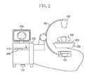
- Fig. 2 illustrates a diagnosis system using the X-ray imaging control apparatus (radiographic imaging control apparatus) according to the first exemplary embodiment of the present invention.
- Fig. 3 is a flowchart illustrating processing performed by the X-ray image processing apparatus (radiographic image processing apparatus) according to the first exemplary embodiment of the present invention.
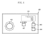
- Fig. 4 illustrates an X-ray control operation panel according to the first exemplary embodiment of the present invention.
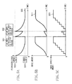
- Figs. 5A through 5C illustrate a relationship between fluoroscopic flux, noise amount, and image correction amount according to the first exemplary embodiment of the present invention.
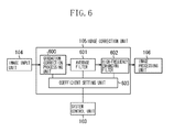
- Fig. 6 is a block diagram illustrating a detailed arrangement of an image correction unit in the X-ray image processing apparatus (radiographic image processing apparatus) according to the first exemplary embodiment of the present invention.
- Fig. 7 is a flowchart illustrating processing performed by the X-ray image processing apparatus (radiographic image processing apparatus) according to a second exemplary embodiment of the present invention.
- Figs. 8A through 8C illustrate a relationship between fluoroscopic flux, noise amount, and image correction amount according to the second exemplary embodiment of the present invention.
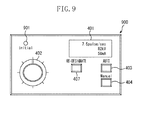
- Fig. 9 illustrates an X-ray control operation panel according to the second exemplary embodiment of the present invention.
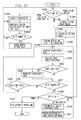
- Fig. 10 is a flowchart illustrating processing performed by the X-ray image processing apparatus (radiographic image processing apparatus) according to a third exemplary embodiment of the present invention.
- Fig. 11 illustrates an X-ray control operation panel according to the third exemplary embodiment of the present invention.
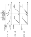
- Figs. 12A through 12C illustrate a relationship between fluoroscopic flux, noise amount, and image correction amount according to the second exemplary embodiment of the present invention.
- FIG. 1 is a block diagram illustrating an X-ray imaging control apparatus (radiographic imaging control apparatus) according to the first exemplary embodiment of the present invention.
- the X-ray imaging control apparatus illustrated in Fig. 1 includes an X-ray generation apparatus (radiant ray generation apparatus) 100, an image sensor 101, an X-ray image processing apparatus (radiographic image processing apparatus or radiation dose control apparatus) 102, a display device 108, an operation panel 110, a recording apparatus 114 , a motor 121, and a foot pedal 122.
- the X-ray generation apparatus 100 is configured to control the X-ray flux (radiation flux) of X-rays used to irradiate the subject according to a drive voltage supplied from a fluoroscopic flux control unit 115 of the X-ray image processing apparatus 102, to obtain a fluoroscopic image (an X-ray moving image) of the subject.
- a fluoroscopic flux an X-ray moving image
- the X-ray flux (radiation flux) of X-rays used to irradiate the subject is referred to as the "fluoroscopic flux.”
- the image sensor 101 detects the intensity distribution (X-ray image) of the X-rays having been transmitted through the subject, and converts it into an electric signal to obtain an X-ray image (radiographic image), i.e., fluoroscopic image, of the subject.
- a system control unit 103 of the X-ray image processing apparatus 102 controls various operations performed by the X-ray image processing apparatus 102.
- the system control unit 103 includes a central processing unit (CPU).
- CPU central processing unit
- the system control unit 103 determines the content of operational information when an operator operates the operation panel 110 or the foot pedal 122.
- the system control unit 103 performs processing for recording a change in amount of the X-ray flux (fluoroscopic flux).
- An image input unit 104 of the X-ray image processing apparatus 102 receives an X-ray image if the X-ray image is input from the image sensor 101 into the X-ray image processing apparatus 102.
- the image input unit 104 includes an analog-to-digital (A/D) converter that converts an analog signal received from the image sensor 101 (i.e., a signal relating to the X-ray image) into a digital signal.
- A/D analog-to-digital
- An image correction unit 105 of the X-ray image processing apparatus 102 performs predetermined image correction processing on the X-ray image input from the image sensor 101 via the image input unit 104.
- the image correction processing performed by the image correction unit 105 includes noise reduction processing and contour enhancement processing which are performed in a stepwise fashion.
- the image correction unit 105 performs image correction processing on an X-ray image obtained when the X-ray generation apparatus 100 irradiates the subject with X-rays.
- the X-ray image processed by the image correction unit 105 can be output to an image processing unit 106 under the control of the system control unit 103, or can be stored into the recording apparatus 114 via a system bus 119 or output to an external device via an external interface (I/F) unit 112.
- I/F external interface
- the image processing unit 106 of the X-ray image processing apparatus 102 performs predetermined image processing on an input X-ray image.
- the image processing performed by the image processing unit 106 includes diagnosis-oriented image processing and coding processing.
- the image processing unit 106 generates image data of a display image to be output to the display device 108.
- the X-ray image processed by the image processing unit 106 can be stored into the recording apparatus 114 via the system bus 119 under the control of the system control unit 103, or output to an external device via the external I/F unit 112.
- the display device 108 can display the X-ray image generated by the image processing unit 106.
- a display control unit 107 of the X-ray image processing apparatus 102 converts the image data of a display image generated by the image processing unit 106 into image data that the display device 108 can display.
- the display control unit 107 performs control for causing the display device 108 to display an image based on the image data.
- the display device 108 displays an image based on image data of the display image output from the display control unit 107.
- the display device 108 is, for example, a monitor using a cathode ray tube or a liquid crystal display.
- an operator operates the operation panel 110 while viewing an X-ray image (fluoroscopic image) displayed on the display device 108.
- An operation control unit 109 of the X-ray image processing apparatus 102 receives operational information input from an operator via the operation panel 110 or the foot pedal 122 and performs control for sending the input operational information to the system control unit 103. Furthermore, the operation control unit 109 performs control for displaying the operation status of the X-ray imaging control apparatus on a display part of the operation panel 110.
- the operation panel 110 enables an operator to perform various operations such as inputting data while viewing the display panel.
- the foot pedal 122 enables an operator to perform an ON/OFF control for the X-ray generation apparatus 100 that irradiates a subject with X-rays.
- a timer unit 111 of the X-ray image processing apparatus 102 measures elapsed time based on a control signal from the system control unit 103.
- the external I/F unit 112 of the X-ray image processing apparatus 102 is an interface that enables the X-ray image processing apparatus 102 to communicate with an external PC or an external apparatus (e.g., diagnosis apparatus).
- the external I/F unit 112 is Ethernet or USB2. 0 network interface.
- a recording apparatus control unit 113 of the X-ray image processing apparatus 102 controls the recording apparatus 114.
- the recording apparatus 114 is an external storage apparatus which can be optionally and detachably connected to the X-ray image processing apparatus 102.
- the recording apparatus 114 is, for example, a hard disk, a memory card, a flexible disk (FD), a compact disk (CD), a magnetic card, an optical card, an IC card, or a memory card.
- the fluoroscopic flux control unit 115 of the X-ray image processing apparatus 102 controls the flux of X-rays (fluoroscopic flux) when the X-ray generation apparatus 100 irradiates the subject with X-rays and changes the flux of X-rays.
- a sensor control unit 116 of the X-ray image processing apparatus 102 outputs a drive timing signal and signals relating to various setting data to the image sensor 101 and controls the operation of the image sensor 101.
- a random access memory (RAM) 117 of the X-ray image processing apparatus 102 is a memory configured to temporarily store program(s) and data supplied from an external apparatus or a flash memory 118.
- the flash memory 118 of the X-ray image processing apparatus 102 is a memory configured to store program(s) and parameters which are not changed.
- the system bus 119 of the X-ray image processing apparatus 102 enables each component to transmit and receive data and signal (s) to and from other component in the X-ray image processing apparatus 102.
- a motor control unit 120 of the X-ray image processing apparatus 102 controls the operation of each motor 121 provided in the X-ray imaging control apparatus.
- the motor 121 is, for example, a driving motor of a bed supporting the subject.
- Fig. 2 illustrates a system using the X-ray imaging control apparatus (radiographic imaging control apparatus) according to the first exemplary embodiment of the present invention.
- Fig. 2 components similar to those illustrated in Fig. 1 are denoted by the same reference numerals.
- the diagnosis system illustrated in Fig. 2 includes a C-shaped arm 201 having one end (upper end) supporting the X-ray generation apparatus 100 and the other end (lower end) supporting the image sensor 101 in an opposed or facing relationship.
- a subject 202 human body
- a bed moving apparatus 204 includes a built-in motor 121 that can slide the bed 203 along a predetermined plane.
- the diagnosis system includes a motor 121 attached to the C-shaped arm 201 and configured to drive the C-shaped arm 201.
- the operation panel 110 illustrated in Fig. 2 enables an operator to input instructions to drive the C-shaped arm 201 and the bed 203. Furthermore, the operation panel 110 includes an X-ray control operation panel 400 that enables an operator to adjust the flux of X-rays when the X-ray generation apparatus 100 irradiates a subject with X-rays.
- Fig. 3 is a flowchart illustrating processing performed by the X-ray image processing apparatus (radiographic image processing apparatus) 102 according to the first exemplary embodiment of the present invention. The processing (operations) according to this flowchart is described later.
- Fig. 4 illustrates the X-ray control operation panel 400 ( Fig. 2 ) according to the first exemplary embodiment of the present invention.
- the X-ray control operation panel 400 illustrated in Fig. 4 includes a display panel 401, a potentiometer 402, an automatic switch (AUTO SW) 403, a manual switch (MANUAL SW) 404, and a re-designation switch (RE-DESIGNATE SW) 407.
- AUTO SW automatic switch
- MANUAL SW manual switch
- RE-DESIGNATE SW re-designation switch
- the display panel 401 displays X-ray related information of the X-ray generation apparatus 100 and also can display an operational state of the system.
- the potentiometer 402 is an operation unit that enables an operator to change the fluoroscopic flux (the flux of X-rays emitted from the X-ray generation apparatus 100).
- the AUTO SW 403 enables an operator to select an automatic control of the fluoroscopic flux (the flux of X-ray emitted from the X-ray generation apparatus 100) .
- the MANUAL SW 404 enables an operator to select a manual control of the fluoroscopic flux using the potentiometer 402.
- the RE-DESIGNATE SW 407 is an operation unit that enables an operator to restore the fluoroscopic flux (the flux of X-rays emitted from the X-ray generation apparatus 100) to a predetermined level (predetermined value).
- Figs. 5A through 5C illustrate a relationship between fluoroscopic flux, noise amount, and image correction amount according to the first exemplary embodiment of the present invention.
- time 501 represents the time when the RE-DESIGNATE SW 407 is first pressed.
- time 502 represents the time when the RE-DESIGNATE SW 407 is next pressed.
- Fig. 5A illustrates the temporal change of the fluoroscopic flux 505 controlled by the system control unit 103 via the fluoroscopic flux control unit 115.
- the fluoroscopic flux 505 is restored to a predetermined upper-limit level (maximum value) 503 as illustrated in Fig. 5A . More specifically, the operator presses the RE-DESIGNATE SW 407 at the first time 501 after the fluoroscopic flux 505 has once reached a predetermined lower-limit level (minimum value) 504. Then, the operator presses the RE-DESIGNATE SW 407 again at the second time 502 before the fluoroscopic flux 505 reaches the lower-limit level (minimum value) 504. At each time, the fluoroscopic flux 505 is restored to the predetermined upper-limit level (maximum value) 503 when the operator presses the RE-DESIGNATE SW 407.
- the upper-limit level (maximum value) 503 and the lower-limit level (minimum value) 504 of the fluoroscopic flux 505 illustrated in Fig. 5A can be determined considering a portion of the subject 202 to be imaged.
- the system control unit 103 performs setting of the upper-limit level (maximum value) 503 and the lower-limit level (minimum value) 504 based on operational information input by an operator via the operation panel 110.
- the system control unit 103 performs recording (storage) of the upper-limit level (maximum value) 503 and the lower-limit level (minimum value) 504 into predetermined area (s) in the flash memory 118 (i.e., recording medium) which can be managed by the system control unit 103.
- Fig. 5B illustrates the temporal change of a noise amount 511 involved in an analog signal of the fluoroscopic image (X-ray image) output from the image sensor 101 according to the change of the fluoroscopic flux 505.
- the noise amount 511 increases monotonically according to reduction of the fluoroscopic flux 505 illustrated in Fig. 5A .
- Fig. 5C illustrates the temporal change of an image correction amount 521 for the image correction processing performed by the image correction unit 105 under the control of the system control unit 103 to decrease the noise amount 511 generated according to the change of the fluoroscopic flux 505.
- the image correction unit 105 performs processing for restoring the image correction amount to the lowest level in response to the jump of the fluoroscopic flux 505 to the upper-limit level (maximum value) 503.
- the image correction unit 105 performs processing for restoring the image correction amount to the lowest level in response to the jump of the fluoroscopic flux 505 to the upper-limit level (maximum value) 503 even if the image correction amount has an intermediate value.
- the system control unit 103 causes the image correction unit 105 to perform a control for decreasing the image correction amount in response to the jump of the fluoroscopic flux 505 to the upper-limit level (maximum value) 503.
- the above-described sequential processing illustrated in Figs. 5A through 5C can be realized by the system control unit 103 that controls setting values of the fluoroscopic flux control unit 115 and the image correction unit 105 according to time information of the timer unit 111 and an operator's instruction input via the operation panel 110.
- the flash memory 118 can store, in a predetermined area, a basic change amount applicable to the change amount of the fluoroscopic flux 505 illustrated in Fig. 5A . Furthermore, the flash memory 118 can store, in a predetermined area, a basic correction amount applicable to the image correction amount of the image correction unit 105 corresponding to the change of the fluoroscopic flux 505.
- Fig. 6 is a block diagram illustrating a detailed arrangement of the image correction unit 105 in the X-ray image processing apparatus (radiographic image processing apparatus) 102 according to the first exemplary embodiment of the present invention.
- the image correction unit 105 includes a gradation correction processing unit 600, an average filter 601, a high-frequency emphasis filter 602, and a coefficient setting unit 603.
- the gradation correction processing unit 600 performs gradation correction processing including dodging process correction for correcting the luminance level of an X-ray image (fluoroscopic image) input from the image input unit 104.
- the average filter 601 is a filter capable of removing noise.
- the high-frequency emphasis filter 602 is a filter capable of emphasis high-frequency components of an X-ray image processed by the average filter 601 if the image has a vague contour. Namely, the high-frequency emphasis filter 602 can sharpen the contour of an input X-ray image.
- the coefficient setting unit 603 sets correction coefficients supplied to the gradation correction processing unit 600, the average filter 601, and the high-frequency emphasis filter 602 to adequately adjust their processing mounts.
- the coefficient setting unit 603 performs setting of coefficients for the gradation correction processing unit 600, the average filter 601 and the high-frequency emphasis filter 602 according to an image correction amount instructed from the system control unit 103 via the system bus 119.
- the coefficient setting unit 603 performs the following processing for setting the coefficients. If the image correction amount is small, the coefficient setting unit 603 sets appropriate coefficients in such a manner that the gradation correction processing unit 600 can decrease the luminance adjustment amount to suppress luminance increase at a dark portion, the average filter 601 can decrease the processing amount to reduce the noise removal amount, and the high-frequency emphasis filter 602 can decrease the processing amount.
- the coefficient setting unit 603 sets appropriate coefficients in such a manner that the gradation correction processing unit 600 can increase the luminance adjustment amount to increase the luminance at a dark portion, the average filter 601 can increase the processing amount to increase the noise removal amount, and the high-frequency emphasis filter 602 can increase the processing amount.
- the image correction unit 105 can be configured to include a median filter.
- the high-frequency emphasis filter 602 can be replaced with a contour enhancement filter.
- step S301 the system control unit 103 detects if the AUTO SW 403 has been switched on via the operation control unit 109 if an operator presses the AUTO SW 403 when the operator performs diagnosis while viewing the display device 108.
- step S302 the system control unit 103 reads setting values relating to the fluoroscopic flux 505 (e.g., upper-limit level (maximum value) 503, lower-limit level (minimum value) 504, and change amount) from a predetermined area of the flash memory 118, and sets the read setting values to the fluoroscopic flux control unit 115. Furthermore, the system control unit 103 reads a setting value relating to the image correction amount 521 from a predetermined area of the flash memory 118, and sets the read setting values to the image correction unit 105. Furthermore, the system control unit 103 causes the timer unit 111 to start a timer operation.
- setting values relating to the fluoroscopic flux 505 e.g., upper-limit level (maximum value) 503, lower-limit level (minimum value) 504, and change amount
- the system control unit 103 reads a setting value relating to the image correction amount 521 from a predetermined area of the flash memory 118, and sets the read setting values to the image correction
- step S303 the system control unit 103 causes the fluoroscopic flux control unit 115 to decrease the fluoroscopic flux according to the basic change amount represented by the fluoroscopic flux 505 illustrated in Fig. 5A in association with the timer operation of the timer unit 111.
- the fluoroscopic flux control unit 115 instructs the X-ray generation apparatus 100 to gradually decrease the X-ray flux (fluoroscopic flux) from the predetermined upper-limit level (maximum value) 503 when the X-ray generation apparatus 100 irradiates the subject 202 with X-rays.
- This control brings preferred effects because human eyes are gradually acclimatized to an image having insufficient image quality with elapsed time.
- step S304 the system control unit 103 causes the image correction unit 105 to perform image correction processing according to the basic setting amount (rate) to decrease the fluoroscopic flux.
- the image correction unit 105 performs image correction processing based on the image correction amount 521 which increases in a stepwise fashion as illustrated in Fig. 5C . Namely, the system control unit 103 performs control for increasing the image correction amount relating to the image correction processing performed by the image correction unit 105 according to a change amount corresponding to the reduction in the fluoroscopic flux.
- step S305 the system control unit 103 determines whether the fluoroscopic flux 505 has reached the predetermined lower-limit level (minimum value) 504, while constantly monitoring the fluoroscopic flux 505 during the fluoroscopic flux reduction processing having been started in step S303.
- the predetermined lower-limit level minimum value
- step S305 If the system control unit 103 determines that the fluoroscopic flux 505 has reached the predetermined lower-limit level (minimum value) 504 (YES in step S305), the processing proceeds to step S306.
- step S306 the system control unit 103 causes the fluoroscopic flux control unit 115 to maintain the fluoroscopic flux 505 at the lower-limit level (minimum value) 504 and also causes the image correction unit 105 to maintain the image correction amount 521 at a present level.
- step S306 After completing the processing of step S306, the processing proceeds to step S307. Furthermore, if the system control unit 103 determines that the fluoroscopic flux 505 has not yet reached the predetermined lower-limit level (minimum value) 504 (NO in step S305), the processing proceeds to step S307.
- step S307 the system control unit 103 determines whether an operator operates (presses) any switch other than the AUTO SW 403 on the X-ray control operation panel 400 illustrated in Fig. 4 . If the system control unit 103 determines that a switch other than the AUTO SW 403 is not operated (pressed) (NO in step S307), the processing proceeds to step S308.
- step S308 the system control unit 103 determines whether the fluoroscopic flux 505 has reached the predetermined lower-limit level (minimum value) 504. If in step S308 it is determined that the fluoroscopic flux 505 has reached the predetermined lower-limit level (minimum value) 504 (YES in step S308), the processing returns to step S306. Furthermore, if the system control unit 103 determines that the fluoroscopic flux 505 has not yet reached the predetermined lower-limit level (minimum value) 504 (NO in step S308), the processing returns to step S303.
- step S307 If the system control unit 103 determines that a switch other than the AUTO SW 403 is operated (pressed) (YES in step S307), the processing proceeds to step S309.
- step S309 the system control unit 103 identifies the type of switch which the operator has operated (pressed) on the X-ray control operation panel 400. If in step S309 the system control unit 103 determines that the RE-DESIGNATE SW 407 is operated (pressed) by the operator, the processing proceeds to step S310.
- step S310 the system control unit 103 causes the fluoroscopic flux control unit 115 to perform resetting for restoring the fluoroscopic flux 505 to the upper-limit level (maximum value) 503.
- the fluoroscopic flux control unit 115 instructs the X-ray generation apparatus 100 to restore the X-ray flux (fluoroscopic flux) to the upper-limit level (maximum value) 503 when the X-ray generation apparatus 100 irradiates the subject 202 with X-ray.
- step S311 the system control unit 103 causes the image correction unit 105 to perform processing for restoring the image correction amount 521 ( Fig. 5C ) to an initial setting value according to the control for restoring the fluoroscopic flux 505 to the upper-limit level (maximum value) 503.
- the image correction unit 105 performs the image processing with the image correction amount fixed at the lowest level as illustrated in Fig. 5C .
- the processing returns to step S303.
- step S309 the system control unit 103 determines that the MANUAL SW 404 is operated (pressed) by the operator, the processing proceeds to step S312.
- step S312 the system control unit 103 stops automatic control processing having been performed after the operator has pressed the AUTO SW 403 and enables the operator to start a manual operation based on the processing parameters currently held. Then, the system control unit 103 terminates the processing routine according to the flowchart illustrated in Fig. 3 .
- a second exemplary embodiment of the present invention is described with reference to Figs. 7 through 9 .
- An X-ray imaging control apparatus (radiographic imaging control apparatus) according to the second exemplary embodiment of the present invention is similar in arrangement to the X-ray imaging control apparatus (radiographic imaging control apparatus) according to the first exemplary embodiment illustrated in Fig. 1 .
- Fig. 7 is a flowchart illustrating example processing performed by the X-ray image processing apparatus (radiographic image processing apparatus) 102 according to the second exemplary embodiment.
- the flowchart illustrated in Fig. 7 includes steps similar to those illustrated in Fig. 3 (first exemplary embodiment) and denoted by the same step numbers. The processing (operations) according to this flowchart is described later.
- Figs. 8A through 8C illustrate an example relationship among fluoroscopic flux, noise amount, and image correction amount according to the second exemplary embodiment of the present invention.
- some of reference numerals are identical to those illustrated in Figs. 5A through 5C (first exemplary embodiment).
- the second exemplary embodiment uses an X-ray control operation panel 900 illustrated in Fig. 9 which is different from the X-ray control operation panel 400 of the first exemplary embodiment illustrated in Fig. 4 .
- Fig. 9 illustrates an example of the X-ray control operation panel 900 according to the second exemplary embodiment.
- the X-ray control operation panel 900 illustrated in Fig. 9 includes components similar to those of the X-ray control operation panel 400 illustrated in Fig. 4 and denoted by the same reference numerals.
- the X-ray control operation panel 900 includes an initial switch (INITIAL SW) 901 in addition to the arrangement of the X-ray control operation panel 400 illustrated in Fig. 4 .
- the INITIAL SW 901 is a switch enabling an operator to change an upper-limit level (maximum value) 806 and a lower-limit level (minimum value) 807 illustrated in Fig. 8A , which are once set by an operator, to the upper-limit level (maximum value) 503 and the lower-limit level (minimum value) 504 which are predetermined initial setting values.
- time 801 represents the time when the RE-DESIGNATE SW 407 of Fig. 9 is first pressed.
- time 802 represents the time when the RE-DESIGNATE SW 407 is next pressed.
- time 803 represents time when the INITIAL SW 901 of Fig. 9 is pressed.
- Figs. 8A illustrates the temporal change of a fluoroscopic flux 805 controlled by the system control unit 103 via the fluoroscopic flux control unit 115.
- the upper-limit level (maximum value) 806 and the lower-limit level (minimum value) 807 are an upper-limit level (maximum value) and a lower-limit level (minimum value) which an operator can arbitrarily determine by performing a resetting operation.
- Fig. 8B illustrates the temporal change of a noise amount 811 involved in an analog signal of the fluoroscopic image (X-ray image) output from the image sensor 101 in contrast with the change of the fluoroscopic flux 805.
- the noise amount 811 increases monotonously according to reduction of the fluoroscopic flux 805 illustrated in Figs. 8A .
- Fig. 8C illustrates the temporal change of an image correction amount 821 for the image correction processing performed by the image correction unit 105 under the control of the system control unit 103 to decrease the noise amount 811 generated according to the change of the fluoroscopic flux 805.
- the operator presses the RE-DESIGNATE SW 407 at the first time 801 after the fluoroscopic flux 805 has once reached the predetermined lower-limit level (minimum value) 504 which is a predetermined initial setting value.
- the system control unit 103 determines that the operator permits the diagnosis being performed with the fluoroscopic flux 805 set to the predetermined lower-limit level (minimum value) 504.
- the system control unit 103 does not perform resetting for changing the lower-limit level (minimum value).
- the operator is adaptive to the image quality of a fluoroscopic image obtained while the fluoroscopic flux 805 decreases to the lower-limit level (minimum value) 504.
- the system control unit 103 performs resetting for decreasing the upper-limit level (maximum value).
- the reset value of the upper-limit level (maximum value) 806, which is determined by an operator through the reset processing, is a value smaller than the predetermined upper-limit level (maximum value) 503 and is recorded (stored) in a predetermined area of the flash memory 118 (recording medium) under the control of the system control unit 103.
- the upper-limit level (maximum value) 806, i.e., the predetermined reset value, is effective until an operator presses the INITIAL SW 901 at time 803.
- the fluoroscopic flux 805 jumps to the upper-limit level (maximum value) 806 if the RE-DESIGNATE SW 407 is pressed.
- the system control unit 103 performs resetting for increasing the lower-limit level (minimum value) 504 on the assumption that the operator has pressed the RE-DESIGNATE SW 407 because the diagnosis cannot be performed with the fluoroscopic flux 805 set to the lower-limit level (minimum value) 504.
- the fluoroscopic flux control unit 115 sets the new lower-limit level (minimum value) 807 corresponding to the fluoroscopic flux 805 at the time the RE-DESIGNATE SW 407 is pressed, while performing the processing for decreasing the fluoroscopic flux 805.
- the reset value of the lower-limit level (minimum value) 807 which is determined by an operator through the reset processing, is recorded (stored) in a predetermined area of the flash memory 118 (recording medium) under the control of the system control unit 103.
- the lower-limit level (minimum value) 807 i.e., the predetermined reset value, is effective until an operator presses the INITIAL SW 901 at time 803.
- the system control unit 103 reads the setting value relating to the image correction amount from the flash memory 118 according to the setting value relating to the fluoroscopic flux for the fluoroscopic flux control unit 115, and sets the read setting value to the image correction unit 105.
- step S301 the system control unit 103 detects if an operator presses the AUTO SW 403 when the operator performs diagnosis while viewing the display device 108.
- step S302 the system control unit 103 reads initial setting values relating to the fluoroscopic flux 805 (e.g., upper-limit level (maximum value) 503, lower-limit level (minimum value) 504, and change amount) from a predetermined area of the flash memory 118, and sets the read setting values to the fluoroscopic flux control unit 115. Furthermore, the system control unit 103 reads an initial setting value relating to the image correction amount 821 from the flash memory 118, and sets the read setting values to the image correction unit 105. Furthermore, the system control unit 103 causes the timer unit 111 to start a timer operation.
- initial setting values relating to the fluoroscopic flux 805 e.g., upper-limit level (maximum value) 503, lower-limit level (minimum value) 504, and change amount
- step S303 the system control unit 103 causes the fluoroscopic flux control unit 115 to decrease the fluoroscopic flux according to the basic change amount represented by the fluoroscopic flux 805 illustrated in Fig. 8A in association with the timer operation of the timer unit 111.
- the fluoroscopic flux control unit 115 instructs the X-ray generation apparatus 100 to gradually decrease the X-ray flux (fluoroscopic flux) from the predetermined upper-limit level (maximum value) 503 when the X-ray generation apparatus 100 irradiates the subject 202 with X-rays.
- step S304 the system control unit 103 causes the image correction unit 105 to perform image correction processing according to the basic setting amount to decrease the fluoroscopic flux.
- the image correction unit 105 performs image correction processing based on the image correction amount 821 which increases in a stepwise fashion as illustrated in Fig. 8C . Namely, the system control unit 103 performs a control for increasing the image correction amount relating to the image correction processing performed by the image correction unit 105 according to a change amount corresponding to the reduction in the fluoroscopic flux.
- step S305 the system control unit 103 determines whether the fluoroscopic flux 805 has reached the predetermined lower-limit level (minimum value) 504, while constantly monitoring the fluoroscopic flux 805 during the fluoroscopic flux reduction processing having been started in step S303.
- the predetermined lower-limit level minimum value
- step S305 If the system control unit 103 determines that the fluoroscopic flux 805 has reached the predetermined lower-limit level (minimum value) 504 (YES in step S305), the processing proceeds to step S306.
- step S306 the system control unit 103 causes the fluoroscopic flux control unit 115 to maintain the fluoroscopic flux 805 at the lower-limit level (minimum value) 504 and also causes the image correction unit 105 to maintain the image correction amount 821 at a present level.
- step S306 After completing the processing of step S306, the processing proceeds to step S307. Furthermore, if the system control unit 103 determines that the fluoroscopic flux 805 has not yet reached the predetermined lower-limit level (minimum value) 504 (NO in step S305), the processing proceeds to step S307.
- step S307 the system control unit 103 determines whether an operator operates (presses) any switch other than the AUTO SW 403 on the X-ray control operation panel 900 illustrated in Fig. 9 . If the system control unit 103 determines that a switch other than the AUTO SW 403 is not operated (pressed) (NO in step S307), the processing proceeds to step S308.
- step S308 the system control unit 103 determines whether the fluoroscopic flux 805 has reached the predetermined lower-limit level (minimum value) 504. If in step S308 it is determined that the fluoroscopic flux 805 has reached the predetermined lower-limit level (minimum value) 504 (YES in step S308), the processing returns to step S306. Furthermore, if the system control unit 103 determines that the fluoroscopic flux 805 has not yet reached the predetermined lower-limit level (minimum value) 504 (NO in step S308), the processing returns to step S303.
- step S307 If the system control unit 103 determines that a switch other than the AUTO SW 403 is operated (pressed) (YES in step S307), the processing proceeds to step S701.
- step S701 the system control unit 103 identifies the type of the switch which the operator has operated (pressed) on the X-ray control operation panel 900. If in step S701 the system control unit 103 determines that the INITIAL SW 901 is operated (pressed) by the operator, the processing returns to step S302.
- step S701 the system control unit 103 determines that the RE-DESIGNATE SW 407 is operated (pressed) by the operator, the processing proceeds to step S702.
- step S702 the system control unit 103 determines whether the fluoroscopic flux 805 has reached the lower-limit level (minimum value) 504 which is an initial setting value.
- step S703 the system control unit 103 records the lower-limit level (minimum value) 807 corresponding to the fluoroscopic flux 805 at the time the RE-DESIGNATE SW 407 is pressed into a predetermined area of the flash memory 118, while performing resetting of the lower-limit level (minimum value).
- step S703 After completing the processing of step S703, the processing proceeds to step S704. Furthermore, if the system control unit 103 determines that the fluoroscopic flux 805 has reached the predetermined lower-limit level (minimum value) 504 having been initially set (e.g., the timing 801 in illustrated in Fig. 8 ) (YES in step S702), the processing proceeds to step S704.
- the predetermined lower-limit level (minimum value) 504 having been initially set (e.g., the timing 801 in illustrated in Fig. 8 ) (YES in step S702)
- step S704 the system control unit 103 performs resetting for decreasing the upper-limit level (maximum value) 503 having been initially set to the upper-limit level (maximum value) 806. Then, the system control unit 103 records the setting value of the upper-limit level (maximum value) 806 having been reset into a predetermined area of the flash memory 118.
- step S310 the system control unit 103 causes the fluoroscopic flux control unit 115 to perform resetting for restoring the fluoroscopic flux 805 to the upper-limit level (maximum value) 806.
- the fluoroscopic flux control unit 115 instructs the X-ray generation apparatus 100 to restore the X-ray flux (fluoroscopic flux) to the upper-limit level (maximum value) 806 when the X-ray generation apparatus 100 irradiates the subject 202 with X-ray.
- step S311 the system control unit 103 causes the image correction unit 105 to perform processing for resetting the image correction amount 821 ( Fig. 8C ) to a setting value corresponding to the fluoroscopic flux 805 according to the control for restoring the fluoroscopic flux 805 to the upper-limit level (maximum value) 503.
- step S311 the processing returns to step S303.
- step S701 the system control unit 103 determines that the MANUAL SW 404 is operated (pressed) by the operator, the processing proceeds to step S312.
- step S312 the system control unit 103 stops automatic control processing having been performed after the operator has pressed the AUTO SW 403 and enables the operator to start a manual operation based on the processing parameters currently held. Then, the system control unit 103 terminates the processing routine according to the flowchart illustrated in Fig. 7 .
- a third exemplary embodiment of the present invention is described with reference to Figs. 10 through 12 .
- An X-ray imaging control apparatus (radiographic imaging control apparatus) according to the third exemplary embodiment of the present invention is similar in arrangement to the X-ray imaging control apparatus (radiographic imaging control apparatus) illustrated in Fig. 1 .
- Fig. 10 is a flowchart illustrating processing performed by the X-ray image processing apparatus (radiographic image processing apparatus) 102 according to the third exemplary embodiment of the present invention.
- the flowchart illustrated in Fig. 10 includes steps similar to those illustrated in Fig. 3 (first exemplary embodiment) and denoted by the same step numbers. The processing (operations) according to this flowchart is described later.
- the third exemplary embodiment uses an X-ray control operation panel 1100 illustrated in Fig. 11 which is different from the X-ray control operation panel 400 of the first exemplary embodiment illustrated in Fig. 4 (or the X-ray control operation panel 900 of the second exemplary embodiment illustrated in Fig. 9 ).
- Fig. 11 illustrates an example of the X-ray control operation panel 1100 according to the third exemplary embodiment.
- the X-ray control operation panel 1100 illustrated in Fig. 11 includes components similar to those of the X-ray control operation panel 900 illustrated in Fig. 9 and denoted by the same reference numerals. More specifically, the X-ray control operation panel 1100 according to the third exemplary embodiment includes various switches 1101 through 1105 in addition to the arrangement of the X-ray control operation panel 900 illustrated in Fig. 9 .
- An upper-limit switch (UPPER-LIMIT SW) 1101 is a switch enabling an operator to manually change the upper-limit level (maximum value).
- a lower-limit switch (LOWER-LIMIT SW) 1102 is a switch enabling an operator to manually change the lower-limit level (minimum value).
- An input switch (input SW) 1103 is a switch enabling an operator to set a new upper-limit level changed by manipulating the UPPER-LIMIT SW 1101 or a new lower-limit level changed by manipulating the LOWER-LIMIT SW 1102.
- a memory-1 switch (MEMORY-1 SW) 1104 and a memory-2 switch (MEMORY-2 SW) 1105 are switches enabling an operator to record each of the updated values of the upper-limit level and the lower-limit level.
- Figs. 12A through 12C illustrate a relationship between fluoroscopic flux, noise amount, and image correction amount according to the third exemplary embodiment of the present invention.
- timing 1201 represents time when the RE-DESIGNATE SW 407 is first pressed.
- timing 1202 represents time when the RE-DESIGNATE SW 407 is next pressed.
- Fig. 12A illustrates the temporal change of a fluoroscopic flux 1205 controlled by the system control unit 103 via the fluoroscopic flux control unit 115. If an operator presses the RE-DESIGNATE SW 407, the fluoroscopic flux 1205 is restored to a predetermined upper-limit level (maximum value) 1203 as illustrated in Fig. 12A .
- the operator presses the RE-DESIGNATE SW 407 at the first time 1201 after the fluoroscopic flux 505 has once reached the predetermined lower-limit level (minimum value) 1204. Then, the operator presses the RE-DESIGNATE SW 407 again at the second time 502 before the fluoroscopic flux 1205 reaches the lower-limit level (minimum value) 504. At each time, the fluoroscopic flux 1205 is restored to the predetermined upper-limit level (maximum value) 1203 when the operator presses the RE-DESIGNATE SW 407.
- the upper-limit level (maximum value) 1203 and the lower-limit level (minimum value) 1204 of the fluoroscopic flux 1205 illustrated in Figs. 12A can be determined considering a portion of the subject 202 to be imaged, or can be arbitrarily set by an operator. If the setting processing considering the portion to be imaged is completed, the system control unit 103 performs recording (storage) of the upper-limit level (maximum value) 1203 and the lower-limit level (minimum value) 1204 into a predetermined area of the flash memory 118 (i.e., recording medium) which can be managed by the system control unit 103.
- the system control unit 103 performs recording (storage) of the set values of the upper-limit level and the lower-limit level into an area of the flash memory 118 (i.e., recording medium) which is different from the recording area for the setting values determined according to the portion of the subject 202 to be imaged.
- Fig. 12B illustrates the temporal change of a noise amount 1211 involved in an analog signal of the fluoroscopic image (X-ray image) output from the image sensor 101 in association with the change of the fluoroscopic flux 1205.
- the noise amount 1211 increases monotonically according to the reduction of the fluoroscopic flux 1205 illustrated in Fig. 12A .
- Fig. 12C illustrates the temporal change of an image correction amount 1221 for the image correction processing performed by the image correction unit 105 under the control of the system control unit 103 to decrease the noise amount 1211 generated according to the change of the fluoroscopic flux 1205.
- the image correction unit 105 performs processing for restoring the image correction amount to the lowest level in response to the jump of the fluoroscopic flux 1205 to the upper-limit level (maximum value) 503.
- the image correction unit 105 performs processing for restoring the image correction amount to the lowest level in response to the jump of the fluoroscopic flux 1205 to the upper-limit level (maximum value) 1203 even if the image correction amount has an intermediate value. If an operator presses the RE-DESIGNATE SW 407, the system control unit 103 causes the image correction unit 105 to perform a control for decreasing the image correction amount in response to the jump of the fluoroscopic flux 1205 to the upper-limit level (maximum value) 1203.
- the above-described sequential processing illustrated in Figs. 12A through 12C can be realized by the system control unit 103 that controls setting values of the fluoroscopic flux control unit 115 and the image correction unit 105 according to time information of the timer unit 111 and an operator's instruction input via the operation panel 110.
- the flash memory 118 can store, in a predetermined area, a basic change amount applicable to the change amount of the fluoroscopic flux 1205 illustrated in Fig. 12A .
- the flash memory 118 can store, in a predetermined area, a basic correction amount applicable to the image correction amount 1221 of the image correction unit 105 corresponding to the change of the fluoroscopic flux 1205.
- An example method for recording setting values of the upper-limit level (maximum value) and the lower-limit level (minimum value) based on the MEMORY-1 SW 1104 and the MEMORY-2 SW 1105 is described below. Furthermore, an example method for setting temporary values of the upper-limit level (maximum value) and the lower-limit level (minimum value) is described below.
- step S1001 the system control unit 103 determines whether an operator has operated (pressed) any switch on the X-ray control operation panel 1100 illustrated in Fig. 11 . More specifically, in step S1001, the system control unit 103 determines whether an operator has operated the UPPER-LIMIT SW 1101 or the LOWER-LIMIT SW 1102 on the X-ray control operation panel 1100 illustrated in Fig. 11 . Furthermore, the system control unit 103 determines whether the AUTO SW 403 is operated. Moreover, the system control unit 103 determines whether the AUTO SW 403 is operated after the memory SW (MEMORY-1 SW 1104 or MEMORY-2 SW 1105) is operated. If any other switch is operated, the system control unit 103 maintains a standby state in step S1001.
- step S1001 the system control unit 103 determines that the UPPER-LIMIT SW 1101 or the LOWER-LIMIT SW 1102 is operated (pressed), the processing proceeds to step S1002.
- step S1002 the system control unit 103 detects an operated amount of the potentiometer 402 if an operator adjusts the upper-limit level (maximum value) or the lower-limit level (minimum value) while viewing the fluoroscopic flux value displayed on the display panel 401
- step S1003 the system control unit 103 temporarily records the upper-limit level (maximum value) or the lower-limit level (minimum value) of the fluoroscopic flux adjusted in step S1002 in response to detection of turning-on of the input SW1103. More specifically, the system control unit 103 temporarily records the upper-limit level (maximum value) or the lower-limit level (minimum value) of the fluoroscopic flux at the time the input SW1103 is pressed into a temporary recording area of the flash memory 118.
- the above-described processing (operations) represents a control flow realizing the method for setting temporary upper-limit level (maximum value) and the lower-limit level (minimum value).
- the system control unit 103 determines whether an operator has operated (pressed) the memory SW (MEMORY-1 SW 1104 or MEMORY-2 SW 1105).
- step S1004 If the system control unit 103 determines that the memory SW (MEMORY-1 SW 1104 or MEMORY-2 SW 1105) is operated (pressed) by the operator (YES in step S1004), the processing proceeds to step S1005.
- step S1005 the system control unit 103 performs processing for transferring the setting value temporarily stored in the temporary recording area of the flash memory 118 in step S1003 into a corresponding memory area of the same flash memory 118 according to the type of the memory SW.
- the system control unit 103 records the setting value temporarily stored in the temporary recording area of the flash memory 118 in step S1003 into a memory-1 area of the flash memory 118. Furthermore, if an operator operates (presses) the MEMORY-2 SW 1105, the system control unit 103 records the setting value temporarily stored in the temporary recording area of the flash memory 118 in step S1003 into a memory-2 area of the flash memory 118.
- step S1004 If the memory SW (MEMORY-1 SW 1104 or MEMORY-2 SW 1105) is not operated (pressed) by the operator (NO in step S1004), the processing returns to step S1001.
- the above-described processing (operations) represents a control flow realizing the method for recording a setting value of the upper-limit level (maximum value) or the lower-limit level (minimum value) in response to detection of turning-on of the MEMORY-1 SW 1104 or the MEMORY-2 SW 1105.
- the third exemplary embodiment performs automatic control processing (operations), an automatic control with temporarily set values of the upper-limit level and the lower-limit level, and an automatic control using the memory.
- step S1001 the system control unit 103 determines that the AUTO SW 403 is operated (pressed) under the condition that all of the UPPER-LIMIT SW 1101, the LOWER-LIMIT SW 1102, and the memory SW (MEMORY-1 SW 1104 or MEMORY-2 SW 1105) are not operated (pressed), the processing proceeds to step S1007.
- step S1007 the system control unit 103 reads setting values of the upper-limit level and the lower-limit level for the fluoroscopic flux determined beforehand based on a portion to be imaged from a predetermined area of the flash memory 118. Then, the system control unit 103 sets the read setting values of the upper-limit level and the lower-limit level for the fluoroscopic flux to the fluoroscopic flux control unit 115, which correspond to the upper-limit level (maximum value) 1203 and the lower-limit level (minimum value) 1204 illustrated in Fig. 12A .
- step S1007 the system control unit 103 reads the setting value relating to the image correction amount 1221 from a predetermined area of the flash memory 118 and sets the read setting values to the image correction unit 105. Furthermore, the system control unit 103 causes the timer unit 111 to start a timer operation.
- step S1001 the system control unit 103 determines that the UPPER-LIMIT SW 1101 or the LOWER-LIMIT SW 1102 is operated (pressed)
- the system control unit 103 executes the processing of steps S1002 and S1003. Then, if in step S1004 the system control unit 103 determines that the memory SW (MEMORY-1 SW 1104 or MEMORY-2 SW 1105) is not operated (pressed), the processing returns to step S1001. If in step S1001 the system control unit 103 determines that the AUTO SW 403 is operated (pressed), the processing proceeds to step S1007.
- step S1007 the system control unit 103 reads the setting value of the upper-limit level (maximum value) or the lower-limit level (minimum value) temporarily stored into the temporary recording area of the flash memory 118 in step S1003. Then, the system control unit 103 sets the setting value of the upper-limit level or the lower-limit level temporarily stored into the flash memory 118 in step S1003 to the fluoroscopic flux control unit 115, which correspond to the upper-limit level (maximum value) 1203 and the lower-limit level (minimum value) 1204 illustrated in Fig. 12A .
- the system control unit 103 prioritizes the setting value of the upper-limit level or the lower-limit level temporarily stored into the flash memory 118 over the setting value of the upper-limit level or the lower-limit level determined beforehand based on a portion to be imaged.
- the flash memory 118 can store temporary setting values of both the upper-limit level and the lower-limit level if the system control unit 103 repetitively performs the processing of step S1003.
- the system control unit 103 can perform setting of the upper-limit level (maximum value) 1203 and the lower-limit level (minimum value) 1204 based on these setting values. Furthermore, in step S1007, the system control unit 103 reads the setting value relating to the image correction amount 1221 from the predetermined area of the flash memory 118 and sets the read setting value to the image correction unit 105. Furthermore, the system control unit 103 causes the timer unit 111 to start a timer operation.
- step S1001 the system control unit 103 determines that the AUTO SW 403 is operated (pressed) after the memory SW (MEMORY-1 SW 1104 or MEMORY-2 SW 1105) is operated (pressed), the processing proceeds to step S1006.
- step S1006 the system control unit 103 reads the setting value of the upper-limit level (maximum value) or the lower-limit level (minimum value) which has been stored into the memory area (memory-1 area or memory-2 area) of the flash memory 118 in step S1005.
- the system control unit 103 reads the latest setting value.
- step S1006 the system control unit 103 instructs setting value change based on the read setting value. Then, the processing proceeds to step S1007.
- step S1007 the system control unit 103 sets the setting value of the upper-limit level or the lower-limit level read out of the memory area of the flash memory 118 in step S1006 to the fluoroscopic flux control unit 115, which correspond to the upper-limit level (maximum value) 1203 and the lower-limit level (minimum value) 1204 illustrated in Fig. 12A .
- the system control unit 103 prioritizes the setting value of the upper-limit level or the lower-limit level temporarily stored into the flash memory 118 over the setting value of the upper-limit level or the lower-limit level determined beforehand based on a portion to be imaged. Furthermore, in step S1007, the system control unit 103 reads the setting value relating to the image correction amount 1221 from the predetermined area of the flash memory 118 and sets the read setting value to the image correction unit 105. Furthermore, the system control unit 103 causes the timer unit 111 to start a timer operation.
- step S1007 the system control unit 103 executes the processing of steps S303 through S308 illustrated in Fig. 3 .
- step S307 the system control unit 103 determines that an operator has operated (pressed) any switch other than the AUTO SW 403, such as RE-DESIGNATE SW 407, MANUAL SW 404, or INITIAL SW 901, on the X-ray control operation panel 1100, the processing proceeds to step S1008.
- any switch other than the AUTO SW 403, such as RE-DESIGNATE SW 407, MANUAL SW 404, or INITIAL SW 901, on the X-ray control operation panel 1100 the processing proceeds to step S1008.
- step S1008 the system control unit 103 identifies the type of the switch which the operator has operated (pressed) on the X-ray control operation panel 1100. If in step S1008 the system control unit 103 determines that the RE-DESIGNATE SW 407 is operated (pressed) by the operator, the system control unit 103 executes the processing of steps S310 and S311 described with reference to Fig. 3 . Then, the processing returns to step S304.
- step S1008 the system control unit 103 determines that the MANUAL SW 404 is operated (pressed) by the operator, the system control unit 103 executes the processing of step S312 described with reference to Fig. 3 and terminates the processing routine according to the flowchart illustrated in Fig. 10 .
- step S1008 the system control unit 103 determines that the INITIAL SW 901 is operated (pressed) by the operator, the processing proceeds to step S1009.
- step S1009 the system control unit 103 performs processing for initializing the setting values having been set in step S1007. Then, the processing returns to step S1001.
- the system control unit 103 restarts the processing of step S1001 and the following steps.
- the processing proceeds from step S1009 to step S1001.
- the processing can proceed from step S1009 to step S1007.
- the setting value used in step S1007 is the setting value determined when only the AUTO SW 403 is operated (pressed).
- the X-ray flux starts falling immediately after initiation of the X-ray imaging operation.
- the system control unit 103 can be configured to start decreasing the X-ray flux when a predetermined time has elapsed after initiation of the X-ray imaging operation.
- software program code for realizing the functions of the above-described exemplary embodiments can be supplied to a system or an apparatus including various devices.
- a computer or CPU or micro-processing unit (MPU) in the system or the apparatus can execute the program to operate the devices to realize the functions of the above-described exemplary embodiments.
- the present invention encompasses the program code installable on a computer when the functions or processes of the exemplary embodiments can be realized by the computer.
- the functional components constituting the X-ray image processing apparatus 102 illustrated in Fig. 1 which relate to each exemplary embodiment, as well as the steps of Figs. 3 , 7 and 10 which realize the X-ray image processing method, can be realized by a computer that performs various operations based on software program(s) stored in a random access memory (RAM) or a read only memory (ROM).
- RAM random access memory
- ROM read only memory
- the present invention encompasses such program(s) and a computer-readable storage medium storing the program(s).
- the present invention encompasses supplying the program(s) to a computer with a storage (or recording) medium storing the program code.
- a storage medium supplying the program(s) can be any one of a floppy disk, a hard disk, an optical disk, a magneto-optical (MO) disk, a compact disk - ROM (CD-ROM), a CD-recordable (CD-R), a CD-rewritable (CD-RW), a magnetic tape, a nonvolatile memory card, a ROM, and a DVD (DVD-ROM, DVD-R).
- a transmission medium of the program(s) is, for example, any communication medium available for a computer network (any one of LAN, WAN (e.g., Internet), and wireless communication network) system that can transmit a carrier signal including program information.
- the communication medium is a wired communication medium (e.g., optical fiber) or a wireless communication medium.
- the present invention is not limited to a computer executing supplied program(s) to realize the X-ray image processing apparatus 102 according to the exemplary embodiments.
- an operating system (OS) or other application software running on a computer can realize the functions of the X-ray image processing apparatus 102 according to the exemplary embodiments
- the program code read out of a storage medium can be written into a memory of a function expansion board equipped in a computer or into a memory of a function expansion unit connected to the computer.
- a CPU provided on the function expansion board or the function expansion unit can execute part or the whole of the processing so that the functions of the X-ray image processing apparatus 102 according to the above-described exemplary embodiments can be realized.
- the X-ray image processing apparatus 102 includes the fluoroscopic flux control unit 115 that can change the X-ray flux when the X-ray generation apparatus 100 irradiates the subject 202 with X-rays.
- the image correction unit 105 performs image correction processing on an X-ray image obtained when the X-ray generation apparatus 100 irradiates the subject 202 with X-rays.
- the system control unit 103 causes the image correction unit 105 to change an image correction amount for the image correction processing if the fluoroscopic flux control unit 115 changes the X-ray flux.
- the X-ray image processing apparatus 102 can obtain an X-ray image having an image quality sufficient for performing a diagnosis, while minimizing the X-ray flux of X-ray emitted toward the subject 202.
- the X-ray image processing apparatus 102 according to the exemplary embodiments can prevent the image quality of an X-ray image from deteriorating without excessively irradiating the subject 202 with X-rays.
Landscapes
- Life Sciences & Earth Sciences (AREA)
- Health & Medical Sciences (AREA)
- Engineering & Computer Science (AREA)
- Medical Informatics (AREA)
- Physics & Mathematics (AREA)
- Optics & Photonics (AREA)
- General Health & Medical Sciences (AREA)
- High Energy & Nuclear Physics (AREA)
- Veterinary Medicine (AREA)
- Nuclear Medicine, Radiotherapy & Molecular Imaging (AREA)
- Public Health (AREA)
- Pathology (AREA)
- Radiology & Medical Imaging (AREA)
- Biomedical Technology (AREA)
- Heart & Thoracic Surgery (AREA)
- Molecular Biology (AREA)
- Surgery (AREA)
- Animal Behavior & Ethology (AREA)
- Biophysics (AREA)
- General Physics & Mathematics (AREA)
- Theoretical Computer Science (AREA)
- Apparatus For Radiation Diagnosis (AREA)
Abstract
Description
- The present invention relates to a radiographic imaging control apparatus for controlling a radiant ray generation apparatus configured to irradiate a subject with radiant rays.
- A conventional radiographic imaging system can detect a transmission distribution of radiant rays (represented by X-rays) having been transmitted through a subject, and can be used in a medical field to help diagnose by imaging the inside of a human body.
- As discussed in Japanese Patent Application Laid-Open No.
2005-124975 - Furthermore, as discussed in Japanese Patent Application Laid-Open No.
2004-77709 - However, in the imaging of a human body based on transmission of X-ray, it is inevitable that the human body is significantly exposed to the X-ray. In general, detailed diagnosis of a human body requires a higher level of X-rays and increases the risk of damaging the human body with the X-rays. On the other hand, if the level of X-ray dose is lowered for the purpose of suppressing radiation damage, the image quality of a radiographic image deteriorates due to generation and increase of noise. Thus, the X-ray procedure can cause a problem for a medical purposes.
- The above-described conventional system is configured to control the X-ray dose to an appropriate level according to the purpose of a radiographic imaging operation. However, according to the above-described conventional system, the X-ray dose is fixed to a predetermined level in an initial state and, after the system starts a radiographic imaging operation, an operator is allowed to manually change the X-ray dose. Therefore, the subject may be unwittingly exposed to a higher level of X-ray for a long time.
- Conventional radiographic imaging systems cannot prevent the image quality of a radiographic image from deteriorating without excessively irradiating the subject.
- Exemplary embodiments of the present invention are directed to a radiographic imaging control apparatus capable of preventing the image quality of a radiographic image from deteriorating without excessively irradiating a subject.
- The present invention in its first aspect provides a radiographic imaging control apparatus as specified in
claims 1 to 4. - The present invention in its second aspect provides a method for controlling a radiographic imaging control apparatus as specified in claims 6 to 9.
- The present invention also provides a radiant ray imaging apparatus as specified in claim 5.
- Further features and aspects of the present invention will become apparent from the following detailed description of exemplary embodiments with reference to the attached drawings.
- The accompanying drawings, which are incorporated in and constitute a part of the specification, illustrate exemplary embodiments and features of the invention and, together with the description, serve to explain at least some of the principles of the invention.
-
Fig. 1 is a block diagram illustrating an X-ray imaging control apparatus (radiographic imaging control apparatus) according to a first exemplary embodiment of the present invention. -
Fig. 2 illustrates a diagnosis system using the X-ray imaging control apparatus (radiographic imaging control apparatus) according to the first exemplary embodiment of the present invention. -
Fig. 3 is a flowchart illustrating processing performed by the X-ray image processing apparatus (radiographic image processing apparatus) according to the first exemplary embodiment of the present invention. -
Fig. 4 illustrates an X-ray control operation panel according to the first exemplary embodiment of the present invention. -
Figs. 5A through 5C illustrate a relationship between fluoroscopic flux, noise amount, and image correction amount according to the first exemplary embodiment of the present invention. -
Fig. 6 is a block diagram illustrating a detailed arrangement of an image correction unit in the X-ray image processing apparatus (radiographic image processing apparatus) according to the first exemplary embodiment of the present invention. -
Fig. 7 is a flowchart illustrating processing performed by the X-ray image processing apparatus (radiographic image processing apparatus) according to a second exemplary embodiment of the present invention. -
Figs. 8A through 8C illustrate a relationship between fluoroscopic flux, noise amount, and image correction amount according to the second exemplary embodiment of the present invention. -
Fig. 9 illustrates an X-ray control operation panel according to the second exemplary embodiment of the present invention. -
Fig. 10 is a flowchart illustrating processing performed by the X-ray image processing apparatus (radiographic image processing apparatus) according to a third exemplary embodiment of the present invention. -
Fig. 11 illustrates an X-ray control operation panel according to the third exemplary embodiment of the present invention. -
Figs. 12A through 12C illustrate a relationship between fluoroscopic flux, noise amount, and image correction amount according to the second exemplary embodiment of the present invention. - The following description of exemplary embodiments is illustrative in nature and is in no way intended to limit the invention, its application, or uses. Processes, techniques, apparatus, and systems as known by one of ordinary skill in the art are intended to be part of the enabling description where appropriate. It is noted that throughout the specification, similar reference numerals and letters refer to similar items in the following figures, and thus once an item is described in one figure, it may not be discussed for following figures. Exemplary embodiments will be described in detail with reference to the drawings. The radiant rays used in the following exemplary embodiments of the present invention are X-rays. However, other radiant rays (electromagnetic wave represented by visible light, α-rays, β-rays, γ-rays, etc.) can be also used in the present invention.
- A first exemplary embodiment of the present invention is now described with reference to
Figs. 1 through 6 .Fig. 1 is a block diagram illustrating an X-ray imaging control apparatus (radiographic imaging control apparatus) according to the first exemplary embodiment of the present invention. - The X-ray imaging control apparatus illustrated in
Fig. 1 includes an X-ray generation apparatus (radiant ray generation apparatus) 100, animage sensor 101, an X-ray image processing apparatus (radiographic image processing apparatus or radiation dose control apparatus) 102, adisplay device 108, anoperation panel 110, arecording apparatus 114 , amotor 121, and afoot pedal 122. - The
X-ray generation apparatus 100 is configured to control the X-ray flux (radiation flux) of X-rays used to irradiate the subject according to a drive voltage supplied from a fluoroscopicflux control unit 115 of the X-rayimage processing apparatus 102, to obtain a fluoroscopic image (an X-ray moving image) of the subject. In the following description, the X-ray flux (radiation flux) of X-rays used to irradiate the subject is referred to as the "fluoroscopic flux." - The
image sensor 101 detects the intensity distribution (X-ray image) of the X-rays having been transmitted through the subject, and converts it into an electric signal to obtain an X-ray image (radiographic image), i.e., fluoroscopic image, of the subject. - A
system control unit 103 of the X-rayimage processing apparatus 102 controls various operations performed by the X-rayimage processing apparatus 102. Thesystem control unit 103 includes a central processing unit (CPU). For example, thesystem control unit 103 determines the content of operational information when an operator operates theoperation panel 110 or thefoot pedal 122. Furthermore, thesystem control unit 103 performs processing for recording a change in amount of the X-ray flux (fluoroscopic flux). - An
image input unit 104 of the X-rayimage processing apparatus 102 receives an X-ray image if the X-ray image is input from theimage sensor 101 into the X-rayimage processing apparatus 102. Theimage input unit 104 includes an analog-to-digital (A/D) converter that converts an analog signal received from the image sensor 101 (i.e., a signal relating to the X-ray image) into a digital signal. - An
image correction unit 105 of the X-rayimage processing apparatus 102 performs predetermined image correction processing on the X-ray image input from theimage sensor 101 via theimage input unit 104. The image correction processing performed by theimage correction unit 105 includes noise reduction processing and contour enhancement processing which are performed in a stepwise fashion. - The
image correction unit 105 performs image correction processing on an X-ray image obtained when theX-ray generation apparatus 100 irradiates the subject with X-rays. The X-ray image processed by theimage correction unit 105 can be output to animage processing unit 106 under the control of thesystem control unit 103, or can be stored into therecording apparatus 114 via asystem bus 119 or output to an external device via an external interface (I/F)unit 112. - The
image processing unit 106 of the X-rayimage processing apparatus 102 performs predetermined image processing on an input X-ray image. The image processing performed by theimage processing unit 106 includes diagnosis-oriented image processing and coding processing. Theimage processing unit 106 generates image data of a display image to be output to thedisplay device 108. The X-ray image processed by theimage processing unit 106 can be stored into therecording apparatus 114 via thesystem bus 119 under the control of thesystem control unit 103, or output to an external device via the external I/F unit 112. Thedisplay device 108 can display the X-ray image generated by theimage processing unit 106. - A
display control unit 107 of the X-rayimage processing apparatus 102 converts the image data of a display image generated by theimage processing unit 106 into image data that thedisplay device 108 can display. Thedisplay control unit 107 performs control for causing thedisplay device 108 to display an image based on the image data. - The
display device 108 displays an image based on image data of the display image output from thedisplay control unit 107. Thedisplay device 108 is, for example, a monitor using a cathode ray tube or a liquid crystal display. For example, an operator operates theoperation panel 110 while viewing an X-ray image (fluoroscopic image) displayed on thedisplay device 108. - An
operation control unit 109 of the X-rayimage processing apparatus 102 receives operational information input from an operator via theoperation panel 110 or thefoot pedal 122 and performs control for sending the input operational information to thesystem control unit 103. Furthermore, theoperation control unit 109 performs control for displaying the operation status of the X-ray imaging control apparatus on a display part of theoperation panel 110. - The
operation panel 110 enables an operator to perform various operations such as inputting data while viewing the display panel. Thefoot pedal 122 enables an operator to perform an ON/OFF control for theX-ray generation apparatus 100 that irradiates a subject with X-rays. - A
timer unit 111 of the X-rayimage processing apparatus 102 measures elapsed time based on a control signal from thesystem control unit 103. - The external I/
F unit 112 of the X-rayimage processing apparatus 102 is an interface that enables the X-rayimage processing apparatus 102 to communicate with an external PC or an external apparatus (e.g., diagnosis apparatus). For example, the external I/F unit 112 is Ethernet or USB2. 0 network interface. - A recording
apparatus control unit 113 of the X-rayimage processing apparatus 102 controls therecording apparatus 114. - The
recording apparatus 114 is an external storage apparatus which can be optionally and detachably connected to the X-rayimage processing apparatus 102. Therecording apparatus 114 is, for example, a hard disk, a memory card, a flexible disk (FD), a compact disk (CD), a magnetic card, an optical card, an IC card, or a memory card. - The fluoroscopic
flux control unit 115 of the X-rayimage processing apparatus 102 controls the flux of X-rays (fluoroscopic flux) when theX-ray generation apparatus 100 irradiates the subject with X-rays and changes the flux of X-rays. - A
sensor control unit 116 of the X-rayimage processing apparatus 102 outputs a drive timing signal and signals relating to various setting data to theimage sensor 101 and controls the operation of theimage sensor 101. - A random access memory (RAM) 117 of the X-ray
image processing apparatus 102 is a memory configured to temporarily store program(s) and data supplied from an external apparatus or aflash memory 118. Theflash memory 118 of the X-rayimage processing apparatus 102 is a memory configured to store program(s) and parameters which are not changed. - The
system bus 119 of the X-rayimage processing apparatus 102 enables each component to transmit and receive data and signal (s) to and from other component in the X-rayimage processing apparatus 102. - A
motor control unit 120 of the X-rayimage processing apparatus 102 controls the operation of eachmotor 121 provided in the X-ray imaging control apparatus. - The
motor 121 is, for example, a driving motor of a bed supporting the subject. -
Fig. 2 illustrates a system using the X-ray imaging control apparatus (radiographic imaging control apparatus) according to the first exemplary embodiment of the present invention. InFig. 2 , components similar to those illustrated inFig. 1 are denoted by the same reference numerals. - The diagnosis system illustrated in
Fig. 2 includes a C-shapedarm 201 having one end (upper end) supporting theX-ray generation apparatus 100 and the other end (lower end) supporting theimage sensor 101 in an opposed or facing relationship. A subject 202 (human body), when mounted on abed 203, can be positioned on a straight line connecting theX-ray generation apparatus 100 and theimage sensor 101. Abed moving apparatus 204 includes a built-inmotor 121 that can slide thebed 203 along a predetermined plane. Furthermore, although not illustrated inFig. 2 , the diagnosis system includes amotor 121 attached to the C-shapedarm 201 and configured to drive the C-shapedarm 201. - The
operation panel 110 illustrated inFig. 2 enables an operator to input instructions to drive the C-shapedarm 201 and thebed 203. Furthermore, theoperation panel 110 includes an X-raycontrol operation panel 400 that enables an operator to adjust the flux of X-rays when theX-ray generation apparatus 100 irradiates a subject with X-rays. -
Fig. 3 is a flowchart illustrating processing performed by the X-ray image processing apparatus (radiographic image processing apparatus) 102 according to the first exemplary embodiment of the present invention. The processing (operations) according to this flowchart is described later. -
Fig. 4 illustrates the X-ray control operation panel 400 (Fig. 2 ) according to the first exemplary embodiment of the present invention. The X-raycontrol operation panel 400 illustrated inFig. 4 includes adisplay panel 401, apotentiometer 402, an automatic switch (AUTO SW) 403, a manual switch (MANUAL SW) 404, and a re-designation switch (RE-DESIGNATE SW) 407. - The
display panel 401 displays X-ray related information of theX-ray generation apparatus 100 and also can display an operational state of the system. Thepotentiometer 402 is an operation unit that enables an operator to change the fluoroscopic flux (the flux of X-rays emitted from the X-ray generation apparatus 100). TheAUTO SW 403 enables an operator to select an automatic control of the fluoroscopic flux (the flux of X-ray emitted from the X-ray generation apparatus 100) . TheMANUAL SW 404 enables an operator to select a manual control of the fluoroscopic flux using thepotentiometer 402. TheRE-DESIGNATE SW 407 is an operation unit that enables an operator to restore the fluoroscopic flux (the flux of X-rays emitted from the X-ray generation apparatus 100) to a predetermined level (predetermined value). -
Figs. 5A through 5C illustrate a relationship between fluoroscopic flux, noise amount, and image correction amount according to the first exemplary embodiment of the present invention. InFigs. 5A through 5C ,time 501 represents the time when theRE-DESIGNATE SW 407 is first pressed. Furthermore,time 502 represents the time when theRE-DESIGNATE SW 407 is next pressed. -
Fig. 5A illustrates the temporal change of thefluoroscopic flux 505 controlled by thesystem control unit 103 via the fluoroscopicflux control unit 115. If an operator presses theRE-DESIGNATE SW 407, thefluoroscopic flux 505 is restored to a predetermined upper-limit level (maximum value) 503 as illustrated inFig. 5A . More specifically, the operator presses theRE-DESIGNATE SW 407 at thefirst time 501 after thefluoroscopic flux 505 has once reached a predetermined lower-limit level (minimum value) 504. Then, the operator presses theRE-DESIGNATE SW 407 again at thesecond time 502 before thefluoroscopic flux 505 reaches the lower-limit level (minimum value) 504. At each time, thefluoroscopic flux 505 is restored to the predetermined upper-limit level (maximum value) 503 when the operator presses theRE-DESIGNATE SW 407. - In this example, the upper-limit level (maximum value) 503 and the lower-limit level (minimum value) 504 of the
fluoroscopic flux 505 illustrated inFig. 5A can be determined considering a portion of the subject 202 to be imaged. For example, thesystem control unit 103 performs setting of the upper-limit level (maximum value) 503 and the lower-limit level (minimum value) 504 based on operational information input by an operator via theoperation panel 110. Furthermore, after completing the setting processing, thesystem control unit 103 performs recording (storage) of the upper-limit level (maximum value) 503 and the lower-limit level (minimum value) 504 into predetermined area (s) in the flash memory 118 (i.e., recording medium) which can be managed by thesystem control unit 103. -
Fig. 5B illustrates the temporal change of anoise amount 511 involved in an analog signal of the fluoroscopic image (X-ray image) output from theimage sensor 101 according to the change of thefluoroscopic flux 505. As apparent fromFig. 5B , thenoise amount 511 increases monotonically according to reduction of thefluoroscopic flux 505 illustrated inFig. 5A . -
Fig. 5C illustrates the temporal change of animage correction amount 521 for the image correction processing performed by theimage correction unit 105 under the control of thesystem control unit 103 to decrease thenoise amount 511 generated according to the change of thefluoroscopic flux 505. - As illustrated in
Fig. 5C , at thetime 501 when theRE-DESIGNATE SW 407 is first pressed, theimage correction unit 105 performs processing for restoring the image correction amount to the lowest level in response to the jump of thefluoroscopic flux 505 to the upper-limit level (maximum value) 503. Similarly, at thetime 502 when theRE-DESIGNATE SW 407 is next pressed, theimage correction unit 105 performs processing for restoring the image correction amount to the lowest level in response to the jump of thefluoroscopic flux 505 to the upper-limit level (maximum value) 503 even if the image correction amount has an intermediate value. Namely, if an operator presses theRE-DESIGNATE SW 407, thesystem control unit 103 causes theimage correction unit 105 to perform a control for decreasing the image correction amount in response to the jump of thefluoroscopic flux 505 to the upper-limit level (maximum value) 503. - The above-described sequential processing illustrated in
Figs. 5A through 5C can be realized by thesystem control unit 103 that controls setting values of the fluoroscopicflux control unit 115 and theimage correction unit 105 according to time information of thetimer unit 111 and an operator's instruction input via theoperation panel 110. Theflash memory 118 can store, in a predetermined area, a basic change amount applicable to the change amount of thefluoroscopic flux 505 illustrated inFig. 5A . Furthermore, theflash memory 118 can store, in a predetermined area, a basic correction amount applicable to the image correction amount of theimage correction unit 105 corresponding to the change of thefluoroscopic flux 505. -
Fig. 6 is a block diagram illustrating a detailed arrangement of theimage correction unit 105 in the X-ray image processing apparatus (radiographic image processing apparatus) 102 according to the first exemplary embodiment of the present invention. - As illustrated in
Fig. 6 , theimage correction unit 105 includes a gradationcorrection processing unit 600, anaverage filter 601, a high-frequency emphasis filter 602, and acoefficient setting unit 603. - The gradation
correction processing unit 600 performs gradation correction processing including dodging process correction for correcting the luminance level of an X-ray image (fluoroscopic image) input from theimage input unit 104. Theaverage filter 601 is a filter capable of removing noise. The high-frequency emphasis filter 602 is a filter capable of emphasis high-frequency components of an X-ray image processed by theaverage filter 601 if the image has a vague contour. Namely, the high-frequency emphasis filter 602 can sharpen the contour of an input X-ray image. Thecoefficient setting unit 603 sets correction coefficients supplied to the gradationcorrection processing unit 600, theaverage filter 601, and the high-frequency emphasis filter 602 to adequately adjust their processing mounts. - More specifically, the
coefficient setting unit 603 performs setting of coefficients for the gradationcorrection processing unit 600, theaverage filter 601 and the high-frequency emphasis filter 602 according to an image correction amount instructed from thesystem control unit 103 via thesystem bus 119. - For example, the
coefficient setting unit 603 performs the following processing for setting the coefficients. If the image correction amount is small, thecoefficient setting unit 603 sets appropriate coefficients in such a manner that the gradationcorrection processing unit 600 can decrease the luminance adjustment amount to suppress luminance increase at a dark portion, theaverage filter 601 can decrease the processing amount to reduce the noise removal amount, and the high-frequency emphasis filter 602 can decrease the processing amount. - Furthermore, if the image correction amount is large, the
coefficient setting unit 603 sets appropriate coefficients in such a manner that the gradationcorrection processing unit 600 can increase the luminance adjustment amount to increase the luminance at a dark portion, theaverage filter 601 can increase the processing amount to increase the noise removal amount, and the high-frequency emphasis filter 602 can increase the processing amount. - The noise removal arrangement illustrated in
Fig. 6 is a mere example. According to another exemplary embodiment, theimage correction unit 105 can be configured to include a median filter. The high-frequency emphasis filter 602 can be replaced with a contour enhancement filter. - Next, example processing (operations) performed by the X-ray image processing apparatus (radiographic image processing apparatus) 102 according to the first exemplary embodiment of the present invention is described with reference to a flowchart illustrated in
Fig. 3 . - In step S301, the
system control unit 103 detects if theAUTO SW 403 has been switched on via theoperation control unit 109 if an operator presses theAUTO SW 403 when the operator performs diagnosis while viewing thedisplay device 108. - In step S302, the
system control unit 103 reads setting values relating to the fluoroscopic flux 505 (e.g., upper-limit level (maximum value) 503, lower-limit level (minimum value) 504, and change amount) from a predetermined area of theflash memory 118, and sets the read setting values to the fluoroscopicflux control unit 115. Furthermore, thesystem control unit 103 reads a setting value relating to theimage correction amount 521 from a predetermined area of theflash memory 118, and sets the read setting values to theimage correction unit 105. Furthermore, thesystem control unit 103 causes thetimer unit 111 to start a timer operation. - In step S303, the
system control unit 103 causes the fluoroscopicflux control unit 115 to decrease the fluoroscopic flux according to the basic change amount represented by thefluoroscopic flux 505 illustrated inFig. 5A in association with the timer operation of thetimer unit 111. The fluoroscopicflux control unit 115 instructs theX-ray generation apparatus 100 to gradually decrease the X-ray flux (fluoroscopic flux) from the predetermined upper-limit level (maximum value) 503 when theX-ray generation apparatus 100 irradiates the subject 202 with X-rays. This control brings preferred effects because human eyes are gradually acclimatized to an image having insufficient image quality with elapsed time. - In step S304, the
system control unit 103 causes theimage correction unit 105 to perform image correction processing according to the basic setting amount (rate) to decrease the fluoroscopic flux. Theimage correction unit 105 performs image correction processing based on theimage correction amount 521 which increases in a stepwise fashion as illustrated inFig. 5C . Namely, thesystem control unit 103 performs control for increasing the image correction amount relating to the image correction processing performed by theimage correction unit 105 according to a change amount corresponding to the reduction in the fluoroscopic flux. - In step S305, the
system control unit 103 determines whether thefluoroscopic flux 505 has reached the predetermined lower-limit level (minimum value) 504, while constantly monitoring thefluoroscopic flux 505 during the fluoroscopic flux reduction processing having been started in step S303. - If the
system control unit 103 determines that thefluoroscopic flux 505 has reached the predetermined lower-limit level (minimum value) 504 (YES in step S305), the processing proceeds to step S306. - In step S306, the
system control unit 103 causes the fluoroscopicflux control unit 115 to maintain thefluoroscopic flux 505 at the lower-limit level (minimum value) 504 and also causes theimage correction unit 105 to maintain theimage correction amount 521 at a present level. - After completing the processing of step S306, the processing proceeds to step S307. Furthermore, if the
system control unit 103 determines that thefluoroscopic flux 505 has not yet reached the predetermined lower-limit level (minimum value) 504 (NO in step S305), the processing proceeds to step S307. - In step S307, the
system control unit 103 determines whether an operator operates (presses) any switch other than theAUTO SW 403 on the X-raycontrol operation panel 400 illustrated inFig. 4 . If thesystem control unit 103 determines that a switch other than theAUTO SW 403 is not operated (pressed) (NO in step S307), the processing proceeds to step S308. - In step S308, the
system control unit 103 determines whether thefluoroscopic flux 505 has reached the predetermined lower-limit level (minimum value) 504. If in step S308 it is determined that thefluoroscopic flux 505 has reached the predetermined lower-limit level (minimum value) 504 (YES in step S308), the processing returns to step S306. Furthermore, if thesystem control unit 103 determines that thefluoroscopic flux 505 has not yet reached the predetermined lower-limit level (minimum value) 504 (NO in step S308), the processing returns to step S303. - If the
system control unit 103 determines that a switch other than theAUTO SW 403 is operated (pressed) (YES in step S307), the processing proceeds to step S309. - In step S309, the
system control unit 103 identifies the type of switch which the operator has operated (pressed) on the X-raycontrol operation panel 400. If in step S309 thesystem control unit 103 determines that theRE-DESIGNATE SW 407 is operated (pressed) by the operator, the processing proceeds to step S310. - In step S310, the
system control unit 103 causes the fluoroscopicflux control unit 115 to perform resetting for restoring thefluoroscopic flux 505 to the upper-limit level (maximum value) 503. The fluoroscopicflux control unit 115 instructs theX-ray generation apparatus 100 to restore the X-ray flux (fluoroscopic flux) to the upper-limit level (maximum value) 503 when theX-ray generation apparatus 100 irradiates the subject 202 with X-ray. - In step S311, the
system control unit 103 causes theimage correction unit 105 to perform processing for restoring the image correction amount 521 (Fig. 5C ) to an initial setting value according to the control for restoring thefluoroscopic flux 505 to the upper-limit level (maximum value) 503. Theimage correction unit 105 performs the image processing with the image correction amount fixed at the lowest level as illustrated inFig. 5C . After completing the processing of step S311, the processing returns to step S303. - If in step S309 the
system control unit 103 determines that theMANUAL SW 404 is operated (pressed) by the operator, the processing proceeds to step S312. - In step S312, the
system control unit 103 stops automatic control processing having been performed after the operator has pressed theAUTO SW 403 and enables the operator to start a manual operation based on the processing parameters currently held. Then, thesystem control unit 103 terminates the processing routine according to the flowchart illustrated inFig. 3 . - A second exemplary embodiment of the present invention is described with reference to
Figs. 7 through 9 . An X-ray imaging control apparatus (radiographic imaging control apparatus) according to the second exemplary embodiment of the present invention is similar in arrangement to the X-ray imaging control apparatus (radiographic imaging control apparatus) according to the first exemplary embodiment illustrated inFig. 1 . -
Fig. 7 is a flowchart illustrating example processing performed by the X-ray image processing apparatus (radiographic image processing apparatus) 102 according to the second exemplary embodiment. The flowchart illustrated inFig. 7 includes steps similar to those illustrated inFig. 3 (first exemplary embodiment) and denoted by the same step numbers. The processing (operations) according to this flowchart is described later. -
Figs. 8A through 8C illustrate an example relationship among fluoroscopic flux, noise amount, and image correction amount according to the second exemplary embodiment of the present invention. InFigs. 8A through 8C , some of reference numerals are identical to those illustrated inFigs. 5A through 5C (first exemplary embodiment). - Furthermore, the second exemplary embodiment uses an X-ray
control operation panel 900 illustrated inFig. 9 which is different from the X-raycontrol operation panel 400 of the first exemplary embodiment illustrated inFig. 4 . -
Fig. 9 illustrates an example of the X-raycontrol operation panel 900 according to the second exemplary embodiment. The X-raycontrol operation panel 900 illustrated inFig. 9 includes components similar to those of the X-raycontrol operation panel 400 illustrated inFig. 4 and denoted by the same reference numerals. - More specifically, the X-ray
control operation panel 900 according to the second exemplary embodiment includes an initial switch (INITIAL SW) 901 in addition to the arrangement of the X-raycontrol operation panel 400 illustrated inFig. 4 . TheINITIAL SW 901 is a switch enabling an operator to change an upper-limit level (maximum value) 806 and a lower-limit level (minimum value) 807 illustrated inFig. 8A , which are once set by an operator, to the upper-limit level (maximum value) 503 and the lower-limit level (minimum value) 504 which are predetermined initial setting values. - In
Figs. 8A through 8C ,time 801 represents the time when theRE-DESIGNATE SW 407 ofFig. 9 is first pressed. Furthermore,time 802 represents the time when theRE-DESIGNATE SW 407 is next pressed. Moreover, thetime 803 represents time when theINITIAL SW 901 ofFig. 9 is pressed. -
Figs. 8A illustrates the temporal change of afluoroscopic flux 805 controlled by thesystem control unit 103 via the fluoroscopicflux control unit 115. The upper-limit level (maximum value) 806 and the lower-limit level (minimum value) 807 are an upper-limit level (maximum value) and a lower-limit level (minimum value) which an operator can arbitrarily determine by performing a resetting operation. -
Fig. 8B illustrates the temporal change of anoise amount 811 involved in an analog signal of the fluoroscopic image (X-ray image) output from theimage sensor 101 in contrast with the change of thefluoroscopic flux 805. As apparent fromFig. 8B , thenoise amount 811 increases monotonously according to reduction of thefluoroscopic flux 805 illustrated inFigs. 8A . -
Fig. 8C illustrates the temporal change of animage correction amount 821 for the image correction processing performed by theimage correction unit 105 under the control of thesystem control unit 103 to decrease thenoise amount 811 generated according to the change of thefluoroscopic flux 805. - More specifically, the operator presses the
RE-DESIGNATE SW 407 at thefirst time 801 after thefluoroscopic flux 805 has once reached the predetermined lower-limit level (minimum value) 504 which is a predetermined initial setting value. In this case, thesystem control unit 103 determines that the operator permits the diagnosis being performed with thefluoroscopic flux 805 set to the predetermined lower-limit level (minimum value) 504. Thesystem control unit 103 does not perform resetting for changing the lower-limit level (minimum value). - In this case, the operator is adaptive to the image quality of a fluoroscopic image obtained while the
fluoroscopic flux 805 decreases to the lower-limit level (minimum value) 504. Thesystem control unit 103 performs resetting for decreasing the upper-limit level (maximum value). The reset value of the upper-limit level (maximum value) 806, which is determined by an operator through the reset processing, is a value smaller than the predetermined upper-limit level (maximum value) 503 and is recorded (stored) in a predetermined area of the flash memory 118 (recording medium) under the control of thesystem control unit 103. The upper-limit level (maximum value) 806, i.e., the predetermined reset value, is effective until an operator presses theINITIAL SW 901 attime 803. According to this exemplary embodiment, thefluoroscopic flux 805 jumps to the upper-limit level (maximum value) 806 if theRE-DESIGNATE SW 407 is pressed. - Then, the operator presses the
RE-DESIGNATE SW 407 again at thesecond time 802 before thefluoroscopic flux 805 reaches the predetermined lower-limit level (minimum value) 504 having been initially set. In this case, thesystem control unit 103 performs resetting for increasing the lower-limit level (minimum value) 504 on the assumption that the operator has pressed theRE-DESIGNATE SW 407 because the diagnosis cannot be performed with thefluoroscopic flux 805 set to the lower-limit level (minimum value) 504. - The fluoroscopic
flux control unit 115 sets the new lower-limit level (minimum value) 807 corresponding to thefluoroscopic flux 805 at the time theRE-DESIGNATE SW 407 is pressed, while performing the processing for decreasing thefluoroscopic flux 805. The reset value of the lower-limit level (minimum value) 807, which is determined by an operator through the reset processing, is recorded (stored) in a predetermined area of the flash memory 118 (recording medium) under the control of thesystem control unit 103. The lower-limit level (minimum value) 807, i.e., the predetermined reset value, is effective until an operator presses theINITIAL SW 901 attime 803. - The
system control unit 103 reads the setting value relating to the image correction amount from theflash memory 118 according to the setting value relating to the fluoroscopic flux for the fluoroscopicflux control unit 115, and sets the read setting value to theimage correction unit 105. - Next, example processing (operations) performed by the X-ray image processing apparatus (radiographic image processing apparatus) 102 according to the second exemplary embodiment is described below with reference to the flowchart illustrated in
Fig. 7 . - In step S301, the
system control unit 103 detects if an operator presses theAUTO SW 403 when the operator performs diagnosis while viewing thedisplay device 108. - In step S302, the
system control unit 103 reads initial setting values relating to the fluoroscopic flux 805 (e.g., upper-limit level (maximum value) 503, lower-limit level (minimum value) 504, and change amount) from a predetermined area of theflash memory 118, and sets the read setting values to the fluoroscopicflux control unit 115. Furthermore, thesystem control unit 103 reads an initial setting value relating to theimage correction amount 821 from theflash memory 118, and sets the read setting values to theimage correction unit 105. Furthermore, thesystem control unit 103 causes thetimer unit 111 to start a timer operation. - In step S303, the
system control unit 103 causes the fluoroscopicflux control unit 115 to decrease the fluoroscopic flux according to the basic change amount represented by thefluoroscopic flux 805 illustrated inFig. 8A in association with the timer operation of thetimer unit 111. The fluoroscopicflux control unit 115 instructs theX-ray generation apparatus 100 to gradually decrease the X-ray flux (fluoroscopic flux) from the predetermined upper-limit level (maximum value) 503 when theX-ray generation apparatus 100 irradiates the subject 202 with X-rays. - In step S304, the
system control unit 103 causes theimage correction unit 105 to perform image correction processing according to the basic setting amount to decrease the fluoroscopic flux. Theimage correction unit 105 performs image correction processing based on theimage correction amount 821 which increases in a stepwise fashion as illustrated inFig. 8C . Namely, thesystem control unit 103 performs a control for increasing the image correction amount relating to the image correction processing performed by theimage correction unit 105 according to a change amount corresponding to the reduction in the fluoroscopic flux. - In step S305, the
system control unit 103 determines whether thefluoroscopic flux 805 has reached the predetermined lower-limit level (minimum value) 504, while constantly monitoring thefluoroscopic flux 805 during the fluoroscopic flux reduction processing having been started in step S303. - If the
system control unit 103 determines that thefluoroscopic flux 805 has reached the predetermined lower-limit level (minimum value) 504 (YES in step S305), the processing proceeds to step S306. - In step S306, the
system control unit 103 causes the fluoroscopicflux control unit 115 to maintain thefluoroscopic flux 805 at the lower-limit level (minimum value) 504 and also causes theimage correction unit 105 to maintain theimage correction amount 821 at a present level. - After completing the processing of step S306, the processing proceeds to step S307. Furthermore, if the
system control unit 103 determines that thefluoroscopic flux 805 has not yet reached the predetermined lower-limit level (minimum value) 504 (NO in step S305), the processing proceeds to step S307. - In step S307, the
system control unit 103 determines whether an operator operates (presses) any switch other than theAUTO SW 403 on the X-raycontrol operation panel 900 illustrated inFig. 9 . If thesystem control unit 103 determines that a switch other than theAUTO SW 403 is not operated (pressed) (NO in step S307), the processing proceeds to step S308. - In step S308, the
system control unit 103 determines whether thefluoroscopic flux 805 has reached the predetermined lower-limit level (minimum value) 504. If in step S308 it is determined that thefluoroscopic flux 805 has reached the predetermined lower-limit level (minimum value) 504 (YES in step S308), the processing returns to step S306. Furthermore, if thesystem control unit 103 determines that thefluoroscopic flux 805 has not yet reached the predetermined lower-limit level (minimum value) 504 (NO in step S308), the processing returns to step S303. - If the
system control unit 103 determines that a switch other than theAUTO SW 403 is operated (pressed) (YES in step S307), the processing proceeds to step S701. - In step S701, the
system control unit 103 identifies the type of the switch which the operator has operated (pressed) on the X-raycontrol operation panel 900. If in step S701 thesystem control unit 103 determines that theINITIAL SW 901 is operated (pressed) by the operator, the processing returns to step S302. - If in step S701 the
system control unit 103 determines that theRE-DESIGNATE SW 407 is operated (pressed) by the operator, the processing proceeds to step S702. In step S702, thesystem control unit 103 determines whether thefluoroscopic flux 805 has reached the lower-limit level (minimum value) 504 which is an initial setting value. - If the
system control unit 103 determines that thefluoroscopic flux 805 has not yet reached the lower-limit level (minimum value) 504 having been initially set (e.g., thetiming 802 illustrated inFig. 8 ) (NO in step S702), the processing proceeds to step S703. In step S703, thesystem control unit 103 records the lower-limit level (minimum value) 807 corresponding to thefluoroscopic flux 805 at the time theRE-DESIGNATE SW 407 is pressed into a predetermined area of theflash memory 118, while performing resetting of the lower-limit level (minimum value). - After completing the processing of step S703, the processing proceeds to step S704. Furthermore, if the
system control unit 103 determines that thefluoroscopic flux 805 has reached the predetermined lower-limit level (minimum value) 504 having been initially set (e.g., thetiming 801 in illustrated inFig. 8 ) (YES in step S702), the processing proceeds to step S704. - In step S704, the
system control unit 103 performs resetting for decreasing the upper-limit level (maximum value) 503 having been initially set to the upper-limit level (maximum value) 806. Then, thesystem control unit 103 records the setting value of the upper-limit level (maximum value) 806 having been reset into a predetermined area of theflash memory 118. - In step S310, the
system control unit 103 causes the fluoroscopicflux control unit 115 to perform resetting for restoring thefluoroscopic flux 805 to the upper-limit level (maximum value) 806. The fluoroscopicflux control unit 115 instructs theX-ray generation apparatus 100 to restore the X-ray flux (fluoroscopic flux) to the upper-limit level (maximum value) 806 when theX-ray generation apparatus 100 irradiates the subject 202 with X-ray. - In step S311, the
system control unit 103 causes theimage correction unit 105 to perform processing for resetting the image correction amount 821 (Fig. 8C ) to a setting value corresponding to thefluoroscopic flux 805 according to the control for restoring thefluoroscopic flux 805 to the upper-limit level (maximum value) 503. After completing the processing of step S311, the processing returns to step S303. - If in step S701 the
system control unit 103 determines that theMANUAL SW 404 is operated (pressed) by the operator, the processing proceeds to step S312. - In step S312, the
system control unit 103 stops automatic control processing having been performed after the operator has pressed theAUTO SW 403 and enables the operator to start a manual operation based on the processing parameters currently held. Then, thesystem control unit 103 terminates the processing routine according to the flowchart illustrated inFig. 7 . - A third exemplary embodiment of the present invention is described with reference to
Figs. 10 through 12 . An X-ray imaging control apparatus (radiographic imaging control apparatus) according to the third exemplary embodiment of the present invention is similar in arrangement to the X-ray imaging control apparatus (radiographic imaging control apparatus) illustrated inFig. 1 . -
Fig. 10 is a flowchart illustrating processing performed by the X-ray image processing apparatus (radiographic image processing apparatus) 102 according to the third exemplary embodiment of the present invention. The flowchart illustrated inFig. 10 includes steps similar to those illustrated inFig. 3 (first exemplary embodiment) and denoted by the same step numbers. The processing (operations) according to this flowchart is described later. - Furthermore, the third exemplary embodiment uses an X-ray
control operation panel 1100 illustrated inFig. 11 which is different from the X-raycontrol operation panel 400 of the first exemplary embodiment illustrated inFig. 4 (or the X-raycontrol operation panel 900 of the second exemplary embodiment illustrated inFig. 9 ). -
Fig. 11 illustrates an example of the X-raycontrol operation panel 1100 according to the third exemplary embodiment. The X-raycontrol operation panel 1100 illustrated inFig. 11 includes components similar to those of the X-raycontrol operation panel 900 illustrated inFig. 9 and denoted by the same reference numerals. More specifically, the X-raycontrol operation panel 1100 according to the third exemplary embodiment includesvarious switches 1101 through 1105 in addition to the arrangement of the X-raycontrol operation panel 900 illustrated inFig. 9 . - An upper-limit switch (UPPER-LIMIT SW) 1101 is a switch enabling an operator to manually change the upper-limit level (maximum value). A lower-limit switch (LOWER-LIMIT SW) 1102 is a switch enabling an operator to manually change the lower-limit level (minimum value). An input switch (input SW) 1103 is a switch enabling an operator to set a new upper-limit level changed by manipulating the UPPER-
LIMIT SW 1101 or a new lower-limit level changed by manipulating the LOWER-LIMIT SW 1102. A memory-1 switch (MEMORY-1 SW) 1104 and a memory-2 switch (MEMORY-2 SW) 1105 are switches enabling an operator to record each of the updated values of the upper-limit level and the lower-limit level. -
Figs. 12A through 12C illustrate a relationship between fluoroscopic flux, noise amount, and image correction amount according to the third exemplary embodiment of the present invention. InFigs. 12A through 12C ,timing 1201 represents time when theRE-DESIGNATE SW 407 is first pressed. Furthermore,timing 1202 represents time when theRE-DESIGNATE SW 407 is next pressed. -
Fig. 12A illustrates the temporal change of afluoroscopic flux 1205 controlled by thesystem control unit 103 via the fluoroscopicflux control unit 115. If an operator presses theRE-DESIGNATE SW 407, thefluoroscopic flux 1205 is restored to a predetermined upper-limit level (maximum value) 1203 as illustrated inFig. 12A . - More specifically, the operator presses the
RE-DESIGNATE SW 407 at thefirst time 1201 after thefluoroscopic flux 505 has once reached the predetermined lower-limit level (minimum value) 1204. Then, the operator presses theRE-DESIGNATE SW 407 again at thesecond time 502 before thefluoroscopic flux 1205 reaches the lower-limit level (minimum value) 504. At each time, thefluoroscopic flux 1205 is restored to the predetermined upper-limit level (maximum value) 1203 when the operator presses theRE-DESIGNATE SW 407. - The upper-limit level (maximum value) 1203 and the lower-limit level (minimum value) 1204 of the
fluoroscopic flux 1205 illustrated inFigs. 12A can be determined considering a portion of the subject 202 to be imaged, or can be arbitrarily set by an operator. If the setting processing considering the portion to be imaged is completed, thesystem control unit 103 performs recording (storage) of the upper-limit level (maximum value) 1203 and the lower-limit level (minimum value) 1204 into a predetermined area of the flash memory 118 (i.e., recording medium) which can be managed by thesystem control unit 103. - Furthermore, if the setting processing based on an operator's manual operation is completed, the
system control unit 103 performs recording (storage) of the set values of the upper-limit level and the lower-limit level into an area of the flash memory 118 (i.e., recording medium) which is different from the recording area for the setting values determined according to the portion of the subject 202 to be imaged. -
Fig. 12B illustrates the temporal change of anoise amount 1211 involved in an analog signal of the fluoroscopic image (X-ray image) output from theimage sensor 101 in association with the change of thefluoroscopic flux 1205. As is apparent fromFig. 12B , thenoise amount 1211 increases monotonically according to the reduction of thefluoroscopic flux 1205 illustrated inFig. 12A . -
Fig. 12C illustrates the temporal change of animage correction amount 1221 for the image correction processing performed by theimage correction unit 105 under the control of thesystem control unit 103 to decrease thenoise amount 1211 generated according to the change of thefluoroscopic flux 1205. - As illustrated in
Fig. 12C , at thetime 1201 when theRE-DESIGNATE SW 407 is first pressed, theimage correction unit 105 performs processing for restoring the image correction amount to the lowest level in response to the jump of thefluoroscopic flux 1205 to the upper-limit level (maximum value) 503. - Similarly, at the
time 1202 when theRE-DESIGNATE SW 407 is next pressed, theimage correction unit 105 performs processing for restoring the image correction amount to the lowest level in response to the jump of thefluoroscopic flux 1205 to the upper-limit level (maximum value) 1203 even if the image correction amount has an intermediate value. If an operator presses theRE-DESIGNATE SW 407, thesystem control unit 103 causes theimage correction unit 105 to perform a control for decreasing the image correction amount in response to the jump of thefluoroscopic flux 1205 to the upper-limit level (maximum value) 1203. - The above-described sequential processing illustrated in
Figs. 12A through 12C can be realized by thesystem control unit 103 that controls setting values of the fluoroscopicflux control unit 115 and theimage correction unit 105 according to time information of thetimer unit 111 and an operator's instruction input via theoperation panel 110. Theflash memory 118 can store, in a predetermined area, a basic change amount applicable to the change amount of thefluoroscopic flux 1205 illustrated inFig. 12A . Furthermore, theflash memory 118 can store, in a predetermined area, a basic correction amount applicable to theimage correction amount 1221 of theimage correction unit 105 corresponding to the change of thefluoroscopic flux 1205. - Next, example processing (operations) performed by the X-ray image processing apparatus (radiographic image processing apparatus) 102 according to the third exemplary embodiment is described with reference to the flowchart illustrated in
Fig. 10 . - An example method for recording setting values of the upper-limit level (maximum value) and the lower-limit level (minimum value) based on the MEMORY-1
SW 1104 and the MEMORY-2SW 1105 is described below. Furthermore, an example method for setting temporary values of the upper-limit level (maximum value) and the lower-limit level (minimum value) is described below. - In step S1001, the
system control unit 103 determines whether an operator has operated (pressed) any switch on the X-raycontrol operation panel 1100 illustrated inFig. 11 . More specifically, in step S1001, thesystem control unit 103 determines whether an operator has operated the UPPER-LIMIT SW 1101 or the LOWER-LIMIT SW 1102 on the X-raycontrol operation panel 1100 illustrated inFig. 11 . Furthermore, thesystem control unit 103 determines whether theAUTO SW 403 is operated. Moreover, thesystem control unit 103 determines whether theAUTO SW 403 is operated after the memory SW (MEMORY-1SW 1104 or MEMORY-2 SW 1105) is operated. If any other switch is operated, thesystem control unit 103 maintains a standby state in step S1001. - If in step S1001 the
system control unit 103 determines that the UPPER-LIMIT SW 1101 or the LOWER-LIMIT SW 1102 is operated (pressed), the processing proceeds to step S1002. In step S1002, thesystem control unit 103 detects an operated amount of thepotentiometer 402 if an operator adjusts the upper-limit level (maximum value) or the lower-limit level (minimum value) while viewing the fluoroscopic flux value displayed on thedisplay panel 401 - In step S1003, the
system control unit 103 temporarily records the upper-limit level (maximum value) or the lower-limit level (minimum value) of the fluoroscopic flux adjusted in step S1002 in response to detection of turning-on of the input SW1103. More specifically, thesystem control unit 103 temporarily records the upper-limit level (maximum value) or the lower-limit level (minimum value) of the fluoroscopic flux at the time the input SW1103 is pressed into a temporary recording area of theflash memory 118. - The above-described processing (operations) represents a control flow realizing the method for setting temporary upper-limit level (maximum value) and the lower-limit level (minimum value). After the input SW1103 is operated (pressed), in step S1004, the
system control unit 103 determines whether an operator has operated (pressed) the memory SW (MEMORY-1SW 1104 or MEMORY-2 SW 1105). - If the
system control unit 103 determines that the memory SW (MEMORY-1SW 1104 or MEMORY-2 SW 1105) is operated (pressed) by the operator (YES in step S1004), the processing proceeds to step S1005. - In step S1005, the
system control unit 103 performs processing for transferring the setting value temporarily stored in the temporary recording area of theflash memory 118 in step S1003 into a corresponding memory area of thesame flash memory 118 according to the type of the memory SW. - More specifically, if an operator operates (presses) the MEMORY-1
SW 1104, thesystem control unit 103 records the setting value temporarily stored in the temporary recording area of theflash memory 118 in step S1003 into a memory-1 area of theflash memory 118. Furthermore, if an operator operates (presses) the MEMORY-2SW 1105, thesystem control unit 103 records the setting value temporarily stored in the temporary recording area of theflash memory 118 in step S1003 into a memory-2 area of theflash memory 118. - If the memory SW (MEMORY-1
SW 1104 or MEMORY-2 SW 1105) is not operated (pressed) by the operator (NO in step S1004), the processing returns to step S1001. - The above-described processing (operations) represents a control flow realizing the method for recording a setting value of the upper-limit level (maximum value) or the lower-limit level (minimum value) in response to detection of turning-on of the MEMORY-1
SW 1104 or the MEMORY-2SW 1105. - The third exemplary embodiment performs automatic control processing (operations), an automatic control with temporarily set values of the upper-limit level and the lower-limit level, and an automatic control using the memory.
- If in step S1001 the
system control unit 103 determines that theAUTO SW 403 is operated (pressed) under the condition that all of the UPPER-LIMIT SW 1101, the LOWER-LIMIT SW 1102, and the memory SW (MEMORY-1SW 1104 or MEMORY-2 SW 1105) are not operated (pressed), the processing proceeds to step S1007. - In step S1007, the
system control unit 103 reads setting values of the upper-limit level and the lower-limit level for the fluoroscopic flux determined beforehand based on a portion to be imaged from a predetermined area of theflash memory 118. Then, thesystem control unit 103 sets the read setting values of the upper-limit level and the lower-limit level for the fluoroscopic flux to the fluoroscopicflux control unit 115, which correspond to the upper-limit level (maximum value) 1203 and the lower-limit level (minimum value) 1204 illustrated inFig. 12A . - In step S1007, the
system control unit 103 reads the setting value relating to theimage correction amount 1221 from a predetermined area of theflash memory 118 and sets the read setting values to theimage correction unit 105. Furthermore, thesystem control unit 103 causes thetimer unit 111 to start a timer operation. - If in step S1001 the
system control unit 103 determines that the UPPER-LIMIT SW 1101 or the LOWER-LIMIT SW 1102 is operated (pressed), thesystem control unit 103 executes the processing of steps S1002 and S1003. Then, if in step S1004 thesystem control unit 103 determines that the memory SW (MEMORY-1SW 1104 or MEMORY-2 SW 1105) is not operated (pressed), the processing returns to step S1001. If in step S1001 thesystem control unit 103 determines that theAUTO SW 403 is operated (pressed), the processing proceeds to step S1007. - In this case, in step S1007, the
system control unit 103 reads the setting value of the upper-limit level (maximum value) or the lower-limit level (minimum value) temporarily stored into the temporary recording area of theflash memory 118 in step S1003. Then, thesystem control unit 103 sets the setting value of the upper-limit level or the lower-limit level temporarily stored into theflash memory 118 in step S1003 to the fluoroscopicflux control unit 115, which correspond to the upper-limit level (maximum value) 1203 and the lower-limit level (minimum value) 1204 illustrated inFig. 12A . - The
system control unit 103 prioritizes the setting value of the upper-limit level or the lower-limit level temporarily stored into theflash memory 118 over the setting value of the upper-limit level or the lower-limit level determined beforehand based on a portion to be imaged. For example, theflash memory 118 can store temporary setting values of both the upper-limit level and the lower-limit level if thesystem control unit 103 repetitively performs the processing of step S1003. - In this case, the
system control unit 103 can perform setting of the upper-limit level (maximum value) 1203 and the lower-limit level (minimum value) 1204 based on these setting values. Furthermore, in step S1007, thesystem control unit 103 reads the setting value relating to theimage correction amount 1221 from the predetermined area of theflash memory 118 and sets the read setting value to theimage correction unit 105. Furthermore, thesystem control unit 103 causes thetimer unit 111 to start a timer operation. - Furthermore, if in step S1001 the
system control unit 103 determines that theAUTO SW 403 is operated (pressed) after the memory SW (MEMORY-1SW 1104 or MEMORY-2 SW 1105) is operated (pressed), the processing proceeds to step S1006. - In step S1006, the
system control unit 103 reads the setting value of the upper-limit level (maximum value) or the lower-limit level (minimum value) which has been stored into the memory area (memory-1 area or memory-2 area) of theflash memory 118 in step S1005. In this case, if the setting value of the upper-limit level (maximum value) or the lower-limit level (minimum value) is recorded in both the memory-1 area and the memory-2 area, thesystem control unit 103 reads the latest setting value. Then, in step S1006, thesystem control unit 103 instructs setting value change based on the read setting value. Then, the processing proceeds to step S1007. - In this case, in step S1007, the
system control unit 103 sets the setting value of the upper-limit level or the lower-limit level read out of the memory area of theflash memory 118 in step S1006 to the fluoroscopicflux control unit 115, which correspond to the upper-limit level (maximum value) 1203 and the lower-limit level (minimum value) 1204 illustrated inFig. 12A . - The
system control unit 103 prioritizes the setting value of the upper-limit level or the lower-limit level temporarily stored into theflash memory 118 over the setting value of the upper-limit level or the lower-limit level determined beforehand based on a portion to be imaged. Furthermore, in step S1007, thesystem control unit 103 reads the setting value relating to theimage correction amount 1221 from the predetermined area of theflash memory 118 and sets the read setting value to theimage correction unit 105. Furthermore, thesystem control unit 103 causes thetimer unit 111 to start a timer operation. - After completing the processing of step S1007, the
system control unit 103 executes the processing of steps S303 through S308 illustrated inFig. 3 . - Then, if in step S307 the
system control unit 103 determines that an operator has operated (pressed) any switch other than theAUTO SW 403, such asRE-DESIGNATE SW 407,MANUAL SW 404, orINITIAL SW 901, on the X-raycontrol operation panel 1100, the processing proceeds to step S1008. - In step S1008, the
system control unit 103 identifies the type of the switch which the operator has operated (pressed) on the X-raycontrol operation panel 1100. If in step S1008 thesystem control unit 103 determines that theRE-DESIGNATE SW 407 is operated (pressed) by the operator, thesystem control unit 103 executes the processing of steps S310 and S311 described with reference toFig. 3 . Then, the processing returns to step S304. - Furthermore, if in step S1008 the
system control unit 103 determines that theMANUAL SW 404 is operated (pressed) by the operator, thesystem control unit 103 executes the processing of step S312 described with reference toFig. 3 and terminates the processing routine according to the flowchart illustrated inFig. 10 . - Furthermore, if in step S1008 the
system control unit 103 determines that theINITIAL SW 901 is operated (pressed) by the operator, the processing proceeds to step S1009. In step S1009, thesystem control unit 103 performs processing for initializing the setting values having been set in step S1007. Then, the processing returns to step S1001. Thesystem control unit 103 restarts the processing of step S1001 and the following steps. According to the above-described exemplary embodiment, the processing proceeds from step S1009 to step S1001. However, according to another exemplary embodiment, the processing can proceed from step S1009 to step S1007. In this case, the setting value used in step S1007 is the setting value determined when only theAUTO SW 403 is operated (pressed). - According to the examples illustrated in
Figs. 5A through 5C ,Figs. 8A through 8C , andFigs. 12A through 12C , the X-ray flux starts falling immediately after initiation of the X-ray imaging operation. However, thesystem control unit 103 can be configured to start decreasing the X-ray flux when a predetermined time has elapsed after initiation of the X-ray imaging operation. - Furthermore, software program code for realizing the functions of the above-described exemplary embodiments can be supplied to a system or an apparatus including various devices. A computer (or CPU or micro-processing unit (MPU)) in the system or the apparatus can execute the program to operate the devices to realize the functions of the above-described exemplary embodiments. Accordingly, the present invention encompasses the program code installable on a computer when the functions or processes of the exemplary embodiments can be realized by the computer.
- The functional components constituting the X-ray
image processing apparatus 102 illustrated inFig. 1 which relate to each exemplary embodiment, as well as the steps ofFigs. 3 ,7 and10 which realize the X-ray image processing method, can be realized by a computer that performs various operations based on software program(s) stored in a random access memory (RAM) or a read only memory (ROM). The present invention encompasses such program(s) and a computer-readable storage medium storing the program(s). - Furthermore, the present invention encompasses supplying the program(s) to a computer with a storage (or recording) medium storing the program code. A storage medium supplying the program(s) can be any one of a floppy disk, a hard disk, an optical disk, a magneto-optical (MO) disk, a compact disk - ROM (CD-ROM), a CD-recordable (CD-R), a CD-rewritable (CD-RW), a magnetic tape, a nonvolatile memory card, a ROM, and a DVD (DVD-ROM, DVD-R).
- A transmission medium of the program(s) is, for example, any communication medium available for a computer network (any one of LAN, WAN (e.g., Internet), and wireless communication network) system that can transmit a carrier signal including program information. Furthermore, the communication medium is a wired communication medium (e.g., optical fiber) or a wireless communication medium.
- Furthermore, the present invention is not limited to a computer executing supplied program(s) to realize the X-ray
image processing apparatus 102 according to the exemplary embodiments. Moreover, an operating system (OS) or other application software running on a computer can realize the functions of the X-rayimage processing apparatus 102 according to the exemplary embodiments - Additionally, the program code read out of a storage medium can be written into a memory of a function expansion board equipped in a computer or into a memory of a function expansion unit connected to the computer. In this case, based on an instruction of the program, a CPU provided on the function expansion board or the function expansion unit can execute part or the whole of the processing so that the functions of the X-ray
image processing apparatus 102 according to the above-described exemplary embodiments can be realized. - The X-ray
image processing apparatus 102 according to the exemplary embodiments of the present invention includes the fluoroscopicflux control unit 115 that can change the X-ray flux when theX-ray generation apparatus 100 irradiates the subject 202 with X-rays. Theimage correction unit 105 performs image correction processing on an X-ray image obtained when theX-ray generation apparatus 100 irradiates the subject 202 with X-rays. Thesystem control unit 103 causes theimage correction unit 105 to change an image correction amount for the image correction processing if the fluoroscopicflux control unit 115 changes the X-ray flux. - Accordingly, the X-ray
image processing apparatus 102 according to the exemplary embodiments can obtain an X-ray image having an image quality sufficient for performing a diagnosis, while minimizing the X-ray flux of X-ray emitted toward the subject 202. Thus, the X-rayimage processing apparatus 102 according to the exemplary embodiments can prevent the image quality of an X-ray image from deteriorating without excessively irradiating the subject 202 with X-rays. - While the present invention has been described with reference to exemplary embodiments, it is to be understood that the invention is not limited to the disclosed exemplary embodiments. The scope of the following claims is to be accorded the broadest interpretation so as to encompass all modifications, equivalent structures, and functions.
Claims (11)
- A radiographic imaging control apparatus comprising:control means (103) operable to cause a radiant ray generation apparatus (100) to decrease the flux of radiant rays from a upper-limit level to a lower-limit level as time passes when the radiant ray generation apparatus (100) irradiates a sensor (101) with radiant rays.
- The radiographic imaging control apparatus according to claim 1, further comprising an operation means (110) configured to enable an operator to increase the flux of radiant ray emitted from the radiant ray generation apparatus (100),
wherein the control means (103) is operable to cause the radiant ray generation apparatus (100) to restore the flux of radiant ray to a value smaller than the upper-limit level, in response to operator input. - The radiographic imaging control apparatus according to claim 2, wherein the control means (103) is operable to reset the lower-limit level to a present value of the flux of radiant rays in response to operator input.
- The radiographic imaging control apparatus according to any preceding claim , further comprising input means (104) configured to input a radiographic image from the sensor (101) that detects radiant rays; and image correction means (105) configured to increase a correction amount for image correction processing when the control means (103) causes the radiant ray generation apparatus (100) to decrease the flux of radiant rays.
- A radiant ray imaging apparatus comprising a radiographic imaging control apparatus as claimed in any preceding claim, a radiant ray generating apparatus, a radiant ray imaging means adapted to provide a radiant ray image of at least part of a subject, image processing means configured to process said image, and display means configured to display radiant ray images.
- A method for controlling a radiographic imaging control apparatus, comprisingcausing a radiant ray generation apparatus (100) to decrease the flux of radiant rays from a upper-limit level to a lower-limit level as time passes when the radiant ray generation apparatus (100) irradiates a sensor (101) with radiant rays..
- The method according to claim 6, further comprising restoring the flux of radiant rays to a value smaller than the upper-limit level, in response to operator input.
- The method according to claim 7, further comprising resetting the lower-limit level to a present value of the flux of radiant rays in response to operator input.
- The method according to claim 6, further comprising inputting a radiographic image from radiant ray imaging means; and
increasing a correction amount for image correction processing when the flux of radiant rays from the generation apparatus (100) decreases. - A computer program which when loaded into a computer and executed performs a method as claimed in any one of claims 6 to 9.
- A computer-readable storage medium storing a computer program as claimed in claim 10.
Applications Claiming Priority (1)
| Application Number | Priority Date | Filing Date | Title |
|---|---|---|---|
| JP2007123790A JP4999536B2 (en) | 2007-05-08 | 2007-05-08 | Radiation image processing apparatus, radiation dose control apparatus, and computer program |
Publications (1)
| Publication Number | Publication Date |
|---|---|
| EP1990006A1 true EP1990006A1 (en) | 2008-11-12 |
Family
ID=39708361
Family Applications (1)
| Application Number | Title | Priority Date | Filing Date |
|---|---|---|---|
| EP08155914A Withdrawn EP1990006A1 (en) | 2007-05-08 | 2008-05-08 | Radiographic imaging control apparatus and method for controlling the same |
Country Status (4)
| Country | Link |
|---|---|
| US (1) | US7659533B2 (en) |
| EP (1) | EP1990006A1 (en) |
| JP (1) | JP4999536B2 (en) |
| CN (1) | CN101301206B (en) |
Cited By (1)
| Publication number | Priority date | Publication date | Assignee | Title |
|---|---|---|---|---|
| EP2995254A1 (en) * | 2014-09-12 | 2016-03-16 | Koninklijke Philips N.V. | Imaging system |
Families Citing this family (4)
| Publication number | Priority date | Publication date | Assignee | Title |
|---|---|---|---|---|
| JP4727737B2 (en) * | 2009-02-24 | 2011-07-20 | 三菱重工業株式会社 | Radiotherapy apparatus control apparatus and target part position measurement method |
| JP5587356B2 (en) * | 2012-02-24 | 2014-09-10 | 富士フイルム株式会社 | Radiation imaging system, radiation imaging system drive control method, drive control program, and radiation image detection apparatus |
| US20130279661A1 (en) * | 2012-04-19 | 2013-10-24 | Canon Kabushiki Kaisha | Radiant ray generation control apparatus, radiation imaging system, and method for controlling the same |
| JP6073572B2 (en) * | 2012-05-18 | 2017-02-01 | 東芝メディカルシステムズ株式会社 | X-ray diagnostic equipment |
Citations (7)
| Publication number | Priority date | Publication date | Assignee | Title |
|---|---|---|---|---|
| US5485494A (en) * | 1994-08-03 | 1996-01-16 | General Electric Company | Modulation of X-ray tube current during CT scanning |
| WO2003022016A2 (en) * | 2001-09-05 | 2003-03-13 | Koninklijke Philips Electronics N.V. | Dose control in ct-images |
| JP2004077709A (en) | 2002-08-15 | 2004-03-11 | Konica Minolta Holdings Inc | Image input device and image input method |
| US20040202277A1 (en) * | 2003-04-09 | 2004-10-14 | Miwa Okumura | X-ray computed tomographic apparatus |
| JP2005124975A (en) | 2003-10-27 | 2005-05-19 | Hitachi Medical Corp | X-ray ct apparatus |
| EP1642529A1 (en) * | 2004-09-21 | 2006-04-05 | General Electric Company | System and method for intensity modulated x-ray imaging |
| US7054407B1 (en) * | 2005-02-08 | 2006-05-30 | General Electric Company | Methods and apparatus to facilitate reconstruction of images |
Family Cites Families (7)
| Publication number | Priority date | Publication date | Assignee | Title |
|---|---|---|---|---|
| US4942596A (en) * | 1988-08-31 | 1990-07-17 | General Electric Company | Adaptive enhancement of x-ray images |
| JPH07327969A (en) * | 1994-06-09 | 1995-12-19 | Hitachi Medical Corp | Digital x-ray image device |
| US6438201B1 (en) * | 1994-11-23 | 2002-08-20 | Lunar Corporation | Scanning densitometry system with adjustable X-ray tube current |
| JP4383558B2 (en) * | 1998-07-21 | 2009-12-16 | 東芝医用システムエンジニアリング株式会社 | X-ray diagnostic apparatus and radiation diagnostic apparatus |
| JP4197392B2 (en) * | 2000-10-17 | 2008-12-17 | 富士フイルム株式会社 | Noise suppression processing apparatus and recording medium |
| JP4612796B2 (en) * | 2004-01-30 | 2011-01-12 | キヤノン株式会社 | X-ray imaging image display control apparatus and method, and X-ray imaging system |
| JP5043403B2 (en) * | 2006-11-10 | 2012-10-10 | 株式会社日立メディコ | X-ray fluoroscopic equipment |
-
2007
- 2007-05-08 JP JP2007123790A patent/JP4999536B2/en not_active Expired - Fee Related
-
2008
- 2008-05-06 US US12/115,988 patent/US7659533B2/en not_active Expired - Fee Related
- 2008-05-08 EP EP08155914A patent/EP1990006A1/en not_active Withdrawn
- 2008-05-08 CN CN2008100941936A patent/CN101301206B/en not_active Expired - Fee Related
Patent Citations (7)
| Publication number | Priority date | Publication date | Assignee | Title |
|---|---|---|---|---|
| US5485494A (en) * | 1994-08-03 | 1996-01-16 | General Electric Company | Modulation of X-ray tube current during CT scanning |
| WO2003022016A2 (en) * | 2001-09-05 | 2003-03-13 | Koninklijke Philips Electronics N.V. | Dose control in ct-images |
| JP2004077709A (en) | 2002-08-15 | 2004-03-11 | Konica Minolta Holdings Inc | Image input device and image input method |
| US20040202277A1 (en) * | 2003-04-09 | 2004-10-14 | Miwa Okumura | X-ray computed tomographic apparatus |
| JP2005124975A (en) | 2003-10-27 | 2005-05-19 | Hitachi Medical Corp | X-ray ct apparatus |
| EP1642529A1 (en) * | 2004-09-21 | 2006-04-05 | General Electric Company | System and method for intensity modulated x-ray imaging |
| US7054407B1 (en) * | 2005-02-08 | 2006-05-30 | General Electric Company | Methods and apparatus to facilitate reconstruction of images |
Cited By (2)
| Publication number | Priority date | Publication date | Assignee | Title |
|---|---|---|---|---|
| EP2995254A1 (en) * | 2014-09-12 | 2016-03-16 | Koninklijke Philips N.V. | Imaging system |
| WO2016038179A1 (en) * | 2014-09-12 | 2016-03-17 | Koninklijke Philips N.V. | Imaging system |
Also Published As
| Publication number | Publication date |
|---|---|
| US7659533B2 (en) | 2010-02-09 |
| JP4999536B2 (en) | 2012-08-15 |
| JP2008278960A (en) | 2008-11-20 |
| US20080277605A1 (en) | 2008-11-13 |
| CN101301206A (en) | 2008-11-12 |
| CN101301206B (en) | 2013-03-27 |
Similar Documents
| Publication | Publication Date | Title |
|---|---|---|
| EP1990006A1 (en) | Radiographic imaging control apparatus and method for controlling the same | |
| JP4497837B2 (en) | Radiation imaging equipment | |
| JP5616211B2 (en) | Radiation imaging system | |
| US20140341350A1 (en) | Medical diagnostic imaging apparatus | |
| JP6405769B2 (en) | Radiation imaging system | |
| JPH11155847A (en) | Radiographic device and driving method | |
| JP2002534011A (en) | Method and apparatus for forming an image of an object from a plurality of images | |
| US20040056974A1 (en) | Photographing apparatus | |
| JP2005118347A (en) | Digital x-ray image photographing apparatus, and drive control program of the same | |
| JP5403856B2 (en) | X-ray imaging system, control method thereof, control program, and X-ray imaging control apparatus | |
| WO2014080926A1 (en) | Radiographic imaging system, radiographic imaging method and recording medium | |
| JP6398685B2 (en) | Tomographic image generation system and image processing apparatus | |
| JP2008228914A (en) | Radiographing control device and control method for radiographic apparatus | |
| US7620152B2 (en) | Radiation imaging apparatus, method of controlling the radiation imaging apparatus and computer-readable storage medium | |
| JP5750150B2 (en) | Radiation imaging apparatus, radiation imaging apparatus control method, control apparatus, and storage medium | |
| JPS6340533A (en) | X-ray diagnostic apparatus | |
| US11128816B2 (en) | Radiographic imaging system | |
| JP2003230555A (en) | X-ray fluoroscopic imaging diagnostic equipment | |
| JP4849170B2 (en) | X-ray control device | |
| JP2007185238A (en) | Roentgenographic unit | |
| JP6577762B2 (en) | Radiation imaging apparatus, radiation imaging system, and program | |
| JP2007179817A (en) | X-ray radiographic photographing device | |
| JP2004362876A (en) | Radiographic x-ray equipment | |
| JP2010220838A (en) | Radiographic apparatus | |
| JP2010201103A (en) | X-ray image diagnostic device |
Legal Events
| Date | Code | Title | Description |
|---|---|---|---|
| PUAI | Public reference made under article 153(3) epc to a published international application that has entered the european phase |
Free format text: ORIGINAL CODE: 0009012 |
|
| AK | Designated contracting states |
Kind code of ref document: A1 Designated state(s): AT BE BG CH CY CZ DE DK EE ES FI FR GB GR HR HU IE IS IT LI LT LU LV MC MT NL NO PL PT RO SE SI SK TR |
|
| AX | Request for extension of the european patent |
Extension state: AL BA MK RS |
|
| 17P | Request for examination filed |
Effective date: 20090512 |
|
| 17Q | First examination report despatched |
Effective date: 20090618 |
|
| AKX | Designation fees paid |
Designated state(s): DE FR GB NL |
|
| GRAP | Despatch of communication of intention to grant a patent |
Free format text: ORIGINAL CODE: EPIDOSNIGR1 |
|
| INTG | Intention to grant announced |
Effective date: 20170411 |
|
| RIN1 | Information on inventor provided before grant (corrected) |
Inventor name: ENDO, YOSHIYUKI |
|
| STAA | Information on the status of an ep patent application or granted ep patent |
Free format text: STATUS: THE APPLICATION HAS BEEN WITHDRAWN |
|
| 18W | Application withdrawn |
Effective date: 20170512 |