EP1642529A1 - System and method for intensity modulated x-ray imaging - Google Patents
System and method for intensity modulated x-ray imaging Download PDFInfo
- Publication number
- EP1642529A1 EP1642529A1 EP05255494A EP05255494A EP1642529A1 EP 1642529 A1 EP1642529 A1 EP 1642529A1 EP 05255494 A EP05255494 A EP 05255494A EP 05255494 A EP05255494 A EP 05255494A EP 1642529 A1 EP1642529 A1 EP 1642529A1
- Authority
- EP
- European Patent Office
- Prior art keywords
- ray
- image
- intensities
- detector
- residual
- Prior art date
- Legal status (The legal status is an assumption and is not a legal conclusion. Google has not performed a legal analysis and makes no representation as to the accuracy of the status listed.)
- Granted
Links
Images


Classifications
-
- A—HUMAN NECESSITIES
- A61—MEDICAL OR VETERINARY SCIENCE; HYGIENE
- A61B—DIAGNOSIS; SURGERY; IDENTIFICATION
- A61B6/00—Apparatus for radiation diagnosis, e.g. combined with radiation therapy equipment
-
- G—PHYSICS
- G21—NUCLEAR PHYSICS; NUCLEAR ENGINEERING
- G21K—TECHNIQUES FOR HANDLING PARTICLES OR IONISING RADIATION NOT OTHERWISE PROVIDED FOR; IRRADIATION DEVICES; GAMMA RAY OR X-RAY MICROSCOPES
- G21K1/00—Arrangements for handling particles or ionising radiation, e.g. focusing or moderating
- G21K1/10—Scattering devices; Absorbing devices; Ionising radiation filters
-
- A—HUMAN NECESSITIES
- A61—MEDICAL OR VETERINARY SCIENCE; HYGIENE
- A61B—DIAGNOSIS; SURGERY; IDENTIFICATION
- A61B6/00—Apparatus for radiation diagnosis, e.g. combined with radiation therapy equipment
- A61B6/02—Devices for diagnosis sequentially in different planes; Stereoscopic radiation diagnosis
- A61B6/03—Computerised tomographs
- A61B6/032—Transmission computed tomography [CT]
-
- A—HUMAN NECESSITIES
- A61—MEDICAL OR VETERINARY SCIENCE; HYGIENE
- A61B—DIAGNOSIS; SURGERY; IDENTIFICATION
- A61B6/00—Apparatus for radiation diagnosis, e.g. combined with radiation therapy equipment
- A61B6/40—Apparatus for radiation diagnosis, e.g. combined with radiation therapy equipment with arrangements for generating radiation specially adapted for radiation diagnosis
- A61B6/4035—Apparatus for radiation diagnosis, e.g. combined with radiation therapy equipment with arrangements for generating radiation specially adapted for radiation diagnosis the source being combined with a filter or grating
-
- A—HUMAN NECESSITIES
- A61—MEDICAL OR VETERINARY SCIENCE; HYGIENE
- A61B—DIAGNOSIS; SURGERY; IDENTIFICATION
- A61B6/00—Apparatus for radiation diagnosis, e.g. combined with radiation therapy equipment
- A61B6/54—Control of apparatus or devices for radiation diagnosis
- A61B6/542—Control of apparatus or devices for radiation diagnosis involving control of exposure
Abstract
Description
- The present invention generally relates to an x-ray imaging system. In particular, the present invention relates to a system and method for x-ray imaging with spatial modulation of the x-ray beam.
- Conventional x-ray imaging systems consist of an x-ray source exposing an object to an essentially uniform x-ray beam. As the beam passes through the object, varying radiographic densities throughout the object cause varying portions of x-ray flux to be attenuated (for example, absorbed or scattered) in the object. After passing through the object, the remaining beam strikes a detector. As the detector receives the beam with varying intensities, the detector measures and communicates the beam intensities to a data acquisition system. The data acquisition system may then use the beam intensities to create a shadow image.
- Several fundamental problems exist in this conventional approach. For example, the entirety of the imaged object receives a relatively high x-ray dose independently of varying radiographic thicknesses throughout the object, regardless of the presence of motion in imaged objects and/or the degree to which various object volumes are of interest to the viewer.
- A large dose is commonly used to ensure that the object volumes that attenuate the largest amount of the beam receive sufficient photon flux to provide an image of those volumes. If a beam striking an object volume with a large radiographic thickness has insufficient intensity to allow a sufficient number of x-ray photons to reach the detector, then the resultant shadow image may not produce sufficient contrast for features in the object volume. A sufficient number of photons must reach the detector to allow differentiating objects' radiographic thickness variations from fluctuations in the detected numbers of photons. These fluctuations are known as quantum noise or mottle.
- However, the high x-ray doses also strike object volumes with smaller radiographic thicknesses, which require much less dose to be imaged adequately. Excessive exposures of the thin object volumes may be harmful. In addition they may cause additional imaging problems, such as, for example, (a) increased x-ray scatter, (b) increased veiling glare, and (c) detector saturation. Current high-performance x-ray detectors may allow imaging object volumes with both large and small radiographic thicknesses without saturation. However, such systems may still expose object volumes with smaller radiographic densities to unnecessarily large x-ray doses. In addition, such high-performance detectors add considerable expense to an x-ray system.
- Another problem with conventional x-ray imaging are high doses to object volumes imaged for reference only without the need for high spatial and grayscale resolution. These volumes may be imaged with a decreased dose rate and still provide adequate information while object volumes that require high grayscale and spatial resolutions may still need to be exposed to usual doses.
- Another problem with conventional fluoroscopy is excessive exposure rates to object volumes where little change occurs from frame to frame and, therefore, little new information is present. If an image region is known to contain little object motion, it may be possible to reduce dose and increase information reuse from previous frames to render an accurate representation of the object. Moving or changing object volumes may still need to be exposed to regular dose rates to provide adequate image quality.
- Several beam modulation techniques have already been proposed. These techniques may be classified into two general categories based on the goals they pursue: (a) Beam Equalization methods attempt to equalize or homogenize the detector exposure spatially; and (b) Region-of-Interest Radiography and Fluoroscopy methods attempt to reduce exposure to anatomical volumes of lesser clinical interest. Some examples of each will be given below.
- Another categorization of beam modulation methods is based on whether or not the displayed image is compensated for the introduced brightness modulation. In many applications this compensation is unnecessary as the uncompensated images are of equal or greater value to the user as the uncompensated images. In other applications, it may be necessary to present image intensities that accurately represent true radiographic thicknesses in the imaged objects and, before presenting the output image, the system may need to reverse the intensity variation introduced into the x-ray beam.
- Beam modulation methods may also be categorized based on whether the beam modulation is configured and invoked automatically or manually. Thus, automatic and manual beam modulation methods are distinguished.
- Several techniques have been proposed to equalize or make uniform the exposure to the x-ray detector for the purpose of dose reduction, x-ray scatter reduction, or to prevent detector saturation. These techniques typically consist of placing an equalizing beam filter between the x-ray source and imaged objects. For example, in Sirvin, U.S. Patent No. 5,185,775, entitled "X-ray Apparatus Including a Homogenizing Filter", a filter matching the morphology of the imaged object is placed between the x-ray source and the imaged object to homogenize detector exposure and to improve the quality of angiographic images.
- Several technologies have been proposed to quickly produce filters matching the morphology of arbitrary objects. One such technology is disclosed in Boone, U.S. Patent No. 5,107,529, entitled "Radiographic Equalization Apparatus and Method." Boone describes the utilization of a plurality of juxtaposed discs used in the filtration of an x-ray beam. Each disc includes a complex attenuation pattern and is individually rotatable in order to obtain numerous attenuation patterns. Based on a single scout image, discs are rotated so as to create an optimal attenuation pattern. The attenuation pattern provides for increased beam attenuation in areas of the imaged object corresponding to overexposed areas of the preliminary image. In this way, Boone describes an x-ray filtering apparatus and method for equalizing x-ray beam intensity received at a detector.
- Another proposed solution is disclosed in Edholm et al., U.S. Patent No. 3,755,672, entitled "Exposure Compensating Device for Radiographic Apparatus." Edholm describes an x-ray filter that may alter an amount of x-ray absorption. The filter has a variable shape such that the amount of x-ray absorption within different portions of the filter can be independently altered. In addition, the amounts of x-ray absorption in portions of the filter are automatically adjusted in response to signals based on a preliminary or scout image detected by radiation detecting means located below the imaging plane. Edholm therefore describes an x-ray filter that can automatically alter an amount of x-ray attenuation based on x-ray intensities detected during a preliminary image.
- Another proposed solution is disclosed in Dobbins, III, U.S. Patent Nos. 4,868,857 and 5,081,659, entitled "Variable Compensation Method and Apparatus for Radiological Images." Dobbins describes the modulation of an x-ray beam based on a preliminary or scout low-dose x-ray image. As above with regards to Boone and Edholm, Dobbins therefore describes a static x-ray filtration method and apparatus. The modulation is based on a digital beam attenuator mask that provides for an x-ray beam that is equalized when received at the detector. The digital beam attenuated mask of Dobbins is combined digitally with detected x-ray intensities to form a final x-ray image.
- Region-of-Interest Fluoroscopy ("ROIF") has been proposed to address the problem of excessive exposures to less important object volumes (e.g. Rudin et al, "Region of Interest Fluoroscopy", J. of Med. Phys., 1992 Sep-Oct; 19(5):pp. 1183-9). In ROIF, a procedure-specific filter is placed between the x-ray source and the imaged object to selectively attenuate the x-ray beam in regions of lesser clinical interest. Prior to the procedure, compensating mask images are acquired by taking an image of the attenuating filter alone. During the procedure, the mask image is subtracted digitally, similarly to digital subtraction angiography techniques, to recover true attenuations of the imaged object.
- Many of the proposed systems require human intervention to produce or select beam filters, to position them in the beam, and to perform image compensation. Several solutions have been proposed to automate portions or the entirety of the beam equalization process. These solutions collectively are known as Computed Equalization Radiography. Some categories of such solutions are: (a) scanning or raster systems (e.g. Vlasbloem et al, "AMBER: A Scanning Multiple-Beam Equalization System for Chest Radiography", Radiology, vol. 169, No. 1, pp. 29-34), (b) solutions using x-ray absorbing liquids or deformable substances whose volumetric shapes are controlled mechanically or electronically (e.g. Tang, Mather and Zhou, "Area x-ray beam equalization for digital angiography", J. of Med. Phys., 1999, 26(12):pp.2684-92), (c), printing desired attenuation patterns with x-ray absorbing ink, (Hasegawa et al., "Geometrical properties of a digital beam attenuator system", Med. Phys. 14: 3, 314-21, May-Jun, 1987) (d) solutions that use multi-leaf or multi-layer semitransparent filters of varying thickness whose positions are adjusted independently to produce desired attenuation patterns (e.g. Boone, U.S. Patent No. 5,107,529, entitled "Radiographic Equalization Apparatus and Method").
- The above references describe beam modulation techniques, in which the required x-ray intensity field is computed from a preliminary scout image or is programmed manually. However, as many x-ray procedures may require hundreds or thousands of continuous frames from multiple views, these solutions do not provide a mechanism for uninterruptible point-and-shoot imaging with optimized beam modulation.
- Some of the proposed solutions such as raster-beam or slit-beam scanning systems (such as AMBER) significantly increase x-ray tube loading requirements because only a small portion of the x-ray beam is used at any time.
- Solutions that use semitransparent substances to selectively attenuate the beam are sensitive to the photon energies in the x-ray beam. Filters designed to attenuate the x-ray beam with effective x-ray photon energies around 35 keV would be too opaque for meaningful beam modulation when the effective photon energy is dropped to, for example, 20 keV, or too transparent when the effective photon energy is increased to, for example, 70 keV. Addressing the problem with specialized filters that work with low- and high-energy beams would require a substantial increase in the complexity of such systems. The amounts or thicknesses of these x-ray absorbing substances would need to vary by significant factors when the x-ray technique undergoes a significant change. For such systems to provide meaningful beam modulating factors in a wide range of x-ray techniques, their designs may be prohibitively complex.
- In addition, automated beam modulation systems proposed in above references may be too bulky, slow, and expensive to provide high speed, resolution, and dynamic range that would make them useful in a wide spectrum of imaging applications.
- To make a beam modulation system useful in dynamic imaging environments such as medical interventional imaging, a need exists for an improved system and method allowing for modulation of an x-ray beam continuously without user intervention and without the need for a scout shot. Such a system and method can control the x-ray beam intensities across the field of view prior to the x-ray beam striking the imaged object. The degree of variation may need to be sufficiently high, for example, up to one or two orders of magnitude while resolving a sufficient number of intermediate intensity values in a wide range of x-ray techniques. The system and method may also automatically reduce the x-ray exposure to regions of an imaged object where a lower dose is sufficient to adequately render features of interest, such as in radiographically thin, static, or less interesting regions, for example. The system may also render the displayed image without compromising various aspects of image quality, distracting the viewer, or distorting displayed images. In short, such system can deliver the benefits of beam equalization and region-of-interest fluoroscopy (for example, reduced dose, reduced x-ray scatter, reduced optical glare, and reduced saturation) while making the displayed images appear as if produced with a uniform high-exposure beam. In addition, such a system and method can provide for improved image quality by irradiating with higher doses object volumes of interest, object volumes with high radiographic thickness, and object volumes with anticipated motion.
- The present invention provides for an x-ray system using spatial modulation of an x-ray beam and subsequent digital removal of brightness or noise distortions introduced by beam modulation from the output image. The system includes an x-ray source, an x-ray detector, a beam processor and an image processor. The source transmits an x-ray beam towards an object to be imaged. The beam includes a beam intensity field based on at least a beam intensity signal. The detector receives the beam and measures a plurality of intensities of the beam. The detector also produces a residual image signal based on at least the measured intensities. The beam processor updates the beam intensity signal continually or periodically to maintain an optimal beam intensity field. The image processor produces an output image signal based on one or more of the residual image signal and the beam intensity signal.
- The present invention also provides for a method of x-ray imaging with spatial modulation of an x-ray beam. The method includes transmitting a spatially modulated x-ray beam towards an object to be imaged, receiving the beam at an x-ray detector, measuring a plurality of beam intensities at the detector, creating a residual image signal based on at least the measured intensities, and producing an output image signal. The x-ray intensities across the initial beam are caused to vary spatially based on at least a beam intensity signal. The beam intensity signal is based on, at least, some of the following: (a) measured or predicted radiographic thicknesses in imaged objects, which, in turn, may be determined from the current residual image and the beam intensity field, (b) measured or predicted radiographic thicknesses in imaged objects, and (c) detected or predicted object motion. The output image signal is based on one or more of the residual image signal and the beam intensity signal.
- The present invention also provides for a system and method for "x-ray dodging," a technique for automatic and dynamic spatial modulation of an x-ray beam based on a beam intensity signal. X-ray dodging consists of placing arrangements of x-ray-blocking elements in the beam. Some of the elements may overlap to various degrees thus varying the areas of the blocked portions of the beam. The entire arrangement is then caused to undergo a high-frequency periodic motion while the beam intensity is caused to vary in time in synchronization with the periodic motion. The combined effect of this process smoothens the blocked portions of the beam to result in a continuously varying smooth semitransparent attenuations pattern with a high number and range of gradation levels.
- Embodiments of the invention will now be described, by way of example, with reference to the accompanying drawings, in which:
- FIG. 1 illustrates a schematic diagram on an x-ray system using x-ray beam modulation in accordance with an embodiment of the present invention.
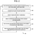
- FIG. 2 illustrates a flowchart according to a method of generating an output image signal based on the above described feedback loop according to an embodiment of the present invention.
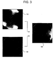
- FIG. 3 illustrates examples of beam intensity field according to an embodiment of the present invention
- FIG. 4 illustrates a schematic diagram of an x-ray system using spatial modulation of x-ray beam used in accordance with an embodiment of the present invention.
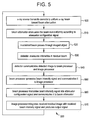
- FIG. 5 illustrates a flowchart according to a method of generating an output image signal based on the above described feedback loop using a beam-modulating filter in accordance with an embodiment of the present invention.
- FIGS. 6 and 7 illustrate an embodiment of the beam-modulating filter in accordance with an embodiment of the present invention.
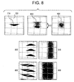
- FIG. 8 illustrates the effect of x-ray dodging according to an embodiment of the present invention.
- FIG. 9 illustrates an x-ray tube current waveform such as 920 may be used to smoothen motion blur produced by the harmonic oscillation such as 910 in accordance with an embodiment of the present invention.
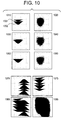
- FIG. 10 illustrates a more flexible way to adjust the local attenuation level with the use of inter-element occlusions according to an embodiment of the present invention.
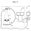
- FIG. 11 illustrates an add-on
beam modulation system 1100 that works in combination with a conventionalfluoroscopic imaging system 1105 used in accordance with an embodiment of the present invention. - FIG. 1 illustrates a schematic diagram on an
x-ray system 100 using x-ray beam modulation in accordance with an embodiment of the present invention.System 100 includes anx-ray source 105 producing a spatially modulatedbeam 110, an imagedobject 120, anx-ray detector 140, anx-ray beam processor 160, animage processor 170, and adisplay device 195.Modulated beam 110 passes through imagedobject 120, is attenuated to various degrees by its features, and formsresidual beam 130.Detector 140 measures the beam intensities in theresidual beam 130 and communicates aresidual image 150 to thebeam processor 160 and theimage processor 170. Abeam intensity signal 180 can be communicated from thebeam processor 160 to thex-ray source 105 and to theimage processor 170. The image processor produces a displayedimage signal 190 and communicates to displaydevice 195. - As mentioned above,
source 105 is capable of transmitting a spatially modulatedbeam 110 towards imagedobject 120. More specifically,source 105 may be capable of altering x-ray intensities acrossbeam 110 non-uniformly according to a beam intensity signal. A beam intensity signal is a digital representation of the intensity field of a spatially modulatedx-ray beam 110. -
Source 105 may be capable of altering the x-ray intensity field inbeam 110 by any one of several embodiments. For example,system 100 may use araster beam 110 by moving anarrow beam 110 back and forth in a raster pattern over particular areas ofobject 120 while varying the beam's intensity temporally and integrating the image in thedetector 140. In another embodiment,source 105 may include multiple beam sources, each exposing different portions of imagedobject 120.Source 105 may then modulatebeam 110 spatially by controlling the outputs of individual x-ray sources. - A spatially modulated
x-ray beam 110 may be constructed to match a distribution of radiographic thicknesses ofobject 120. For example, object 120 may have a known, measured, or anticipated distribution of thickness (for example, based on previous frames in a fluoroscopic sequence). Based at least on this distribution, a beam intensity signal may be created to increase the exposure to radiographically thick regions and/or decrease exposure to radiographically thin regions of imagedobject 120, thereby possibly resulting in the approximate equalization of intensities inresidual beam 130, for example.Residual beam 130 can include an x-ray beam after it has been attenuated by at least imagedobject 120, for example. - A spatially modulated
x-ray beam 110 may be constructed to match a distribution of region on interest inobject 120. Regions of interest may be areas or volumes inobject 120 that a user ofsystem 100 desires to image. Regions of interest inobject 120 may be known a priori from previous scans or general atlases, programmed, inferred, or anticipated. Based on at least the distribution of these regions of interest, a beam intensity signal may be created that results in increased x-ray exposures to regions of great interest and/or decrease x-ray exposures to regions of lesser interest, for example. - A spatially modulated
x-ray beam 110 may also be established to match a distribution of regions of sustained motion inobject 120.Object 120 may have regions or volumes that are likely to move relative toimaging system 100. Other regions are more likely to remain static. For example, ifobject 120 is a chest cavity of a human patient, it may include the patient's heart moving relative to the rest of the chest cavity. Regions of motion inobject 120 may be programmed by users, known a priori, measured, or anticipated. Less exposure is necessary in regions with little motion where image processing techniques may be employed to reuse information from earlier frames to produce a high-quality representation of these static regions. Based on at least the anticipated distribution of motion, a beam intensity signal may be created that results in increased x-ray exposures to regions with motion and/or decreased x-ray exposures to regions with little or no motion. - Finally, a spatially modulated
x-ray beam 110 may be established to match a combination of the three distributions described above, for example, (a) radiographic thicknesses, (b) regions of interests, and (c) regions of object motion may be combined to produce an improved beam intensity signal. - Once
beam 110 passes throughobject 120,detector 140 receivesresidual beam 130.Detector 140 is a device capable of measuring or recording the intensity pattern projected byresidual image 130. For example,detector 140 may be a solid-state x-ray detector, or an image intensifier coupled with a charged-coupled device digital video camera. - Based at least on measured intensities in
residual beam 130,detector 140 may createresidual image 150. For example,residual image 150 may comprise electronic data representing variousresidual beam 130 intensities received bydetector 140.Detector 140 communicatesresidual image 150 to at least one ofbeam processor 160 andimage processor 170. -
Beam processor 160 is an image-processing component ofsystem 100.Beam processor 160 may be any processor capable of receivingresidual image 150 fromdetector 140, creatingbeam intensity signal 180, and communicatingbeam intensity signal 180 to at least one ofsource 105 andimage processor 170.Beam processor 160 may be embodied in a computer general-purpose microprocessor, a software component, or a specialized digital signal processing ("DSP") circuit, for example.Beam processor 160 may be embedded in a system supplying processing forsystem 100, which may also perform additional tasks forsystem 100, such as those performed byimage processor 170. - After
beam processor 160 receivesresidual image 150,beam processor 150 examinesresidual image 150 to determine how thebeam intensity signal 180 needs to be modified. Thusbeam processor 160 completes a feedback loop that may periodically or continuously update thebeam 110 intensity field based at least on changes in imagedobject 120. Becausebeam processor 160 may "know" whatbeam 110 intensity field was applied to produce the receivedresidual image 130,beam processor 160 may not require a uniform-beam scout shot to estimate radiographic thicknesses in imagedobject 120 and may further be capable of periodically and/or continually updatingbeam intensity signal 180 as imagedobject 120 moves or changes throughout an imaging session. - When
beam intensity signal 180 is based primarily on radiographic thicknesses in imagedobject 120, the feedback loop may result inresidual image 130 being essentially uniform, within the beam-modulating performance limitations ofx-ray source 105. This is to say that in some cases, the spatial resolution limitations, the dynamic range limitations, or grayscale resolution limitations of the beam modulation inx-ray source 105 will not allow complete equalization of the beam, even though a significant improvement may be produced thanks to partial equalization. These limits include spatial resolution, intensity resolution, and dynamic range. The residual image can include information of object movement or other changes as well as detail that is not resolved by the beam modulator inx-ray source 105. If the beam modulation capabilities ofx-ray source 105 approach corresponding image acquisition capabilities ofx-ray detector 140, thenresidual image 140 may only include noise and motion, if any. Thus, considerable useful information about imaged object may be included inbeam intensity signal 180. - When
beam intensity signal 180 is also based on anticipated regions of motion and regions of interest inobject 120, thenbeam processor 160 may create abeam intensity signal 180 to cause increased beam intensity in these regions. Theresidual image 140 may therefore be non-uniform and may not accurately represent radiographic thicknesses in imagedobject 120. - As described above,
beam processor 160 may also communicatebeam intensity signal 180 toimage processor 170.Image processor 170 may be any processor capable of combining two or more image signals into a third image signal using image algebra operators. For example,image processor 170 may be a specialized hardware component, a programmable device, or an embedded software component running on a general-purpose microprocessor, for example. -
Image processor 170 subtractsbeam intensity signal 180 fromresidual image 150 to createoutput image 190. This subtraction may occur, for example, on a pixel-for-pixel basis. The specific meaning of the subtraction operation depends on the grayscale transforms applied to constituent images. For example, if a logarithmic grayscale transform has been applied to the residual image and to the beam intensity signal, then a simple arithmetic subtraction may be used.Combined image 190 may then accurately represent true radiographic thickness inobject 120, as if acquired with a uniform x-ray beam, for example. Signal delays may need to be built into the system to ensure that beam intensity signals 180 are combined with matchingresidual images 150. -
Image processor 170 may also adapt its processing in accordance to the same region-of-interest information and region-of-motion information used to produce thebeam intensity signal 180 inbeam processor 160. These adaptations may include spatial filtration, temporal filtration, feature enhancements, noise suppression, and others. For example, whenbeam processor 160 causes a dose reduction to a region of lesser interest,image processor 170 may increase noise reduction in corresponding image regions. As another example, whenbeam processor 160 causes a dose reduction to a region where little object motion is anticipated, then increased temporal filtration may be used to increase the reuse of previous frames to present a high-quality image. Multiscale image processing schemes may facilitate these solutions. - In another embodiment of the present invention, the present invention may be embodied as an external add-on device to an existing imaging system. In FIG. 11,
system 1100 includes an existingconventional system 1105, demarcated by a dash-lined box, which, in turn, includes anx-ray source 405 and anx-ray detector 140. An external beam-modulating device comprises an external add-onprocessor 1130, abeam modulator 1115, and adisplay device 1140. The conventional system'svideo output 1110 is connected to the add-onprocessor 1130. Thebeam modulator 1115 is attached to the conventional system's 1115x-ray source 405. The add-onprocessor 1130 plays the roles of thebeam processor 160 andimage processor 170 as in FIG. 4. Thebeam configuration signal 420 is conveyed to thebeam modulation 1115 along themodulator connection 1120. Thevideo signal 1110 conveys residual image signal to add-onprocessor 1130. - A conventional digital fluoroscopy x-ray imaging system typically includes
x-ray source 105,detector 140, and is capable of producing avideo output signal 1110. In operation,source 105 transmits anx-ray beam 110 towardsobject 120. Afterbeam 110 passes throughobject 120 and becomes residual beam 130 (as described above),detector 140 measures the x-ray intensities ofresidual beam 130. Thesystem 1105 then converts this residual beam into avideo signal 1110 which may be fed into other systems. - However, in this embodiment, external
beam modulation device 1115 may be added to such system to add the functionality of the present invention to an existing imaging system.Device 1115 is controlled by an add-onprocessor 1130. - In operation, processing block received
video output 1110 from theconventional system 1105. Add-onprocessor 1130 then acts to achieve the same functionality of thebeam processor 160 andimage processor 170, as described above. For example, once add-onprocessor 1130 receivesresidual image 1110, a beam processor similar tobeam processor 160 examines residualimage video signal 1120 to determine how a beam intensities inbeam 110 need to be modified. The beam processor of add-onprocessor 1130 completes a feedback loop that may periodically or continuously update thebeam 110 intensity field based at least on changes in imagedobject 120, as described above.Device 1120 may then communicate thebeam intensity signal 180 to beam modulator via thebeam modulator connection 1120. - In addition, once the beam processor of add-on
processor 1130 determines a beam intensity signal, add-onprocessor 1130 may also communicate the beam intensity signal to an internal image processor similar toimage processor 170 ofsystem 100. The image processor of add-on 1130 then subtractsbeam intensity signal 180 fromresidual image 150 to createoutput image 190. This subtraction may occur, for example, on a pixel-for-pixel basis.Device 1120 can then communicate theimage 190 to anexternal display device 1140 for display to a user ofsystem 1100. Therefore, the presently described embodiment provides for the simple addition of abeam modulation device 1120 to an existing x-ray imaging system in order to achieve the functionality of the present invention. - FIG. 2 illustrates a flowchart according to a
method 200 of generating anoutput image signal 190 based on the above described feedback loop according to an embodiment of the present invention. First, atstep 210, anx-ray source 105 transmits anx-ray beam 110 towards anobject 120. Next, atstep 220, the spatially modulatedbeam 110 passes through and is attenuated by theobject 120. The resultant beam that exists the other side of theobject 120 is aresidual beam 130. Atstep 230, adetector 140 measures x-ray intensities in theresidual beam 130 in order to create aresidual image 150. Next, atstep 240, thedetector 140 communicates theresidual image 150 to abeam processor 160 and animage processor 170. Next, atstep 250, thebeam processor 160 generates abeam intensity signal 180 and communicates signal 180 to thesource 105 andimage processor 170. Next, atstep 260, theimage processor 170 integrates theresidual image 150 with thebeam intensity signal 180 in order to produce animage output signal 190. Thisoutput signal 190 may then be displayed on adisplay device 195, for example. Next,method 200 may proceed back tostep 210. In this way,method 200 may proceed in a feedback loop manner. - The
beam processor 160 may create and communicatebeam intensity signal 180 on a regularly repeated or continuous basis such as fluoroscopic frame rates of 30, 15, or 7.5 frames per second. - In addition to combing the two constituents into the output image,
beam processor 170 may also perform other image processing tasks such as feature enhancement, dynamic range suppression, noise reduction, digital subtraction angiography ("DSA"), and grayscale transformations, for example. These processing tasks inimage processor 170 may be correlated with beam modulating tasks inbeam processor 160. For example, regions that are not anticipated to contain motion may receive reduced x-ray exposures, as controlled bybeam processor 160, but they may also be more heavily temporally averaged to reduce image noise inimage processor 170. As another example, regions of lesser interest may receive reduced x-ray exposures but may also be more spatially averaged to reduce noise inimage processor 170, for example. -
Display device 195 receivesoutput image 190 fromimage processor 170 and presents it to a viewer. - FIG. 3 illustrates examples of spatially modulated
beam 110 according to an embodiment of the present invention,residual image 150, and displayedimage signal 190 after the feedback loop has produced a near-optimal beam intensity field. In FIG. 3, the beam processor is programmed to equalize the residual image without consideration for regions of interest or anticipated object motion. In addition, the spatial resolution of the beam modulator is limited in FIG. 3, so the beam intensity signal comprises only the low-frequency image information and the residual image contains the remaining high-frequency image information. The combinedoutput image 190 appears as if acquired with a uniform-beam system at a high dose and high resolution, when, in fact, the averaged dose to the imaged object is significantly reduced. - FIG. 4 illustrates a schematic diagram of an
x-ray system 400 using spatial modulation ofx-ray beam 110 used in accordance with an embodiment of the present invention.System 400 includes anx-ray source 405 emitting an essentiallyuniform x-ray beam 410, a beam-modulatingfilter 415, an imagedobject 120, anx-ray detector 140, abeam processor 160, animage processor 170, and adisplay device 195. Theinitial beam 410 may not be completely uniform due to the Heel effect, for example.Beam modulating filter 415 is placed betweenx-ray source 405 and imagedobject 120. X-raysource 405 transmits an essentiallyuniform x-ray beam 410 toward modulatingfilter 415, imagedobject 120, anddetector 140. At least some portion ofuniform beam 410 passes through modulatingfilter 415 to form modulatedbeam 110.Modulated beam 110 passes through imagedobject 120, is attenuated to various degrees by its features, and formsresidual beam 130.X-ray detector 140 measures intensities inresidual beam 130, forms theresidual image 150 and communicates it tobeam processor 160 andimage processor 170. Thebeam processor 160 forms thebeam intensity signal 180 and communicates thesignal 180 to theimage processor 170. Thebeam processor 160 then translates thebeam intensity signal 180 into amodulator configuration signal 420 and communicates it to the beam-modulatingfilter 415. In this way, both thebeam intensity signal 180 and themodulator configuration signal 420 act to determine the spatial modulation of an x-ray beam. Theimage processor 170 createsoutput image 190 and communicates it to displaydevice 195.Image processor 170 may createoutput image 190 by integratingintensity signal 180 andmodulator configuration signal 420, similar to as described above in regards to FIG. 1. - Beam-modulating
filter 415 may attenuateinitial beam 410 according tomodulator configuration signal 420 to various degrees across the beam field. Beam-modulatingfilter 415 may be any device capable of selectively altering an amount attenuation ofinitial beam 410 to various degrees across the beam field, thereby creating spatially modulatedbeam 110. Similar to spatially modulatedbeam 110 in FIG. 1, beam-modulatingfilter 415 may attenuateinitial beam 410 as to create a desiredbeam 110 intensity field, as described above. - In an example, beam-modulating
filter 415's ability to selectively alter beam attenuations across the beam field may be compared to a liquid crystal display ("LCD") device. For example, an LCD device may control the passage of light through pixels by applying an electric current to a matrix of liquid crystals. By application of the proper current, individual pixels of the LCD may change to allow variable amounts of light through an LCD. Similarly, beam-modulatingfilter 415 may employ a matrix of pixels that, based on amodulator configuration signal 420 may change to allow various amounts ofx-ray beam 410 to pass, for example. - The functions of the remaining components of
system 400 are similar to those ofsystem 100 depicted in FIG. 1 and are described above. The functionality, applications, and benefits ofsystem 400 are similar to the functionality ofsystem 100 in FIG. 1. For example,sources object 120,detector 140,beam processor 160,image processor 170, anddisplay device 195 may behave similarly in both FIGS. 1 and 4. - FIG. 5 illustrates a flowchart according to a
method 500 of generating anoutput image signal 190 based on the above described feedback loop using a beam-modulating filter in accordance with an embodiment of the present invention. First, at step 505, anx-ray source 405 transmits anx-ray beam 410 towards a filter orbeam attenuator 415, as described above. Next, atstep 510, a beam attenuator (or filter) 415 attenuates thebeam 410, as described above. For example,attenuator 415 may attenuate thebeam 410 non-uniformly according to amodulator configuration signal 420. Oncebeam 410 has exited theattenuator 415,beam 410 becomes modulatedbeam 110, as described above.Modulated beam 110 then passes through an imagedobject 120 and becomes aresidual beam 130, as shown instep 520. Theresidual beam 130 then strikes adetector 140. Atstep 530 thedetector 140 measures the x-ray intensities of theresidual beam 130 in order to create aresidual image 150. Next, atstep 540, thedetector 140 communicates theresidual image 150 to abeam processor 160 and animage processor 170, as described above. Atstep 550, thebeam processor 160 generates abeam intensity signal 180 and communicates theintensity signal 180 to theimage processor 170. Next, atstep 560, thebeam processor 160 translates thebeam intensity signal 180 into aconfiguration signal 420, as described above, and communicates thesignal 420 to thebeam attenuator 415. Next, atstep 570, theimage processor 170 integrates theresidual image 150 with thebeam intensity signal 180 in order to produce anoutput image signal 190, as described above. Thisimage signal 190 may then be communicated to adisplay device 195 for display. Next,method 500 may proceed to step 505. In this way,method 500 may proceed in a feedback loop manner. - The basis for a practical embodiment of a beam-modulating filter in accordance with this invention is referred to as "x-ray dodging". The term originates from the dodging and burning techniques in darkroom light photography. To control the exposure to a portion of a photograph, photographers may introduce an opaque mask into the light beam for a calculated portion of the exposure time. To feather sharp mask edges in the photograph, photographers may wave the mask horizontally or vertically. The photographic paper integrates the exposure over time, so that the variations of total exposure to the photographic paper may be controlled across the image by the duration of time for which the region remains blocked by the mask.
- Beam-modulating filters previously disclosed (for example, as described above) modulate the beam by varying the thicknesses of the semi-transparent substances placed in the x-ray beam. In contrast, x-ray dodging uses radiographically opaque elements to block the beam completely but only for a controlled portion of a frame integration period. This strategy endows the beam modulator with flexibility, a high number of gradation levels, high spatial resolution, and a high dynamic range. In addition, unlike the previous attempted solutions (as described above), beam modulation using x-ray dodging is not as sensitive to x-ray photon energies as long as the x-ray blocking elements remain radiographically opaque. In the range of x-ray techniques used for interventional medical fluoroscopy and diagnostic radiography, elements made of 0.8-1.5 mm of tungsten may be sufficient to effectively block the x-ray beam.
- To control the exposure times, the x-ray-blocking elements may be moved, rotated, and/or oscillated at high speeds or frequencies with high precision. To help reduce the complexity of the motion, the intensity of the uniform beam may be varied synchronized with the motion of the x-ray blocking elements. In practice, it may be easier to make these motions and beam intensity variations periodic in time. Therefore, the x-ray dodging technique may be defined as the use of controlled arrangements of x-ray blocking elements in the x-ray beam undergoing a high-frequency periodic motion synchronized with periodic temporal x-ray beam modulations and detector frame integration periods to produce desired spatial modulation of the x-ray beam.
- FIG. 8 illustrates the effect of x-ray dodging according to an embodiment of the present invention. In this embodiment exposed
area 615 is divided intoimage cells 720. A radiographicallyopaque element 710 may be introduced into any image cell. When theelement 710 undergoes anoscillatory motion 810 at a high frequency in a plane perpendicular to the x-ray beam with the amplitude of about one cell width, a semitransparentblurred attenuation pattern 800 may be produced. Here theoscillation 810 is assumed to be harmonic or sinusoidal. Theoscillatory motion 810 may not completely remove sharp features from theattenuation pattern 800. These sharp features may introduce artifacts in anoutput image 190. To remove these sharp features, the system may vary the intensity of theinitial uniform beam 410 synchronized with the phase of theoscillatory motion 810. - For example, let φ k (θ,ρ)∈[0,1] be the attenuation function of the k th basis disc defined in polar coordinates θ,ρ such that the center of
disc rotation 630 is at ρ=0. The system will then shift thephases 640 of each disc k by appropriate angular offsets ψk to produce a desired combined attenuation function of the entire stack
Indicators 640 representing one or more phase shifts are included in FIG. 6 for demonstration purposes only. Theentire disc stack 610 is caused to undergo rotational oscillation so that its angular offset ε varies as


uniform x-ray beam 410, one can effectively convolve the attenuation pattern Φ(θ,ρ) with an arbitrary function g(θ) along the θ axis. For example, one may choose g(θ) to be a smoothing band-limiting kernel such as a Gaussian or Hanning kernels. Then h(θ)= g(θ) and beam intensity waveform may be computed as
- FIG. 9 illustrates an example of an oscillation offset
function 910 that may correspond to the harmonic oscillation function ε(t) described above and the x-ray tube current waveform 920 (mA) that produces proportionaluniform beam 410 intensity I 0 (t) as described above. Thex-ray tube waveform 920 causes the smoothing kernel h(θ) to become a Gaussian kernel, resulting in a smoothing effect such as illustrated in FIG. 8. - Notice that the motion blurring in FIG. 8 smoothens the attenuation pattern along the direction of
oscillation 810 only. The smoothness along the radial axis is achieved due to smooth variations of the widths of thex-ray blocking elements 710. When a column ofx-ray blocking elements 830 is smoothened byoscillations 810 synchronized withbeam intensity modulation 920 of FIG. 9, the resultingbeam modulation pattern 840 may be made completely uniform along the direction ofoscillation 810 due at least in part to the band-limited convolution kernel h(x). Rows ofbeam blocking elements 850 may result in uniform attenuation orthogonal tooscillation 810 due at least in part to the band-limited width variations of thex-ray blocking elements 710. In this way, thex-ray block elements 710 combined withperiodic motion 810 and temporal beam intensity modulation may be used to produce smoothly varying attenuation patterns. These patterns may be critical to avoid image artifacts or the necessity for perfect beam alignment. - Motion blur and temporal beam modulation remove sharp features from the attenuation pattern. The area blocked by a beam-blocking
element 710 will contribute to the attenuation produced in the image cell in which it is placed. The system may regulate the local attenuation by selecting from a set of possible beam-blocking elements of various widths. FIG. 10 illustrates a more flexible way to adjust the local attenuation level with the use of inter-element occlusions according to an embodiment of the present invention. Two beam-blockingelements Elements elements - For example, when the two
elements element arrangement 1010, the resultingattenuation cell 1020 may be darker than when theelements element arrangements corresponding attenuation cells 1040 and 1060). In addition, other ways of changing the projected area of a beam-blocking element may be used such as rotation of the element or moving the element closer to or away from the focal spot. - The design of x-ray-blocking elements may also take into consideration how adjacent cells interact. For example, it may be desirable to have the capability to block a portion of the x-ray beam completely. In order to do so, rows and/or columns of elements may mesh tightly so that the x-ray beam is blocked completely. Beam-blocking elements are designed to interlock with elements from adjacent rows as to be configurable to block an entire area without gaps. For example, two adjacent columns of
cells arrangement 1080. After they are blurred by motion, the smoothenedattenuation pattern 1085 contains areas where the beam is completely blocked. - Inter-element occlusions are just one of several possible approaches of blocking varying portions of the x-ray beam with one or several beam-blocking elements. For example, rotating or rolling the elements or moving them toward or away from the x-ray source may be employed. Neither do inter-element occlusions need to be limited to two elements. Multiple elements occluding one another in various arrangements may provide even greater flexibility in creating desired attenuation patterns.
- FIG. 6 and FIG. 7 each illustrate an embodiment of the beam-modulating
filter 415 in accordance with an embodiment of the present invention. Thex-ray source 105 produces an essentiallyuniform x-ray beam 410, as described above. Theuniform x-ray beam 410 traverses a stack of disc-shaped basis filters 620. The basis filters 620 are made of a radiographically translucent material and contain arrangements of x-ray-blockingelements 710. - The relative
angular offsets 640 of the basis discs place different portions of each disc in the exposedarea 615. For example, angular offset 640 of a given disc may be determined by an angular offset 640 of a particularx-ray blocking element 710 or other known position marker indicated by reference 635. The discs' angular offsets may be controlled independently. By varying the number ofdiscs 620, the various arrangements ofelements 710, and the various angular displacements of thevarious discs 620, a large number of possible arrangements of x-ray blocking elements in the exposedarea 615 are possible. - The entire disc stack may be caused to undergo a high-frequency rotational oscillation around the
axis 630 synchronized with the periodic temporal modulation of theuniform beam 410. - The rotational offsets of the basis discs may be controlled by the
modulator configuration signal 420 originating from thebeam processor 160, as described above. The motors and mechanics driving these offsets are not shown in FIG. 6, but may be embodied, for example, in a stepper motor configuration known to those of ordinary skill in the art. - In an example of an embodiment of the present invention, the circular exposed
area 615 of abasis filter 620 may be divided into columns and rows ofcells 720, as shown in FIG. 7. For example, in FIG. 7, the exposedcircular area 615 is divided into five 7-cell central columns and two 3-cell boundary columns. The beam attenuation level of each of the 41 cells can be controlled independently with smooth transitions between them. - Two basis discs are assigned to each of the five central columns of image cells (ten basis discs total). Each
disc 620 may be rotated to such a position that eachcell 720 in the exposed column will either include an x-ray-blocking element or not contain one. For a seven-cell column, 27=128 such septuplets are possible. If 1 represents the presence of an x-ray-blocking element and 0 represents the absence of an x-ray-blocking element, then arranging the elements circularly around a basis disc according to the 128-element pattern 00001110000110111110110010011111110011000 10101011110001100111010110110101001101000 10010001111010010111011100101000010110000 0 1 0 0 can allow rotating thedisc 620 to a position producing any possible such septuplet. Since two discs may be assigned to each column, for each of the 35 central cells, four possible configurations are possible: (1) no x-ray block elements present, (2) one x-ray blocking element from first basis disc present, (3) one x-ray-blocking element from second basis disc present, and (4) two x-ray-blocking elements present, one from the first and one from the second basis disc. For example, if the resulting cell attenuation from an element from the first disc is 0.33 and from the second disc - 0.67, then when both elements are present in the cell, the attenuation may be varied in continuous gradation from 0.67 to 1.0 by adjusting the degree of the inter-element occlusions. - Many other pattern designs are possible, not necessarily based on cell matrices. For example, in a circular exposed area such as 615 in FIG. 7, the vertical boundary columns contain only three cells. Instead of using two discs with a binary pattern of beam-blocking elements such 715 as described above to provide four independent attenuation levels, a quinternary attenuation pattern may be used to provide any of five attenuation patterns in each cell, independently. An example of such 125-cell circular pattern is 0 0 1 1 1 2 2 2 33344411330022442200331144332211004401234 02301341240343423231212024241313030201014 1 4 2 0 3 1 4 0 4 1 0 2 1 3 2 4 3 0 4 2 1 4 3 1 0 3 2 0 4 3 2 1 0 4 0. In this pattern any contiguous triplet of
digits 0 through 4 may be found. If five types of beam blocking elements corresponding to these digits are arranged in a circle on a disc, then any combination of such elements may be selected into the three exposed cells.
Claims (10)
- An x-ray imaging system using spatial modulation of an x-ray beam, said system including:an x-ray source (105, 405) transmitting said beam (110) towards an object (120) to be imaged, said beam (110) containing a plurality of x-ray intensities varying spatially and temporally and based on at least a beam intensity signal (180);an x-ray detector (140) receiving said beam (130) after an interaction between said beam (110) and said object (120), said detector (140) measuring a plurality of residual intensities of said beam and producing a residual image signal (150) based on at least said residual intensities;a beam processor (160) creating said beam intensity signal (180) based on at least one of a previous beam intensity signal (180), said residual intensities, a region of interest in said object (120) and anticipated object motion; andan image processor (170) producing an output image signal (190), said output image signal (190) based on one or more of said residual image signal (150) and said beam intensity signal (180).
- The system of claim 1, wherein said plurality of x-ray intensities is dynamically altered.
- The system of claim 1, wherein said plurality of x-ray intensities is altered to match one or more of a distribution of anticipated radiographic thicknesses in said imaged object (120), a distribution of said regions of interest in said imaged object (120), and a distribution of regions of motion in said imaged object (120).
- A method for x-ray imaging with spatial modulation of an x-ray beam, said method including:transmitting said beam towards an object (120) to be imaged, an x-ray intensity field of said beam (120) varying across said beam(120), said intensity field based on at least a beam intensity signal (180);receiving said beam at an x-ray detector (140);measuring a plurality of intensities of said beam (110) at said detector (140);creating a residual image signal (150) based on at least said intensities measured at said detector (140); andproducing an output image signal (190), said output image signal (190) based on one or more of said residual image signal (150) and said beam intensity signal (180),wherein said beam intensity signal (180) is based on one or more of a predicted information density and said intensities measured at said detector (140).
- The method of claim 4, further including dynamically altering said beam intensity field.
- The method of claim 4, wherein said beam intensity field includes one or more of a distribution of radiographic thicknesses in imaged object (120), a distribution of regions of interest, and a distribution of regions of anticipated object (120) motion.
- A system for creating an x-ray image using spatial modulation of an x-ray beam, said system including:an x-ray source (105, 405) producing said beam (110), said beam (110) including a field of continually varying x-ray intensities;an object (120) to be imaged including at least one predicted information density, said predicted information density including at least one of a radiographic thickness, a region of interest, and a region of object (120) motion;a detector (140) creating a residual image (150) based on at least x-ray intensities of said beam (110) received at said detector (140) and attenuated by one or more of said object (120) and said predicted information density; anda beam processing unit (160) examining said residual image (150) in order to determine at least one modification to said field of continually varying x-ray intensities transmitted in at least one subsequent beam (110) transmitted by said source (105, 405).
- The system of claim 7, wherein said beam processing unit (160) communicates said modification to said field of continually varying x-ray intensities to one or more of said source (105, 405) and a filter (415) disposed between said source (105, 405) and said object (120).
- The system of claim 7, wherein said beam processing unit (160) continually modifies said field of continually varying x-ray intensities in subsequent beams (110) transmitted by said source (105, 405).
- The system of claim 9, wherein said beam processing unit (160) and an image processing unit (170) are included in an external beam modification device (1130) to augment a conventional system (1100) with dynamic beam modulating capabilities.
Applications Claiming Priority (1)
| Application Number | Priority Date | Filing Date | Title |
|---|---|---|---|
| US10/945,649 US7272208B2 (en) | 2004-09-21 | 2004-09-21 | System and method for an adaptive morphology x-ray beam in an x-ray system |
Publications (2)
| Publication Number | Publication Date |
|---|---|
| EP1642529A1 true EP1642529A1 (en) | 2006-04-05 |
| EP1642529B1 EP1642529B1 (en) | 2011-02-23 |
Family
ID=35509327
Family Applications (1)
| Application Number | Title | Priority Date | Filing Date |
|---|---|---|---|
| EP05255494A Expired - Fee Related EP1642529B1 (en) | 2004-09-21 | 2005-09-08 | System and method for intensity modulated x-ray imaging |
Country Status (8)
| Country | Link |
|---|---|
| US (1) | US7272208B2 (en) |
| EP (1) | EP1642529B1 (en) |
| JP (1) | JP5468720B2 (en) |
| KR (1) | KR101148299B1 (en) |
| CN (1) | CN1766591B (en) |
| CA (1) | CA2518532A1 (en) |
| DE (1) | DE602005026486D1 (en) |
| MX (1) | MXPA05010120A (en) |
Cited By (6)
| Publication number | Priority date | Publication date | Assignee | Title |
|---|---|---|---|---|
| DE102006037969A1 (en) * | 2006-08-14 | 2008-02-28 | Siemens Ag | Method for x-ray imaging under application of subtraction technology, involves recording x-ray image of examination area by detector dose, where multiple other x-ray images of examination area are recorded by another detector dose |
| EP1990006A1 (en) * | 2007-05-08 | 2008-11-12 | Canon Kabushiki Kaisha | Radiographic imaging control apparatus and method for controlling the same |
| WO2013132387A3 (en) * | 2012-03-03 | 2013-12-05 | Controlrad Systems, Inc. | X-ray reduction system |
| EP3373045A1 (en) * | 2010-02-03 | 2018-09-12 | Rapiscan Systems, Inc. | Scanning systems |
| US10754057B2 (en) | 2016-07-14 | 2020-08-25 | Rapiscan Systems, Inc. | Systems and methods for improving penetration of radiographic scanners |
| US11119245B2 (en) | 2012-02-08 | 2021-09-14 | Rapiscan Systems, Inc. | High-speed security inspection system |
Families Citing this family (42)
| Publication number | Priority date | Publication date | Assignee | Title |
|---|---|---|---|---|
| US7963695B2 (en) | 2002-07-23 | 2011-06-21 | Rapiscan Systems, Inc. | Rotatable boom cargo scanning system |
| US8275091B2 (en) | 2002-07-23 | 2012-09-25 | Rapiscan Systems, Inc. | Compact mobile cargo scanning system |
| US6928141B2 (en) | 2003-06-20 | 2005-08-09 | Rapiscan, Inc. | Relocatable X-ray imaging system and method for inspecting commercial vehicles and cargo containers |
| WO2005092195A1 (en) * | 2004-03-29 | 2005-10-06 | National Institute Of Radiological Sciences | Heel effect correction filter, x-ray irradiator, x-ray ct apparatus, and x-ray ct imaging method |
| US7471764B2 (en) | 2005-04-15 | 2008-12-30 | Rapiscan Security Products, Inc. | X-ray imaging system having improved weather resistance |
| DE102005034912B4 (en) * | 2005-07-26 | 2007-10-04 | Siemens Ag | Particle therapy system, method for determining control parameters of such a therapy system, radiotherapy planning device and irradiation method |
| US7330535B2 (en) * | 2005-11-10 | 2008-02-12 | General Electric Company | X-ray flux management device |
| US7526064B2 (en) | 2006-05-05 | 2009-04-28 | Rapiscan Security Products, Inc. | Multiple pass cargo inspection system |
| US7664227B2 (en) * | 2006-05-25 | 2010-02-16 | Ucl Business Plc | Intelligent adaptive x-ray imaging system |
| US7400703B2 (en) * | 2006-08-11 | 2008-07-15 | General Electric Company | Method and system for controlling radiation intensity of an imaging system |
| CN100510725C (en) * | 2006-11-14 | 2009-07-08 | 北京国药恒瑞美联信息技术有限公司 | Virtual grid imaging method and system used for eliminating influence of scattered radiation |
| DE102007019334A1 (en) * | 2007-04-24 | 2008-11-06 | Siemens Ag | Aperture device for an x-ray device provided for scanning an object, x-ray device for scanning an object and method for generating image information of an object by means of an x-ray device |
| WO2009105645A1 (en) * | 2008-02-20 | 2009-08-27 | Imaging Sciences International Llc | Tomographic imaging motion scan quality rating |
| GB0809110D0 (en) | 2008-05-20 | 2008-06-25 | Rapiscan Security Products Inc | Gantry scanner systems |
| JP6000549B2 (en) * | 2008-08-11 | 2016-09-28 | ラピスカン ラボラトリーズ、インコーポレイテッド | System and method using intensity modulated X-ray source |
| US8194821B2 (en) * | 2008-09-26 | 2012-06-05 | Varian Medical Systems, Inc. | Methods, systems, and computer-program products to correct degradation in tomographic images caused by extraneous radiation |
| JP4847568B2 (en) * | 2008-10-24 | 2011-12-28 | キヤノン株式会社 | X-ray imaging apparatus and X-ray imaging method |
| KR100998875B1 (en) | 2008-10-29 | 2010-12-08 | 제일모직주식회사 | Weatherable Thermoplastic Resin Having Excellent Low Gloss Characteristic and Method of Preparing the Same |
| EP2341090B1 (en) | 2009-12-31 | 2012-09-12 | Cheil Industries Inc. | Weatherable thermoplastic resin having excellent low gloss characteristic and method of preparing the same |
| GB201001738D0 (en) | 2010-02-03 | 2010-03-24 | Rapiscan Lab Inc | Scanning systems |
| CN103415253B (en) * | 2010-12-09 | 2015-11-25 | 皇家飞利浦电子股份有限公司 | For the Post-patient dynamic filter of computer tomography (CT) |
| US8699000B2 (en) | 2010-12-23 | 2014-04-15 | Asml Netherlands B.V. | Illumination system for a lithographic apparatus |
| KR20120076301A (en) | 2010-12-29 | 2012-07-09 | 제일모직주식회사 | Low gloss thermoplastic resin composition having good heat and weather resistance |
| US10079003B2 (en) * | 2011-06-02 | 2018-09-18 | The Research Foundation For The State University Of New York | Method and device for imaging a region of interest |
| US9218933B2 (en) | 2011-06-09 | 2015-12-22 | Rapidscan Systems, Inc. | Low-dose radiographic imaging system |
| US9224573B2 (en) | 2011-06-09 | 2015-12-29 | Rapiscan Systems, Inc. | System and method for X-ray source weight reduction |
| KR101469263B1 (en) | 2011-12-22 | 2014-12-05 | 제일모직주식회사 | Thermoplastic resin composition and articles thereof |
| DE102012201856B4 (en) | 2012-02-08 | 2015-04-02 | Siemens Aktiengesellschaft | Contour collimator and adaptive filter with electroactive polymer elements and associated method |
| DE102012220750B4 (en) * | 2012-02-08 | 2015-06-03 | Siemens Aktiengesellschaft | Contour collimator with a magnetic, X-ray absorbing liquid and associated method |
| US10056164B2 (en) * | 2012-12-03 | 2018-08-21 | Koninklijke Philips N.V. | Translating x-ray beam transmission profile shaper |
| KR20140087246A (en) | 2012-12-28 | 2014-07-09 | 삼성전자주식회사 | X-ray image apparatus and control method for the same |
| CA2894235A1 (en) | 2013-01-04 | 2014-07-10 | American Science And Engineering, Inc. | Dynamic dose reduction in x-ray inspection |
| KR102167245B1 (en) | 2013-01-31 | 2020-10-19 | 라피스캔 시스템스, 인코포레이티드 | Portable security inspection system |
| US9431141B1 (en) * | 2013-04-30 | 2016-08-30 | The United States Of America As Represented By The Secretary Of The Air Force | Reconfigurable liquid attenuated collimator |
| KR101450804B1 (en) * | 2013-11-20 | 2014-10-15 | 서강대학교산학협력단 | Image guiding instrumentation using radiation detector for surgery |
| DE102015226489A1 (en) * | 2015-12-22 | 2017-06-22 | Siemens Healthcare Gmbh | X-ray system and method for image reconstruction |
| DE102016205176A1 (en) * | 2016-03-30 | 2017-10-05 | Siemens Healthcare Gmbh | Apparatus and method for creating an X-ray panoramic image |
| US10342505B2 (en) * | 2016-03-31 | 2019-07-09 | General Electric Company | System and method for adjusting a radiation dose during imaging of an object within a subject |
| CN106772549B (en) * | 2017-01-06 | 2023-07-25 | 中国工程物理研究院核物理与化学研究所 | Point-like radioactive source irradiator |
| CN109444181B (en) * | 2018-10-30 | 2024-02-06 | 云南昆船设计研究院有限公司 | Method for balancing X-ray detection area ray field intensity and balancing plate |
| CN111759335B (en) * | 2020-05-29 | 2023-05-02 | 东软医疗系统股份有限公司 | Acquisition method and device of multi-energy spectrum imaging data, electronic equipment and storage medium |
| CN111695529B (en) * | 2020-06-15 | 2023-04-25 | 北京师范大学 | X-ray source detection method based on human skeleton key point detection algorithm |
Citations (3)
| Publication number | Priority date | Publication date | Assignee | Title |
|---|---|---|---|---|
| WO1998027867A1 (en) * | 1996-12-20 | 1998-07-02 | Sven Ploem | Electromagnetic radiation imaging device with controlled diaphragm means |
| US6055295A (en) * | 1998-01-29 | 2000-04-25 | Siemens Corporate Research, Inc. | Method and apparatus for automatic collimation in x-ray peripheral imaging |
| US6480570B1 (en) * | 1994-03-11 | 2002-11-12 | Hitachi Medical Corporation | X-ray image display apparatus |
Family Cites Families (22)
| Publication number | Priority date | Publication date | Assignee | Title |
|---|---|---|---|---|
| SE347859B (en) * | 1970-11-30 | 1972-08-14 | Medinova Ab | |
| US4347440A (en) * | 1980-07-09 | 1982-08-31 | Siemens Medical Laboratories, Inc. | Filter arrangement for an x-ray apparatus |
| US4497062A (en) * | 1983-06-06 | 1985-01-29 | Wisconsin Alumni Research Foundation | Digitally controlled X-ray beam attenuation method and apparatus |
| US5081659A (en) * | 1987-10-30 | 1992-01-14 | Duke University | Variable compensation method and apparatus for radiological images |
| US4868857A (en) * | 1987-10-30 | 1989-09-19 | Duke University | Variable compensation method and apparatus for radiological images |
| FR2654917A1 (en) * | 1989-11-24 | 1991-05-31 | Gen Electric Cgr | RADIOLOGY APPARATUS WITH HOMOGENIZATION FILTER. |
| US5107529A (en) * | 1990-10-03 | 1992-04-21 | Thomas Jefferson University | Radiographic equalization apparatus and method |
| JPH05192319A (en) * | 1991-11-15 | 1993-08-03 | Toshiba Corp | X-ray diagnostic device |
| US5237598A (en) * | 1992-04-24 | 1993-08-17 | Albert Richard D | Multiple image scanning X-ray method and apparatus |
| US5267296A (en) * | 1992-10-13 | 1993-11-30 | Digiray Corporation | Method and apparatus for digital control of scanning X-ray imaging systems |
| EP0740839B1 (en) * | 1994-10-25 | 1998-09-23 | Koninklijke Philips Electronics N.V. | X-ray apparatus comprising a filter |
| JPH0910191A (en) * | 1995-06-26 | 1997-01-14 | Shimadzu Corp | Radiation camera apparatus |
| US5778046A (en) * | 1996-01-19 | 1998-07-07 | The Regents Of The University Of California | Automatic X-ray Beam Equalizer |
| US5881127A (en) * | 1996-01-19 | 1999-03-09 | The Regents Of The University Of California | Automatic x-ray beam equalizer |
| US5878111A (en) * | 1996-09-20 | 1999-03-02 | Siemens Aktiengesellschaft | X-ray absorption filter having a field generating matrix and field sensitive liquids |
| US6201852B1 (en) * | 1997-04-11 | 2001-03-13 | University Of Medicine & Denistry Of New Jersey | Method and means for variably attenuating radiation |
| US6108403A (en) * | 1998-04-21 | 2000-08-22 | Picker International, Inc. | X-ray equalization filter |
| DE19950794A1 (en) * | 1999-10-21 | 2001-06-13 | Siemens Ag | Radiological device e.g. for radiological imaging for computer tomography |
| WO2001043145A1 (en) * | 1999-12-08 | 2001-06-14 | Koninklijke Philips Electronics N.V. | X-ray apparatus with filter comprising filter elements with adjustable x-ray absorption and x-ray absorption sensor |
| JP4776798B2 (en) * | 2000-03-29 | 2011-09-21 | 東芝医用システムエンジニアリング株式会社 | X-ray diagnostic equipment |
| DE10039002A1 (en) * | 2000-08-10 | 2002-02-21 | Philips Corp Intellectual Pty | Image correction method for an X-ray detector |
| JP2004008490A (en) * | 2002-06-07 | 2004-01-15 | Toshiba Medical System Co Ltd | X-ray image diagnostic apparatus |
-
2004
- 2004-09-21 US US10/945,649 patent/US7272208B2/en active Active
-
2005
- 2005-09-08 EP EP05255494A patent/EP1642529B1/en not_active Expired - Fee Related
- 2005-09-08 CA CA002518532A patent/CA2518532A1/en not_active Abandoned
- 2005-09-08 DE DE602005026486T patent/DE602005026486D1/en active Active
- 2005-09-15 JP JP2005267956A patent/JP5468720B2/en not_active Expired - Fee Related
- 2005-09-20 KR KR1020050087319A patent/KR101148299B1/en active IP Right Grant
- 2005-09-21 MX MXPA05010120A patent/MXPA05010120A/en active IP Right Grant
- 2005-09-21 CN CN2005101089526A patent/CN1766591B/en not_active Expired - Fee Related
Patent Citations (3)
| Publication number | Priority date | Publication date | Assignee | Title |
|---|---|---|---|---|
| US6480570B1 (en) * | 1994-03-11 | 2002-11-12 | Hitachi Medical Corporation | X-ray image display apparatus |
| WO1998027867A1 (en) * | 1996-12-20 | 1998-07-02 | Sven Ploem | Electromagnetic radiation imaging device with controlled diaphragm means |
| US6055295A (en) * | 1998-01-29 | 2000-04-25 | Siemens Corporate Research, Inc. | Method and apparatus for automatic collimation in x-ray peripheral imaging |
Cited By (9)
| Publication number | Priority date | Publication date | Assignee | Title |
|---|---|---|---|---|
| DE102006037969A1 (en) * | 2006-08-14 | 2008-02-28 | Siemens Ag | Method for x-ray imaging under application of subtraction technology, involves recording x-ray image of examination area by detector dose, where multiple other x-ray images of examination area are recorded by another detector dose |
| EP1990006A1 (en) * | 2007-05-08 | 2008-11-12 | Canon Kabushiki Kaisha | Radiographic imaging control apparatus and method for controlling the same |
| EP3373045A1 (en) * | 2010-02-03 | 2018-09-12 | Rapiscan Systems, Inc. | Scanning systems |
| US11119245B2 (en) | 2012-02-08 | 2021-09-14 | Rapiscan Systems, Inc. | High-speed security inspection system |
| US11561321B2 (en) | 2012-02-08 | 2023-01-24 | Rapiscan Systems, Inc. | High-speed security inspection system |
| US11852775B2 (en) | 2012-02-08 | 2023-12-26 | Rapiscan Systems, Inc. | High-speed security inspection system |
| WO2013132387A3 (en) * | 2012-03-03 | 2013-12-05 | Controlrad Systems, Inc. | X-ray reduction system |
| US10754057B2 (en) | 2016-07-14 | 2020-08-25 | Rapiscan Systems, Inc. | Systems and methods for improving penetration of radiographic scanners |
| US11397276B2 (en) | 2016-07-14 | 2022-07-26 | Rapiscan Systems, Inc. | Systems and methods for improving penetration of radiographic scanners |
Also Published As
| Publication number | Publication date |
|---|---|
| CN1766591B (en) | 2011-02-09 |
| EP1642529B1 (en) | 2011-02-23 |
| US7272208B2 (en) | 2007-09-18 |
| KR101148299B1 (en) | 2012-05-21 |
| MXPA05010120A (en) | 2006-04-27 |
| CA2518532A1 (en) | 2006-03-21 |
| US20060062353A1 (en) | 2006-03-23 |
| KR20060051425A (en) | 2006-05-19 |
| CN1766591A (en) | 2006-05-03 |
| DE602005026486D1 (en) | 2011-04-07 |
| JP5468720B2 (en) | 2014-04-09 |
| JP2006087920A (en) | 2006-04-06 |
Similar Documents
| Publication | Publication Date | Title |
|---|---|---|
| EP1642529B1 (en) | System and method for intensity modulated x-ray imaging | |
| US4773087A (en) | Quality of shadowgraphic x-ray images | |
| US7400703B2 (en) | Method and system for controlling radiation intensity of an imaging system | |
| US5107529A (en) | Radiographic equalization apparatus and method | |
| CA1214285A (en) | Digitally controlled x-ray beam attenuation method and apparatus | |
| JP6125656B2 (en) | X-ray reduction system | |
| US4868857A (en) | Variable compensation method and apparatus for radiological images | |
| Rudin et al. | Region of interest fluoroscopy | |
| EP3993706B1 (en) | Narrow beam ct using a 3d fluence modulation and scatter shield system | |
| EP1444952B1 (en) | Scanning digital radiography system with reduced ionizing-radiation dose | |
| US6385287B1 (en) | Method and system for providing virtual grid for portal imaging in a radiotherapy system | |
| Labbe et al. | The x‐ray fovea, a device for reducing x‐ray dose in fluoroscopy | |
| US5081659A (en) | Variable compensation method and apparatus for radiological images | |
| US5008914A (en) | Quantitative imaging employing scanning equalization radiography | |
| Ritenour | Physics overview of screen-film radiography. | |
| JP2000083946A (en) | Method and device for correction projection and radiation tomography apparatus | |
| Sassi et al. | Moving segments region of interest attenuator for x‐ray fluoroscopy | |
| Boone et al. | Filter wheel equalization in DSA: simulation results | |
| Yatsenko et al. | Regional exposure management with spatial x-ray gating | |
| Robert et al. | A filtering method for signal equalization in region‐of‐interest fluoroscopy | |
| Huck | Development and validation of two novel x-ray filters in computed tomography with focus on fluence modulation for region-of-interest imaging | |
| Droege et al. | The significance of screen resolution in treatment verification | |
| Skull et al. | Radiographic Imaging | |
| JP2001037746A (en) | Medical radiation light x-ray image pickup device | |
| Suwa et al. | X-ray K-edge subtraction television system |
Legal Events
| Date | Code | Title | Description |
|---|---|---|---|
| PUAI | Public reference made under article 153(3) epc to a published international application that has entered the european phase |
Free format text: ORIGINAL CODE: 0009012 |
|
| AK | Designated contracting states |
Kind code of ref document: A1 Designated state(s): AT BE BG CH CY CZ DE DK EE ES FI FR GB GR HU IE IS IT LI LT LU LV MC NL PL PT RO SE SI SK TR |
|
| AX | Request for extension of the european patent |
Extension state: AL BA HR MK YU |
|
| 17P | Request for examination filed |
Effective date: 20061005 |
|
| 17Q | First examination report despatched |
Effective date: 20061103 |
|
| AKX | Designation fees paid |
Designated state(s): DE FR GB HU IT |
|
| GRAP | Despatch of communication of intention to grant a patent |
Free format text: ORIGINAL CODE: EPIDOSNIGR1 |
|
| GRAS | Grant fee paid |
Free format text: ORIGINAL CODE: EPIDOSNIGR3 |
|
| GRAA | (expected) grant |
Free format text: ORIGINAL CODE: 0009210 |
|
| AK | Designated contracting states |
Kind code of ref document: B1 Designated state(s): DE FR GB HU IT |
|
| REG | Reference to a national code |
Ref country code: GB Ref legal event code: FG4D |
|
| REF | Corresponds to: |
Ref document number: 602005026486 Country of ref document: DE Date of ref document: 20110407 Kind code of ref document: P |
|
| REG | Reference to a national code |
Ref country code: DE Ref legal event code: R096 Ref document number: 602005026486 Country of ref document: DE Effective date: 20110407 |
|
| PLBE | No opposition filed within time limit |
Free format text: ORIGINAL CODE: 0009261 |
|
| STAA | Information on the status of an ep patent application or granted ep patent |
Free format text: STATUS: NO OPPOSITION FILED WITHIN TIME LIMIT |
|
| 26N | No opposition filed |
Effective date: 20111124 |
|
| REG | Reference to a national code |
Ref country code: DE Ref legal event code: R097 Ref document number: 602005026486 Country of ref document: DE Effective date: 20111124 |
|
| GBPC | Gb: european patent ceased through non-payment of renewal fee |
Effective date: 20110908 |
|
| PG25 | Lapsed in a contracting state [announced via postgrant information from national office to epo] |
Ref country code: IT Free format text: LAPSE BECAUSE OF FAILURE TO SUBMIT A TRANSLATION OF THE DESCRIPTION OR TO PAY THE FEE WITHIN THE PRESCRIBED TIME-LIMIT Effective date: 20110223 |
|
| PG25 | Lapsed in a contracting state [announced via postgrant information from national office to epo] |
Ref country code: GB Free format text: LAPSE BECAUSE OF NON-PAYMENT OF DUE FEES Effective date: 20110908 |
|
| PG25 | Lapsed in a contracting state [announced via postgrant information from national office to epo] |
Ref country code: HU Free format text: LAPSE BECAUSE OF FAILURE TO SUBMIT A TRANSLATION OF THE DESCRIPTION OR TO PAY THE FEE WITHIN THE PRESCRIBED TIME-LIMIT Effective date: 20110223 |
|
| PGFP | Annual fee paid to national office [announced via postgrant information from national office to epo] |
Ref country code: FR Payment date: 20130919 Year of fee payment: 9 |
|
| REG | Reference to a national code |
Ref country code: FR Ref legal event code: ST Effective date: 20150529 |
|
| PG25 | Lapsed in a contracting state [announced via postgrant information from national office to epo] |
Ref country code: FR Free format text: LAPSE BECAUSE OF NON-PAYMENT OF DUE FEES Effective date: 20140930 |
|
| PGFP | Annual fee paid to national office [announced via postgrant information from national office to epo] |
Ref country code: DE Payment date: 20200819 Year of fee payment: 16 |
|
| REG | Reference to a national code |
Ref country code: DE Ref legal event code: R119 Ref document number: 602005026486 Country of ref document: DE |
|
| PG25 | Lapsed in a contracting state [announced via postgrant information from national office to epo] |
Ref country code: DE Free format text: LAPSE BECAUSE OF NON-PAYMENT OF DUE FEES Effective date: 20220401 |