JP4999536B2 - Radiation image processing apparatus, radiation dose control apparatus, and computer program - Google Patents
Radiation image processing apparatus, radiation dose control apparatus, and computer program Download PDFInfo
- Publication number
- JP4999536B2 JP4999536B2 JP2007123790A JP2007123790A JP4999536B2 JP 4999536 B2 JP4999536 B2 JP 4999536B2 JP 2007123790 A JP2007123790 A JP 2007123790A JP 2007123790 A JP2007123790 A JP 2007123790A JP 4999536 B2 JP4999536 B2 JP 4999536B2
- Authority
- JP
- Japan
- Prior art keywords
- radiation dose
- radiation
- lower limit
- dose
- limit value
- Prior art date
- Legal status (The legal status is an assumption and is not a legal conclusion. Google has not performed a legal analysis and makes no representation as to the accuracy of the status listed.)
- Expired - Fee Related
Links
- 238000012545 processing Methods 0.000 title claims description 153
- 230000005855 radiation Effects 0.000 title claims description 116
- 238000004590 computer program Methods 0.000 title description 2
- 230000007423 decrease Effects 0.000 claims abstract description 11
- 238000003702 image correction Methods 0.000 claims description 103
- 238000003384 imaging method Methods 0.000 abstract description 3
- 230000004907 flux Effects 0.000 abstract 1
- 238000000034 method Methods 0.000 description 69
- 238000002594 fluoroscopy Methods 0.000 description 47
- 238000010586 diagram Methods 0.000 description 20
- 238000003745 diagnosis Methods 0.000 description 15
- 230000002123 temporal effect Effects 0.000 description 14
- 230000006870 function Effects 0.000 description 13
- 238000012937 correction Methods 0.000 description 10
- 238000003825 pressing Methods 0.000 description 10
- 230000005540 biological transmission Effects 0.000 description 4
- 238000007796 conventional method Methods 0.000 description 4
- 238000003860 storage Methods 0.000 description 4
- 238000004891 communication Methods 0.000 description 3
- 238000009826 distribution Methods 0.000 description 3
- 230000006866 deterioration Effects 0.000 description 2
- 238000011946 reduction process Methods 0.000 description 2
- 230000036962 time dependent Effects 0.000 description 2
- 230000002542 deteriorative effect Effects 0.000 description 1
- 239000004973 liquid crystal related substance Substances 0.000 description 1
- 230000003287 optical effect Effects 0.000 description 1
- 239000013307 optical fiber Substances 0.000 description 1
- 238000003672 processing method Methods 0.000 description 1
- 230000001902 propagating effect Effects 0.000 description 1
Images


Classifications
-
- A—HUMAN NECESSITIES
- A61—MEDICAL OR VETERINARY SCIENCE; HYGIENE
- A61B—DIAGNOSIS; SURGERY; IDENTIFICATION
- A61B6/00—Apparatus for radiation diagnosis, e.g. combined with radiation therapy equipment
- A61B6/54—Control of apparatus or devices for radiation diagnosis
- A61B6/542—Control of apparatus or devices for radiation diagnosis involving control of exposure
-
- A—HUMAN NECESSITIES
- A61—MEDICAL OR VETERINARY SCIENCE; HYGIENE
- A61B—DIAGNOSIS; SURGERY; IDENTIFICATION
- A61B6/00—Apparatus for radiation diagnosis, e.g. combined with radiation therapy equipment
- A61B6/44—Constructional features of apparatus for radiation diagnosis
- A61B6/4429—Constructional features of apparatus for radiation diagnosis related to the mounting of source units and detector units
- A61B6/4435—Constructional features of apparatus for radiation diagnosis related to the mounting of source units and detector units the source unit and the detector unit being coupled by a rigid structure
- A61B6/4441—Constructional features of apparatus for radiation diagnosis related to the mounting of source units and detector units the source unit and the detector unit being coupled by a rigid structure the rigid structure being a C-arm or U-arm
-
- G—PHYSICS
- G06—COMPUTING; CALCULATING OR COUNTING
- G06T—IMAGE DATA PROCESSING OR GENERATION, IN GENERAL
- G06T5/00—Image enhancement or restoration
- G06T5/20—Image enhancement or restoration by the use of local operators
-
- G06T5/70—
-
- G06T5/73—
-
- G06T5/92—
-
- G—PHYSICS
- G06—COMPUTING; CALCULATING OR COUNTING
- G06T—IMAGE DATA PROCESSING OR GENERATION, IN GENERAL
- G06T2207/00—Indexing scheme for image analysis or image enhancement
- G06T2207/10—Image acquisition modality
- G06T2207/10116—X-ray image
- G06T2207/10121—Fluoroscopy
Abstract
Description
本発明は、被写体に照射された放射線に基づく放射線画像の処理を行う放射線画像処理装置、放射線量制御装置及びコンピュータプログラムに関する。 The present invention is a radiation image processing equipment for processing the radiographic images based on radiation applied to the object, a radiation amount control device and a computer program.
従来から、被写体を透過した、X線を代表とする放射線の透過分布を検出することにより、被写体、特に人体の内部を観察することが医療現場等において行われている。従来の技術として、例えば、曝射するX線のX線量を人体の部位に応じてリアルタイムに変化させ、被爆量を低減させるという技術が提案されている(例えば、特許文献1参照)。また、例えば、人体の内部を観察する際に、放射線画像情報を表示する表示装置の状況に応じて、曝射するX線のX線量を変化させるという技術が提案されている(例えば、特許文献2参照)。 2. Description of the Related Art Conventionally, observation of a subject, particularly the inside of a human body, has been performed in a medical field or the like by detecting a transmission distribution of radiation, typically X-rays, that has passed through a subject. As a conventional technique, for example, a technique has been proposed in which the X-ray dose of X-rays to be exposed is changed in real time in accordance with the part of the human body to reduce the amount of exposure (for example, see Patent Document 1). In addition, for example, when observing the inside of a human body, a technique has been proposed in which the X-ray dose of X-rays to be exposed is changed according to the status of a display device that displays radiation image information (for example, Patent Documents). 2).
しかしながら、従来では、X線の透過分布を検出して人体の内部を観察する際に、X線による被爆という問題があった。より詳細に人体の内部を観察しようとすると、X線のX線量を増加させることになり、結果的に人体の被爆による二次的な被害が発生する可能性が高くなる。その一方で、被爆を考慮してX線のX線量を低下させると、ノイズの発生及び増加により放射線画像の画質が低下してしまい、本来の目的である診察行為に支障をきたしてしまうことになる。 However, conventionally, there has been a problem of exposure to X-rays when detecting the X-ray transmission distribution and observing the inside of a human body. In order to observe the inside of the human body in more detail, the X-ray X-ray dose is increased, and as a result, there is a high possibility that secondary damage will occur due to exposure of the human body. On the other hand, if the X-ray dose of X-rays is reduced in consideration of the exposure, the image quality of the radiographic image is reduced due to the generation and increase of noise, which hinders the original medical examination. Become.
背景技術に記載されているX線のX線量を制御する従来の技術においては、目的に応じて適切なX線のX線量を制御することにある。しかしながら、この従来の技術においても、X線のX線量は、あらかじめ設定された条件で固定的に開始され、オペレータの手動操作により可変としているため、無意識のうちに高いレベルのX線のX線量を曝射し続けるということが懸念される。 The conventional technique for controlling the X-ray dose of X-rays described in the background art is to control an appropriate X-ray dose of X-ray according to the purpose. However, even in this conventional technique, the X-ray X-ray dose is fixedly started under a preset condition and is variable by the manual operation of the operator. There is concern that it will continue to be exposed.
即ち、従来の技術においては、被写体に過大な負荷をかけること無く、放射線画像の画質の低下を防止することが困難であるという問題点があった。 That is, the conventional technique has a problem that it is difficult to prevent deterioration of the image quality of the radiation image without imposing an excessive load on the subject.
本発明はこのような問題点に鑑みてなされたものであり、被写体に過大な負荷をかけること無く、放射線画像の画質の低下を防止することを実現する放射線画像処理診断装置を提供することを目的とする。 The present invention has been made in view of such problems, and provides a radiological image processing diagnostic apparatus that realizes preventing deterioration of the image quality of a radiographic image without imposing an excessive load on the subject. Objective.
本発明の放射線画像処理装置は、放射線発生装置から被写体に照射する放射線の放射線量を、時間の経過とともに低下させ、当該放射線量が予め定められた下限値に到達した場合には、前記放射線量を前記下限値で維持する放射線量変更手段と、前記放射線発生装置から前記被写体を介して検出された放射線に基づく放射線画像に対して画像補正処理を行う画像補正手段と、前記放射線量変更手段による前記放射線量の低下に応じて、前記画像補正手段による前記画像補正処理に係わる画像補正量を上昇させる制御手段とを有する。 The radiological image processing apparatus of the present invention reduces the radiation dose of the radiation applied to the subject from the radiation generating device as time passes, and when the radiation dose reaches a predetermined lower limit, The radiation dose changing means for maintaining the value at the lower limit, the image correcting means for performing image correction processing on the radiation image based on the radiation detected from the radiation generating device through the subject, and the radiation dose changing means Control means for increasing an image correction amount related to the image correction processing by the image correction means in accordance with a decrease in the radiation dose.
本発明の放射線量制御装置は、時間の経過とともに、放射線発生装置から被写体に照射する放射線の放射線量を予め定められた下限値まで低下させ、当該放射線量が前記予め定められた下限値に到達した場合には、前記放射線量を前記下限値で維持する放射線量変更手段を有する。 The radiation dose control device according to the present invention reduces the radiation dose of radiation applied to the subject from the radiation generation device to a predetermined lower limit value as time passes, and the radiation dose reaches the predetermined lower limit value. In such a case, radiation dose changing means for maintaining the radiation dose at the lower limit value is provided .
本発明によれば、被写体に照射する放射線の放射線量を変更し、当該放射線量の変化に応じて画像補正量を変更するようにしたので、被写体に過大な負荷をかけること無く、放射線画像の画質の低下を防止することができる。 According to the present invention, since the radiation dose of the radiation applied to the subject is changed and the image correction amount is changed according to the change in the radiation dose, the radiation image can be recorded without overloading the subject. A reduction in image quality can be prevented.
以下、添付図面を参照しながら、本発明の諸実施形態について説明する。
なお、以下に示す本発明の諸実施形態の説明においては、放射線としてX線を適用した例を示すが、本発明においてはこれに限定されず、例えば、放射線として、可視光等の電磁波やα線、β線、γ線なども含まれるものとする。
Hereinafter, embodiments of the present invention will be described with reference to the accompanying drawings.
In the following description of embodiments of the present invention, an example in which X-rays are applied as radiation is shown. However, the present invention is not limited to this. For example, as radiation, electromagnetic waves such as visible light or α Lines, β rays, γ rays and the like are also included.
(第1の実施形態)
以下、図1〜図6を参照しながら、本発明の第1の実施形態を説明する。
図1は、本発明の第1の実施形態に係るX線画像処理システム(放射線画像処理システム)の全体構成の一例を示すブロック図である。
(First embodiment)
Hereinafter, a first embodiment of the present invention will be described with reference to FIGS.
FIG. 1 is a block diagram showing an example of the overall configuration of an X-ray image processing system (radiation image processing system) according to the first embodiment of the present invention.
図1に示すX線画像処理システムは、X線発生装置(放射線発生装置)100、イメージセンサ101、X線画像処理装置(放射線画像処理装置または放射線量制御装置)102、表示装置108、操作パネル110、記録装置114、モータ121及びフットペダル122を有して構成されている。
An X-ray image processing system shown in FIG. 1 includes an X-ray generation device (radiation generation device) 100, an
このX線発生装置100は、X線画像処理装置102内の透視線量制御部115から供給される駆動電圧によって、被写体の透視画像を得るために被写体に照射するX線のX線量(放射線量)が制御される。ここで、以下の説明においては、必要に応じて、被写体に照射するX線のX線量(放射線量)を透視線量と称する。
The
イメージセンサ101は、被写体を透過したX線の強度分布(X線像)を検出し、電気信号に変換して被写体の透視画像であるX線画像(放射線画像)を取得するものである。
The
X線画像処理装置102内のシステム制御部103は、当該X線画像処理装置102における動作を統括的に制御するものであり、例えば、CPU(Central Processing Unit)を含み構成されている。このシステム制御部103では、例えば、操作パネル110やフットペダル122が操作者により操作された際にその操作情報の内容を判断することや、X線のX線量(透視線量)の変化量を記録処理する機能も有する。
The
X線画像処理装置102内の画像入力部104は、X線画像処理装置102内に、イメージセンサ101から出力されたX線画像の入力を行うものである。この画像入力部104には、イメージセンサ101から出力されたX線画像に係るアナログ信号をデジタル信号に変換するA/D変換器が含まれている。
An
X線画像処理装置102内の画像補正部105は、イメージセンサ101から画像入力部104を介して入力されたX線画像に対して、ノイズ低減処理や輪郭協調処理を段階的に行う等の各種の画像補正処理を行う。即ち、画像補正部105は、X線発生装置100から被写体に照射されたX線に基づくX線画像に対して画像補正処理を行う画像補正手段を構成する。この画像補正部105で処理されたX線画像は、システム制御部103の制御により、画像処理部106に出力されたり、システムバス119を経由して記録装置114に蓄積されたり、或いは、外部I/F部112から他の装置に対して出力されたりする。
The
X線画像処理装置102内の画像処理部106は、入力されたX線画像に対して、様々な診断などの目的に応じた画像処理や符号化処理等の各種の画像処理を行う。この画像処理部106では、表示装置108に出力表示するための表示画像の画像データの生成も行われる。この画像処理部106で処理されたX線画像は、システム制御部103の制御により、システムバス119を経由して記録装置114に蓄積されたり、外部I/F部112から他の装置に対して出力されたり、表示画像として表示装置108に表示されたりする。
An
X線画像処理装置102内の表示制御部107は、画像処理部106で生成された表示画像の画像データを表示装置108に表示できる画像データに変換等して、当該画像データに基づく表示画像を表示装置108に表示する制御を行う。
The
表示装置108は、表示制御部107から出力される表示画像の画像データに基づく表示画像等を表示するものである。この表示装置108は、例えば、ブラウン管や液晶ディスプレイ等からなるモニタで構成されている。操作者は、例えば、この表示装置108に表示される透視画像のX線画像を見ながら、操作パネル110を操作する。
The
X線画像処理装置102内の操作制御部109は、操作者が操作パネル110やフットペダル122を介して入力した各種の操作情報をシステム制御部103に入力する制御を行う。また、操作制御部109は、例えば、当該X線画像処理システムの動作状況を操作パネル110の表示パネルに表示させるための制御も行う。
An
操作パネル110は、操作者により操作されるパネルであり、表示パネル等を具備して構成されている。フットペダル122は、操作者により操作され、X線発生装置100から照射するX線のON/OFFの切り替えを行うためのものである。
The
X線画像処理装置102内の計時部111は、システム制御部103からの制御に基づいて、経過時間を計測する計時手段である。
A
X線画像処理装置102内の外部I/F部112は、当該X線画像処理装置102と、外部のPCや診断装置等の外部装置とを接続するためのインターフェースである。この外部I/F部112は、例えば、Ethernet(登録商標)やUSB2.0等で構成されている。
An external I /
X線画像処理装置102内の記録装置制御部113は、記録装置114を制御する。
A recording
記録装置114は、X線画像処理装置102の外部に設けられた外部記憶装置である。この記録装置114は、例えば、ハードディスク、メモリカード、フレキシブルディスク(FD)、CD(Compact Disk)、磁気カード、光カード、ICカード、或いは、メモリカードなどから構成される。
The
X線画像処理装置102内の透視線量制御部115は、X線発生装置100から被写体に照射するX線のX線量(透視線量)を制御し、当該X線量を変更する放射線量変更手段を構成する。
The fluoroscopy
X線画像処理装置102内のセンサ制御部116は、イメージセンサ101に対して駆動タイミング信号や各種の設定データに係る信号を出力して、イメージセンサ101の動作を制御するものである。
A
X線画像処理装置102内のRAM(Random Access Memory)117は、外部装置やFlashメモリ118などから供給されるプログラムやデータ等を一時的に記憶するメモリである。X線画像処理装置102内のFlashメモリ118は、変更を必要としないプログラムやパラメータ等を格納するメモリである。
A RAM (Random Access Memory) 117 in the X-ray
X線画像処理装置102内のシステムバス119は、当該X線画像処理装置102内に設けられた各構成部を相互に接続するためのバスである。
A
X線画像処理装置102内のモータ制御部120は、当該X線画像処理システムに構成された各種のモータ121の動作を制御する。
A
モータ121は、X線画像処理システムに構成された各種のモータである。例えば、モータ121は、被写体を支持する寝台を移動させるモータなどである。
The
図2は、本発明の第1の実施形態に係るX線画像処理システム(放射線画像処理システム)を適用した診断時のイメージの一例を示す模式図である。ここで、図2において、図1と同様の構成については、同じ符号を付している。 FIG. 2 is a schematic diagram showing an example of an image at the time of diagnosis to which the X-ray image processing system (radiation image processing system) according to the first embodiment of the present invention is applied. Here, in FIG. 2, the same components as those in FIG.
図2のCアーム201には、X線発生装置100とイメージセンサ101とが、寝台203に載置される人体等の被写体202に対して、対向する位置に備えられている。寝台移動装置204には、寝台203を移動させる図1に示すモータ121が内蔵されている。また、図2では、不図示であるが、Cアーム201には、当該Cアーム201を駆動させるためのモータ121も設けられている。
In the C-
図2に示す操作パネル110は、Cアーム201や寝台203を駆動させる際に操作者が操作するパネルである。また、操作パネル110には、X線発生装置100から照射するX線のX線量を調整するためのX線制御操作パネル400も具備されている。
An
図3は、本発明の第1の実施形態に係るX線画像処理装置(放射線画像処理装置)102による処理動作の一例を示すフローチャートである。このフローチャートの処理動作については、後述する。 FIG. 3 is a flowchart illustrating an example of a processing operation performed by the X-ray image processing apparatus (radiation image processing apparatus) 102 according to the first embodiment of the present invention. The processing operation of this flowchart will be described later.
図4は、本発明の第1の実施形態を示し、図2に示すX線制御操作パネル400の一例を示す模式図である。
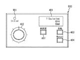
図4に示すX線制御操作パネル400には、表示パネル401、ボリューム402、自動スイッチ(オートSW)403、マニュアルスイッチ(マニュアルSW)404及び再指定スイッチ(再指定SW)407が設けられている。
FIG. 4 is a schematic diagram showing an example of the X-ray
The X-ray
表示パネル401は、X線発生装置100から照射するX線に係る情報を表示したり、システムの状態を表示したりするパネルである。ボリューム402は、透視線量(X線発生装置100から照射するX線のX線量)の変更を行う際に操作者が操作するものである。オートSW403は、透視線量(X線発生装置100から照射するX線のX線量)の制御を自動で行いたい場合に操作者が操作(押下)するスイッチである。マニュアルSW404は、ボリューム402を用いた透視線量の変更を行う際に操作者が操作(押下)するスイッチである。再指定SW407は、透視線量(X線発生装置100から照射するX線のX線量)を所定のレベル(既定の値)に戻す際に操作者が操作(押下)する操作手段のスイッチである。
The
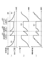
図5は、本発明の第1の実施形態を示し、透視線量、ノイズ量及び画像補正量の相関の一例を示す模式図である。ここで、図5において、タイミング501は、再指定SW407を押下する最初のタイミングを表しており、また、タイミング502は、再指定SW407を押下する2回目のタイミングを表している。
FIG. 5 is a schematic diagram illustrating an example of the correlation between the fluoroscopic dose, the noise amount, and the image correction amount according to the first embodiment of this invention. Here, in FIG. 5, the
図5(a)は、システム制御部103が透視線量制御部115を通して制御する透視線量505の時間的な変化の経過を示している。再指定SW407が押下された場合、図5(a)に示す透視線量505は、予め設定された上限レベル(上限値)503に復帰する。1回目のタイミング501は、透視線量505が予め設定された下限レベル(下限値)504に到達した後で再指定SW407が押下された場合である。2回目のタイミング502は、透視線量505が下限レベル(下限値)504に到達する前の時点で再指定SW407が押下された場合である。どちらのタイミングの場合においても、再指定SW407が押下された時点で、透視線量505が既定の値である上限レベル(上限値)503まで復帰する。
FIG. 5A shows a temporal change of the
ここで、図5(a)に示す透視線量505の上限レベル(上限値)503及び下限レベル(下限値)504は、被写体202の診断部位(撮影部位)により、予め設定されたものである。この上限レベル(上限値)503及び下限レベル(下限値)504は、例えば、操作者が操作パネル110を介して入力した操作情報に基づいて、システム制御部103が設定を行う。このシステム制御部103で設定した上限レベル(上限値)503及び下限レベル(下限値)504の設定値は、例えば、システム制御部103により、記録媒体であるFlashメモリ118の所定のエリアに記録(設定)されている。
Here, the upper limit level (upper limit value) 503 and the lower limit level (lower limit value) 504 of the
図5(b)は、透視線量505の時間的な変化に伴い、イメージセンサ101から出力される透視画像(X線画像)のアナログ信号に発生するノイズ量511の時間的な変化の経過を示している。この図5(b)には、図5(a)に示す透視線量505の低下に応じて、ノイズ量511が増加していくことが示されている。
FIG. 5B shows a temporal change of the
図5(c)は、画像補正部105が、システム制御部103の制御に基づいて、透視線量505の時間的な変化に伴って発生するノイズ量511を低減させるために行う画像補正処理での画像補正量521の時間的な変化の経過を示している。
FIG. 5C shows an image correction process performed by the
図5(c)に示すように、再指定SW407の1回目の押下のタイミング501では、画像補正部105は、透視線量505の上限レベル(上限値)503への変更に伴って、画像補正量が最低レベルに戻るような処理を行う。また、再指定SW407の2回目の押下のタイミング502では、画像補正部105は、画像補正量が途中の段階であっても、透視線量505が上限レベル(上限値)503にまで復帰しているため、画像補正量を最低レベルに戻すような処理を行う。即ち、システム制御部103は、再指定SW407が押下された場合に、画像補正部105に対して、透視線量505の上限レベル(上限値)503への変更に伴って、画像補正量を低下させる変更の制御を行う。
As shown in FIG. 5C, at the first
図5に示すこれらの一連の処理は、システム制御部103が、計時部111の時間的変化や操作パネル110からの操作に応じて、透視線量制御部115や画像補正部105に対する設定値を制御することで実現される。また、図5(a)に示す透視線量505の変化量は、予めFlashメモリ118に記録されている基本変化量が適用される。また、透視線量505の変化に対する画像補正部105の画像補正量は、予めFlashメモリ118の所定のエリアに記録されている基本補正量が適用される。
In the series of processes shown in FIG. 5, the
図6は、本発明の第1の実施形態に係るX線画像処理装置(放射線画像処理装置)102の画像補正部105の詳細な構成の一例を示すブロック図である。
FIG. 6 is a block diagram illustrating an example of a detailed configuration of the
図6に示すように、画像補正部105は、階調補正処理部600、平均値フィルタ601、高域強調フィルタ602及び係数設定部603を有して構成されている。
As shown in FIG. 6, the
階調補正処理部600は、画像入力部104から入力されるX線画像(透視画像)の輝度レベルを補正する、覆い焼き補正等の各種の階調補正の処理を行うものである。平均値フィルタ601は、ノイズの除去を行うフィルタである。高域強調フィルタ602は、平均値フィルタ601により輪郭があいまいになったX線画像の高周波成分を強調して先鋭化するフィルタである。係数設定部603は、階調補正処理部600や平均値フィルタ601、高域強調フィルタ602に対して、それぞれの処理量の多少を決めるための補正係数を設定するものである。
The gradation
具体的に、係数設定部603は、システム制御部103からシステムバス119を通して指示される画像補正量に応じて、平均値フィルタ601及び高域強調フィルタ602に係数の設定を行う。
Specifically, the
係数設定部603は、この係数の設定に関しては、例えば、以下のように処理を行う。
画像補正量が少ない場合には、階調補正による輝度調整量を少なくすることで暗部の輝度上昇を抑え、且つノイズ除去量が少なくなるように、平均値フィルタ601の処理量が少なく、高域強調フィルタ602の処理量も少なくなるように係数を設定する。また、画像補正量が多い場合には、階調補正による輝度調整量を多くすることで暗部の輝度を上昇させ、且つノイズ除去量が多くなるように、平均値フィルタ601の処理量が多く、高域強調フィルタ602の処理量も多くなるように係数を設定する。
For example, the
When the image correction amount is small, the processing amount of the
なお、図6に示すノイズ除去に係る構成は単なる1つの実施例であり、例えば、メディアンフィルタを使用する方式や、高域強調フィルタ602の代わりに輪郭強調フィルタを使用した方式などのいくつかの形態も本実施形態に適用可能である。
Note that the configuration related to noise removal shown in FIG. 6 is merely one example. For example, there are several methods such as a method using a median filter and a method using a contour enhancement filter instead of the high
次に、本発明の第1の実施形態に係るX線画像処理装置(放射線画像処理装置)102の処理動作について、図3に示すフローチャートを用いて説明を行う。 Next, the processing operation of the X-ray image processing apparatus (radiation image processing apparatus) 102 according to the first embodiment of the present invention will be described using the flowchart shown in FIG.
操作者が表示装置108を見ながら診断を行い、操作者がオートSW403を押下すると、ステップS301において、システム制御部103は、操作制御部109を介してこれを検知する。
When the operator makes a diagnosis while viewing the
続いて、ステップS302において、システム制御部103は、Flashメモリ118の所定のエリアから、上限レベル(上限値)503や下限レベル(下限値)504、変化量等の透視線量505に関する設定値を読み込み、透視線量制御部115に設定する。また、システム制御部103は、Flashメモリ118の所定のエリアから、画像補正量521に関する設定値を読み込み、画像補正部105に設定する。さらに、システム制御部103は、計時部111に対して計時機能の作動を開始させる。
Subsequently, in step S302, the
続いて、ステップS303において、システム制御部103は、計時部111による計時機能の作動と連動して、透視線量制御部115に対して、図5(a)に示す透視線量505に表されるような基本変化量に応じた、透視線量を低下させる制御を行う。これに基づいて、透視線量制御部115は、X線発生装置100に対して、当該X線発生装置100から被写体202に照射するX線のX線量(透視線量)を、予め定められた上限レベル(上限値)503から時間の経過とともに低下させる制御を行う。
Subsequently, in step S303, the
続いて、ステップS304において、システム制御部103は、透視線量を低下させる基本設定量(割合)に応じて、画像補正部105に、図5(c)に示す画像補正量521のような段階的な画像補正量の増加に基づく画像補正処理を実行させる。即ち、システム制御部103は、透視線量の低下に伴う変化量に応じて、画像補正部105による画像補正処理に係る画像補正量を上昇させる制御を行う。
Subsequently, in step S304, the
続いて、ステップS305において、システム制御部103は、ステップS303で開始した透視線量の低下処理における透視線量505を常時監視しており、透視線量505が予め設定した下限レベル(下限値)504に到達したか否かを判断する。
Subsequently, in step S305, the
ステップS305の判断の結果、透視線量505が予め設定した下限レベル(下限値)504に到達した場合には、ステップS306に進む。
As a result of the determination in step S305, when the
ステップS306に進むと、システム制御部103は、透視線量505を当該下限レベル(下限値)504で維持するための制御を透視線量制御部115に対して行うと共に、現時点の画像補正量521を維持するための制御を画像補正部105に対して行う。
In step S306, the
ステップS306の処理が終了した場合、或いは、ステップS305において透視線量505が予め設定した下限レベル(下限値)504に到達していないと判断された場合には、ステップS307に進む。
When the process of step S306 is completed, or when it is determined in step S305 that the
ステップS307に進むと、システム制御部103は、図4に示すX線制御操作パネル400に対して、操作者により当該オートSW403以外の他のスイッチの操作(押下)があったか否かを判断する。この判断の結果、X線制御操作パネル400に対して、操作者により当該オートSW403以外の他のスイッチの操作(押下)が無かった場合には、ステップS308に進む。
In step S307, the
ステップS308に進むと、システム制御部103は、透視線量505が予め設定した下限レベル(下限値)504に到達したか否かを判断する。この判断の結果、透視線量505が予め設定した下限レベル(下限値)504に到達した場合には、ステップS306に戻り、また、透視線量505が予め設定した下限レベル(下限値)504に到達していない場合には、ステップS303に戻る。
In step S308, the
一方、ステップS307の判断の結果、X線制御操作パネル400に対して、操作者により当該オートSW403以外の他のスイッチの操作(押下)があった場合には、ステップS309に進む。
On the other hand, as a result of the determination in step S307, if the operator operates (presses) other switches than the
ステップS309に進むと、システム制御部103は、X線制御操作パネル400に対して、操作者により操作(押下)されたスイッチの種類を判断する。この判断の結果、操作者により操作(押下)されたスイッチが再指定SW407である場合には、ステップS310に進む。
In step S309, the
ステップS310に進むと、システム制御部103は、透視線量制御部115に対して、透視線量505を上限レベル(上限値)503に復帰させる再設定を行う。これに基づいて、透視線量制御部115は、X線発生装置100に対して、当該X線発生装置100から被写体202に照射するX線のX線量(透視線量)を上限レベル(上限値)503に復帰させる制御を行う。
In step S <b> 310, the
続いて、ステップS311において、システム制御部103は、透視線量505を上限レベル(上限値)503に復帰させる制御に基づいて、画像補正部105に、図5(c)に示す画像補正量521を初期設定値にまで復帰させる処理を行わせる。即ち、画像補正部105では、図5(c)に示すように、画像補正量を最低レベルに戻した画像処理を行う。このステップS311の処理が終了すると、ステップS303に戻る。
Subsequently, in step S311, the
一方、ステップS309の判断の結果、操作者により操作(押下)されたスイッチがマニュアルSW404である場合には、ステップS312に進む。
On the other hand, if the result of determination in step S309 is that the switch operated (pressed) by the operator is
ステップS312に進むと、システム制御部103は、オートSW403による全ての自動制御処理を停止し、その時点での全ての処理パラメータを保持したまま、マニュアルSW404によるマニュアル操作へ移行する制御を行う。そして、図3に示すフローチャートにおける処理動作が終了する。
In step S312, the
(第2の実施形態)
以下、図7〜図9を参照しながら、本発明の第2の実施形態を説明する。
本発明の第2の実施形態に係るX線画像処理システム(放射線画像処理システム)の全体構成については、図1に示す第1の実施形態に係るX線画像処理システム(放射線画像処理システム)と同様である。
(Second Embodiment)
Hereinafter, a second embodiment of the present invention will be described with reference to FIGS.
The overall configuration of the X-ray image processing system (radiation image processing system) according to the second embodiment of the present invention is the same as that of the X-ray image processing system (radiation image processing system) according to the first embodiment shown in FIG. It is the same.
図7は、本発明の第2の実施形態に係るX線画像処理装置(放射線画像処理装置)102による処理動作の一例を示すフローチャートである。なお、図7に示すフローチャートにおいて、第1の実施形態における図3に示すフローチャートと同様のステップについては、同じステップ番号を付している。また、このフローチャートの処理動作については、後述する。 FIG. 7 is a flowchart showing an example of a processing operation performed by the X-ray image processing apparatus (radiation image processing apparatus) 102 according to the second embodiment of the present invention. In the flowchart shown in FIG. 7, the same steps as those in the flowchart shown in FIG. 3 in the first embodiment are denoted by the same step numbers. The processing operation of this flowchart will be described later.
図8は、本発明の第2の実施形態を示し、透視線量、ノイズ量及び画像処理量の相関の一例を示す模式図である。なお、図8において、第1の実施形態における図5に示す模式図と同様のものについては、同じ符号を付している。 FIG. 8 is a schematic diagram illustrating an example of the correlation between the fluoroscopic dose, the noise amount, and the image processing amount according to the second embodiment of this invention. In FIG. 8, the same reference numerals are assigned to the same components as those in the schematic diagram shown in FIG. 5 in the first embodiment.
また、第2の実施形態では、第1の実施形態における図4に示すX線制御操作パネル400に代えて、図9に示すX線制御操作パネル900を適用する。
In the second embodiment, an X-ray
図9は、本発明の第2の実施形態を示し、X線制御操作パネル900の一例を示す模式図である。なお、図9において、第1の実施形態における図4に示すX線制御操作パネル400と同様の構成については、同じ符号を付している。即ち、第2の実施形態におけるX線制御操作パネル900には、図4に示すX線制御操作パネル400の構成に加えて、イニシャルスイッチ(イニシャルSW)901が設けられている。このイニシャルSW901は、再設定された、図8に示す上限レベル(上限値)806及び下限レベル(下限値)807を予め定められた初期設定状態の上限レベル(上限値)503及び下限レベル(下限値)504に変更させるためのスイッチである。
FIG. 9 is a schematic diagram illustrating an example of the X-ray
まず、以下に、図8の模式図の説明を行う。
図8において、タイミング801は、図9の再指定SW407を押下する最初のタイミングを表しており、タイミング802は、再指定SW407を押下する2回目のタイミングを表している。また、タイミング803は、図9のイニシャルSW901を押下するタイミングを表している。
First, the schematic diagram of FIG. 8 will be described below.
In FIG. 8, the
図8(a)は、システム制御部103が透視線量制御部115を通して制御する透視線量805の時間的な変化の経過を示している。上限レベル(上限値)806及び下限レベル(下限値)807は、それぞれ、再設定された上限レベル(上限値)及び下限レベル(下限値)である。
FIG. 8A shows a temporal change of the
図8(b)は、透視線量805の時間的な変化に伴い、イメージセンサ101から出力される透視画像(X線画像)のアナログ信号に発生するノイズ量811の時間的な変化の経過を示している。この図8(b)には、図8(a)に示す透視線量805の低下に応じて、ノイズ量811が増加していくことが示されている。
FIG. 8B shows the change of the amount of
図8(c)は、画像補正部105が、システム制御部103の制御に基づいて、透視線量805の時間的な変化に伴って発生するノイズ量811を低減するために行う画像補正処理での画像補正量821の時間的な変化の経過を示している。
FIG. 8C shows an image correction process performed by the
1回目のタイミング801は、透視線量805が予め定められた初期設定状態の下限レベル(下限値)504に達した後で再指定SW407が押下された場合である。この場合、システム制御部103は、操作者が、予め設定されている下限レベル(下限値)504での診断を許容したと判断し、下限レベル(下限値)504の再設定は行わない。そして、この場合、システム制御部103は、操作者が、下限レベル(下限値)504までの診断を許容したということで、上限レベル(上限値)503を下げるための再設定を行う。この再設定処理により再設定された、予め定められた上限レベル(上限値)503よりも小さい値である上限レベル(上限値)806の設定値は、システム制御部103により、記録媒体であるFlashメモリ118の所定のエリアに記録(設定)される。この再設定された既定の値である上限レベル(上限値)806は、イニシャルSW901が押下されるタイミング803まで適用され続ける。即ち、本実施形態では、再指定SW407が押下された条件により、透視線量805を、上限レベル(上限値)806に戻す変更がなされる。
The
2回目のタイミング802は、透視線量805が予め定められた初期設定状態の下限レベル(下限値)504に到達する前の時点で再指定SW407が押下された場合である。この場合、システム制御部103は、操作者が、下限レベル(下限値)504での診断が困難であるという理由で再指定SW407を押下したと判断し、下限レベル(下限値)504を上昇させるための再設定を行う。即ち、透視線量制御部115は、当該再指定SW407が押下された時点の透視線量805を新たな下限レベル(下限値)807として、透視線量805を低下させる処理を行う。この再設定処理により再設定された下限レベル(下限値)807の設定値は、システム制御部103により、記録媒体であるFlashメモリ118の所定のエリアに記録(設定)される。この再設定された下限レベル(下限値)807は、イニシャルSW901が押下されるタイミング803まで適用され続ける。
The
システム制御部103は、透視線量制御部115に対する透視線量に係る設定値に応じて、Flashメモリ118から画像補正量に係る設定値を読み出し、画像補正部105に設定する。
The
次に、本発明の第2の実施形態に係るX線画像処理装置(放射線画像処理装置)102の処理動作について、図7に示すフローチャートを用いて説明を行う。 Next, the processing operation of the X-ray image processing apparatus (radiation image processing apparatus) 102 according to the second embodiment of the present invention will be described using the flowchart shown in FIG.
操作者が表示装置108を見ながら診断を行い、操作者がオートSW403を押下すると、ステップS301において、システム制御部103は、操作制御部109を介してこれを検知する。
When the operator makes a diagnosis while viewing the
続いて、ステップS302において、システム制御部103は、Flashメモリ118から、上限レベル(上限値)503や下限レベル(下限値)504、変化量等の透視線量805に関する初期設定値を読み込み、透視線量制御部115に設定する。また、システム制御部103は、Flashメモリ118から、画像補正量821に関する初期設定値を読み込み、画像補正部105に設定する。さらに、システム制御部103は、計時部111に対して計時機能の作動を開始させる。
Subsequently, in step S302, the
続いて、ステップS303において、システム制御部103は、計時部111による計時機能の作動と連動して、透視線量制御部115に対して、図8(a)に示す透視線量805に表されるような基本変化量に応じた、透視線量を低下させる制御を行う。これに基づいて、透視線量制御部115は、X線発生装置100に対して、当該X線発生装置100から被写体202に照射するX線のX線量(透視線量)を、予め定められた上限レベル(上限値)503から時間の経過とともに低下させる制御を行う。
Subsequently, in step S303, the
続いて、ステップS304において、システム制御部103は、透視線量を低下させる基本設定量に応じて、画像補正部105に、図8(c)に示す画像補正量821のような段階的な画像補正量の増加に基づく画像補正処理を実行させる。即ち、システム制御部103は、透視線量の低下に伴う変化量に応じて、画像補正部105による画像補正処理に係る画像補正量を上昇させる制御を行う。
Subsequently, in step S304, the
続いて、ステップS305において、システム制御部103は、ステップS303で開始した透視線量の低下処理における透視線量805を常時監視しており、透視線量805が予め設定した下限レベル(下限値)504に到達したか否かを判断する。
Subsequently, in step S305, the
ステップS305の判断の結果、透視線量805が予め設定した下限レベル(下限値)504に到達した場合には、ステップS306に進む。
As a result of the determination in step S305, when the
ステップS306に進むと、システム制御部103は、透視線量805を当該下限レベル(下限値)504で維持するための制御を透視線量制御部115に対して行うと共に、現時点の画像補正量821を維持するための制御を画像補正部105に対して行う。
In step S306, the
ステップS306の処理が終了した場合、或いは、ステップS305において透視線量805が予め設定した下限レベル(下限値)504に到達していないと判断された場合には、ステップS307に進む。
When the process of step S306 is completed, or when it is determined in step S305 that the
ステップS307に進むと、システム制御部103は、図9に示すX線制御操作パネル900に対して、操作者により当該オートSW403以外の他のスイッチの操作(押下)があったか否かを判断する。この判断の結果、X線制御操作パネル900に対して、操作者により当該オートSW403以外の他のスイッチの操作(押下)が無かった場合には、ステップS308に進む。
In step S307, the
ステップS308に進むと、システム制御部103は、透視線量805が予め設定した下限レベル(下限値)504に到達したか否かを判断する。この判断の結果、透視線量805が予め設定した下限レベル(下限値)504に到達した場合には、ステップS306に戻り、また、透視線量805が予め設定した下限レベル(下限値)504に到達していない場合には、ステップS303に戻る。
In step S308, the
一方、ステップS307の判断の結果、X線制御操作パネル900に対して、操作者により当該オートSW403以外の他のスイッチの操作(押下)があった場合には、ステップS701に進む。
On the other hand, as a result of the determination in step S307, if the operator operates (presses) other switches than the
ステップS701に進むと、システム制御部103は、X線制御操作パネル900に対して、操作者により操作(押下)されたスイッチの種類を判断する。この判断の結果、操作者により操作(押下)されたスイッチがイニシャルSW901である場合には、ステップS302に戻る。
In step S701, the
また、ステップS701の判断の結果、操作者により操作(押下)されたスイッチが再指定SW407である場合には、ステップS702に進む。ステップS702に進むと、システム制御部103は、現時点での透視線量805が初期設定状態の下限レベル(下限値)504に到達しているか否かを判断する。
If it is determined in step S701 that the switch operated (pressed) by the operator is the
ステップS702の判断の結果、現時点での透視線量805が初期設定状態の下限レベル(下限値)504に到達していない場合(例えば、図8に示すタイミング802の場合)には、ステップS703に進む。ステップS703に進むと、システム制御部103は、再指定SW407が押下された時点での透視線量805を下限レベル(下限値)807として、Flashメモリの所定のエリアに対して記録し、下限レベル(下限値)の再設定を行う。
As a result of the determination in step S702, when the
ステップS703の処理が終了した場合、或いは、ステップS702において現時点の透視線量805が初期設定状態の下限レベル(下限値)504に到達していると判断された場合(例えば、図8に示すタイミング801の場合)には、ステップS704に進む。
When the process of step S703 is completed, or when it is determined in step S702 that the current
ステップS704に進むと、システム制御部103は、初期設定状態の上限レベル(上限値)503を上限レベル(上限値)806に下げるための再設定を行う。そして、システム制御部103は、Flashメモリの所定のエリアに対して、再設定を行う上限レベル(上限値)806の設定値を記録する。
In step S704, the
続いて、ステップS310において、システム制御部103は、透視線量制御部115に対して、透視線量805を上限レベル(上限値)806に復帰させる再設定を行う。これに基づいて、透視線量制御部115は、X線発生装置100に対して、当該X線発生装置100から被写体202に照射するX線のX線量(透視線量)を上限レベル(上限値)806に復帰させる制御を行う。
Subsequently, in step S <b> 310, the
続いて、ステップS311において、システム制御部103は、透視線量805を上限レベル(上限値)806に復帰させる制御に基づいて、画像補正部105に、図8(c)に示す画像補正量821を透視線量805にあわせた設定値に再設定する。このステップS311の処理が終了すると、ステップS303に戻る。
Subsequently, in step S311, the
一方、ステップS701の判断の結果、操作者により操作(押下)されたスイッチがマニュアルSW404である場合には、ステップS312に進む。
On the other hand, if the result of determination in step S701 is that the switch operated (pressed) by the operator is
ステップS312に進むと、システム制御部103は、オートSW403による全ての自動制御処理を停止し、その時点での全ての処理パラメータを保持したまま、マニュアルSW404によるマニュアル操作へ移行する制御を行う。そして、図7に示すフローチャートにおける処理動作が終了する。
In step S312, the
(第3の実施形態)
以下、図10〜図12を参照しながら、本発明の第3の実施形態を説明する。
本発明の第3の実施形態に係るX線画像処理システム(放射線画像処理システム)の全体構成については、図1に示す第1の実施形態に係るX線画像処理システム(放射線画像処理システム)と同様である。
(Third embodiment)
The third embodiment of the present invention will be described below with reference to FIGS.
The overall configuration of the X-ray image processing system (radiation image processing system) according to the third embodiment of the present invention is the same as that of the X-ray image processing system (radiation image processing system) according to the first embodiment shown in FIG. It is the same.
図10は、本発明の第3の実施形態に係るX線画像処理装置(放射線画像処理装置)102による処理動作の一例を示すフローチャートである。なお、図10に示すフローチャートにおいて、第1の実施形態における図3に示すフローチャートと同様のステップについては、同じステップ番号を付している。また、このフローチャートの処理動作については、後述する。 FIG. 10 is a flowchart showing an example of a processing operation performed by the X-ray image processing apparatus (radiation image processing apparatus) 102 according to the third embodiment of the present invention. In the flowchart shown in FIG. 10, the same step numbers are assigned to the same steps as those in the flowchart shown in FIG. 3 in the first embodiment. The processing operation of this flowchart will be described later.
また、第3の実施形態では、第1の実施形態における図4に示すX線制御操作パネル400(第2の実施形態における図9に示すX線制御操作パネル900)に代えて、図11に示すX線制御操作パネル1100を適用する。
Further, in the third embodiment, instead of the X-ray control operation panel 400 (X-ray
図11は、本発明の第3の実施形態を示し、X線制御操作パネル1100の一例を示す模式図である。なお、図11において、第2の実施形態における図9に示すX線制御操作パネル900と同様の構成については、同じ符号を付している。即ち、第3の実施形態におけるX線制御操作パネル1100には、図9に示すX線制御操作パネル900の構成に加えて、各種のスイッチ1101〜1105が設けられている。
FIG. 11 is a schematic diagram showing an example of the X-ray
上限スイッチ(上限SW)1101は、上限レベル(上限値)を変更する場合に操作者が操作(押下)するスイッチである。下限スイッチ(下限SW)1102は、下限レベル(下限値)を変更する場合に操作者が操作(押下)するスイッチである。入力スイッチ(入力SW)1103は、上限SW1101による上限レベルの変更や下限SW1102による下限レベルの変更を設定する場合に操作者が操作(押下)するスイッチである。メモリ1スイッチ(メモリ1SW)1104及びメモリ2スイッチ(メモリ2SW)1105は、設定した任意の上限レベルや下限レベルを記録する場合に操作者が操作(押下)するスイッチである。
The upper limit switch (upper limit SW) 1101 is a switch operated (pressed) by the operator when changing the upper limit level (upper limit value). The lower limit switch (lower limit SW) 1102 is a switch operated (pressed) by the operator when changing the lower limit level (lower limit value). The input switch (input SW) 1103 is a switch operated (pressed) by the operator when setting a change in the upper limit level by the
図12は、本発明の第3の実施形態を示し、透視線量、ノイズ量及び画像処理量の相関の一例を示す模式図である。ここで、図12において、タイミング1201は、再指定SW407を押下する最初のタイミングを表しており、また、タイミング1202は、再指定SW407を押下する2回目のタイミングを表している。
FIG. 12 is a schematic diagram illustrating an example of the correlation among the fluoroscopic dose, the noise amount, and the image processing amount according to the third embodiment of this invention. Here, in FIG. 12, the
図12(a)は、システム制御部103が透視線量制御部115を通して制御する透視線量1205の時間的な変化の経過を示している。再指定SW407が押下された場合、図12(a)に示す透視線量1205は、予め設定された上限レベル(上限値)1203に復帰する。1回目のタイミング1201は、透視線量1205が予め設定された下限レベル(下限値)1204に到達した後で再指定SW407が押下された場合である。2回目のタイミング1202は、透視線量1205が下限レベル(下限値)1204に到達する前の時点での再指定SW407が押下された場合である。どちらのタイミングの場合においても、再指定SW407が押下された時点で、透視線量1205が既定の値である上限レベル(上限値)1203まで復帰する。
FIG. 12A shows a temporal change of the
ここで、図12(a)に示す透視線量1205の上限レベル(上限値)1203及び下限レベル(下限値)1204は、被写体202の診断部位(撮影部位)により予め設定されたもの、もしくは操作者により任意に設定されたものである。この診断部位により予め設定された上限レベル(上限値)1203及び下限レベル(下限値)1204の設定値は、例えば、システム制御部103により、記録媒体であるFlashメモリ118の所定のエリアに予め記録(設定)されている。また、操作者により任意に設定した上限レベル及び下限レベルの設定値は、例えば、システム制御部103により、被写体202の診断部位により予め設定された設定値とは異なるFlashメモリ118のエリアに記録(設定)される。
Here, the upper limit level (upper limit value) 1203 and the lower limit level (lower limit value) 1204 of the
図12(b)は、透視線量1205の時間的な変化に伴い、イメージセンサ101から出力される透視画像(X線画像)のアナログ信号に発生するノイズ量1211の時間的な変化の経過を示している。この図12(b)には、図12(a)に示す透視線量1205の低下に応じて、ノイズ量1211が増加していくことが示されている。
FIG. 12B shows a temporal change of the
図12(c)は、画像補正部105が、システム制御部103の制御に基づいて、透視線量1205の時間的な変化に伴って発生するノイズ量1211を低減するために行う画像補正処理での画像補正量1221の時間的な変化の経過を示している。
FIG. 12C illustrates an image correction process performed by the
図12(c)に示すように、再指定SW407の1回目の押下のタイミング1201では、画像補正部105は、透視線量1205の上限レベル(上限値)503への変更に伴って、画像補正量が最低レベルに戻るような処理を行う。また、再指定SW407の2回目の押下のタイミング1202では、画像補正部105は、画像補正量が途中の段階であっても、透視線量1205が上限レベル(上限値)1203にまで復帰しているため、画像補正量を最低レベルに戻すような処理を行う。即ち、システム制御部103は、再指定SW407が押下された場合に、画像補正部105に対して、透視線量1205の上限レベル(上限値)1203への変更に伴って、画像補正量を低下させる変更の制御を行う。
As shown in FIG. 12C, at the first
図12に示すこれらの一連の処理は、システム制御部103が、計時部111の時間的変化や操作パネル110からの操作に応じて、透視線量制御部115や画像補正部105に対する設定値を制御することで実現される。また、図12(a)に示す透視線量1205の変化量は、予めFlashメモリ118に記録されている基本変化量が適用される。また、透視線量1205の変化に対する画像補正部105の画像補正量は、予めFlashメモリ118の所定のエリアに記録されている基本補正量が適用される。
In these series of processes shown in FIG. 12, the
次に、本発明の第3の実施形態に係るX線画像処理装置(放射線画像処理装置)102の処理動作について、図10に示すフローチャートを用いて説明を行う。 Next, the processing operation of the X-ray image processing apparatus (radiation image processing apparatus) 102 according to the third embodiment of the present invention will be described using the flowchart shown in FIG.
まず、メモリ1SW1104及びメモリ2SW1105による上限レベル(上限値)及び下限レベル(下限値)の設定値の記録方法、並びに、一時的な上限レベル(上限値)及び下限レベル(下限値)の設定方法について説明する。 First, a recording method of setting values of upper limit level (upper limit value) and lower limit level (lower limit value) by memory 1SW 1104 and memory 2SW 1105, and a setting method of temporary upper limit level (upper limit value) and lower limit level (lower limit value). explain.
ステップS1001において、システム制御部103は、図11に示すX線制御操作パネル1100に対して、操作者によりスイッチの操作(押下)があったか否かを判断する。具体的に、このステップS1001では、図11に示すX線制御操作パネル1100のスイッチのうち、上限SW1101又は下限SW1102の操作があったか否か、オートSW403の操作があったか否か、並びに、メモリSW(メモリ1SW1104、メモリ2SW1105)の操作後にオートSW403の操作があったか否かの判断がされ、それ以外のスイッチが操作された場合でも、ステップS1001での待機状態となる。
In step S1001, the
ステップS1001の判断の結果、上限SW1101又は下限SW1102の操作(押下)があった場合には、ステップS1002に進む。ステップS1002に進むと、システム制御部103は、操作者が、ボリューム402の操作に応じて変化する表示パネル401上の透視線量値を見ながら上限レベル(上限値)又は下限レベル(下限値)の調整を行うと、これを検出する。
If the result of determination in step S1001 is that there is an operation (pressing) of the
続いて、ステップS1003において、システム制御部103は、操作者により入力SW1103が操作(押下)されたことを検知すると、ステップS1002で調整された透視線量の上限レベル(上限値)又は下限レベル(下限値)を一時記録する。具体的に、システム制御部103は、入力SW1103が押下された時点での透視線量における上限レベル(上限値)又は下限レベル(下限値)を、Flashメモリ118の一時記録エリアに一時記録する。ここまでの処理動作が、一時的な上限レベル(上限値)及び下限レベル(下限値)の設定方法である。
Subsequently, in step S1003, when the
入力SW1103の操作(押下)が行われた後に、続いて、ステップS1004において、システム制御部103は、操作者によりメモリSW(メモリ1SW1104又はメモリ2SW1105)の操作(押下)があったか否かを判断する。
After the operation (pressing) of the
ステップS1004の判断の結果、操作者によりメモリSW(メモリ1SW1104又はメモリ2SW1105)の操作(押下)があった場合には、ステップS1005に進む。 As a result of the determination in step S1004, if the operator operates (presses) the memory SW (memory 1SW 1104 or memory 2SW 1105), the process proceeds to step S1005.
ステップS1005に進むと、システム制御部103は、ステップS1003でFlashメモリ118の一時記録エリアに記録していた設定値を、操作されたメモリSWの種類に応じて同じFlashメモリ118の対応するメモリエリアに記録する変更を行う。具体的に、メモリ1SW1104が操作(押下)された場合には、システム制御部103は、ステップS1003でFlashメモリ118の一時記録エリアに一時記録していた設定値を、Flashメモリ118のメモリ1エリアに記録する。また、メモリ2SW1105が操作(押下)された場合には、システム制御部103は、ステップS1003でFlashメモリ118の一時記録エリアに一時記録していた設定値を、Flashメモリ118のメモリ2エリアに記録する。
In step S1005, the
一方、ステップS1004の判断の結果、操作者によりメモリSW(メモリ1SW1104又はメモリ2SW1105)の操作(押下)がなかった場合には、ステップS1001に戻る。 On the other hand, as a result of the determination in step S1004, if the operator has not operated (pressed) the memory SW (memory 1SW 1104 or memory 2SW 1105), the process returns to step S1001.
以上が、メモリ1SW1104及びメモリ2SW1105による上限レベル(上限値)及び下限レベル(下限値)の設定値の記録方法である。
The above is the recording method of the set values of the upper limit level (upper limit value) and the lower limit level (lower limit value) by the memory 1SW 1104 and the
次に、第1の実施形態における自動制御、一時的に設定した上限レベルや下限レベルでの自動制御、メモリSWを利用した自動制御の処理動作について説明する。 Next, processing operations of automatic control, automatic control at the temporarily set upper limit level and lower limit level, and automatic control using the memory SW in the first embodiment will be described.
ステップS1001の判断の結果、上限SW1101又は下限SW1102やメモリSW(メモリ1SW1104、メモリ2SW1105)の操作(押下)がない状況で、オートSW403の操作(押下)があった場合には、ステップS1007に進む。この場合、ステップS1007に進むと、システム制御部103は、診断部位により予め設定された透視線量の上限レベル及び下限レベルのそれぞれの設定値を、Flashメモリ118の所定エリアから読み出す。そして、システム制御部103は、読み出した透視線量の上限レベル及び下限レベルの設定値を、図12(a)に示す上限レベル(上限値)1203及び下限レベル(下限値)1204として透視線量制御部115に設定する。さらに、このステップS1007では、Flashメモリ118の所定のエリアから画像補正量1221に関する設定値が読み出されて画像補正部105に設定され、また、計時部111による計時機能の作動が開始される。
If the result of the determination in step S1001 is that there is no operation (pressing) of the
また、ステップS1001において上限SW1101又は下限SW1102の操作(押下)があったと判断され、ステップS1002及びS1003の処理を経た後、ステップS1004においてメモリSW(メモリ1SW1104又はメモリ2SW1105)の操作(押下)がなかった状況で再びステップS1001に戻り、当該ステップS1001において、オートSW403の操作(押下)があったと判断された場合にも、ステップS1007に進む。
In step S1001, it is determined that the
この場合、ステップS1007に進むと、システム制御部103は、ステップS1003でFlashメモリ118の一時記録エリアに一時記録された上限レベル(上限値)又は下限レベル(下限値)の設定値を読み出す。そして、システム制御部103は、ステップS1003でFlashメモリ118に一時記録させた上限レベル又は下限レベルの設定値を、診断部位により予め設定された上限レベル及び下限レベルの設定値よりも優先させて、図12(a)に示す上限レベル(上限値)1203及び下限レベル(下限値)1204の設定を透視線量制御部115に対して行う。例えば、ステップS1003の複数回の処理によりFlashメモリ118に上限レベル及び下限レベルの両方の設定値が一時記録されている場合には、これらの設定値に基づいて上限レベル(上限値)1203及び下限レベル(下限値)1204の設定が行われる。さらに、このステップS1007では、Flashメモリ118の所定のエリアから画像補正量1221に関する設定値が読み出されて画像補正部105に設定され、また、計時部111による計時機能の作動が開始される。
In this case, in step S1007, the
また、ステップS1001の判断の結果、メモリSW(メモリ1SW1104、メモリ2SW1105)の操作後にオートSW403の操作があった場合には、ステップS1006に進む。
If it is determined in step S1001 that the
ステップS1006に進むと、システム制御部103は、ステップS1005でFlashメモリ118のメモリエリア(メモリ1エリア又はメモリ2エリア)に記録された上限レベル(上限値)又は下限レベル(下限値)の設定値を読み出す。この場合、メモリ1エリア及びメモリ2エリアに重複して上限レベル(上限値)又は下限レベル(下限値)の設定値が記録されている場合には、後に記録された設定値が読み出される。そして、このステップS1006では、読み出した設定値に基づく設定値の変更指示がなされ、ステップS1007に進む。
In step S1006, the
この場合、ステップS1007に進むと、システム制御部103は、ステップS1006でFlashメモリ118のメモリエリアから読み出した上限レベル又は下限レベルの設定値を、診断部位により予め設定された上限レベル及び下限レベルの設定値よりも優先させて、図12(a)に示す上限レベル(上限値)1203及び下限レベル(下限値)1204の設定を透視線量制御部115に対して行う。さらに、このステップS1007では、Flashメモリ118の所定のエリアから画像補正量1221に関する設定値が読み出されて画像補正部105に設定され、また、計時部111による計時機能の作動が開始される。
In this case, when the process proceeds to step S1007, the
ステップS1007の処理が終了すると、図3に示すステップS303〜S308の処理を経る。 When the process of step S1007 is completed, the process of steps S303 to S308 shown in FIG. 3 is performed.
そして、ステップS307において操作者によりX線制御操作パネル1100の当該オートSW403以外の他のスイッチ(再指定SW407、マニュアルSW404及びイニシャルSW901)の操作があったと判断された場合には、ステップS1008に進む。
If it is determined in step S307 that the operator has operated other switches (re-designated
ステップS1008に進むと、システム制御部103は、X線制御操作パネル1100に対して、操作者により操作(押下)されたスイッチの種類を判断する。この判断の結果、操作者により操作(押下)されたスイッチが再指定SW407である場合には、図3に示すステップS310及びS311の処理を経た後、ステップS304に戻る。
In step S1008, the
また、ステップS1008の判断の結果、操作者により操作(押下)されたスイッチがマニュアルSW404である場合には、図3に示すステップS312の処理を経た後、図10に示すフローチャートにおける処理動作が終了する。
Further, as a result of the determination in step S1008, if the switch operated (pressed) by the operator is the
また、ステップS1008の判断の結果、操作者により操作(押下)されたスイッチがイニシャルSW901である場合には、ステップS1009に進む。ステップS1009に進むと、システム制御部103は、ステップS1007で設定した設定値を初期化する処理を行う。その後、ステップS1001に戻り、ステップS1001以降の処理を再度行う。なお、本実施形態では、ステップS1009の処理が終了した後に処理をステップS1001に移行させるようにしているが、ステップS1007に移行させるようにする形態であってもよい。この場合、例えば、ステップS1007では、オートSW403のみが操作された場合の設定値を設定する形態を採る。
If it is determined in step S1008 that the switch operated (pressed) by the operator is the
(第4の実施形態)
前述した本発明の諸実施形態に係るX線画像処理装置102を構成する図1の各構成部、並びにX線画像処理方法を示す図3、図7及び図10の各ステップは、コンピュータのRAMやROMなどに記憶されたプログラムが動作することによって実現できる。このプログラム及び当該プログラムを記録したコンピュータ読み取り可能な記憶媒体は本発明に含まれる。
(Fourth embodiment)
1 constituting the X-ray
具体的に、前記プログラムは、例えばCD−ROMのような記憶媒体に記録し、或いは各種伝送媒体を介し、コンピュータに提供される。前記プログラムを記録する記憶媒体としては、CD−ROM以外に、フレキシブルディスク、ハードディスク、磁気テープ、光磁気ディスク、不揮発性メモリカード等を用いることができる。他方、前記プログラムの伝送媒体としては、プログラム情報を搬送波として伝搬させて供給するためのコンピュータネットワーク(LAN、インターネットの等のWAN、無線通信ネットワーク等)システムにおける通信媒体を用いることができる。また、この際の通信媒体としては、光ファイバ等の有線回線や無線回線などが挙げられる。 Specifically, the program is recorded in a storage medium such as a CD-ROM, or provided to a computer via various transmission media. As a storage medium for recording the program, a flexible disk, a hard disk, a magnetic tape, a magneto-optical disk, a nonvolatile memory card, and the like can be used in addition to the CD-ROM. On the other hand, as the transmission medium of the program, a communication medium in a computer network (LAN, WAN such as the Internet, wireless communication network, etc.) system for propagating and supplying program information as a carrier wave can be used. In addition, examples of the communication medium at this time include a wired line such as an optical fiber, a wireless line, and the like.
また、本発明は、コンピュータが供給されたプログラムを実行することにより本実施形態に係るX線画像処理装置102の機能が実現される態様に限られない。そのプログラムがコンピュータにおいて稼働しているOS(オペレーティングシステム)或いは他のアプリケーションソフト等と共同して本実施形態に係るX線画像処理装置102の機能が実現される場合も、かかるプログラムは本発明に含まれる。また、供給されたプログラムの処理の全て、或いは一部がコンピュータの機能拡張ボードや機能拡張ユニットにより行われて本実施形態に係るX線画像処理装置102の機能が実現される場合も、かかるプログラムは本発明に含まれる。
Further, the present invention is not limited to a mode in which the function of the X-ray
また、前述した本実施形態は、何れも本発明を実施するにあたっての具体化の例を示したものに過ぎず、これらによって本発明の技術的範囲が限定的に解釈されてはならないものである。すなわち、本発明はその技術思想、またはその主要な特徴から逸脱することなく、様々な形で実施することができる。 In addition, all of the above-described embodiments are merely examples of implementation in carrying out the present invention, and the technical scope of the present invention should not be construed as being limited thereto. . That is, the present invention can be implemented in various forms without departing from the technical idea or the main features thereof.
本発明の諸実施形態に係るX線画像処理装置102では、X線発生装置100から被写体202に照射するX線のX線量を透視線量制御部115で変更する。また、X線発生装置100から被写体202を介して検出されたX線に基づくX線画像に対して、画像補正部105で画像補正処理を行う。そして、システム制御部103において、透視線量制御部115によるX線量の変化に応じて、画像補正部105による画像補正処理に係る画像補正量を変更する制御を行う。
かかる構成によれば、被写体202に照射するX線のX線量を抑えながら、診断等を行うのに十分な画質のX線画像を取得することができる。これにより、被写体202に過大な負荷をかけること無く、X線画像の画質の低下を防止することができる。
In the X-ray
According to this configuration, it is possible to acquire an X-ray image having a sufficient image quality for diagnosis and the like while suppressing the X-ray dose of X-rays irradiated to the subject 202. Thereby, it is possible to prevent the image quality of the X-ray image from deteriorating without imposing an excessive load on the subject 202.
100 X線発生装置(放射線発生装置)
101 イメージセンサ
102 X線画像処理装置(放射線画像処理装置または放射線量制御装置)
103 システム制御部
104 画像入力部
105 画像補正部
106 画像処理部
107 表示制御部
108 表示装置
109 操作制御部
110 操作パネル
111 計時部
112 外部I/F部
113 記録装置制御部
114 記録装置
115 透視線量制御部
116 センサ制御部
117 RAM
118 Flashメモリ
119 システムバス
120 モータ制御部
121 モータ
122 フットペダル
100 X-ray generator (radiation generator)
101
103
118
Claims (13)
前記放射線発生装置から前記被写体を介して検出された放射線に基づく放射線画像に対して画像補正処理を行う画像補正手段と、
前記放射線量変更手段による前記放射線量の低下に応じて、前記画像補正手段による前記画像補正処理に係わる画像補正量を上昇させる制御手段と
を有することを特徴とする放射線画像処理装置。 When the radiation dose irradiated to the subject from the radiation generator is reduced with time, and the radiation dose reaches a predetermined lower limit, the radiation dose is maintained at the lower limit. Change means,
Image correction means for performing image correction processing on a radiation image based on radiation detected from the radiation generation device via the subject;
A radiographic image processing apparatus comprising: a control unit that increases an image correction amount related to the image correction processing by the image correction unit in response to a decrease in the radiation dose by the radiation dose changing unit.
前記制御手段は、前記放射線量の低下に伴う変化量に応じて、前記画像補正量を上昇させる変更を行うことを特徴とする請求項1に記載の放射線画像処理装置。 The radiation dose changing means is for changing the radiation dose with a lapse of time from a predetermined upper limit value,
The radiographic image processing apparatus according to claim 1, wherein the control unit performs a change to increase the image correction amount in accordance with a change amount accompanying a decrease in the radiation dose.
前記放射線量変更手段は、前記操作手段が操作された場合に、前記放射線量を前記既定の値に戻す変更を行い、
前記制御手段は、前記放射線量の前記既定の値への変更に伴って、前記画像補正量を低下させる変更を行うことを特徴とする請求項2又は3に記載の放射線画像処理装置。 It further has an operation means for returning the radiation dose to a predetermined value,
The radiation dose changing means performs a change to return the radiation dose to the predetermined value when the operation means is operated,
The control means, with the change to the predetermined value of the radiation amount, the radiation image processing apparatus according to claim 2 or 3, characterized in that the change of lowering the image correction amount.
前記放射線量変更手段は、前記操作手段が操作された場合に、前記放射線量を、予め定められた上限値よりも小さい値に変更することを特徴とする請求項9に記載の放射線量制御装置。 It further has an operation means for returning the radiation dose to a predetermined value,
The radiation dose control device according to claim 9 , wherein the radiation dose changing unit changes the radiation dose to a value smaller than a predetermined upper limit value when the operation unit is operated. .
前記放射線量変更手段は、前記操作手段が操作された場合に、前記放射線量を、予め定められた上限値に変更することを特徴とする請求項9に記載の放射線量制御装置。 It further has an operation means for returning the radiation dose to a predetermined value,
The radiation dose control device according to claim 9 , wherein the radiation dose changing unit changes the radiation dose to a predetermined upper limit value when the operation unit is operated.
放射線発生装置から被写体に照射する放射線の放射線量を、時間の経過とともに低下させ、当該放射線量が予め定められた下限値に到達した場合には、前記放射線量を前記下限値で維持する放射線量変更手段と、
前記放射線発生装置から前記被写体を介して検出された放射線に基づく放射線画像に対して画像補正処理を行う画像補正手段と、
前記放射線量変更手段による前記放射線量の低下に応じて、前記画像補正手段による前記画像補正処理に係る画像補正量を上昇させる制御手段と
を有する放射線画像処理装置の各手段として機能させるためのコンピュータプログラム。 Computer
When the radiation dose irradiated to the subject from the radiation generator is reduced with time, and the radiation dose reaches a predetermined lower limit, the radiation dose is maintained at the lower limit. Change means,
Image correction means for performing image correction processing on a radiation image based on radiation detected from the radiation generation device via the subject;
A computer for functioning as each unit of a radiographic image processing apparatus having a control unit that increases an image correction amount related to the image correction processing by the image correction unit in response to a decrease in the radiation dose by the radiation amount changing unit program.
Priority Applications (4)
| Application Number | Priority Date | Filing Date | Title |
|---|---|---|---|
| JP2007123790A JP4999536B2 (en) | 2007-05-08 | 2007-05-08 | Radiation image processing apparatus, radiation dose control apparatus, and computer program |
| US12/115,988 US7659533B2 (en) | 2007-05-08 | 2008-05-06 | Radiographic imaging control apparatus and method for controlling the same |
| EP08155914A EP1990006A1 (en) | 2007-05-08 | 2008-05-08 | Radiographic imaging control apparatus and method for controlling the same |
| CN2008100941936A CN101301206B (en) | 2007-05-08 | 2008-05-08 | Radioactive ray image forming control apparatus and control method thereof |
Applications Claiming Priority (1)
| Application Number | Priority Date | Filing Date | Title |
|---|---|---|---|
| JP2007123790A JP4999536B2 (en) | 2007-05-08 | 2007-05-08 | Radiation image processing apparatus, radiation dose control apparatus, and computer program |
Publications (3)
| Publication Number | Publication Date |
|---|---|
| JP2008278960A JP2008278960A (en) | 2008-11-20 |
| JP2008278960A5 JP2008278960A5 (en) | 2010-06-24 |
| JP4999536B2 true JP4999536B2 (en) | 2012-08-15 |
Family
ID=39708361
Family Applications (1)
| Application Number | Title | Priority Date | Filing Date |
|---|---|---|---|
| JP2007123790A Expired - Fee Related JP4999536B2 (en) | 2007-05-08 | 2007-05-08 | Radiation image processing apparatus, radiation dose control apparatus, and computer program |
Country Status (4)
| Country | Link |
|---|---|
| US (1) | US7659533B2 (en) |
| EP (1) | EP1990006A1 (en) |
| JP (1) | JP4999536B2 (en) |
| CN (1) | CN101301206B (en) |
Families Citing this family (5)
| Publication number | Priority date | Publication date | Assignee | Title |
|---|---|---|---|---|
| JP4727737B2 (en) * | 2009-02-24 | 2011-07-20 | 三菱重工業株式会社 | Radiotherapy apparatus control apparatus and target part position measurement method |
| JP5587356B2 (en) * | 2012-02-24 | 2014-09-10 | 富士フイルム株式会社 | Radiation imaging system, radiation imaging system drive control method, drive control program, and radiation image detection apparatus |
| US20130279661A1 (en) * | 2012-04-19 | 2013-10-24 | Canon Kabushiki Kaisha | Radiant ray generation control apparatus, radiation imaging system, and method for controlling the same |
| JP6073572B2 (en) * | 2012-05-18 | 2017-02-01 | 東芝メディカルシステムズ株式会社 | X-ray diagnostic equipment |
| EP2995254A1 (en) * | 2014-09-12 | 2016-03-16 | Koninklijke Philips N.V. | Imaging system |
Family Cites Families (14)
| Publication number | Priority date | Publication date | Assignee | Title |
|---|---|---|---|---|
| US4942596A (en) * | 1988-08-31 | 1990-07-17 | General Electric Company | Adaptive enhancement of x-ray images |
| JPH07327969A (en) * | 1994-06-09 | 1995-12-19 | Hitachi Medical Corp | Digital x-ray image device |
| US5485494A (en) | 1994-08-03 | 1996-01-16 | General Electric Company | Modulation of X-ray tube current during CT scanning |
| US6438201B1 (en) * | 1994-11-23 | 2002-08-20 | Lunar Corporation | Scanning densitometry system with adjustable X-ray tube current |
| JP4383558B2 (en) * | 1998-07-21 | 2009-12-16 | 東芝医用システムエンジニアリング株式会社 | X-ray diagnostic apparatus and radiation diagnostic apparatus |
| JP4197392B2 (en) * | 2000-10-17 | 2008-12-17 | 富士フイルム株式会社 | Noise suppression processing apparatus and recording medium |
| JP4943631B2 (en) | 2001-09-05 | 2012-05-30 | コーニンクレッカ フィリップス エレクトロニクス エヌ ヴィ | Dose control in CT images |
| JP2004077709A (en) | 2002-08-15 | 2004-03-11 | Konica Minolta Holdings Inc | Image input device and image input method |
| JP4490645B2 (en) * | 2003-04-09 | 2010-06-30 | 株式会社東芝 | X-ray computed tomography system |
| JP4475916B2 (en) | 2003-10-27 | 2010-06-09 | 株式会社日立メディコ | X-ray CT system |
| JP4612796B2 (en) * | 2004-01-30 | 2011-01-12 | キヤノン株式会社 | X-ray imaging image display control apparatus and method, and X-ray imaging system |
| US7272208B2 (en) * | 2004-09-21 | 2007-09-18 | Ge Medical Systems Global Technology Company, Llc | System and method for an adaptive morphology x-ray beam in an x-ray system |
| US7054407B1 (en) * | 2005-02-08 | 2006-05-30 | General Electric Company | Methods and apparatus to facilitate reconstruction of images |
| JP5043403B2 (en) * | 2006-11-10 | 2012-10-10 | 株式会社日立メディコ | X-ray fluoroscopic equipment |
-
2007
- 2007-05-08 JP JP2007123790A patent/JP4999536B2/en not_active Expired - Fee Related
-
2008
- 2008-05-06 US US12/115,988 patent/US7659533B2/en not_active Expired - Fee Related
- 2008-05-08 CN CN2008100941936A patent/CN101301206B/en not_active Expired - Fee Related
- 2008-05-08 EP EP08155914A patent/EP1990006A1/en not_active Withdrawn
Also Published As
| Publication number | Publication date |
|---|---|
| US7659533B2 (en) | 2010-02-09 |
| EP1990006A1 (en) | 2008-11-12 |
| CN101301206B (en) | 2013-03-27 |
| JP2008278960A (en) | 2008-11-20 |
| US20080277605A1 (en) | 2008-11-13 |
| CN101301206A (en) | 2008-11-12 |
Similar Documents
| Publication | Publication Date | Title |
|---|---|---|
| JP4497837B2 (en) | Radiation imaging equipment | |
| US20130121471A1 (en) | Radiation image detection apparatus and radiation image photographing system | |
| JP4999536B2 (en) | Radiation image processing apparatus, radiation dose control apparatus, and computer program | |
| JP2000083951A (en) | X-ray radiographic device and grid device | |
| JP3667317B2 (en) | Radiation tomography equipment | |
| JP5241335B2 (en) | X-ray image diagnostic apparatus and image processing method | |
| JP3763967B2 (en) | X-ray equipment | |
| JP3631215B2 (en) | Radiation image processing apparatus, radiation image processing system, radiation imaging system, radiation imaging apparatus, radiation image processing method, computer-readable storage medium, and program | |
| JP6902979B2 (en) | Image processing device, control device, image processing method, and image processing program | |
| JP2010104517A (en) | Radiation image processing apparatus, image processing method, x-ray fluoroscopic apparatus and control method thereof | |
| US20060227935A1 (en) | X-ray image diagnostic apparatus | |
| JP6398685B2 (en) | Tomographic image generation system and image processing apparatus | |
| US8374417B2 (en) | Image processing method and radiographic apparatus using the same | |
| US20110305382A1 (en) | Image processing method and radiographic apparatus using the same | |
| JP2008228914A (en) | Radiographing control device and control method for radiographic apparatus | |
| JPS6340533A (en) | X-ray diagnostic apparatus | |
| JP2014064608A (en) | Radiographic apparatus, and control method and program thereof | |
| JP4731704B2 (en) | Medical photographing system and photographing display method | |
| JP2005028114A (en) | Radiation photographing apparatus and radiation photographing method | |
| JP5224688B2 (en) | X-ray equipment | |
| JP6146907B2 (en) | Image processing apparatus and method | |
| JP2007185238A (en) | Roentgenographic unit | |
| JP2005131287A (en) | Radiation ct equipment, image processing equipment and image processing method | |
| JP2011117930A (en) | Radiation image forming device and radiation image forming method | |
| JP2007179817A (en) | X-ray radiographic photographing device |
Legal Events
| Date | Code | Title | Description |
|---|---|---|---|
| A521 | Request for written amendment filed |
Free format text: JAPANESE INTERMEDIATE CODE: A523 Effective date: 20100507 |
|
| A621 | Written request for application examination |
Free format text: JAPANESE INTERMEDIATE CODE: A621 Effective date: 20100507 |
|
| A131 | Notification of reasons for refusal |
Free format text: JAPANESE INTERMEDIATE CODE: A131 Effective date: 20120131 |
|
| A977 | Report on retrieval |
Free format text: JAPANESE INTERMEDIATE CODE: A971007 Effective date: 20120131 |
|
| A521 | Request for written amendment filed |
Free format text: JAPANESE INTERMEDIATE CODE: A523 Effective date: 20120329 |
|
| TRDD | Decision of grant or rejection written | ||
| A01 | Written decision to grant a patent or to grant a registration (utility model) |
Free format text: JAPANESE INTERMEDIATE CODE: A01 Effective date: 20120417 |
|
| A01 | Written decision to grant a patent or to grant a registration (utility model) |
Free format text: JAPANESE INTERMEDIATE CODE: A01 |
|
| A61 | First payment of annual fees (during grant procedure) |
Free format text: JAPANESE INTERMEDIATE CODE: A61 Effective date: 20120515 |
|
| FPAY | Renewal fee payment (event date is renewal date of database) |
Free format text: PAYMENT UNTIL: 20150525 Year of fee payment: 3 |
|
| LAPS | Cancellation because of no payment of annual fees |