EP1988227B1 - Roof for buildings - Google Patents
Roof for buildings Download PDFInfo
- Publication number
- EP1988227B1 EP1988227B1 EP08000985A EP08000985A EP1988227B1 EP 1988227 B1 EP1988227 B1 EP 1988227B1 EP 08000985 A EP08000985 A EP 08000985A EP 08000985 A EP08000985 A EP 08000985A EP 1988227 B1 EP1988227 B1 EP 1988227B1
- Authority
- EP
- European Patent Office
- Prior art keywords
- roof
- modules
- plates
- roof according
- solar
- Prior art date
- Legal status (The legal status is an assumption and is not a legal conclusion. Google has not performed a legal analysis and makes no representation as to the accuracy of the status listed.)
- Expired - Fee Related
Links
- 239000010410 layer Substances 0.000 claims description 22
- 239000004567 concrete Substances 0.000 claims description 20
- 238000007789 sealing Methods 0.000 claims description 7
- 229910000831 Steel Inorganic materials 0.000 claims description 6
- 239000011150 reinforced concrete Substances 0.000 claims description 6
- 239000010959 steel Substances 0.000 claims description 6
- 239000002023 wood Substances 0.000 claims description 5
- 238000009413 insulation Methods 0.000 claims description 4
- 239000011241 protective layer Substances 0.000 claims description 2
- 238000009423 ventilation Methods 0.000 claims description 2
- 239000003292 glue Substances 0.000 claims 1
- 238000009434 installation Methods 0.000 claims 1
- XLYOFNOQVPJJNP-UHFFFAOYSA-N water Substances O XLYOFNOQVPJJNP-UHFFFAOYSA-N 0.000 description 5
- 239000002826 coolant Substances 0.000 description 4
- 230000000694 effects Effects 0.000 description 3
- 238000004519 manufacturing process Methods 0.000 description 3
- 239000007787 solid Substances 0.000 description 3
- 239000012790 adhesive layer Substances 0.000 description 2
- 238000010438 heat treatment Methods 0.000 description 2
- 239000011810 insulating material Substances 0.000 description 2
- 239000007788 liquid Substances 0.000 description 2
- 238000010521 absorption reaction Methods 0.000 description 1
- 239000000853 adhesive Substances 0.000 description 1
- 230000001070 adhesive effect Effects 0.000 description 1
- 238000009435 building construction Methods 0.000 description 1
- 238000001816 cooling Methods 0.000 description 1
- 238000009415 formwork Methods 0.000 description 1
- 230000005484 gravity Effects 0.000 description 1
- 238000005338 heat storage Methods 0.000 description 1
- 230000004048 modification Effects 0.000 description 1
- 238000012986 modification Methods 0.000 description 1
- 230000005855 radiation Effects 0.000 description 1
- 230000002787 reinforcement Effects 0.000 description 1
Images

Classifications
-
- E—FIXED CONSTRUCTIONS
- E04—BUILDING
- E04B—GENERAL BUILDING CONSTRUCTIONS; WALLS, e.g. PARTITIONS; ROOFS; FLOORS; CEILINGS; INSULATION OR OTHER PROTECTION OF BUILDINGS
- E04B7/00—Roofs; Roof construction with regard to insulation
- E04B7/20—Roofs consisting of self-supporting slabs, e.g. able to be loaded
- E04B7/22—Roofs consisting of self-supporting slabs, e.g. able to be loaded the slabs having insulating properties, e.g. laminated with layers of insulating material
-
- F—MECHANICAL ENGINEERING; LIGHTING; HEATING; WEAPONS; BLASTING
- F24—HEATING; RANGES; VENTILATING
- F24S—SOLAR HEAT COLLECTORS; SOLAR HEAT SYSTEMS
- F24S20/00—Solar heat collectors specially adapted for particular uses or environments
- F24S20/60—Solar heat collectors integrated in fixed constructions, e.g. in buildings
- F24S20/67—Solar heat collectors integrated in fixed constructions, e.g. in buildings in the form of roof constructions
-
- H—ELECTRICITY
- H01—ELECTRIC ELEMENTS
- H01L—SEMICONDUCTOR DEVICES NOT COVERED BY CLASS H10
- H01L27/00—Devices consisting of a plurality of semiconductor or other solid-state components formed in or on a common substrate
- H01L27/14—Devices consisting of a plurality of semiconductor or other solid-state components formed in or on a common substrate including semiconductor components sensitive to infrared radiation, light, electromagnetic radiation of shorter wavelength or corpuscular radiation and specially adapted either for the conversion of the energy of such radiation into electrical energy or for the control of electrical energy by such radiation
- H01L27/144—Devices controlled by radiation
- H01L27/1446—Devices controlled by radiation in a repetitive configuration
-
- H—ELECTRICITY
- H01—ELECTRIC ELEMENTS
- H01L—SEMICONDUCTOR DEVICES NOT COVERED BY CLASS H10
- H01L31/00—Semiconductor devices sensitive to infrared radiation, light, electromagnetic radiation of shorter wavelength or corpuscular radiation and specially adapted either for the conversion of the energy of such radiation into electrical energy or for the control of electrical energy by such radiation; Processes or apparatus specially adapted for the manufacture or treatment thereof or of parts thereof; Details thereof
- H01L31/02—Details
- H01L31/0232—Optical elements or arrangements associated with the device
-
- H—ELECTRICITY
- H01—ELECTRIC ELEMENTS
- H01L—SEMICONDUCTOR DEVICES NOT COVERED BY CLASS H10
- H01L31/00—Semiconductor devices sensitive to infrared radiation, light, electromagnetic radiation of shorter wavelength or corpuscular radiation and specially adapted either for the conversion of the energy of such radiation into electrical energy or for the control of electrical energy by such radiation; Processes or apparatus specially adapted for the manufacture or treatment thereof or of parts thereof; Details thereof
- H01L31/08—Semiconductor devices sensitive to infrared radiation, light, electromagnetic radiation of shorter wavelength or corpuscular radiation and specially adapted either for the conversion of the energy of such radiation into electrical energy or for the control of electrical energy by such radiation; Processes or apparatus specially adapted for the manufacture or treatment thereof or of parts thereof; Details thereof in which radiation controls flow of current through the device, e.g. photoresistors
- H01L31/10—Semiconductor devices sensitive to infrared radiation, light, electromagnetic radiation of shorter wavelength or corpuscular radiation and specially adapted either for the conversion of the energy of such radiation into electrical energy or for the control of electrical energy by such radiation; Processes or apparatus specially adapted for the manufacture or treatment thereof or of parts thereof; Details thereof in which radiation controls flow of current through the device, e.g. photoresistors characterised by at least one potential-jump barrier or surface barrier, e.g. phototransistors
- H01L31/101—Devices sensitive to infrared, visible or ultraviolet radiation
-
- Y—GENERAL TAGGING OF NEW TECHNOLOGICAL DEVELOPMENTS; GENERAL TAGGING OF CROSS-SECTIONAL TECHNOLOGIES SPANNING OVER SEVERAL SECTIONS OF THE IPC; TECHNICAL SUBJECTS COVERED BY FORMER USPC CROSS-REFERENCE ART COLLECTIONS [XRACs] AND DIGESTS
- Y02—TECHNOLOGIES OR APPLICATIONS FOR MITIGATION OR ADAPTATION AGAINST CLIMATE CHANGE
- Y02B—CLIMATE CHANGE MITIGATION TECHNOLOGIES RELATED TO BUILDINGS, e.g. HOUSING, HOUSE APPLIANCES OR RELATED END-USER APPLICATIONS
- Y02B10/00—Integration of renewable energy sources in buildings
- Y02B10/10—Photovoltaic [PV]
-
- Y—GENERAL TAGGING OF NEW TECHNOLOGICAL DEVELOPMENTS; GENERAL TAGGING OF CROSS-SECTIONAL TECHNOLOGIES SPANNING OVER SEVERAL SECTIONS OF THE IPC; TECHNICAL SUBJECTS COVERED BY FORMER USPC CROSS-REFERENCE ART COLLECTIONS [XRACs] AND DIGESTS
- Y02—TECHNOLOGIES OR APPLICATIONS FOR MITIGATION OR ADAPTATION AGAINST CLIMATE CHANGE
- Y02B—CLIMATE CHANGE MITIGATION TECHNOLOGIES RELATED TO BUILDINGS, e.g. HOUSING, HOUSE APPLIANCES OR RELATED END-USER APPLICATIONS
- Y02B10/00—Integration of renewable energy sources in buildings
- Y02B10/20—Solar thermal
-
- Y—GENERAL TAGGING OF NEW TECHNOLOGICAL DEVELOPMENTS; GENERAL TAGGING OF CROSS-SECTIONAL TECHNOLOGIES SPANNING OVER SEVERAL SECTIONS OF THE IPC; TECHNICAL SUBJECTS COVERED BY FORMER USPC CROSS-REFERENCE ART COLLECTIONS [XRACs] AND DIGESTS
- Y02—TECHNOLOGIES OR APPLICATIONS FOR MITIGATION OR ADAPTATION AGAINST CLIMATE CHANGE
- Y02E—REDUCTION OF GREENHOUSE GAS [GHG] EMISSIONS, RELATED TO ENERGY GENERATION, TRANSMISSION OR DISTRIBUTION
- Y02E10/00—Energy generation through renewable energy sources
- Y02E10/40—Solar thermal energy, e.g. solar towers
Definitions
- the invention relates to a roof for building construction according to claim 1.
- the roofs of buildings e.g. Hall buildings fulfill a variety of functions, such as summer and winter thermal insulation, heat storage capacity, fire protection, moisture protection, windproofness, possibly sound insulation, etc ..
- Out FR 2 598 491 A1 For example, a solar water heater for a roof or the like is known comprising a heat exchanger that is heated by means of the greenhouse effect.
- Out DE 32 29 208 A1 " Figure 1, showing a roof according to the preamble of claim 1, there is known a building heating apparatus wherein heat medium ducts, which are connected to a heat pump heater, are laid in a solid outer reinforced concrete layer.
- the invention has for its object to provide a roof for hall buildings, which can be used in addition to the achievement of the aforementioned effects for the production of renewable energy.
- it should be industrially prefabricated in a simple manner and easy to install.
- the roof of the invention consists of the structure of individual adjacent roof elements, each having a solid plate.
- the solid slab made of concrete, should have good thermal conductivity.
- the plate has, according to one embodiment of the invention, a plurality of projections, in particular in the form of so-called lattice girders, which have a lower and an upper chord.
- the plate is on top, and the lattice girders are with their upper flange in embedded the plate, while the lower flange is connected at a distance to the plate via diagonal bars with the upper flange.
- the plates line sections are embedded, which together provide a connection line for the purpose of connection, for example with a heat exchanger of a solar thermal system, such as for the production of hot water.
- the outside of the plates can be provided with a black layer to a large To ensure absorption capacity.
- solar cells can be arranged on the outside of the plates for the purpose of obtaining electrical energy.
- High roofs, eg hall roofs usually have a relatively low slope and a relatively large area, so that a large collecting area for solar radiation is given and thus the opportunity to gain energy on a large scale.
- a roof for photovoltaic or solar thermal when the roof or the roof supporting support structure is designed to be rotatable about a vertical axis, so that the roof can be optimally aligned to the sunlight.
- the conduits in the plates serve to cool the solar cells.
- the heated by the solar cells water or other suitable liquid can be used.
- the roof elements with a plate may have a plurality of downwardly facing projections, via which the plate is supported via an elastic layer on a support structure.
- the support structure may be formed for example by double T-beams or wooden beams.
- the projections can be formed by lattice girders according to an embodiment, which is not part of the invention, the top flange embedded in the plate and the bottom chord is connected at a distance to the top flange via diagonal bars with the top flange.
- beams made of steel, wood or reinforced concrete can be used.
- the plates are reinforced, for example with lattice girders, but the support of the roof elements via the plates takes place on a support structure, again via an elastic layer.
- the mentioned elastic layers have the task of a relative movement between the roof elements or the allow roof panel formed from the roof elements relative to the supporting structure, for example, in thermal expansion etc ..
- a lower plate is provided in each case, which is supported on a support structure, again preferably via an elastic layer.
- the plate is provided with upwardly facing projections, e.g. Lattice girder or girder made of steel, wood or reinforced concrete, on which a further top plate is supported by an elastic layer.
- the upper plate is provided with conduits for heat transfer to the liquid flowing in the conduit.
- solar cells can be mounted on the outside of the roof.
- the solar cells can be glued as modules by means of a good heat-conducting layer on the outside of the plates with a thermally conductive adhesive. So that no moisture penetrates between the joints, it can be provided according to a further embodiment of the invention that adjacent solar cells or solar modules are supported near the edges edge seals on seals, which are arranged on rails, which in turn are attached to the plates. In the area of the joints, sealing rails are arranged above the adjacent solar cells or modules, which rest on the solar cells via seals on both sides of the joints. Clamping devices can clamp both rails together. In this way, a complete seal in the joint area of the solar modules is guaranteed.
- the solar modules or the solar thermal modules can be cast according to a further embodiment of the invention in the plates. You will therefore be before shedding the Plates inserted into the formwork. Protective layers for the modules can also form the roof skin.
- the plates When using solar modules, the plates may have pipelines, which may also be cast in the plates in which a cooling medium flows. As is known, heat is generated during the activity of the solar modules, which may have to be dissipated. The heated medium can in turn be used, for example via a heat exchanger for the production of hot water.
- Fig. 1 two roof elements 10, 12 are shown, which are not part of the invention. They have an upper concrete slab 14. The concrete slabs of adjacent roof elements 10, 12 are supported on an elastic layer 16 on a flange of a double-T-beam 18.
- a top flange 20 of at least one lattice girder 22 is embedded in the concrete slab 14.
- the upper flange 20 is connected to a lower flange 24 via diagonal bars 26.
- a sealing layer 28 is supported and on this solar cells 30 are arranged. Instead of the solar cells 30, a dark or black layer may be applied to the sealing layer 30.
- lattice girders beams of steel wood or reinforced concrete can be provided.
- conduit 32 In the concrete slab 14 at least one conduit 32 is inserted. Conduits 32 of adjacent roof elements 10, 12 are interconnected and form a continuous line which is connected to a heat exchanger of a solar thermal system. The latter is not shown.
- Fig. 1 right is a partial section through the roof panel 12 is shown.
- a suspended ceiling 34 can be seen, which is attached to the other flange of the double-T-beam 18. Between the concrete slabs 14 and the suspended ceiling 34 insulating material can be introduced.
- a roof element 36 which has a lower concrete slab 38, in which a lower flange 40 of a lattice girder is embedded.
- the top flange of the lattice girder is provided with support portions 42 on which an upper concrete plate 46 is supported via an elastic layer 44.
- the lower concrete slab 38 is supported on a support structure 48, not shown, preferably via an elastic layer 50.
- supports made of wood, steel or reinforced concrete may be provided.
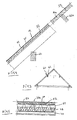
- Fig. 3 indicates a saddle roof 60
- the roof elements according to the FIGS. 1 and 2 may contain. Therefore, in Fig. 4 the lower roof element with the same reference numerals as in Fig. 1 Mistake.
- the roof element 12 is supported on a wooden beam support 62.
- Fig. 5 is a roof element 36a (similar to the Fig. 2 ). It is different from the one after Fig. 2 in that between the concrete plate 46 and the heat-insulating layer 48, a ventilation channel 64 is provided. For the rest, too Fig. 5 the same as to Fig. 2 executed.
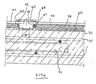
- Fig. 6 is a section indicated by a concrete slab 70, comparable to the concrete slabs according to the preceding figures. At 71 a reinforcement is indicated.
- a conduit 72 extends for a cooling medium.
- solar modules 74, 76 are indicated. They are connected via a very good heat conducting layer 78 and a heat conductive adhesive layer 80 to the outside of the concrete slab 70.
- the adhesive layer 80 is also elastic.
- a groove 82 which is sealed by suitable means.
- This includes a U-shaped rail 84, which is screwed in a suitable manner to the concrete slab 70, as indicated at 86.
- sealing strips 88 are embedded, on which the solar modules 74, 76 are supported near the edge.
- a flat rail 90 extends above the groove 82 and is supported by sealing strips 92 near the edge on the top of the solar modules 74, 76 from. With the help of clamping screws 94, the rails 84, 90 braced against each other to accomplish a seal in the groove area.
Description
Die Erfindung bezieht sich auf ein Dach für Hochbauten nach Anspruch 1.The invention relates to a roof for building construction according to claim 1.
Neben den Wänden sollen die Dächer von Hochbauten, z.B. Hallenbauten eine Vielzahl von Funktionen erfüllen, etwa sommerlicher und winterlicher Wärmeschutz, Wärmespeicherfähigkeit, Brandschutz, Feuchtigkeitsschutz, Winddichtheit, gegebenenfalls Schallschutz usw..Next to the walls, the roofs of buildings, e.g. Hall buildings fulfill a variety of functions, such as summer and winter thermal insulation, heat storage capacity, fire protection, moisture protection, windproofness, possibly sound insulation, etc ..
Aus
Der Erfindung liegt die Aufgabe zugrunde, ein Dach für Hallenbauten zu schaffen, das neben der Erzielung der erwähnten Wirkungen auch für die Gewinnung regenerativer Energie genutzt werden kann. Darüber hinaus soll es industriell auf einfache Weise vorgefertigt und leicht montiert werden können.The invention has for its object to provide a roof for hall buildings, which can be used in addition to the achievement of the aforementioned effects for the production of renewable energy. In addition, it should be industrially prefabricated in a simple manner and easy to install.
Diese Aufgabe wird durch die Merkmale des Anspruchs 1 gelöst.This object is solved by the features of claim 1.
Das erfindungsgemäße Dach besteht vom Aufbau her aus einzelnen nebeneinander liegenden Dachelementen, die jeweils eine Massivplatte aufweisen. Die Massivplatte, aus Beton, soll gute Wärmeleiteigenschaften aufweisen. Die Platte weist nach einer Ausgestaltung der Erfindung mehrere Vorsprünge auf, insbesondere in Form sogenannter Gitterträger, welche einen Unter- und einen Obergurt aufweisen. Bei einschaligem Aufbau der Dachelemente, welcher keinen Teil der Erfindung darstellt, liegt die Platte oben, und die Gitterträger sind mit ihrem Obergurt in die Platte eingebettet, während der Untergurt im Abstand zur Platte über Diagonalstäbe mit dem Obergurt verbunden ist. In die Platten sind Leitungsabschnitte eingebettet, die zusammen eine Verbindungsleitung ergeben zwecks Verbindung z.B. mit einem Wärmeaustauscher einer thermischen Solaranlage, etwa zur Gewinnung von Warmwasser. Zu diesem Zweck kann die Außenseite der Platten mit einer schwarzen Schicht versehen werden, um ein großes Absorptionsvermögen zu gewährleisten. Alternativ bzw. zusätzlich können auf der Außenseite der Platten Solarzellen angeordnet werden zwecks Gewinnung elektrischer Energie. Hochdächer, z.B. Hallendächer weisen zumeist ein relativ geringes Gefälle und eine relativ große Fläche auf, so daß eine große Auffangfläche für Sonneneinstrahlung gegeben ist und damit die Möglichkeit, Energie in großem Umfang zu gewinnen. Besonders vorteilhaft ist naturgemäß ein Dach für Photovoltaik oder Solarthermie, wenn das Dach bzw. die das Dach tragende Tragkonstruktion um eine Hochachse drehbar gestaltet wird, so daß das Dach jeweils optimal zur Sonneneinstrahlung ausgerichtet werden kann.The roof of the invention consists of the structure of individual adjacent roof elements, each having a solid plate. The solid slab, made of concrete, should have good thermal conductivity. The plate has, according to one embodiment of the invention, a plurality of projections, in particular in the form of so-called lattice girders, which have a lower and an upper chord. In einschaligem structure of the roof elements, which does not form part of the invention, the plate is on top, and the lattice girders are with their upper flange in embedded the plate, while the lower flange is connected at a distance to the plate via diagonal bars with the upper flange. In the plates line sections are embedded, which together provide a connection line for the purpose of connection, for example with a heat exchanger of a solar thermal system, such as for the production of hot water. For this purpose, the outside of the plates can be provided with a black layer to a large To ensure absorption capacity. Alternatively or additionally, solar cells can be arranged on the outside of the plates for the purpose of obtaining electrical energy. High roofs, eg hall roofs usually have a relatively low slope and a relatively large area, so that a large collecting area for solar radiation is given and thus the opportunity to gain energy on a large scale. Of particular advantage is of course a roof for photovoltaic or solar thermal, when the roof or the roof supporting support structure is designed to be rotatable about a vertical axis, so that the roof can be optimally aligned to the sunlight.
Bei der Anordnung von Solarzellen auf den Platten, dienen die Leitungsrohre in den Platten dazu, die Solarzellen zu kühlen. Das von den Solarzellen erwärmte Wasser oder eine andere geeignete Flüssigkeit kann einer Nutzung zugeführt werden.When arranging solar cells on the plates, the conduits in the plates serve to cool the solar cells. The heated by the solar cells water or other suitable liquid can be used.
Bei einer Dachlösung, die nicht Teil der Erfindung ist, können die Dachelemente mit einer Platte mehrere nach unten weisende Vorsprünge aufweisen, über welche sich die Platte über eine elastische Schicht an einer Tragkonstruktion abstützen. Die Tragkonstruktion kann beispielsweise von Doppel-T-Trägern oder auch von Holzbalken gebildet sein. Die Vorsprünge können nach einer Ausgestaltung, die nicht Teil der Erfindung ist von Gitterträgern gebildet sein, deren Obergurt in die Platte eingebettet und deren Untergurt im Abstand zum Obergurt über Diagonalstäbe mit dem Obergurt verbunden ist. Alternativ können Träger aus Stahl, Holz oder Stahlbeton verwendet werden.In a roof solution, which is not part of the invention, the roof elements with a plate may have a plurality of downwardly facing projections, via which the plate is supported via an elastic layer on a support structure. The support structure may be formed for example by double T-beams or wooden beams. The projections can be formed by lattice girders according to an embodiment, which is not part of the invention, the top flange embedded in the plate and the bottom chord is connected at a distance to the top flange via diagonal bars with the top flange. Alternatively, beams made of steel, wood or reinforced concrete can be used.
Bei einer anderen Lösung sind die Platten z.B. mit Gitterträgern armiert, wobei jedoch die Abstützung der Dachelemente über die Platten an einer Tragkonstruktion erfolgt, wiederum über eine elastische Schicht. Die erwähnten elastischen Schichten haben die Aufgabe, eine Relativbewegung zwischen den Dachelementen bzw. der aus den Dachelementen gebildeten Dachscheibe relativ zur Tragkonstruktion zuzulassen, beispielsweise bei thermischen Dehnungen usw..In another solution, the plates are reinforced, for example with lattice girders, but the support of the roof elements via the plates takes place on a support structure, again via an elastic layer. The mentioned elastic layers have the task of a relative movement between the roof elements or the allow roof panel formed from the roof elements relative to the supporting structure, for example, in thermal expansion etc ..
Bei der Ausgestaltung der Erfindung ist jeweils eine untere Platte vorgesehen, die sich auf einer Tragkonstruktion abstützt, wiederum vorzugsweise über eine elastische Schicht. Die Platte ist mit nach oben weisenden Vorsprüngen versehen, z.B. Gitterträger oder Träger aus Stahl, Holz oder Stahlbeton, auf die sich eine weitere obere Platte über eine elastische Schicht abstützt. In diesem Falle ist die obere Platte mit Leitungen versehen zwecks Wärmeübertragung auf die in der Leitung fließende Flüssigkeit. Alternativ können Solarzellen auf der Außenseite des Daches montiert werden.In the embodiment of the invention, a lower plate is provided in each case, which is supported on a support structure, again preferably via an elastic layer. The plate is provided with upwardly facing projections, e.g. Lattice girder or girder made of steel, wood or reinforced concrete, on which a further top plate is supported by an elastic layer. In this case, the upper plate is provided with conduits for heat transfer to the liquid flowing in the conduit. Alternatively, solar cells can be mounted on the outside of the roof.
Die Solarzellen können als Module mittels einer gut wärmeleitenden Schicht auf der Außenseite der Platten mit einem wärmeleitenden Kleber verklebt sein. Damit zwischen die Fugen keine Feuchtigkeit eindringt, kann nach einer weiteren Ausgestaltung der Erfindung vorgesehen sein, daß benachbarte Solarzellen bzw. Solarmodule im Bereich der Fugen kantennah auf Dichtungen abgestützt sind, die an Schienen angeordnet sind, die ihrerseits an den Platten befestigt sind. Im Bereich der Fugen sind oberhalb der benachbarten Solarzellen bzw. Module Dichtungsschienen angeordnet, die über Dichtungen beiderseits der Fugen auf den Solarzellen aufliegen. Spannmittel können beide Schienen miteinander verspannen. Auf diese Weise ist eine vollständige Abdichtung im Fugenbereich der Solarmodule gewährleistet.The solar cells can be glued as modules by means of a good heat-conducting layer on the outside of the plates with a thermally conductive adhesive. So that no moisture penetrates between the joints, it can be provided according to a further embodiment of the invention that adjacent solar cells or solar modules are supported near the edges edge seals on seals, which are arranged on rails, which in turn are attached to the plates. In the area of the joints, sealing rails are arranged above the adjacent solar cells or modules, which rest on the solar cells via seals on both sides of the joints. Clamping devices can clamp both rails together. In this way, a complete seal in the joint area of the solar modules is guaranteed.
Anstelle der Aufbringung der Solarmodule oder der solarthermischen Module auf der Außenseite der Platten können diese nach einer weiteren Ausgestaltung der Erfindung in die Platten eingegossen sein. Sie werden daher vor dem Vergießen der Platten in die Schalung eingelegt. Schutzschichten für die Module können zugleich die Dachhaut bilden.Instead of applying the solar modules or the solar thermal modules on the outside of the plates they can be cast according to a further embodiment of the invention in the plates. You will therefore be before shedding the Plates inserted into the formwork. Protective layers for the modules can also form the roof skin.
Bei der Verwendung von Solarmodulen können die Platten Rohrleitungen aufweisen, die ebenfalls in die Platten eingegossen sein können, in denen ein Kühlmedium fließt. Bekanntlich entsteht bei der Aktivität der Solarmodule Wärme, die gegebenenfalls abzuführen ist. Das erwärmte Medium kann seinerseits einer Nutzung zugeführt werden, beispielsweise über einen Wärmeaustauscher zur Erzeugung von Warmwasser.When using solar modules, the plates may have pipelines, which may also be cast in the plates in which a cooling medium flows. As is known, heat is generated during the activity of the solar modules, which may have to be dissipated. The heated medium can in turn be used, for example via a heat exchanger for the production of hot water.
Wenn vornehmend von Massivplatten gesprochen wird, sind damit nicht ausschließlich von spezifischem Gewicht schwere Platten gemeint. Wesentlich ist aber, daß sie eine gute Wärmeleitfähigkeit aufweisen.When speaking of massive plates, it does not mean heavy plates only of specific gravity. It is essential, however, that they have good thermal conductivity.
Ausführungsbeispiele eines erfindungsgemäßen Daches werden anhand von Zeichnungen nachfolgend näher erläutert.
- Fig. 1
- zeigt einen Schnitt durch einen Teil eines Daches, das kein Teil der Erfindung ist.
- Fig. 2
- zeigt einen Schnitt durch einen Teil einer Ausführungsform eines Daches nach der Erfindung.
- Fig. 3
- zeigt schematisch angedeutet ein Solardach.
- Fig. 4
- zeigt zwei Einzelheiten des Daches nach
Fig. 3 . - Fig. 5
- zeigt eine Abwandlung der Einzelheit eines Daches nach
Fig. 2 . - Fig. 6
- zeigt eine andere Ausführungsform eines Teils eines erfindungsgemäßen Solardachs im Schnitt.
- Fig. 1
- shows a section through a part of a roof, which is not part of the invention.
- Fig. 2
- shows a section through a part of an embodiment of a roof according to the invention.
- Fig. 3
- schematically shows a solar roof.
- Fig. 4
- shows two details of the roof
Fig. 3 , - Fig. 5
- shows a modification of the detail of a roof
Fig. 2 , - Fig. 6
- shows another embodiment of a portion of a solar roof according to the invention in section.
In
In die Betonplatte 14 ist ein Obergurt 20 mindestens eines Gitterträgers 22 eingebettet. Der Obergurt 20 ist mit einem Untergurt 24 über Diagonalstäbe 26 verbunden. Auf der durch die Betonplatten 14 gebildeten Dachfläche ist eine Dichtungsschicht 28 aufgelagert und auf dieser sind Solarzellen 30 angeordnet. Anstelle der Solarzellen 30 kann eine dunkle bzw. schwarze Schicht auf die Dichtungsschicht 30 aufgebracht sein. Anstelle von Gitterträgern können Träger aus Stahl, Holz oder Stahlbeton vorgesehen werden.In the
In die Betonplatte 14 ist mindestens ein Leitungsrohr 32 eingelassen. Leitungsrohre 32 benachbarter Dachelemente 10, 12 sind miteinander verbunden und bilden eine zusammenhängende Leitung, die mit einem Wärmetauscher einer thermischen Solaranlage verbunden ist. Letzteres ist nicht dargestellt.In the
In
Unterhalb des Gitterträgers 22 ist eine abgehängte Decke 34 zu erkennen, die am anderen Flansch des Doppel-T-Trägers 18 befestigt ist. Zwischen den Betonplatten 14 und der abgehängten Decke 34 kann Isoliermaterial eingebracht sein.Below the
In
In der Betonplatte 46 befinden sich Solarthermrohre 52. Auf der Dachfläche ist eine Dichtung 54 aufgelegt und auf dieser sind Solarzellen 56 angeordnet. Zwischen den Platten 40, 46 ist thermisches Dämmaterial 48 angeordnet.In the
In der Darstellung nach
In
In
Durch die Betonplatte erstreckt sich eine Leitung 72 für ein Kühlmedium. Auf der Betonplatte 70 sind Solarmodule 74, 76 angedeutet. Sie sind über eine sehr gut wärmeleitende Schicht 78 und eine wärmeleitende Klebschicht 80 mit der Außenseite der Betonplatte 70 verbunden. Die Klebschicht 80 ist darüber hinaus elastisch.Through the concrete slab, a
Zwischen benachbarten Solarmodulen 74, 76 ist eine Nut 82 vorhanden, welche durch geeignete Mittel abgedichtet ist. Hierzu gehört eine U-förmige Schiene 84, die in geeigneter Weise mit der Betonplatte 70 verschraubt ist, wie bei 86 angedeutet. In die freien Schenkel der U-förmigen Schiene 84 sind Dichtungsbänder 88 eingelassen, auf die sich die Solarmodule 74, 76 kantennah abstützen. Eine flache Schiene 90 erstreckt sich oberhalb der Nut 82 und stützt sich über Dichtungsbänder 92 kantennah auf der Oberseite der Solarmodule 74, 76 ab. Mit Hilfe von Spannschrauben 94 werden die Schienen 84, 90 gegeneinander verspannt, um eine Dichtung im Nutbereich zu bewerkstelligen.Between adjacent
Durch die Leitung fließt ein Kühlmittel, durch das eine Kühlung der Solarmodule 74, 76 erfolgt. Der Wirkungsgrad von Solarmodulen ist größer, wenn sie bei relativ niedrigen Temperaturen arbeiten. Dadurch kommt es zu einer Erwärmung des Kühlmediums in den Leitungen 72, welche wiederum in geeigneter Weise ausgenutzt werden kann, beispielsweise um Wasser zu erwärmen.Through the line flows a coolant through which a cooling of the
Claims (11)
- A roof for buildings, with a beam structure and adjacent roof elements (36) each having a concrete plate (46) as the top plate, with a sealing layer (54) on the outer side of the top plates (54), conduction sections (52) embedded into the top plates (54) for connection to a heat exchanger of a solar thermal installation and/or to solar cells that are fixed on the outer side of the plates, wherein the roof elements (36) each have also a bottom plate (38) which is supported on a supporting structure (48), preferably via an elastic layer, characterised in that the bottom plates (38) have upside-pointing projections in the form of a lattice girder, wherein the bottom boom (40) of the lattice girder is embedded into the bottom plate (38) and wherein the top boom (42) of the lattice girder supports the top plate (54) via an elastic layer (44).
- The roof according to claim 1, characterised in that a suspended layer is disposed below the lower boom.
- A roof according to claim 1 or 2, characterised in that a thermal insulation is disposed between the top plate and the bottom plate.
- The roof according to claim 3, characterised in that a rear ventilation channel is provided between the top plate and the insulation.
- The roof according to claim 1, characterised in that the plate has girders made of steel, wood or steel reinforced concrete, by which the top plate is supported via the elastic layer.
- A roof according to any one of claims 1 to 5, characterised in that the solar cells or solar modules, respectively, are glued together by a heat-conducting elastic glue (80) by means of a fairly heat-conducting layer (78) on the outer side of the plates (70).
- A roof according to any one of claims 1 to 6, characterised in that neighbouring solar cells or modules (74, 76), respectively, are supported on seals near to their edges in the region of the joints (82), said seals being disposed on rails (84) which are in turn fastened on the plates (70) and rest on the solar cells or modules (74, 76), respectively, in the region of the joints (82) on both sides of the joints (82) above neighbouring solar cells or modules (74, 76), respectively, and that tensioning means are provided which tension the upper and the lower rails (90, 84) against each other.
- The roof according to claim 7, characterised in that the seals are formed by sealing tapes.
- A roof according to any one of claims 1 to 9, characterised in that solar modules and/or solar thermal modules are cast into the plate.
- The roof according to claim 9, characterised in that protective layers for the cast-in modules form the roof's vapour seal.
- A roof according to claim 9 or 10, characterised in that solar modules are cast into the plates together with pipe modules.
Applications Claiming Priority (1)
| Application Number | Priority Date | Filing Date | Title |
|---|---|---|---|
| DE202007001982U DE202007001982U1 (en) | 2007-02-10 | 2007-02-10 | Roof for buildings, designed to recover solar energy, includes concrete panels with sealing, insulation, framework, embedded pipes and photovoltaic cells |
Publications (3)
| Publication Number | Publication Date |
|---|---|
| EP1988227A2 EP1988227A2 (en) | 2008-11-05 |
| EP1988227A3 EP1988227A3 (en) | 2010-06-09 |
| EP1988227B1 true EP1988227B1 (en) | 2011-10-26 |
Family
ID=38056483
Family Applications (1)
| Application Number | Title | Priority Date | Filing Date |
|---|---|---|---|
| EP08000985A Expired - Fee Related EP1988227B1 (en) | 2007-02-10 | 2008-01-19 | Roof for buildings |
Country Status (2)
| Country | Link |
|---|---|
| EP (1) | EP1988227B1 (en) |
| DE (1) | DE202007001982U1 (en) |
Families Citing this family (6)
| Publication number | Priority date | Publication date | Assignee | Title |
|---|---|---|---|---|
| IT1397125B1 (en) * | 2009-12-01 | 2013-01-04 | Mabo Prefabbricati S P A | MANUFACTURED IN CEMENTITIOUS CONGLOMERATE FOR COVERINGS OF BUILDINGS, PARTICULARLY FOR BUILDINGS WITH LARGE LIGHTS AND ITS REALIZED PROCEDURE. |
| WO2012041330A2 (en) * | 2010-09-30 | 2012-04-05 | Connovate Aps | Roofing elements |
| CN103452220A (en) * | 2012-05-30 | 2013-12-18 | 张跃 | Floor slab with prefabricated water and electric components |
| CN104100051A (en) * | 2014-07-07 | 2014-10-15 | 张跃 | Prefabricated roof |
| US10547270B2 (en) | 2016-02-12 | 2020-01-28 | Solarcity Corporation | Building integrated photovoltaic roofing assemblies and associated systems and methods |
| CN106437001A (en) * | 2016-08-30 | 2017-02-22 | 李予新 | Overall roof panel with cornice |
Family Cites Families (5)
| Publication number | Priority date | Publication date | Assignee | Title |
|---|---|---|---|---|
| DE3229208A1 (en) | 1982-08-05 | 1984-02-09 | Bürkle, Albrecht, Dipl.-Ing., 7012 Fellbach | Heating installation |
| FR2598491A1 (en) | 1986-02-28 | 1987-11-13 | Blazun Georges | Solar water heater for a roof or the like |
| DE19527676A1 (en) * | 1995-07-28 | 1997-01-30 | Loesch Gmbh Betonwerke | Self-supporting building board for erecting a sloping roof |
| DE10000742A1 (en) * | 2000-01-11 | 2001-07-12 | Klaus Schlieckenrieder | Solar absorber for roof mounting consists of self-hardening bearer material, e.g. concrete, plaster or ceramic material, and can be cast into piece with one or more capillary tubes |
| JP3930480B2 (en) * | 2004-01-13 | 2007-06-13 | 株式会社オーエムソーラー協会 | Solar system house heat collecting roof |
-
2007
- 2007-02-10 DE DE202007001982U patent/DE202007001982U1/en not_active Expired - Lifetime
-
2008
- 2008-01-19 EP EP08000985A patent/EP1988227B1/en not_active Expired - Fee Related
Also Published As
| Publication number | Publication date |
|---|---|
| EP1988227A2 (en) | 2008-11-05 |
| EP1988227A3 (en) | 2010-06-09 |
| DE202007001982U1 (en) | 2007-05-10 |
Similar Documents
| Publication | Publication Date | Title |
|---|---|---|
| EP1992017B1 (en) | Fastening device for fastening objects on sealed outer building surfaces | |
| EP1988227B1 (en) | Roof for buildings | |
| WO2012031581A1 (en) | Solar inverted roof | |
| WO2010063811A2 (en) | Installation system | |
| DE202008014320U1 (en) | component | |
| DE202009011109U1 (en) | Flat roof foundation for photovoltaic modules | |
| DE202009001072U1 (en) | Device for mounting solar modules | |
| DE10203338A1 (en) | System of portable solar heating panels has pre-assembled panels which may be interconnected to form larger roof panels | |
| EP2937646B1 (en) | Mounting system for an area heating or cooling system covered by plate-shaped elements | |
| DE202010000227U1 (en) | Arrangement for fastening profile rails for photovoltaic and / or solar panels on flat roofs | |
| DE102009003167A1 (en) | Mounting system for mounting solar modules | |
| DE102007014165A1 (en) | Fastening element, has retaining element on roof, which has base wall part and flexible strip is placed on freely accessible upper side as fastening element, which extends away over facing edge section of base wall part | |
| DE102008062087A1 (en) | Absorber roof for heat pump-heating system, has two battens that are partially formed of hollow profiles via which heat transfer fluid passes, where one of battens is provided for directly holding water-permeable roof covering | |
| DE102006035146A1 (en) | Thermal insulation device for building e.g. house, roof, has roof insulating plate with insulation layer, water-proof cover plate attached to insulating plate, and another insulation layer arranged below former insulation layer | |
| DE102008056556A1 (en) | Mounting arrangement for a rooftop mounting | |
| DE102010009698B4 (en) | Soundproof wall equipped with solar modules | |
| EP0014355A1 (en) | Heat exchanger for regenerating environmental heat | |
| DE2925293C3 (en) | Roofing | |
| EP2556307B1 (en) | Use of a mounting system for flat components on a pitched roof | |
| WO2024037897A1 (en) | Roof structure having photovoltaic modules | |
| DE3011457A1 (en) | Heat recovery system of heat pump type - has pipeline system between layers of flexible, bituminous, sealing material | |
| DE202007007207U1 (en) | Holding element and system for fixing plates on a roof with a corresponding holding element | |
| EP4163452A1 (en) | Pitched roof construction | |
| DE2735108A1 (en) | Solar energy heating panel - has serpentine channels with parabolic surfaces for heat carrying fluid in base under reflective and glass panels | |
| DE19600600C2 (en) | Panel component and roof, ceiling or wall construction, consisting of such panel components |
Legal Events
| Date | Code | Title | Description |
|---|---|---|---|
| PUAI | Public reference made under article 153(3) epc to a published international application that has entered the european phase |
Free format text: ORIGINAL CODE: 0009012 |
|
| AK | Designated contracting states |
Kind code of ref document: A2 Designated state(s): AT BE BG CH CY CZ DE DK EE ES FI FR GB GR HR HU IE IS IT LI LT LU LV MC MT NL NO PL PT RO SE SI SK TR |
|
| AX | Request for extension of the european patent |
Extension state: AL BA MK RS |
|
| PUAL | Search report despatched |
Free format text: ORIGINAL CODE: 0009013 |
|
| AK | Designated contracting states |
Kind code of ref document: A3 Designated state(s): AT BE BG CH CY CZ DE DK EE ES FI FR GB GR HR HU IE IS IT LI LT LU LV MC MT NL NO PL PT RO SE SI SK TR |
|
| AX | Request for extension of the european patent |
Extension state: AL BA MK RS |
|
| 17P | Request for examination filed |
Effective date: 20101209 |
|
| AKX | Designation fees paid |
Designated state(s): DE |
|
| GRAP | Despatch of communication of intention to grant a patent |
Free format text: ORIGINAL CODE: EPIDOSNIGR1 |
|
| RIC1 | Information provided on ipc code assigned before grant |
Ipc: E04B 7/22 20060101AFI20110218BHEP Ipc: H01L 31/048 20060101ALI20110218BHEP |
|
| GRAS | Grant fee paid |
Free format text: ORIGINAL CODE: EPIDOSNIGR3 |
|
| GRAA | (expected) grant |
Free format text: ORIGINAL CODE: 0009210 |
|
| RAP1 | Party data changed (applicant data changed or rights of an application transferred) |
Owner name: MDV DR. MAACK GMBH |
|
| AK | Designated contracting states |
Kind code of ref document: B1 Designated state(s): DE |
|
| REG | Reference to a national code |
Ref country code: DE Ref legal event code: R096 Ref document number: 502008005296 Country of ref document: DE Effective date: 20111229 |
|
| PLBE | No opposition filed within time limit |
Free format text: ORIGINAL CODE: 0009261 |
|
| STAA | Information on the status of an ep patent application or granted ep patent |
Free format text: STATUS: NO OPPOSITION FILED WITHIN TIME LIMIT |
|
| 26N | No opposition filed |
Effective date: 20120727 |
|
| REG | Reference to a national code |
Ref country code: DE Ref legal event code: R097 Ref document number: 502008005296 Country of ref document: DE Effective date: 20120727 |
|
| PGFP | Annual fee paid to national office [announced via postgrant information from national office to epo] |
Ref country code: DE Payment date: 20160331 Year of fee payment: 9 |
|
| REG | Reference to a national code |
Ref country code: DE Ref legal event code: R119 Ref document number: 502008005296 Country of ref document: DE |
|
| PG25 | Lapsed in a contracting state [announced via postgrant information from national office to epo] |
Ref country code: DE Free format text: LAPSE BECAUSE OF NON-PAYMENT OF DUE FEES Effective date: 20170801 |