EP1986263A1 - Système de cellules combustibles et procédé de démarrage correspondant - Google Patents
Système de cellules combustibles et procédé de démarrage correspondant Download PDFInfo
- Publication number
- EP1986263A1 EP1986263A1 EP08153390A EP08153390A EP1986263A1 EP 1986263 A1 EP1986263 A1 EP 1986263A1 EP 08153390 A EP08153390 A EP 08153390A EP 08153390 A EP08153390 A EP 08153390A EP 1986263 A1 EP1986263 A1 EP 1986263A1
- Authority
- EP
- European Patent Office
- Prior art keywords
- fuel cell
- gas
- reformer
- burner
- fuel
- Prior art date
- Legal status (The legal status is an assumption and is not a legal conclusion. Google has not performed a legal analysis and makes no representation as to the accuracy of the status listed.)
- Granted
Links
- 239000000446 fuel Substances 0.000 title claims abstract description 162
- 238000000034 method Methods 0.000 title claims abstract description 22
- 239000007789 gas Substances 0.000 claims abstract description 119
- 239000007800 oxidant agent Substances 0.000 claims abstract description 57
- UFHFLCQGNIYNRP-UHFFFAOYSA-N Hydrogen Chemical compound [H][H] UFHFLCQGNIYNRP-UHFFFAOYSA-N 0.000 claims abstract description 20
- 239000002737 fuel gas Substances 0.000 claims abstract description 18
- QVGXLLKOCUKJST-UHFFFAOYSA-N atomic oxygen Chemical compound [O] QVGXLLKOCUKJST-UHFFFAOYSA-N 0.000 claims abstract description 14
- 239000001301 oxygen Substances 0.000 claims abstract description 14
- 229910052760 oxygen Inorganic materials 0.000 claims abstract description 14
- 239000001257 hydrogen Substances 0.000 claims abstract description 9
- 229910052739 hydrogen Inorganic materials 0.000 claims abstract description 9
- 238000010438 heat treatment Methods 0.000 claims description 16
- 238000002407 reforming Methods 0.000 claims description 9
- MYMOFIZGZYHOMD-UHFFFAOYSA-N Dioxygen Chemical compound O=O MYMOFIZGZYHOMD-UHFFFAOYSA-N 0.000 claims description 7
- 229910001882 dioxygen Inorganic materials 0.000 claims description 7
- 230000001590 oxidative effect Effects 0.000 claims description 7
- 230000001419 dependent effect Effects 0.000 claims description 3
- 239000008141 laxative Substances 0.000 claims 2
- 230000002475 laxative effect Effects 0.000 claims 2
- 230000007423 decrease Effects 0.000 claims 1
- 239000002912 waste gas Substances 0.000 claims 1
- 238000002485 combustion reaction Methods 0.000 abstract description 11
- 239000000567 combustion gas Substances 0.000 abstract 2
- 239000000203 mixture Substances 0.000 description 8
- 239000003792 electrolyte Substances 0.000 description 6
- 230000015572 biosynthetic process Effects 0.000 description 5
- 239000000112 cooling gas Substances 0.000 description 5
- 238000006243 chemical reaction Methods 0.000 description 4
- 238000010276 construction Methods 0.000 description 4
- 239000003344 environmental pollutant Substances 0.000 description 3
- 239000012528 membrane Substances 0.000 description 3
- 230000003647 oxidation Effects 0.000 description 3
- 238000007254 oxidation reaction Methods 0.000 description 3
- 231100000719 pollutant Toxicity 0.000 description 3
- UGFAIRIUMAVXCW-UHFFFAOYSA-N Carbon monoxide Chemical compound [O+]#[C-] UGFAIRIUMAVXCW-UHFFFAOYSA-N 0.000 description 2
- 229910002091 carbon monoxide Inorganic materials 0.000 description 2
- 239000003054 catalyst Substances 0.000 description 2
- 230000005611 electricity Effects 0.000 description 2
- 238000009413 insulation Methods 0.000 description 2
- 239000007788 liquid Substances 0.000 description 2
- VNWKTOKETHGBQD-UHFFFAOYSA-N methane Chemical compound C VNWKTOKETHGBQD-UHFFFAOYSA-N 0.000 description 2
- 206010021143 Hypoxia Diseases 0.000 description 1
- 230000004913 activation Effects 0.000 description 1
- 238000004378 air conditioning Methods 0.000 description 1
- 239000003225 biodiesel Substances 0.000 description 1
- 230000015556 catabolic process Effects 0.000 description 1
- 230000003197 catalytic effect Effects 0.000 description 1
- 239000000919 ceramic Substances 0.000 description 1
- 238000011217 control strategy Methods 0.000 description 1
- 238000001816 cooling Methods 0.000 description 1
- -1 diesel Substances 0.000 description 1
- 230000000694 effects Effects 0.000 description 1
- 238000001704 evaporation Methods 0.000 description 1
- 230000008020 evaporation Effects 0.000 description 1
- 239000003502 gasoline Substances 0.000 description 1
- 125000004435 hydrogen atom Chemical group [H]* 0.000 description 1
- 230000001771 impaired effect Effects 0.000 description 1
- 230000010354 integration Effects 0.000 description 1
- 238000002955 isolation Methods 0.000 description 1
- 239000003345 natural gas Substances 0.000 description 1
- 239000005518 polymer electrolyte Substances 0.000 description 1
- 238000010248 power generation Methods 0.000 description 1
- 238000000746 purification Methods 0.000 description 1
- 238000010079 rubber tapping Methods 0.000 description 1
- 230000007704 transition Effects 0.000 description 1
- 238000011144 upstream manufacturing Methods 0.000 description 1
- 239000002918 waste heat Substances 0.000 description 1
Images
Classifications
-
- H—ELECTRICITY
- H01—ELECTRIC ELEMENTS
- H01M—PROCESSES OR MEANS, e.g. BATTERIES, FOR THE DIRECT CONVERSION OF CHEMICAL ENERGY INTO ELECTRICAL ENERGY
- H01M8/00—Fuel cells; Manufacture thereof
- H01M8/04—Auxiliary arrangements, e.g. for control of pressure or for circulation of fluids
- H01M8/04007—Auxiliary arrangements, e.g. for control of pressure or for circulation of fluids related to heat exchange
- H01M8/04014—Heat exchange using gaseous fluids; Heat exchange by combustion of reactants
- H01M8/04022—Heating by combustion
-
- H—ELECTRICITY
- H01—ELECTRIC ELEMENTS
- H01M—PROCESSES OR MEANS, e.g. BATTERIES, FOR THE DIRECT CONVERSION OF CHEMICAL ENERGY INTO ELECTRICAL ENERGY
- H01M8/00—Fuel cells; Manufacture thereof
- H01M8/04—Auxiliary arrangements, e.g. for control of pressure or for circulation of fluids
- H01M8/04223—Auxiliary arrangements, e.g. for control of pressure or for circulation of fluids during start-up or shut-down; Depolarisation or activation, e.g. purging; Means for short-circuiting defective fuel cells
- H01M8/04268—Heating of fuel cells during the start-up of the fuel cells
-
- H—ELECTRICITY
- H01—ELECTRIC ELEMENTS
- H01M—PROCESSES OR MEANS, e.g. BATTERIES, FOR THE DIRECT CONVERSION OF CHEMICAL ENERGY INTO ELECTRICAL ENERGY
- H01M8/00—Fuel cells; Manufacture thereof
- H01M8/06—Combination of fuel cells with means for production of reactants or for treatment of residues
- H01M8/0606—Combination of fuel cells with means for production of reactants or for treatment of residues with means for production of gaseous reactants
- H01M8/0612—Combination of fuel cells with means for production of reactants or for treatment of residues with means for production of gaseous reactants from carbon-containing material
- H01M8/0618—Reforming processes, e.g. autothermal, partial oxidation or steam reforming
-
- Y—GENERAL TAGGING OF NEW TECHNOLOGICAL DEVELOPMENTS; GENERAL TAGGING OF CROSS-SECTIONAL TECHNOLOGIES SPANNING OVER SEVERAL SECTIONS OF THE IPC; TECHNICAL SUBJECTS COVERED BY FORMER USPC CROSS-REFERENCE ART COLLECTIONS [XRACs] AND DIGESTS
- Y02—TECHNOLOGIES OR APPLICATIONS FOR MITIGATION OR ADAPTATION AGAINST CLIMATE CHANGE
- Y02E—REDUCTION OF GREENHOUSE GAS [GHG] EMISSIONS, RELATED TO ENERGY GENERATION, TRANSMISSION OR DISTRIBUTION
- Y02E60/00—Enabling technologies; Technologies with a potential or indirect contribution to GHG emissions mitigation
- Y02E60/30—Hydrogen technology
- Y02E60/50—Fuel cells
Definitions
- the present invention relates to a fuel cell system, in particular in a motor vehicle, and to a method for starting such a fuel cell system.
- a fuel cell system usually includes at least one fuel cell for generating electric power from an anode gas containing hydrogen gas and a cathode gas containing oxygen gas.
- the fuel cell system can be equipped with at least one reformer which generates a hydrogen-containing fuel gas from a hydrogen-containing fuel and an oxygen-containing oxidizer, which can be supplied as anode gas to the fuel cell.
- Both the fuel cell process for generating the current and the reforming process for generating the fuel gas require a predetermined operating temperature in the fuel cell or in the reformer in order to be sufficiently stable or to run with the desired efficiency.
- the fuel cell and the reformer may have ambient temperature, which is significantly lower than the said operating temperatures. If necessary, the fuel cell system should be available relatively quickly for power generation, wherein the starting, in particular a cold start from the ambient temperature, with the lowest possible values for pollutant emissions and fuel consumption should be realized.
- the present invention addresses the problem of providing an improved embodiment for a fuel cell system or an associated starting method, which in particular makes it possible to start the fuel cell system in a comparatively short time at relatively low values for pollutant emissions and fuel consumption.
- This problem is solved according to the invention by the subject matters of the independent claims.
- Advantageous embodiments are the subject of the dependent claims.
- the invention is based on the general idea of operating the reformer as a burner until it reaches a reformer start temperature, which converts the fuel with the oxidizer.
- a reformer start temperature which converts the fuel with the oxidizer.
- the burner operating state and the reformer operating state differ in particular by the air ratio, ie by the oxygen ratio ⁇ . In the burner operating state there is excess oxygen, ie ⁇ > 1, while in the reformer operating state is an oxygen deficiency, ie ⁇ ⁇ 1.
- the reformer can also be operated below the reformer start temperature as a reformer, but unstable and with significantly poorer efficiency.
- the fuel cell system can have a residual gas burner for burning anode gas which contains hydrogen gas containing oxygen gas during operation of the fuel cell and which has cathode gas containing oxygen gas.
- This residual gas burner can be operated within the start procedure with deactivated fuel cell for burning the anode gas conducted through the fuel cell with the cathode gas passed through the fuel cell.
- the reformer reaches its reforming start temperature by its burner operating state, it is switched to its reformer operating state, so that it generates fuel gas as a reformate.
- the oxidizer supplied to the reformer can be preheated by burner exhaust gas discharged from the residual gas burner. Additionally or alternatively, the cathode gas supplied to the fuel cell are preheated by discharged from the residual gas burner burner exhaust gas, in particular after the burner exhaust gas has preheated the reformer supplied oxidizer.
- the heat generated in the residual gas burner can be used advantageously for rapid heating of the reformer and / or the fuel cell. This is particularly advantageous for the reformer in the reformer state when it has not yet reached its optimum operating temperature.
- a cold oxidizer For the supply of a cold oxidizer can affect comparatively strongly in this transition state of the reformer, the mixture forming process taking place therein and / or the partial oxidation process taking place therein.
- a mixture formation process using a so-called "cold flame” can be severely impaired by the introduction of a cold oxidizer.
- the processes in the reformer can be stabilized significantly, allowing it to heat up faster to its operating temperature.
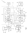
- FIG. 1 shows a highly simplified, schematics-like schematic representation of a fuel cell system.
- Corresponding Fig. 1 comprises a fuel cell system 1, which may preferably be arranged in a motor vehicle, at least one fuel cell 2 and at least one reformer 3.
- the fuel cell 2 serves to generate electric current from an anode gas containing hydrogen gas and a cathode gas containing oxygen. Accordingly, the fuel cell 2 has a cathode side 4 and an anode side 5 which are separated from each other by an electrolyte 6.
- the electrolyte 6 may be a ceramic component and / or a membrane.
- the fuel cell 2 can be designed as a high-temperature fuel cell, in particular as an SOFC fuel cell.
- the fuel cell 2 may be designed as a low-temperature fuel cell, for example as a PEM fuel cell, which operates with a proton transport membrane or with a polymer electrolyte membrane.
- the reformer 3 can then be followed by a CO-gas purification stage, not shown here.
- Via at least one electrical connection 7 is when the fuel cell is activated 2 tapped at this electrical power to supply a basically any consumer 8 with electrical energy.
- the consumer 8 may be formed in a vehicle by one or more electrical consumers of the vehicle; It can also be the entire electrical system of the vehicle.
- the reformer 3 serves to generate a fuel gas containing hydrogen gas from a hydrogen-containing fuel and an oxygen-containing oxidizer.
- the fuel gas is used within the fuel cell system 1 as anode gas for supplying the fuel cell 2.
- an anode gas line 9 connects an output of the reformer 3 to an input of the anode side 5 of the fuel cell 2.
- the reformer 3 contains, for example, a mixture forming section 10 and a downstream fuel gas forming section 11.
- a mixture formation for example in Combination with a complete or partial combustion reaction, which works in particular with cold combustion or cold flame.
- a liquid fuel can be used for mixture formation.
- the fuel is preferably the same fuel with which an internal combustion engine of the vehicle equipped with the fuel cell system 1 is also supplied. Suitable fuels include, for example, gasoline, diesel, biodiesel; Likewise, gaseous fuels such as natural gas are conceivable.
- the actual generation of the fuel gas is effected by a corresponding reaction of the supplied mixture.
- the fuel gas-forming section 11 contains, for this purpose, a catalyst 12 which, with a corresponding oxidizer / fuel ratio, enables a partial oxidation of the fuel, whereby in particular hydrogen gas and carbon monoxide are formed.
- the oxidizer used here is preferably air.
- the fuel cell system 1 shown here includes a residual gas burner 13, which enables combustion of hydrogen gas-containing anode exhaust gas and oxygen gas-containing cathode exhaust gas.
- the conversion of the hydrogen of the anode gas with the oxygen of the cathode gas takes place when the fuel cell 2 is activated within the fuel cell 2 as a function of the power requirement. Even at maximum electrical power of the fuel cell 2, residues of oxygen or hydrogen residues may be contained in the exhaust gases of the fuel cell 2.
- the combustion of the fuel cell exhaust gases in the residual gas burner 3 improves the emission values of the fuel cell system 1 and makes it possible to release the chemically combined heat contained in the fuel cell exhaust gases and to use them to increase the efficiency of the fuel cell system 1.
- the residual gas burner 13 is expediently connected to the cathode side 4 via a cathode exhaust gas line 14 and to the anode side 5 via an anode exhaust gas line 15.
- a cathode gas line 16 is connected to an input of the cathode side 4.
- an oxidizer line 17 is connected to an input of the reformer 3. Since both the cathode gas and the oxidizer are preferably formed by air, a common oxidizer supply 18 may be provided which has a delivery device 19, in particular a pump, a compressor or a blower, and a supply line 20.
- the supply line 20 branches at 21 in the cathode gas line 16 and the oxidizer 17.
- the supply line 20 also branches at 21 into a cooling gas line 22, which is connected to an input, in particular cathode side, of the residual gas burner 13.
- the residual gas burner 13 can be supplied, if necessary, with a cooling gas, which is preferably air.
- a second Oxdator ist 42 is provided, via which the reformer 3 can be supplied with oxidizer additionally or alternatively to the other, the first oxidant line 17.
- corresponding valve means can be provided in order to control the individual oxidizer flows, that is to say in particular the cathode gas, the oxidizer and the cooling gas, with regard to their quantitative distribution.
- the branching point 21 is preferably designed as a valve device, which will also be referred to below as 21.
- This valve device For example, 21 may be configured so as to allow a continuous switching or splitting of the volume flows between the individual branches 16, 17, 22 and 42.
- Oxidator cabinetsen 18 are conceivable, one of which supplies the reformer 3 and the other the fuel cell 2 and the residual gas burner 13 with oxidizing gas or cooling gas.
- a recirculation line 24 branches off at 23, which is connected to an input of the reformer 3 and has a conveyor 25, e.g. a blower, a pump or a compressor.
- a portion of the anode exhaust gas can be supplied to the reformer 3 again. This is advantageous in particular for operating states in which only a reduced amount of hydrogen gas in the anode gas is converted in the fuel cell 2, in particular due to a reduced power requirement.
- a recirculation heat exchanger 26 may be provided, which may be incorporated on the one hand in the recirculation line 24 and on the other hand in the second Oxidatortechnisch 42. This makes it possible to preheat the oxidizer or to cool the recycled anode exhaust gas.
- the recirculation heat exchanger 26 is arranged in the recirculation line 24 upstream of the conveyor 25. Instead of being integrated into the second oxidizer line 42, integration into the cathode gas line 16 may also take place or in the first Oxidatortechnisch 17 or in any other line, such as in the supply line 20 or in the cooling gas line 22 may be provided.
- the fuel cell system 1 presented here also has a reformer heat exchanger 27, which is integrated on the one hand into the first oxidizer line 17 and on the other hand into an exhaust pipe 28 which discharges burner exhaust gas emerging in the residual gas burner 13 from the residual gas burner 13. Accordingly, the reformer heat exchanger 27 enables transfer of heat contained in the burner exhaust gas to the oxidizer to be supplied to the reformer 3.
- the reformer heat exchanger 27 is structurally integrated into an outlet side of the residual gas heat exchanger 13. In principle, however, a separate construction with a spaced arrangement is conceivable.
- the reformer 3 thus comprises a first oxidizer line 17, which leads via the reformer heat exchanger 27, and a second oxidizer line 42, which leads via the recirculation heat exchanger 26, which - depending on the operating state - can be active alternatively or cumulatively.
- the embodiment shown here of the fuel cell system 1 is equipped with a fuel cell heat exchanger 29, which is integrated on the one hand in the cathode gas line 16 and on the other hand in the exhaust pipe 28. This allows heat from the burner exhaust gas to the cathode gas be transferred to preheat this.
- the fuel cell heat exchanger 29 is arranged downstream of the reformer heat exchanger 27 in the exhaust pipe 28.
- the fuel cell heat exchanger 29 is structurally integrated on the output side into the reformer heat exchanger 27. In principle, however, a separate, separate construction is also conceivable here.
- a heating and heat exchanger 30 may be provided, which may be incorporated on the one hand in the exhaust pipe 28 and on the other hand in a heating line 31 and thereby enables a transfer of heat from the burner exhaust gas in a guided in the heating pipe 31 heat transfer medium.
- the heating line 31 can lead to an external with respect to the fuel cell system 1 heat user or heat consumer 32, may in particular belong to a heating circuit 34 and preferably a suitable conveyor 33, such as a pump included.
- the heating circuit 34 may be formed, for example, by a branch of a cooling circuit of an internal combustion engine, which is arranged together with the fuel cell system 1 in a vehicle.
- the heating circuit 34 may be a component of a vehicle air conditioning device which can operate either with a liquid or with a gaseous heat transfer medium.
- the heat consumer 32 is, for example, a corresponding heat exchanger or any other device which is supplied with heat via the heating line 31.
- the fuel cell system 1 is also equipped with a controller 35 which actuates the fuel cell system 1 or its components via corresponding control lines 36.
- the controller 35 serves to actuate the fuel cell 2, the reformer 3 and the residual gas burner 13.
- the controller 35, the conveyor 19 of Oxidator pumps 18, the conveyor 25 of the recirculation line 24 and a conveyor 37, such as a pump, in a fuel line 38 is arranged to supply the reformer 3 with the fuel, operate.
- the controller 35 may be provided for actuating the valve device 21.
- the controller 35 may be connected via signal lines 39 to a sensor, which sensor may in particular comprise a plurality of temperature sensors 40 and / or pressure sensors, not shown, some of which are indicated here by way of example by circles.
- such temperature sensors 40 may be arranged in the reformer 3 at the inlet and at the outlet of the catalytic converter 12. Another temperature sensor 40 is conceivable at the outlet of the residual gas burner 13. Furthermore, a temperature sensor 40 may be provided in the exhaust pipe 28 at the outlet of the reformer heat exchanger 27. In addition, a temperature sensor 40 is arranged in the second oxidizer line 42 for realizing a preferred embodiment. The number and arrangement of the temperature sensors 40 shown is purely exemplary.
- the residual gas burner 13 and the fuel cell 2 form separate and mutually spaced components.
- an embodiment in which the residual gas burner 13 is structurally integrated into an output side of the fuel cell 2 is preferred.
- the fuel cell system 1 can also have a thermally insulating insulation box 41, which is indicated here by a drawn with a broken line frame.
- the isolation box 41 may consist of a single body or of several separate bodies.
- the components which become comparatively hot during operation of the fuel cell system 1 are arranged, while cooler areas are present outside, in which heat-sensitive components can preferably be arranged.
- the fuel cell system 1 operates in particular as follows:
- a cold start of the fuel cell system 1 ie at a start of the fuel cell system 1 in a state in which the individual components of the fuel cell system 1 compared to their usual operating temperature are relatively cold and in particular may have ambient temperature
- a special start procedure is realized, which makes it possible , the fuel cell system 1 in a relatively short time at comparatively low values for fuel consumption and pollutant emissions for the delivery of electricity ready to go.
- the fuel cell 2 is deactivated, that is, the controller 35 does not allow a tapping of electricity to the fuel cell 2.
- the controller 35 does not allow a tapping of electricity to the fuel cell 2.
- no conversion of anode-side hydrogen and cathode-side oxygen and optionally of carbon monoxide takes place within the fuel cell 2.
- Anodic gas and cathode gas can freely flow through the cathode side 4 and the anode side 5 of the fuel cell 2.
- a reformer start temperature is determined, which has been determined, for example, by test series. If the temperature of the reformer 3 is below the reformer start temperature, the reformer 3 is operated for the said start-up procedure in a burner operating state. That is, the reformer 3 is operated as a burner for burning the fuel with the oxidizer.
- the controller 35 controls the supply of the reformer 3 with fuel and with oxidant so that an excess of oxygen prevails, so that the air ratio ⁇ > 1. In this combustion reaction, there is a strong evolution of heat in the reformer 3, whereby it heats up comparatively quickly.
- the controller 35 effects a switchover from the burner operating state to a reforming temperature of the fuel cell 2 reformer operating state. Generated in this reformer operating state the reformer 3 the fuel gas.
- the controller 35 controls this the supply of the reformer 3 with fuel, recycled (recirculated anode (ab) gas) and oxidizer so that in the reformer operating state prevails a fuel surplus, ie an air ratio ⁇ ⁇ 1.
- the reformer operation is exothermic, so that the reformer 3 continues to heat up.
- the hot fuel gas acts on the fuel cell 2, as a result of which it too can continue to heat up.
- the reformer start temperature is lower than the fuel cell start temperature.
- the reformer start temperature is also less than a critical electrolyte temperature, which is present when a contacting of the electrolyte 6 with oxygen would lead to damage of the electrolyte 6.
- This critical electrolyte temperature may be less than or equal to the fuel cell start temperature.
- Below the fuel cell start temperature the fuel cell 2 remains in the deactivated state, even if the reformer 3 exceeds its reforming start temperature and is accordingly operated in the reformer operating state.
- the anode gas thus formed is freely and without implementation - only as a low heat flow - passed through the fuel cell 2 and thus enters the residual gas burner 13.
- the residual gas burner thirteenth combustion of the anode gas or anode exhaust gas with the cathode gas or cathode exhaust gas takes place, which leads to very hot burner exhaust gases.
- the heat can the burner exhaust gas in the reformer heat exchanger 27 for heating the oxidizer and in the Fuel cell heat exchanger 29 for heating the cathode gas are at least partially withdrawn.
- the heated oxidizer stabilizes the reforming process, ie in particular the evaporation of the fuel and mixture formation by means of a cold flame and the partial oxidation.
- the heated oxidizer contributes to the temperature increase of the reformer 3.
- the heated cathode gas also accelerates the heating of the fuel cell 2. As soon as the fuel cell reaches its fuel cell start temperature, it is activated by the controller 35, so that current can be tapped off.
- the reformer heat exchanger 27 is preferably used for the start-up operation of the fuel cell system 1 to heat the oxidizer gas to be supplied to the reformer 3, while in the normal or nominal operation of the system 1 preferably the recirculation heat exchanger 26 is used to cool the recirculated anode exhaust gas.
- the controller 35 operates according to a temperature control strategy, for which purpose it accesses, for example, the temperature sensor 40 arranged in the second oxidizer line 42.
- the oxidizer supply of the reformer 3 takes place predominantly, but as a rule not exclusively via the first oxidizer line 17, ie via the reformer heat exchanger 17.
- the reformer 3 can be operated at full load or under nominal operating conditions.
- the oxidant flow through the first oxidizer line 17, preferably continuously, is reduced, and at the same time the oxidant flow through the second oxidizer line 42 is correspondingly increased.
- the oxidator supply of the reformer 3 takes place predominantly, but generally not exclusively via the second oxidizer line 42, ie via the recirculation heat exchanger 26. This breakdown of the oxidizer flow also takes place during a warm start of the fuel cell 2.
Applications Claiming Priority (1)
| Application Number | Priority Date | Filing Date | Title |
|---|---|---|---|
| DE102007019359A DE102007019359A1 (de) | 2007-04-23 | 2007-04-23 | Brennstoffzellensystem und zugehöriges Startverfahren |
Publications (2)
| Publication Number | Publication Date |
|---|---|
| EP1986263A1 true EP1986263A1 (fr) | 2008-10-29 |
| EP1986263B1 EP1986263B1 (fr) | 2010-06-02 |
Family
ID=39619133
Family Applications (1)
| Application Number | Title | Priority Date | Filing Date |
|---|---|---|---|
| EP08153390A Active EP1986263B1 (fr) | 2007-04-23 | 2008-03-27 | Système de cellules combustibles et procédé de démarrage correspondant |
Country Status (3)
| Country | Link |
|---|---|
| EP (1) | EP1986263B1 (fr) |
| AT (1) | ATE470247T1 (fr) |
| DE (2) | DE102007019359A1 (fr) |
Cited By (3)
| Publication number | Priority date | Publication date | Assignee | Title |
|---|---|---|---|---|
| EP2424020A1 (fr) * | 2009-04-24 | 2012-02-29 | Kyocera Corporation | Dispositif de pile à combustible |
| DE102011006469A1 (de) * | 2011-03-31 | 2012-10-04 | J. Eberspächer GmbH & Co. KG | Brennstoffzellensystem und zugehöriges Betriebsverfahren |
| CN113540525A (zh) * | 2021-07-15 | 2021-10-22 | 山东大学 | 一种固体氧化物燃料电池系统热部件测试装置和方法 |
Families Citing this family (3)
| Publication number | Priority date | Publication date | Assignee | Title |
|---|---|---|---|---|
| DE102009006159A1 (de) | 2009-01-26 | 2010-07-29 | Staxera Gmbh | Steuerung/Regelung einer Temperatur einer Brennstoffzelle |
| DE102010001011A1 (de) * | 2010-01-19 | 2011-07-21 | Robert Bosch GmbH, 70469 | Verfahren zum Betrieb einer Kraft-Wärme-Kopplungsanlage |
| DE102013204023B4 (de) * | 2013-03-08 | 2021-10-07 | Eberspächer Climate Control Systems GmbH & Co. KG | Brennstoffzellensystem |
Citations (4)
| Publication number | Priority date | Publication date | Assignee | Title |
|---|---|---|---|---|
| WO2003021696A2 (fr) * | 2001-09-02 | 2003-03-13 | Webasto Thermosysteme Gmbh | Systeme de production d'energie electrique et son mode de fonctionnement |
| EP1571725A1 (fr) * | 2004-03-04 | 2005-09-07 | Delphi Technologies, Inc. | Générateur électric hybride combinant une pile à combustibleet une turbine à gaz |
| DE102005030474A1 (de) * | 2005-06-28 | 2007-01-04 | J. Eberspächer GmbH & Co. KG | Brennstoffzellensystem für ein Fahrzeug |
| WO2007137068A1 (fr) * | 2006-05-16 | 2007-11-29 | Acumentrics Corporation | Système de pile à combustible et son procédé de fonctionnement |
Family Cites Families (5)
| Publication number | Priority date | Publication date | Assignee | Title |
|---|---|---|---|---|
| DE19755814C1 (de) * | 1997-12-16 | 1999-11-18 | Dbb Fuel Cell Engines Gmbh | Verfahren zum Betrieb einer Anlage zur Wasserdampfreformierung eines Kohlenwasserstoffs |
| US6521204B1 (en) * | 2000-07-27 | 2003-02-18 | General Motors Corporation | Method for operating a combination partial oxidation and steam reforming fuel processor |
| DE10235430A1 (de) * | 2002-08-02 | 2004-02-19 | Truma Gerätetechnik GmbH & Co. | Reformer-Brennstoffzellen-System und Verfahren zum Abschalten und Starten desselben |
| US7261749B2 (en) * | 2002-09-05 | 2007-08-28 | General Motors Corporation | Multi-port autothermal reformer |
| DE102004001310A1 (de) * | 2004-01-07 | 2005-08-11 | Viessmann Werke Gmbh & Co Kg | Verfahren zum Betrieb einer Anlage zur Wasserdampfreformierung eines Kohlenwasserstoffgases |
-
2007
- 2007-04-23 DE DE102007019359A patent/DE102007019359A1/de not_active Withdrawn
-
2008
- 2008-03-27 AT AT08153390T patent/ATE470247T1/de active
- 2008-03-27 DE DE502008000729T patent/DE502008000729D1/de active Active
- 2008-03-27 EP EP08153390A patent/EP1986263B1/fr active Active
Patent Citations (4)
| Publication number | Priority date | Publication date | Assignee | Title |
|---|---|---|---|---|
| WO2003021696A2 (fr) * | 2001-09-02 | 2003-03-13 | Webasto Thermosysteme Gmbh | Systeme de production d'energie electrique et son mode de fonctionnement |
| EP1571725A1 (fr) * | 2004-03-04 | 2005-09-07 | Delphi Technologies, Inc. | Générateur électric hybride combinant une pile à combustibleet une turbine à gaz |
| DE102005030474A1 (de) * | 2005-06-28 | 2007-01-04 | J. Eberspächer GmbH & Co. KG | Brennstoffzellensystem für ein Fahrzeug |
| WO2007137068A1 (fr) * | 2006-05-16 | 2007-11-29 | Acumentrics Corporation | Système de pile à combustible et son procédé de fonctionnement |
Cited By (7)
| Publication number | Priority date | Publication date | Assignee | Title |
|---|---|---|---|---|
| EP2424020A1 (fr) * | 2009-04-24 | 2012-02-29 | Kyocera Corporation | Dispositif de pile à combustible |
| EP2424020A4 (fr) * | 2009-04-24 | 2014-11-19 | Kyocera Corp | Dispositif de pile à combustible |
| US9219283B2 (en) | 2009-04-24 | 2015-12-22 | Kyocera Corporation | Method for controlling fuel cell device during power generation start by controlling power conditioner |
| DE102011006469A1 (de) * | 2011-03-31 | 2012-10-04 | J. Eberspächer GmbH & Co. KG | Brennstoffzellensystem und zugehöriges Betriebsverfahren |
| DE102011006469B4 (de) * | 2011-03-31 | 2017-08-03 | Eberspächer Climate Control Systems GmbH & Co. KG | Brennstoffzellensystem und zugehöriges Betriebsverfahren |
| CN113540525A (zh) * | 2021-07-15 | 2021-10-22 | 山东大学 | 一种固体氧化物燃料电池系统热部件测试装置和方法 |
| CN113540525B (zh) * | 2021-07-15 | 2022-09-23 | 山东大学 | 一种固体氧化物燃料电池系统热部件测试装置和方法 |
Also Published As
| Publication number | Publication date |
|---|---|
| DE502008000729D1 (de) | 2010-07-15 |
| DE102007019359A1 (de) | 2008-10-30 |
| EP1986263B1 (fr) | 2010-06-02 |
| ATE470247T1 (de) | 2010-06-15 |
Similar Documents
| Publication | Publication Date | Title |
|---|---|---|
| EP1679757B1 (fr) | Système de pile à combustible | |
| DE10306234B4 (de) | Verfahren zur Luftversorgung einer Brennstoffzelle und Vorrichtung zur Durchführung des Verfahrens | |
| EP2153485B1 (fr) | Système de pile à combustible fonctionnant avec du gaz liquide | |
| EP1986263B1 (fr) | Système de cellules combustibles et procédé de démarrage correspondant | |
| DE102008018152B4 (de) | Brennstoffzellensystem und zugehöriges Betriebsverfahren | |
| DE10142578A1 (de) | System zum Erzeugen elektrischer Energie und Verfahren zum Betreiben eines Systems zum Erzeugen elektrischer Energie | |
| EP1947723B1 (fr) | Système d'approvisionnement d'énergie | |
| DE102012220082B4 (de) | Fahrzeugbrennstoffzellensystem und zugehöriges Betriebsverfahren | |
| EP1657771B1 (fr) | Système de pile à combustible pour produire de l'éléctricité dans une véhicule avec moteur à combustion interne | |
| EP1228999A2 (fr) | Système de génération de gaz pour un système de pile à combustible et procédé de fonctionnement d'un système de génération de gaz | |
| DE102014115096B4 (de) | System zur versorgung eines fahrzeugs mit elektrischer energie | |
| DE19943690C2 (de) | Brennstoffzellensystem zum Betreiben einer elektrischen Maschine und Verfahren zum Starten eines Brennstoffzellensystems | |
| EP2028709A1 (fr) | Système de pile à combustible | |
| DE102007033150B4 (de) | Betriebsverfahren für ein Brennstoffzellensystem | |
| DE10257212A1 (de) | Brennstoffzellensystem und Verfahren zum Betreiben eines Brennstoffzellensystems | |
| EP1905510B1 (fr) | Système de piles à combustible et son procédé de fonctionnement | |
| DE102008008907A1 (de) | Brennstoffzellensystem | |
| EP1925790B1 (fr) | Système de moteur à combustion interne | |
| EP2075226B1 (fr) | Réformateur, cellules de combustible et procédé de fonctionnement correspondant | |
| EP1845577B1 (fr) | Système de pile à combustible | |
| EP2075225B1 (fr) | Dispositif de reformage, système de piles à combustibles et procédé d'opération du système | |
| DE102007033151B4 (de) | Betriebsverfahren für ein Brennstoffzellensystem | |
| DE102019206701A1 (de) | Brennstoffzellenvorrichtung, sowie Verfahren zum Betreiben einer solchen Brennstoffzellenvorrichtung | |
| EP1986262B1 (fr) | Procédé de calibrage pour une commande de pile à combustible | |
| WO2001091217A1 (fr) | Installation a pile a combustible, comprenant un reformeur |
Legal Events
| Date | Code | Title | Description |
|---|---|---|---|
| PUAI | Public reference made under article 153(3) epc to a published international application that has entered the european phase |
Free format text: ORIGINAL CODE: 0009012 |
|
| AK | Designated contracting states |
Kind code of ref document: A1 Designated state(s): AT BE BG CH CY CZ DE DK EE ES FI FR GB GR HR HU IE IS IT LI LT LU LV MC MT NL NO PL PT RO SE SI SK TR |
|
| AX | Request for extension of the european patent |
Extension state: AL BA MK RS |
|
| 17P | Request for examination filed |
Effective date: 20090429 |
|
| AKX | Designation fees paid |
Designated state(s): AT BE BG CH CY CZ DE DK EE ES FI FR GB GR HR HU IE IS IT LI LT LU LV MC MT NL NO PL PT RO SE SI SK TR |
|
| GRAP | Despatch of communication of intention to grant a patent |
Free format text: ORIGINAL CODE: EPIDOSNIGR1 |
|
| GRAS | Grant fee paid |
Free format text: ORIGINAL CODE: EPIDOSNIGR3 |
|
| GRAA | (expected) grant |
Free format text: ORIGINAL CODE: 0009210 |
|
| AK | Designated contracting states |
Kind code of ref document: B1 Designated state(s): AT BE BG CH CY CZ DE DK EE ES FI FR GB GR HR HU IE IS IT LI LT LU LV MC MT NL NO PL PT RO SE SI SK TR |
|
| REG | Reference to a national code |
Ref country code: GB Ref legal event code: FG4D Free format text: NOT ENGLISH |
|
| REG | Reference to a national code |
Ref country code: CH Ref legal event code: EP |
|
| REG | Reference to a national code |
Ref country code: IE Ref legal event code: FG4D Free format text: LANGUAGE OF EP DOCUMENT: GERMAN |
|
| REF | Corresponds to: |
Ref document number: 502008000729 Country of ref document: DE Date of ref document: 20100715 Kind code of ref document: P |
|
| REG | Reference to a national code |
Ref country code: NL Ref legal event code: T3 |
|
| REG | Reference to a national code |
Ref country code: SE Ref legal event code: TRGR |
|
| PG25 | Lapsed in a contracting state [announced via postgrant information from national office to epo] |
Ref country code: NO Free format text: LAPSE BECAUSE OF FAILURE TO SUBMIT A TRANSLATION OF THE DESCRIPTION OR TO PAY THE FEE WITHIN THE PRESCRIBED TIME-LIMIT Effective date: 20100902 Ref country code: LT Free format text: LAPSE BECAUSE OF FAILURE TO SUBMIT A TRANSLATION OF THE DESCRIPTION OR TO PAY THE FEE WITHIN THE PRESCRIBED TIME-LIMIT Effective date: 20100602 |
|
| LTIE | Lt: invalidation of european patent or patent extension |
Effective date: 20100602 |
|
| PG25 | Lapsed in a contracting state [announced via postgrant information from national office to epo] |
Ref country code: FI Free format text: LAPSE BECAUSE OF FAILURE TO SUBMIT A TRANSLATION OF THE DESCRIPTION OR TO PAY THE FEE WITHIN THE PRESCRIBED TIME-LIMIT Effective date: 20100602 Ref country code: SI Free format text: LAPSE BECAUSE OF FAILURE TO SUBMIT A TRANSLATION OF THE DESCRIPTION OR TO PAY THE FEE WITHIN THE PRESCRIBED TIME-LIMIT Effective date: 20100602 Ref country code: LV Free format text: LAPSE BECAUSE OF FAILURE TO SUBMIT A TRANSLATION OF THE DESCRIPTION OR TO PAY THE FEE WITHIN THE PRESCRIBED TIME-LIMIT Effective date: 20100602 Ref country code: HR Free format text: LAPSE BECAUSE OF FAILURE TO SUBMIT A TRANSLATION OF THE DESCRIPTION OR TO PAY THE FEE WITHIN THE PRESCRIBED TIME-LIMIT Effective date: 20100602 |
|
| PG25 | Lapsed in a contracting state [announced via postgrant information from national office to epo] |
Ref country code: PL Free format text: LAPSE BECAUSE OF FAILURE TO SUBMIT A TRANSLATION OF THE DESCRIPTION OR TO PAY THE FEE WITHIN THE PRESCRIBED TIME-LIMIT Effective date: 20100602 Ref country code: CY Free format text: LAPSE BECAUSE OF FAILURE TO SUBMIT A TRANSLATION OF THE DESCRIPTION OR TO PAY THE FEE WITHIN THE PRESCRIBED TIME-LIMIT Effective date: 20100602 |
|
| REG | Reference to a national code |
Ref country code: IE Ref legal event code: FD4D |
|
| PG25 | Lapsed in a contracting state [announced via postgrant information from national office to epo] |
Ref country code: EE Free format text: LAPSE BECAUSE OF FAILURE TO SUBMIT A TRANSLATION OF THE DESCRIPTION OR TO PAY THE FEE WITHIN THE PRESCRIBED TIME-LIMIT Effective date: 20100602 Ref country code: IE Free format text: LAPSE BECAUSE OF FAILURE TO SUBMIT A TRANSLATION OF THE DESCRIPTION OR TO PAY THE FEE WITHIN THE PRESCRIBED TIME-LIMIT Effective date: 20100602 |
|
| PG25 | Lapsed in a contracting state [announced via postgrant information from national office to epo] |
Ref country code: IS Free format text: LAPSE BECAUSE OF FAILURE TO SUBMIT A TRANSLATION OF THE DESCRIPTION OR TO PAY THE FEE WITHIN THE PRESCRIBED TIME-LIMIT Effective date: 20101002 Ref country code: CZ Free format text: LAPSE BECAUSE OF FAILURE TO SUBMIT A TRANSLATION OF THE DESCRIPTION OR TO PAY THE FEE WITHIN THE PRESCRIBED TIME-LIMIT Effective date: 20100602 Ref country code: RO Free format text: LAPSE BECAUSE OF FAILURE TO SUBMIT A TRANSLATION OF THE DESCRIPTION OR TO PAY THE FEE WITHIN THE PRESCRIBED TIME-LIMIT Effective date: 20100602 Ref country code: SK Free format text: LAPSE BECAUSE OF FAILURE TO SUBMIT A TRANSLATION OF THE DESCRIPTION OR TO PAY THE FEE WITHIN THE PRESCRIBED TIME-LIMIT Effective date: 20100602 |
|
| PG25 | Lapsed in a contracting state [announced via postgrant information from national office to epo] |
Ref country code: IT Free format text: LAPSE BECAUSE OF FAILURE TO SUBMIT A TRANSLATION OF THE DESCRIPTION OR TO PAY THE FEE WITHIN THE PRESCRIBED TIME-LIMIT Effective date: 20100602 |
|
| PLBE | No opposition filed within time limit |
Free format text: ORIGINAL CODE: 0009261 |
|
| STAA | Information on the status of an ep patent application or granted ep patent |
Free format text: STATUS: NO OPPOSITION FILED WITHIN TIME LIMIT |
|
| PG25 | Lapsed in a contracting state [announced via postgrant information from national office to epo] |
Ref country code: DK Free format text: LAPSE BECAUSE OF FAILURE TO SUBMIT A TRANSLATION OF THE DESCRIPTION OR TO PAY THE FEE WITHIN THE PRESCRIBED TIME-LIMIT Effective date: 20100602 |
|
| 26N | No opposition filed |
Effective date: 20110303 |
|
| PG25 | Lapsed in a contracting state [announced via postgrant information from national office to epo] |
Ref country code: GR Free format text: LAPSE BECAUSE OF FAILURE TO SUBMIT A TRANSLATION OF THE DESCRIPTION OR TO PAY THE FEE WITHIN THE PRESCRIBED TIME-LIMIT Effective date: 20100903 |
|
| REG | Reference to a national code |
Ref country code: DE Ref legal event code: R097 Ref document number: 502008000729 Country of ref document: DE Effective date: 20110302 |
|
| BERE | Be: lapsed |
Owner name: J. EBERSPACHER G.M.B.H. & CO. KG Effective date: 20110331 |
|
| REG | Reference to a national code |
Ref country code: NL Ref legal event code: V1 Effective date: 20111001 |
|
| PG25 | Lapsed in a contracting state [announced via postgrant information from national office to epo] |
Ref country code: MC Free format text: LAPSE BECAUSE OF NON-PAYMENT OF DUE FEES Effective date: 20110331 |
|
| REG | Reference to a national code |
Ref country code: FR Ref legal event code: ST Effective date: 20111130 |
|
| PG25 | Lapsed in a contracting state [announced via postgrant information from national office to epo] |
Ref country code: MT Free format text: LAPSE BECAUSE OF FAILURE TO SUBMIT A TRANSLATION OF THE DESCRIPTION OR TO PAY THE FEE WITHIN THE PRESCRIBED TIME-LIMIT Effective date: 20100602 Ref country code: BE Free format text: LAPSE BECAUSE OF NON-PAYMENT OF DUE FEES Effective date: 20110331 |
|
| PG25 | Lapsed in a contracting state [announced via postgrant information from national office to epo] |
Ref country code: FR Free format text: LAPSE BECAUSE OF NON-PAYMENT OF DUE FEES Effective date: 20110331 Ref country code: NL Free format text: LAPSE BECAUSE OF NON-PAYMENT OF DUE FEES Effective date: 20111001 |
|
| REG | Reference to a national code |
Ref country code: CH Ref legal event code: PL |
|
| PG25 | Lapsed in a contracting state [announced via postgrant information from national office to epo] |
Ref country code: LI Free format text: LAPSE BECAUSE OF NON-PAYMENT OF DUE FEES Effective date: 20120331 Ref country code: CH Free format text: LAPSE BECAUSE OF NON-PAYMENT OF DUE FEES Effective date: 20120331 |
|
| PG25 | Lapsed in a contracting state [announced via postgrant information from national office to epo] |
Ref country code: LU Free format text: LAPSE BECAUSE OF NON-PAYMENT OF DUE FEES Effective date: 20110327 |
|
| PG25 | Lapsed in a contracting state [announced via postgrant information from national office to epo] |
Ref country code: PT Free format text: LAPSE BECAUSE OF NON-PAYMENT OF DUE FEES Effective date: 20100602 |
|
| PG25 | Lapsed in a contracting state [announced via postgrant information from national office to epo] |
Ref country code: BG Free format text: LAPSE BECAUSE OF FAILURE TO SUBMIT A TRANSLATION OF THE DESCRIPTION OR TO PAY THE FEE WITHIN THE PRESCRIBED TIME-LIMIT Effective date: 20100902 Ref country code: TR Free format text: LAPSE BECAUSE OF FAILURE TO SUBMIT A TRANSLATION OF THE DESCRIPTION OR TO PAY THE FEE WITHIN THE PRESCRIBED TIME-LIMIT Effective date: 20100602 |
|
| PG25 | Lapsed in a contracting state [announced via postgrant information from national office to epo] |
Ref country code: HU Free format text: LAPSE BECAUSE OF FAILURE TO SUBMIT A TRANSLATION OF THE DESCRIPTION OR TO PAY THE FEE WITHIN THE PRESCRIBED TIME-LIMIT Effective date: 20100602 Ref country code: ES Free format text: LAPSE BECAUSE OF FAILURE TO SUBMIT A TRANSLATION OF THE DESCRIPTION OR TO PAY THE FEE WITHIN THE PRESCRIBED TIME-LIMIT Effective date: 20100913 |
|
| REG | Reference to a national code |
Ref country code: FR Ref legal event code: CD Owner name: EBERSPACHER CLIMATE CONTROL SYSTEMS GMBH & CO. KG Effective date: 20131129 |
|
| REG | Reference to a national code |
Ref country code: DE Ref legal event code: R082 Ref document number: 502008000729 Country of ref document: DE Representative=s name: BRP RENAUD UND PARTNER MBB RECHTSANWAELTE PATE, DE Effective date: 20131212 Ref country code: DE Ref legal event code: R082 Ref document number: 502008000729 Country of ref document: DE Representative=s name: BRP RENAUD UND PARTNER MBB, DE Effective date: 20131212 Ref country code: DE Ref legal event code: R082 Ref document number: 502008000729 Country of ref document: DE Representative=s name: BRP RENAUD & PARTNER, DE Effective date: 20131212 Ref country code: DE Ref legal event code: R081 Ref document number: 502008000729 Country of ref document: DE Owner name: EBERSPAECHER CLIMATE CONTROL SYSTEMS GMBH & CO, DE Free format text: FORMER OWNER: J. EBERSPAECHER GMBH & CO. KG, 73730 ESSLINGEN, DE Effective date: 20131212 |
|
| REG | Reference to a national code |
Ref country code: FR Ref legal event code: TP Owner name: EBERSPACHER EXHAUST TECHNOLOGY GMBH & CO. KG, DE Effective date: 20140204 |
|
| REG | Reference to a national code |
Ref country code: AT Ref legal event code: MM01 Ref document number: 470247 Country of ref document: AT Kind code of ref document: T Effective date: 20130327 |
|
| PG25 | Lapsed in a contracting state [announced via postgrant information from national office to epo] |
Ref country code: AT Free format text: LAPSE BECAUSE OF NON-PAYMENT OF DUE FEES Effective date: 20130327 |
|
| REG | Reference to a national code |
Ref country code: FR Ref legal event code: TP Owner name: EBERSPACHER CLIMATE CONTROL SYSTEMS GMBH & CO., DE Effective date: 20150416 |
|
| PGFP | Annual fee paid to national office [announced via postgrant information from national office to epo] |
Ref country code: SE Payment date: 20230315 Year of fee payment: 16 Ref country code: GB Payment date: 20230323 Year of fee payment: 16 |
|
| PGFP | Annual fee paid to national office [announced via postgrant information from national office to epo] |
Ref country code: DE Payment date: 20240331 Year of fee payment: 17 |