EP1986212A2 - Auslöseranzeigeglied und Abgrenzung und elektrische Schaltvorrichtung mit mehreren Auslöseranzeigegliedern - Google Patents
Auslöseranzeigeglied und Abgrenzung und elektrische Schaltvorrichtung mit mehreren Auslöseranzeigegliedern Download PDFInfo
- Publication number
- EP1986212A2 EP1986212A2 EP08007839A EP08007839A EP1986212A2 EP 1986212 A2 EP1986212 A2 EP 1986212A2 EP 08007839 A EP08007839 A EP 08007839A EP 08007839 A EP08007839 A EP 08007839A EP 1986212 A2 EP1986212 A2 EP 1986212A2
- Authority
- EP
- European Patent Office
- Prior art keywords
- limiter
- indicator
- current
- terminals
- plunger
- Prior art date
- Legal status (The legal status is an assumption and is not a legal conclusion. Google has not performed a legal analysis and makes no representation as to the accuracy of the status listed.)
- Granted
Links
- 239000004020 conductor Substances 0.000 claims description 16
- 230000007246 mechanism Effects 0.000 claims description 5
- 230000004044 response Effects 0.000 claims description 4
- 230000006872 improvement Effects 0.000 description 2
- 239000000463 material Substances 0.000 description 2
- 238000010791 quenching Methods 0.000 description 2
- 241000499489 Castor canadensis Species 0.000 description 1
- 235000011779 Menyanthes trifoliata Nutrition 0.000 description 1
- 230000015572 biosynthetic process Effects 0.000 description 1
- 229920001940 conductive polymer Polymers 0.000 description 1
- 230000006378 damage Effects 0.000 description 1
- 238000010438 heat treatment Methods 0.000 description 1
- 239000000155 melt Substances 0.000 description 1
- 239000002184 metal Substances 0.000 description 1
- 230000004048 modification Effects 0.000 description 1
- 238000012986 modification Methods 0.000 description 1
- 230000002441 reversible effect Effects 0.000 description 1
- 230000003685 thermal hair damage Effects 0.000 description 1
- 230000007704 transition Effects 0.000 description 1
Images



Classifications
-
- H—ELECTRICITY
- H01—ELECTRIC ELEMENTS
- H01H—ELECTRIC SWITCHES; RELAYS; SELECTORS; EMERGENCY PROTECTIVE DEVICES
- H01H85/00—Protective devices in which the current flows through a part of fusible material and this current is interrupted by displacement of the fusible material when this current becomes excessive
- H01H85/02—Details
- H01H85/30—Means for indicating condition of fuse structurally associated with the fuse
- H01H85/303—Movable indicating elements
-
- H—ELECTRICITY
- H01—ELECTRIC ELEMENTS
- H01H—ELECTRIC SWITCHES; RELAYS; SELECTORS; EMERGENCY PROTECTIVE DEVICES
- H01H85/00—Protective devices in which the current flows through a part of fusible material and this current is interrupted by displacement of the fusible material when this current becomes excessive
- H01H85/02—Details
- H01H85/20—Bases for supporting the fuse; Separate parts thereof
-
- H—ELECTRICITY
- H01—ELECTRIC ELEMENTS
- H01H—ELECTRIC SWITCHES; RELAYS; SELECTORS; EMERGENCY PROTECTIVE DEVICES
- H01H9/00—Details of switching devices, not covered by groups H01H1/00 - H01H7/00
- H01H9/10—Adaptation for built-in fuses
-
- H—ELECTRICITY
- H01—ELECTRIC ELEMENTS
- H01H—ELECTRIC SWITCHES; RELAYS; SELECTORS; EMERGENCY PROTECTIVE DEVICES
- H01H85/00—Protective devices in which the current flows through a part of fusible material and this current is interrupted by displacement of the fusible material when this current becomes excessive
- H01H85/02—Details
- H01H2085/0233—Details with common casing for fusible elements inserted in more than one phase or more than one circuit
-
- H—ELECTRICITY
- H01—ELECTRIC ELEMENTS
- H01H—ELECTRIC SWITCHES; RELAYS; SELECTORS; EMERGENCY PROTECTIVE DEVICES
- H01H85/00—Protective devices in which the current flows through a part of fusible material and this current is interrupted by displacement of the fusible material when this current becomes excessive
- H01H85/02—Details
- H01H85/20—Bases for supporting the fuse; Separate parts thereof
- H01H2085/2095—Triangular setup of fuses, e.g. for space saving
-
- H—ELECTRICITY
- H01—ELECTRIC ELEMENTS
- H01H—ELECTRIC SWITCHES; RELAYS; SELECTORS; EMERGENCY PROTECTIVE DEVICES
- H01H89/00—Combinations of two or more different basic types of electric switches, relays, selectors and emergency protective devices, not covered by any single one of the other main groups of this subclass
Definitions
- the invention pertains generally to electrical switching apparatus and, more particularly, to circuit breakers including a limiter having plural trip indicator members.
- the invention also relates to limiters and to trip indicators therefor.
- Current limiters employ a current interruption device that rapidly and effectively brings the current to a relatively low or zero value upon the occurrence of a line fault or overload condition.
- Circuit protection devices protect electrical equipment from damage when excess current flows in a power circuit due to overload or short circuit conditions. Such devices have a relatively low resistivity and, accordingly, a relatively high conductivity under normal current conditions of the power circuit, but are "tripped" or converted to high or complete resistivity when excessive current and/or temperature occurs. When the device is tripped, a reduced or zero current is allowed to pass in the power circuit, thereby protecting the power circuit conductors and load from electrical and thermal damage until the overload or fault is removed.
- circuit protection or current limiting devices include, but are not limited to, circuit breakers, fuses (e.g., expulsion fuses), thermistors (e.g., PTC (Positive Temperature Coefficient) conductive polymer thermistors), and the like. These devices are current rated for the maximum current the device can carry without interruption under a load.
- Circuit breakers typically contain a load sensing element (e.g., a bimetal; a hot-wire; a magnetic element) and separable contacts, which open under overload or short circuit conditions. Most circuit breakers have to be reset manually at the circuit breaker site or through a remote switch.
- a load sensing element e.g., a bimetal; a hot-wire; a magnetic element
- Fuses typically contain a load sensing fusible element (e.g., metal wire), which when exposed to current (I) of fault magnitude rapidly melts and vaporizes through resistive (R) heating (I 2 R). Formation of an arc in the fuse, in series with the load, can introduce arc resistance into the power circuit to reduce the peak let-through current to a value significantly lower than the fault current.
- Expulsion fuses may further contain gas-evolving or arc-quenching materials which rapidly quench the arc upon fusing to eliminate current conduction. Fuses generally are not reusable and must be replaced after overload or short circuit conditions because they are damaged inherently when the power circuit opens.
- Low voltage circuit breakers are often connected in series with so-called limiters, in order to significantly increase the short circuit switching capacity in low voltage electrical networks and to significantly limit the cut-off currents.
- Such limiters are designed to transition rapidly, in case of a short circuit, from a low-resistance state to a high-resistance state and, thus, provide rapid current limiting and disconnection.
- Some limiters employ, for example, fuses, such as fusible wire elements to accomplish this function.
- a limiter including plural current limiters, each of which comprises a first end disposed proximate a first housing surface and being electrically connected to a corresponding first terminal, a second end disposed proximate a second housing surface and being electrically connected to a corresponding second terminal, and an elongated body disposed between the first and second ends.
- the corresponding first and second terminals are disposed proximate the first housing surface, and a conductor of the corresponding second terminal is disposed proximate the second housing surface.
- indicator members for the current limiters are disposed in different orientations, in order that plural indicators for the current limiters are disposed in a straight or a substantially straight line.
- a limiter comprises: a housing comprising a first surface, a second surface opposite and distal from the first surface, and a plurality of sides disposed between the first surface and the second surface; a plurality of first terminals disposed proximate the first surface; a plurality of second terminals disposed proximate the first surface, each of the second terminals comprising a conductor disposed proximate the second surface; and a plurality of current limiters, each of the current limiters comprising a first end disposed proximate the first surface and being electrically connected to a corresponding one of the first terminals, a second end disposed proximate the second surface and being electrically connected to the conductor of a corresponding one of the second terminals, and an elongated body disposed between the first end and the second end.
- a limiter comprises: a housing comprising a first surface, a second surface opposite and distal from the first surface, and a plurality of sides disposed between the first surface and the second surface, the second surface including a plurality of openings disposed along a first straight or substantially straight line; a plurality of first terminals; a plurality of second terminals; three current limiters, each of the current limiters comprising a first end disposed proximate the first surface and being electrically connected to a corresponding one of the first terminals, a second end disposed proximate the second surface and being electrically connected to a corresponding one of the second terminals, an elongated body disposed between the first end and the second end, and a plunger, the first end including an aperture, the plunger being disposable through the aperture, the plunger of a first one of the current limiters and the plunger of a second one of the current limiters defining a second straight or substantially straight line, and the plunger of a third one of
- the housing may further comprise a base and a cover; the cover may include a number of grooves for each of the indicator members; and each of the indicator members may further comprise a number of protrusions carried by the number of grooves.
- the cover may include a plurality of grooves for each of the indicator members; each of the indicator members may further comprise a plurality of protrusions carried by a corresponding plurality of the grooves; and the grooves may carry such two of the indicator members in the first orientation and such another one of the indicator members in the different second orientation, in order that the indicators of the three indicator members are positioned in the third straight or substantially straight line and are disposable through the openings of the second surface of the housing.
- the protrusions may maintain the first orientation or the different second orientation of the corresponding one of the indicator members when the corresponding one of the indicator members is biased away from the second surface of the housing and when the indicator of the corresponding one of the indicator members is disposed through a corresponding one of the openings of the second surface of the housing.
- a trip indicator member is for a current limiter including a plunger.
- the trip indicator member comprises: a first end; a second end opposite and distal from the first end; a periphery including a number of alignment protrusions, each of the number of alignment protrusions being slidably engageable by a number of corresponding grooves; and a trip indicator disposed from the first end, the second end being engageable by the plunger of the current limiter, the trip indicator being disposable through an opening of a housing, and the first end being engageable by a spring member.
- an electrical switching apparatus comprises: a circuit interrupter comprising: a housing, a plurality of first terminals, a plurality of second terminals, a plurality of separable contacts, each of the separable contacts being electrically connected between a corresponding pair of the first and second terminals, and an operating mechanism structured to open and close the separable contacts; and a limiter comprising: a housing comprising a first surface, a second surface opposite and distal from the first surface, and a plurality of sides disposed between the first surface and the second surface, the second surface including a plurality of openings disposed along a first straight or substantially straight line, a plurality of third terminals disposed proximate the first surface, a plurality of fourth terminals, each of the fourth terminals comprising a conductor disposed proximate the second surface, three current limiters, each of the current limiters comprising a first end disposed proximate the first surface and being electrically connected to a corresponding one of the third terminal
- number shall mean one or an integer greater than one (i. e., a plurality).
- fastener refers to any suitable connecting or tightening mechanism expressly including, but not limited to, screws, bolts and the combinations of bolts and nuts (e.g., without limitation, lock nuts) and bolts, washers and nuts.
- the invention is described in association with a limiter for a three-pole circuit breaker including three trip indicator members, although the invention is applicable to a wide range of limiters for electrical switching apparatus, such as, for example, circuit interrupters, having plural poles and to an indicator member for a limiter having one or more poles.
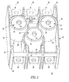
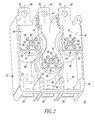
- a three-pole limiter 20 includes a housing 22 (a portion of which, including a cover, is not shown for convenience of illustration in order to show internal structures) having a first surface 24, a second surface 26 opposite and distal from the first surface 24, a plurality of first terminals 28 (e.g., without limitation, load terminals) disposed proximate the first surface 24, a plurality of second terminals 30 (shown in phantom line drawing in Figure 1 ; shown in Figure 2 ) (e.g., without limitation, line terminals), and a plurality of sides 32,34,36,38 disposed between the first and second surfaces 24,26.
- a housing 22 having a first surface 24, a second surface 26 opposite and distal from the first surface 24, a plurality of first terminals 28 (e.g., without limitation, load terminals) disposed proximate the first surface 24, a plurality of second terminals 30 (shown in phantom line drawing in Figure 1 ; shown in Figure 2 ) (e.g., without limitation
- Each of the second terminals 30 includes a conductor 40 ( Figure 2 ) disposed proximate the second surface 26.
- Three current limiters 42,44,46 are housed by the housing 22 and include (as shown with current limiter 42) a first end 48 disposed proximate the first surface 24 and being electrically connected to a corresponding one of the first terminals 28, a second end 50 disposed proximate the second surface 26 and being electrically connected to the conductor 40 ( Figure 2 ) of a corresponding one of the second terminals 30, and an elongated body 52 disposed between the first and second current limiter ends 48,50.
- the individual current limiters 42,44,46 are positioned "on-end" (i.e., the central axis of the current limiter is disposed at about 90 degrees (about normal) with respect to the generally longitudinal axis of the line and load terminals 28,30) on the first terminals 28 in the three-pole current limiter housing 22.
- This enables the three-pole limiter housing 22 to be relatively shorter in length than if the three current limiters 42,44,46 were positioned on their sides (not shown).
- a non-limiting example of the current limiters 42,44,46 is a model NB Tri-Pac Limiter 800NBP20 marketed by Eaton Electrical, Inc. of Beaver, Pennsylvania.
- the first current limiter 42 is proximate the first and second sides 32,34
- the second current limiter 44 is proximate the second and third sides 34,36
- the third current limiter 46 is proximate the fourth side 38.
- the elongated generally cylindrical bodies 52 of the current limiters 42,44,46 are disposed in a V-shaped configuration (as best shown in Figure 2 ) within the housing 22.
- the individual current limiters 42,44,46 preferably each include a plunger 54 disposed from the second end 50 thereof.
- the plungers 54 of the first and second current limiters 42,44 define a straight or substantially straight line 56, and the plunger 54 of the third current limiter 46 is offset from the straight or substantially straight line 56.
- the plungers 54 extend away from the current limiter bodies 52 and away from the ends 48,50 in order to indicate to the user what specific pole(s) is(are) open circuit(s) as resulting from short circuit condition(s).
- each of the conductors 40 of the second terminals 30 is electrically connected to the second end 50 of the corresponding current limiter 42,44,46 with four screws 58.
- a hole 60 in the conductor 40 of each second terminal 30 permits that terminal to clear the plunger 54 when it extends outwardly from the current limiters 42,44,46, as will be discussed.
- Each first terminal 28 is similarly electrically connected to the first end 48 of the corresponding current limiter 42,44,46.
- screws 62 go through the bottom (with respect to Figures 1 , 2 and 5 ) of the current limiter housing 22 (or the housing 78 of Figure 5 ), go through the corresponding first terminal 28 and are threaded into openings 64 ( Figure 5 ) in the first end 48 of the corresponding current limiter 42,44,46.
- each of the first terminals 28 has a first generally longitudinal axis 66
- the conductor 40 of each of the second terminals 30 has a second generally longitudinal axis 68
- the plunger 54 of each of the current limiters 42,44,46 has a third longitudinal axis 70, which is normal to the first and second generally longitudinal axes 66,68.
- Figure 3 shows another three-pole current limiter 72 in which three indicators 74 are in a normal position (e.g., flush or somewhat recessed with respect to the cover 76 of the housing 78).
- the three-pole current limiter 72 may be substantially the same as the three-pole current limiter 20 of Figures 1 and 2 , except for the presence and the positions of the three indicators 74 as held by the housing 78, as will be explained.
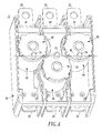
- the cover 76 ( Figure 3 ) of the three-pole current limiter 72 is removed to show the three indicators 74 and the corresponding current limiters 42,44,46, which current limiters are held by the housing 78 in a similar manner as they are held by the housing 22 of Figures 1 and 2 .
- the indicators 74 are carried by indicator members 80 (shown in Figures 4-6 ), which rest on the plungers 54 ( Figure 5 ) of the current limiters 42,44,46 of Figure 4 .
- the orientation of two of the indicator members 80 (associated with current limiters 42,44) is rotated by about 180 degrees with respect to the different orientation of the other indicator member 80 (associated with current limiter 46).
- the limiter cover 76 has a surface 82 with three openings 84 disposed along a straight or substantially straight line 86. As was shown in Figure 1 , only the plungers 54 of the current limiters 42,44 define the straight or substantially straight line 56, while the plunger 54 of the other current limiter 46 is offset from the straight or substantially straight line 56.
- the indicator members 80 (shown in phantom line drawing) and the housing 78 are structured to carry two of the indicator members 80 (associated with current limiters 42,44) in an opposite orientation with respect to the orientation of the other indicator member 80 (associated with current limiter 46), in order that the indicator 74 of each of the indicator members 80 is positioned in a straight or substantially straight line 88 ( Figure 4 ) and is disposable through the corresponding one of the openings 84 ( Figure 3 ) of the housing surface 82.
- each of the indicators 74 e.g., without limitation, knobs
- the indicator 74 is disposable through the corresponding one of the openings 84 (only one opening 84 is shown in Figure 5 ) of the housing surface 82.
- the indicator 74 is either flush with or slightly recessed from the surface 82 for the closed circuit condition of the corresponding one of the current limiters 42,44,46.
- Each of the indicator members 80 includes a first end 92, and a second end 94 opposite and distal from the first end 92, with the indicator 74 being disposed from the first end 92.
- the indicator member second end 94 is engaged by the plunger 54 of a corresponding one of the current limiters 42,44,46.
- the indicator spring 90 biases the corresponding indicator member 80 away from the housing surface 82 of the limiter cover 76.
- the plunger 54 of the corresponding one of the current limiters 42,44,46 is disposable through an aperture 96 of the current limiter end 50 in response to an open circuit condition thereof. Extension of the plunger 54 overcomes the force of the corresponding indicator spring 90 and pushes the corresponding one of the indicators 74 through a corresponding one of the openings 84.
- the extended plunger 54 moves the second end 94 and, thus, the first end 92 and the indicator 74 of the corresponding one of the indicator members 80 through the corresponding one of the openings 84 of the housing surface 82.
- the assembly of Figure 5 is mounted into the base 98 and the cover 76 of the housing 78 of Figure 3 .
- the indicator member 80 and the indicator spring 90 are employed for each pole of the three-pole current limiter 72, in order to provide an indication of the conductive state of the individual current limiters 42,44,46.
- the indicator member 80 is held in place by plural grooves 101, 102, 103, 104 in the cover 76 ( Figure 7 ) of the molded housing 78.
- the indicator member 80 is pushed against the current limiter plunger 54 by the indicator spring 90 to prevent a false "fused" indication of the current limiter state.
- the corresponding indicator spring 90 biases the corresponding indicator member 80 away from the cover 76 and against the plunger 54 of the corresponding current limiter 42,44,46 regardless of the open circuit condition or the closed circuit condition thereof.
- the indicator member 80 Upon release of the plunger 54 from the corresponding current limiter 42,44,46, which opens during the interruption of a fault, the indicator member 80 is pushed by the plunger 54, which overcomes the bias spring force, toward the housing cover 76 until a portion of the indicator 74 protrudes through (as shown in phantom line drawing in Figure 5 ) the corresponding opening 84 in the cover 76. This provides a positive "fused" indicator for the corresponding pole.
- the indicator member 80 fits in the cover grooves 101,102,103,104 ( Figure 7 ) in a reversible fashion for the pole of the current limiter 46, in order to enable the three indicators 74 to be shown uniformly in the straight or substantially straight line 86 ( Figure 3 ) at the surface 82 of the housing cover 76. Hence, this compensates for the staggered alignment of the three "on-end" current limiters 42,44,46 within the housing 78 of Figure 4 .
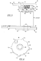
- Figure 6 shows the indicator member 80 of Figures 4 and 5 .
- the indicator 74 shows through (as shown in phantom line drawing in Figure 5 ) the corresponding cover opening 84 to indicate the state of the corresponding current limiter 42,44,46.
- a seat 106 on the first end 92 is provided for the indicator spring 90 ( Figure 5 ).
- the indicator member 80 includes a periphery 107 having six alignment protrusions (e.g., tabs) of various widths 108,110,112,114, which fit into the respective grooves 101,102,103,104 of the housing cover 76 ( Figure 7 ).
- the indicator spring 90 ( Figure 5 ) is disposed between the indicator member 80 and the cover 76 to bias the indicator member 80 to always engage the current limiter plunger 54 regardless of its normal retracted or extended positions.
- each of the alignment protrusions 108,110,112,114 (shown in phantom line drawing) is slidably engaged by a number of the corresponding grooves 101,102,103,104, respectively, of the cover 76.
- the protrusions 108,110,112,114 maintain the first orientation or the different second orientation of the corresponding one of the indicator members 80 when that indicator member is biased away from the cover 76 of the housing 78, and when the indicator 74 of that indicator member is disposed through the corresponding housing opening 84 ( Figure 5 ).
- the grooves 101,102,103,104 advantageously carry two indicator members 80 in the first orientation and the other indicator member 80 in the different second orientation, in order that the indicators 74 are positioned in the straight or substantially straight line 88 ( Figure 4 ) and are disposable through the corresponding housing openings 84.
- Figure 8 shows an electrical switching apparatus 120 including a conventional three-pole circuit interrupter, such as circuit breaker 122, and the three-pole limiter 72 of Figure 3 (for convenience of illustration, only the current limiter 46 is shown). Although not shown, the limiter 20 of Figure 1 interfaces the circuit breaker 122 in the same manner as does the limiter 72.
- a conventional three-pole circuit interrupter such as circuit breaker 122
- the three-pole limiter 72 of Figure 3 for convenience of illustration, only the current limiter 46 is shown.
- the limiter 20 of Figure 1 interfaces the circuit breaker 122 in the same manner as does the limiter 72.
- the circuit breaker 122 includes a housing 124, first terminals (T) 126 (e.g., line) (for convenience of illustration, only one terminal 126 is shown, it being understood that the three-pole circuit breaker 122 has three such terminals), second terminals 128 (e.g., load) (for convenience of illustration, only one terminal 128 is shown, it being understood that the three-pole circuit breaker 122 has three such terminals), three separable contacts 130 (for convenience of illustration, only one pair of separable contacts 130 is shown, it being understood that the three-pole circuit breaker 122 has three such pairs) electrically connected between the corresponding first and second terminals 126,128, and an operating mechanism 132 structured to open and close the separable contacts 130.
- the terminals 30 (e.g., line) of the limiter 72 are electrically connected (by a suitable fastener (not shown)) to the corresponding second terminals 128 of the circuit breaker 122.
Landscapes
- Breakers (AREA)
Applications Claiming Priority (1)
| Application Number | Priority Date | Filing Date | Title |
|---|---|---|---|
| US11/740,522 US7558040B2 (en) | 2007-04-26 | 2007-04-26 | Trip indicator member, and limiter and electrical switching apparatus including a plurality of trip indicator members |
Publications (3)
| Publication Number | Publication Date |
|---|---|
| EP1986212A2 true EP1986212A2 (de) | 2008-10-29 |
| EP1986212A3 EP1986212A3 (de) | 2009-12-09 |
| EP1986212B1 EP1986212B1 (de) | 2011-09-07 |
Family
ID=39683467
Family Applications (1)
| Application Number | Title | Priority Date | Filing Date |
|---|---|---|---|
| EP08007839A Not-in-force EP1986212B1 (de) | 2007-04-26 | 2008-04-23 | Auslöseranzeigeglied und Abgrenzung und elektrische Schaltvorrichtung mit mehreren Auslöseranzeigegliedern |
Country Status (5)
| Country | Link |
|---|---|
| US (1) | US7558040B2 (de) |
| EP (1) | EP1986212B1 (de) |
| CN (1) | CN101295607B (de) |
| AU (1) | AU2008201800B2 (de) |
| CA (1) | CA2629585A1 (de) |
Families Citing this family (3)
| Publication number | Priority date | Publication date | Assignee | Title |
|---|---|---|---|---|
| US8243411B2 (en) * | 2009-12-22 | 2012-08-14 | Schneider Electric USA, Inc. | Electronic miniature circuit breaker with trip indication using the breaker tripping function as the feedback mechanism |
| US8138439B2 (en) | 2010-02-11 | 2012-03-20 | Eaton Corporation | Limiter including a number of gas channels and electrical switching apparatus employing the same |
| US8643501B2 (en) | 2010-06-02 | 2014-02-04 | Eaton Corporation | Metering apparatus |
Citations (29)
| Publication number | Priority date | Publication date | Assignee | Title |
|---|---|---|---|---|
| US2526448A (en) | 1949-08-25 | 1950-10-17 | Mcgraw Electric Co | Arc extinguishing material |
| US3242291A (en) | 1963-01-18 | 1966-03-22 | Westinghouse Electric Corp | Gas-evolving arc-elongating highvoltage fuse |
| US3582586A (en) | 1966-03-21 | 1971-06-01 | Rostone Corp | Arc-interrupting materials and apparatus |
| US3761660A (en) | 1970-07-30 | 1973-09-25 | Rostone Corp | Arc interrupting composition and apparatus |
| US3925745A (en) | 1974-06-27 | 1975-12-09 | Westinghouse Electric Corp | High voltage fuse with localized gas evolving suppressors |
| US4008452A (en) | 1975-08-01 | 1977-02-15 | Westinghouse Electric Corporation | Current limiting fuse device for relatively high current |
| US4035755A (en) | 1975-09-16 | 1977-07-12 | Westinghouse Electric Corporation | Non-venting expulsion fuse |
| US4099153A (en) | 1976-03-08 | 1978-07-04 | Westinghouse Electric Corp. | Gas evolving clamp for current limiting fuse |
| US4166266A (en) | 1978-03-06 | 1979-08-28 | Gould Inc. | Electric fuse having composite support for fusible element |
| US4167723A (en) | 1978-01-09 | 1979-09-11 | Gould Inc. | Electric fuse having gas-evolving material |
| US4179677A (en) | 1978-05-15 | 1979-12-18 | Gould Inc. | Combination of fusible elements for electric fuses |
| US4251699A (en) | 1976-07-26 | 1981-02-17 | S & C Electric Company | Arc extinguishing material comprising dicyandiamide |
| US4307368A (en) | 1980-09-22 | 1981-12-22 | Gould Inc. | Electric fuse having gas evolving means for limiting burnback |
| US4309684A (en) | 1980-09-22 | 1982-01-05 | Gould Inc. | Electric fuse having large cycling ability and gas-evolving means |
| US4319212A (en) | 1981-04-06 | 1982-03-09 | General Electric Company | Fuse supporting means having notches containing a gas evolving material |
| US4339742A (en) | 1981-06-04 | 1982-07-13 | General Electric Company | High voltage fuse having mounted gas evolving members and method of forming such |
| US4340790A (en) | 1976-08-20 | 1982-07-20 | General Electric Company | Electrical switch with melamine loaded thermoplastic ablative material |
| US4444671A (en) | 1976-03-29 | 1984-04-24 | S&C Electric Company | Arc extinguishing material |
| US4520337A (en) | 1984-07-23 | 1985-05-28 | Westinghouse Electric Corp. | Boric acid expulsion fuse |
| US4625195A (en) | 1984-12-03 | 1986-11-25 | Gould Inc. | Electric fuse having positioning means for arc-quenching core |
| US4638283A (en) | 1985-11-19 | 1987-01-20 | General Electric Company | Exothermically assisted electric fuse |
| US4778958A (en) | 1985-04-01 | 1988-10-18 | Doduco Kg. Dr. Eugen Durrwachter | Material for electric contacts having arc-quenching properties |
| US4808963A (en) | 1987-12-24 | 1989-02-28 | Westinghouse Electric Corp. | Replaceable high current draw out fuseholder |
| US4950852A (en) | 1989-04-03 | 1990-08-21 | General Electric Company | Electric circuit breaker arc chute composition |
| US4952900A (en) | 1989-12-04 | 1990-08-28 | Westinghouse Electric Corp. | Controlled seal for an expulsion fuse and method of assembling same |
| US4975551A (en) | 1989-12-22 | 1990-12-04 | S & C Electric Company | Arc-extinguishing composition and articles manufactured therefrom |
| US4995886A (en) | 1989-12-04 | 1991-02-26 | Westinghouse Electric Corp. | Method of assembling a controlled seal for an expulsion fuse |
| US5471185A (en) | 1994-12-06 | 1995-11-28 | Eaton Corporation | Electrical circuit protection devices comprising conductive liquid compositions |
| US20060267720A1 (en) | 2005-05-24 | 2006-11-30 | Eaton Corporation | Electrical switching apparatus and limiter including trip indicator member |
Family Cites Families (12)
| Publication number | Priority date | Publication date | Assignee | Title |
|---|---|---|---|---|
| US2950370A (en) * | 1956-12-10 | 1960-08-23 | Kenneth W Swain | Circuit interrupting building blocks |
| AT264649B (de) * | 1965-03-23 | 1968-09-10 | Krone Kg | Dreipoliger Hochspannungsschalter in gekapselter Bauweise |
| US3593251A (en) * | 1968-08-15 | 1971-07-13 | Westinghouse Electric Corp | Fuse device |
| US3718406A (en) * | 1971-03-22 | 1973-02-27 | Borg Warner | Centrifugal pump with integral seal pressure balance |
| FR2244253A2 (en) * | 1973-09-13 | 1975-04-11 | Unelec | Fused switch or contact breaker - provides button indication of switch status in integral switch and fuse box |
| US4599671A (en) | 1984-07-20 | 1986-07-08 | Westinghouse Electric Corp. | Current limiting devices utilizing resistive parallel rails |
| US4598332A (en) | 1984-07-20 | 1986-07-01 | Westinghouse Electric Corp. | Current limiting apparatus utilizing multiple resistive parallel rails |
| US5269706A (en) * | 1992-06-25 | 1993-12-14 | Bremas S.P.A. | Modular fuse-holder device for connection to a switch or the like |
| DE4330607A1 (de) | 1993-09-09 | 1995-03-16 | Siemens Ag | Limiter zur Strombegrenzung |
| US5587570A (en) * | 1994-07-11 | 1996-12-24 | General Electric Company | Circuit breaker interlock unit to prevent single phasing |
| US6771477B2 (en) * | 2000-11-29 | 2004-08-03 | Canadian Shunt Industries Ltd. | Fused electrical disconnect device |
| FR2829872B1 (fr) * | 2001-09-19 | 2004-01-30 | Ferraz Shawmut | Dispositif pour equiper plusieurs lignes electriques chacune avec un fusible de securite |
-
2007
- 2007-04-26 US US11/740,522 patent/US7558040B2/en not_active Expired - Fee Related
-
2008
- 2008-04-23 EP EP08007839A patent/EP1986212B1/de not_active Not-in-force
- 2008-04-23 CA CA002629585A patent/CA2629585A1/en not_active Abandoned
- 2008-04-24 AU AU2008201800A patent/AU2008201800B2/en not_active Ceased
- 2008-04-28 CN CN2008100912736A patent/CN101295607B/zh not_active Expired - Fee Related
Patent Citations (29)
| Publication number | Priority date | Publication date | Assignee | Title |
|---|---|---|---|---|
| US2526448A (en) | 1949-08-25 | 1950-10-17 | Mcgraw Electric Co | Arc extinguishing material |
| US3242291A (en) | 1963-01-18 | 1966-03-22 | Westinghouse Electric Corp | Gas-evolving arc-elongating highvoltage fuse |
| US3582586A (en) | 1966-03-21 | 1971-06-01 | Rostone Corp | Arc-interrupting materials and apparatus |
| US3761660A (en) | 1970-07-30 | 1973-09-25 | Rostone Corp | Arc interrupting composition and apparatus |
| US3925745A (en) | 1974-06-27 | 1975-12-09 | Westinghouse Electric Corp | High voltage fuse with localized gas evolving suppressors |
| US4008452A (en) | 1975-08-01 | 1977-02-15 | Westinghouse Electric Corporation | Current limiting fuse device for relatively high current |
| US4035755A (en) | 1975-09-16 | 1977-07-12 | Westinghouse Electric Corporation | Non-venting expulsion fuse |
| US4099153A (en) | 1976-03-08 | 1978-07-04 | Westinghouse Electric Corp. | Gas evolving clamp for current limiting fuse |
| US4444671A (en) | 1976-03-29 | 1984-04-24 | S&C Electric Company | Arc extinguishing material |
| US4251699A (en) | 1976-07-26 | 1981-02-17 | S & C Electric Company | Arc extinguishing material comprising dicyandiamide |
| US4340790A (en) | 1976-08-20 | 1982-07-20 | General Electric Company | Electrical switch with melamine loaded thermoplastic ablative material |
| US4167723A (en) | 1978-01-09 | 1979-09-11 | Gould Inc. | Electric fuse having gas-evolving material |
| US4166266A (en) | 1978-03-06 | 1979-08-28 | Gould Inc. | Electric fuse having composite support for fusible element |
| US4179677A (en) | 1978-05-15 | 1979-12-18 | Gould Inc. | Combination of fusible elements for electric fuses |
| US4309684A (en) | 1980-09-22 | 1982-01-05 | Gould Inc. | Electric fuse having large cycling ability and gas-evolving means |
| US4307368A (en) | 1980-09-22 | 1981-12-22 | Gould Inc. | Electric fuse having gas evolving means for limiting burnback |
| US4319212A (en) | 1981-04-06 | 1982-03-09 | General Electric Company | Fuse supporting means having notches containing a gas evolving material |
| US4339742A (en) | 1981-06-04 | 1982-07-13 | General Electric Company | High voltage fuse having mounted gas evolving members and method of forming such |
| US4520337A (en) | 1984-07-23 | 1985-05-28 | Westinghouse Electric Corp. | Boric acid expulsion fuse |
| US4625195A (en) | 1984-12-03 | 1986-11-25 | Gould Inc. | Electric fuse having positioning means for arc-quenching core |
| US4778958A (en) | 1985-04-01 | 1988-10-18 | Doduco Kg. Dr. Eugen Durrwachter | Material for electric contacts having arc-quenching properties |
| US4638283A (en) | 1985-11-19 | 1987-01-20 | General Electric Company | Exothermically assisted electric fuse |
| US4808963A (en) | 1987-12-24 | 1989-02-28 | Westinghouse Electric Corp. | Replaceable high current draw out fuseholder |
| US4950852A (en) | 1989-04-03 | 1990-08-21 | General Electric Company | Electric circuit breaker arc chute composition |
| US4952900A (en) | 1989-12-04 | 1990-08-28 | Westinghouse Electric Corp. | Controlled seal for an expulsion fuse and method of assembling same |
| US4995886A (en) | 1989-12-04 | 1991-02-26 | Westinghouse Electric Corp. | Method of assembling a controlled seal for an expulsion fuse |
| US4975551A (en) | 1989-12-22 | 1990-12-04 | S & C Electric Company | Arc-extinguishing composition and articles manufactured therefrom |
| US5471185A (en) | 1994-12-06 | 1995-11-28 | Eaton Corporation | Electrical circuit protection devices comprising conductive liquid compositions |
| US20060267720A1 (en) | 2005-05-24 | 2006-11-30 | Eaton Corporation | Electrical switching apparatus and limiter including trip indicator member |
Also Published As
| Publication number | Publication date |
|---|---|
| CN101295607B (zh) | 2013-07-17 |
| AU2008201800B2 (en) | 2011-09-29 |
| US7558040B2 (en) | 2009-07-07 |
| AU2008201800A1 (en) | 2008-11-13 |
| CA2629585A1 (en) | 2008-10-26 |
| US20080266732A1 (en) | 2008-10-30 |
| EP1986212A3 (de) | 2009-12-09 |
| EP1986212B1 (de) | 2011-09-07 |
| CN101295607A (zh) | 2008-10-29 |
Similar Documents
| Publication | Publication Date | Title |
|---|---|---|
| CA2629583A1 (en) | Pocket with secure dividers | |
| EP0514454B1 (de) | Vorrichtung zum motor- und kurzschlussschutz | |
| US6342994B1 (en) | Protective device against excessive currents, in particular for resettable protection of a controlled switch | |
| US7656640B2 (en) | Voltage surge protection device | |
| US10014098B2 (en) | Surge protection device, comprising at least one surge arrester and one short-circuit switching device which is connected in parallel with the surge arrester, can be thermally tripped and is spring-pretensioned | |
| US4617544A (en) | High voltage, high rupture capacity fuse | |
| US6256183B1 (en) | Time delay fuse with mechanical overload device and indicator actuator | |
| CN101964519A (zh) | 用于保护电气设施免受瞬态电压浪涌的设备 | |
| JP5890030B2 (ja) | 回路保護デバイス | |
| CA2789187C (en) | Limiter including a number of gas channels and electrical switching apparatus employing the same | |
| US7362207B2 (en) | Electrical switching apparatus and limiter including trip indicator member | |
| US20240194433A1 (en) | Surge protective device including bimetallic fuse element | |
| US20160042903A1 (en) | Automotive circuit breaker including circuit breaker with integrated secondary current protection | |
| EP1986212B1 (de) | Auslöseranzeigeglied und Abgrenzung und elektrische Schaltvorrichtung mit mehreren Auslöseranzeigegliedern | |
| JP5847236B2 (ja) | 回路保護デバイス | |
| US5933311A (en) | Circuit breaker including positive temperature coefficient resistivity elements having a reduced tolerance | |
| US20100276395A1 (en) | 35kV Rubber Molded Fused Vacuum Interrupter | |
| US9911567B2 (en) | Disconnect switch with integrated thermal breaker | |
| US6020802A (en) | Circuit breaker including two magnetic coils and a positive temperature coefficient resistivity element | |
| US20190066954A1 (en) | Fuse and trip mechanism therefor | |
| US6144540A (en) | Current suppressing circuit breaker unit for inductive motor protection | |
| CA1181788A (en) | Low current clearing back-up fuse | |
| HK1180451A1 (zh) | 具有用於提高运行可靠性的旋转盘以及电子组装的过压断路器 |
Legal Events
| Date | Code | Title | Description |
|---|---|---|---|
| PUAI | Public reference made under article 153(3) epc to a published international application that has entered the european phase |
Free format text: ORIGINAL CODE: 0009012 |
|
| AK | Designated contracting states |
Kind code of ref document: A2 Designated state(s): AT BE BG CH CY CZ DE DK EE ES FI FR GB GR HR HU IE IS IT LI LT LU LV MC MT NL NO PL PT RO SE SI SK TR |
|
| AX | Request for extension of the european patent |
Extension state: AL BA MK RS |
|
| PUAL | Search report despatched |
Free format text: ORIGINAL CODE: 0009013 |
|
| AK | Designated contracting states |
Kind code of ref document: A3 Designated state(s): AT BE BG CH CY CZ DE DK EE ES FI FR GB GR HR HU IE IS IT LI LT LU LV MC MT NL NO PL PT RO SE SI SK TR |
|
| AX | Request for extension of the european patent |
Extension state: AL BA MK RS |
|
| RIC1 | Information provided on ipc code assigned before grant |
Ipc: H01H 85/30 20060101ALI20091102BHEP Ipc: H01H 85/20 20060101AFI20080819BHEP Ipc: H01H 9/10 20060101ALI20091102BHEP |
|
| 17P | Request for examination filed |
Effective date: 20100609 |
|
| AKX | Designation fees paid |
Designated state(s): DE FR GB IT |
|
| GRAP | Despatch of communication of intention to grant a patent |
Free format text: ORIGINAL CODE: EPIDOSNIGR1 |
|
| GRAS | Grant fee paid |
Free format text: ORIGINAL CODE: EPIDOSNIGR3 |
|
| GRAA | (expected) grant |
Free format text: ORIGINAL CODE: 0009210 |
|
| REG | Reference to a national code |
Ref country code: GB Ref legal event code: FG4D |
|
| REG | Reference to a national code |
Ref country code: DE Ref legal event code: R096 Ref document number: 602008009446 Country of ref document: DE Effective date: 20111201 |
|
| PLBE | No opposition filed within time limit |
Free format text: ORIGINAL CODE: 0009261 |
|
| STAA | Information on the status of an ep patent application or granted ep patent |
Free format text: STATUS: NO OPPOSITION FILED WITHIN TIME LIMIT |
|
| 26N | No opposition filed |
Effective date: 20120611 |
|
| REG | Reference to a national code |
Ref country code: DE Ref legal event code: R097 Ref document number: 602008009446 Country of ref document: DE Effective date: 20120611 |
|
| PGFP | Annual fee paid to national office [announced via postgrant information from national office to epo] |
Ref country code: GB Payment date: 20130326 Year of fee payment: 6 |
|
| PGFP | Annual fee paid to national office [announced via postgrant information from national office to epo] |
Ref country code: DE Payment date: 20130430 Year of fee payment: 6 |
|
| PGFP | Annual fee paid to national office [announced via postgrant information from national office to epo] |
Ref country code: IT Payment date: 20130416 Year of fee payment: 6 Ref country code: FR Payment date: 20130417 Year of fee payment: 6 |
|
| REG | Reference to a national code |
Ref country code: DE Ref legal event code: R119 Ref document number: 602008009446 Country of ref document: DE |
|
| GBPC | Gb: european patent ceased through non-payment of renewal fee |
Effective date: 20140423 |
|
| REG | Reference to a national code |
Ref country code: FR Ref legal event code: ST Effective date: 20141231 |
|
| PG25 | Lapsed in a contracting state [announced via postgrant information from national office to epo] |
Ref country code: GB Free format text: LAPSE BECAUSE OF NON-PAYMENT OF DUE FEES Effective date: 20140423 Ref country code: DE Free format text: LAPSE BECAUSE OF NON-PAYMENT OF DUE FEES Effective date: 20141101 |
|
| REG | Reference to a national code |
Ref country code: DE Ref legal event code: R119 Ref document number: 602008009446 Country of ref document: DE Effective date: 20141101 |
|
| PG25 | Lapsed in a contracting state [announced via postgrant information from national office to epo] |
Ref country code: FR Free format text: LAPSE BECAUSE OF NON-PAYMENT OF DUE FEES Effective date: 20140430 |
|
| PG25 | Lapsed in a contracting state [announced via postgrant information from national office to epo] |
Ref country code: IT Free format text: LAPSE BECAUSE OF NON-PAYMENT OF DUE FEES Effective date: 20140423 |