EP1985812A1 - V-type engine - Google Patents
V-type engine Download PDFInfo
- Publication number
- EP1985812A1 EP1985812A1 EP08251514A EP08251514A EP1985812A1 EP 1985812 A1 EP1985812 A1 EP 1985812A1 EP 08251514 A EP08251514 A EP 08251514A EP 08251514 A EP08251514 A EP 08251514A EP 1985812 A1 EP1985812 A1 EP 1985812A1
- Authority
- EP
- European Patent Office
- Prior art keywords
- intake
- exhaust
- cam followers
- banks
- camshaft
- Prior art date
- Legal status (The legal status is an assumption and is not a legal conclusion. Google has not performed a legal analysis and makes no representation as to the accuracy of the status listed.)
- Granted
Links
- 238000001816 cooling Methods 0.000 claims description 9
- 230000006835 compression Effects 0.000 claims description 5
- 238000007906 compression Methods 0.000 claims description 5
- 238000009751 slip forming Methods 0.000 claims description 3
- 230000002093 peripheral effect Effects 0.000 claims description 2
- 238000009413 insulation Methods 0.000 description 8
- 238000002485 combustion reaction Methods 0.000 description 6
- 230000000694 effects Effects 0.000 description 6
- 238000005520 cutting process Methods 0.000 description 4
- 230000009467 reduction Effects 0.000 description 4
- 238000011144 upstream manufacturing Methods 0.000 description 4
- 230000005540 biological transmission Effects 0.000 description 3
- 230000015572 biosynthetic process Effects 0.000 description 3
- 238000000034 method Methods 0.000 description 3
- 239000010687 lubricating oil Substances 0.000 description 2
- 229910000831 Steel Inorganic materials 0.000 description 1
- 230000006837 decompression Effects 0.000 description 1
- 230000002349 favourable effect Effects 0.000 description 1
- 230000006872 improvement Effects 0.000 description 1
- 238000009434 installation Methods 0.000 description 1
- 230000002452 interceptive effect Effects 0.000 description 1
- 239000000463 material Substances 0.000 description 1
- 230000007246 mechanism Effects 0.000 description 1
- 238000012986 modification Methods 0.000 description 1
- 230000004048 modification Effects 0.000 description 1
- 239000007858 starting material Substances 0.000 description 1
- 239000010959 steel Substances 0.000 description 1
- 239000013585 weight reducing agent Substances 0.000 description 1
Images







Classifications
-
- F—MECHANICAL ENGINEERING; LIGHTING; HEATING; WEAPONS; BLASTING
- F01—MACHINES OR ENGINES IN GENERAL; ENGINE PLANTS IN GENERAL; STEAM ENGINES
- F01L—CYCLICALLY OPERATING VALVES FOR MACHINES OR ENGINES
- F01L1/00—Valve-gear or valve arrangements, e.g. lift-valve gear
- F01L1/12—Transmitting gear between valve drive and valve
- F01L1/14—Tappets; Push rods
- F01L1/146—Push-rods
-
- F—MECHANICAL ENGINEERING; LIGHTING; HEATING; WEAPONS; BLASTING
- F01—MACHINES OR ENGINES IN GENERAL; ENGINE PLANTS IN GENERAL; STEAM ENGINES
- F01L—CYCLICALLY OPERATING VALVES FOR MACHINES OR ENGINES
- F01L13/00—Modifications of valve-gear to facilitate reversing, braking, starting, changing compression ratio, or other specific operations
- F01L13/08—Modifications of valve-gear to facilitate reversing, braking, starting, changing compression ratio, or other specific operations for decompression, e.g. during starting; for changing compression ratio
- F01L13/085—Modifications of valve-gear to facilitate reversing, braking, starting, changing compression ratio, or other specific operations for decompression, e.g. during starting; for changing compression ratio the valve-gear having an auxiliary cam protruding from the main cam profile
-
- F—MECHANICAL ENGINEERING; LIGHTING; HEATING; WEAPONS; BLASTING
- F01—MACHINES OR ENGINES IN GENERAL; ENGINE PLANTS IN GENERAL; STEAM ENGINES
- F01L—CYCLICALLY OPERATING VALVES FOR MACHINES OR ENGINES
- F01L3/00—Lift-valve, i.e. cut-off apparatus with closure members having at least a component of their opening and closing motion perpendicular to the closing faces; Parts or accessories thereof
-
- F—MECHANICAL ENGINEERING; LIGHTING; HEATING; WEAPONS; BLASTING
- F02—COMBUSTION ENGINES; HOT-GAS OR COMBUSTION-PRODUCT ENGINE PLANTS
- F02F—CYLINDERS, PISTONS OR CASINGS, FOR COMBUSTION ENGINES; ARRANGEMENTS OF SEALINGS IN COMBUSTION ENGINES
- F02F1/00—Cylinders; Cylinder heads
- F02F1/002—Integrally formed cylinders and cylinder heads
-
- F—MECHANICAL ENGINEERING; LIGHTING; HEATING; WEAPONS; BLASTING
- F02—COMBUSTION ENGINES; HOT-GAS OR COMBUSTION-PRODUCT ENGINE PLANTS
- F02F—CYLINDERS, PISTONS OR CASINGS, FOR COMBUSTION ENGINES; ARRANGEMENTS OF SEALINGS IN COMBUSTION ENGINES
- F02F7/00—Casings, e.g. crankcases
- F02F7/0002—Cylinder arrangements
- F02F7/0012—Crankcases of V-engines
-
- F—MECHANICAL ENGINEERING; LIGHTING; HEATING; WEAPONS; BLASTING
- F01—MACHINES OR ENGINES IN GENERAL; ENGINE PLANTS IN GENERAL; STEAM ENGINES
- F01L—CYCLICALLY OPERATING VALVES FOR MACHINES OR ENGINES
- F01L1/00—Valve-gear or valve arrangements, e.g. lift-valve gear
- F01L1/12—Transmitting gear between valve drive and valve
- F01L1/18—Rocking arms or levers
- F01L1/181—Centre pivot rocking arms
- F01L1/182—Centre pivot rocking arms the rocking arm being pivoted about an individual fulcrum, i.e. not about a common shaft
-
- F—MECHANICAL ENGINEERING; LIGHTING; HEATING; WEAPONS; BLASTING
- F01—MACHINES OR ENGINES IN GENERAL; ENGINE PLANTS IN GENERAL; STEAM ENGINES
- F01L—CYCLICALLY OPERATING VALVES FOR MACHINES OR ENGINES
- F01L1/00—Valve-gear or valve arrangements, e.g. lift-valve gear
- F01L1/02—Valve drive
- F01L1/04—Valve drive by means of cams, camshafts, cam discs, eccentrics or the like
- F01L1/047—Camshafts
- F01L2001/054—Camshafts in cylinder block
-
- F—MECHANICAL ENGINEERING; LIGHTING; HEATING; WEAPONS; BLASTING
- F01—MACHINES OR ENGINES IN GENERAL; ENGINE PLANTS IN GENERAL; STEAM ENGINES
- F01L—CYCLICALLY OPERATING VALVES FOR MACHINES OR ENGINES
- F01L2303/00—Manufacturing of components used in valve arrangements
-
- F—MECHANICAL ENGINEERING; LIGHTING; HEATING; WEAPONS; BLASTING
- F01—MACHINES OR ENGINES IN GENERAL; ENGINE PLANTS IN GENERAL; STEAM ENGINES
- F01L—CYCLICALLY OPERATING VALVES FOR MACHINES OR ENGINES
- F01L2800/00—Methods of operation using a variable valve timing mechanism
- F01L2800/03—Stopping; Stalling
-
- F—MECHANICAL ENGINEERING; LIGHTING; HEATING; WEAPONS; BLASTING
- F02—COMBUSTION ENGINES; HOT-GAS OR COMBUSTION-PRODUCT ENGINE PLANTS
- F02F—CYLINDERS, PISTONS OR CASINGS, FOR COMBUSTION ENGINES; ARRANGEMENTS OF SEALINGS IN COMBUSTION ENGINES
- F02F1/00—Cylinders; Cylinder heads
- F02F1/02—Cylinders; Cylinder heads having cooling means
- F02F1/04—Cylinders; Cylinder heads having cooling means for air cooling
- F02F1/06—Shape or arrangement of cooling fins; Finned cylinders
Definitions
- the present invention relates to a V-type engine comprising: first and second banks each of which includes a cylinder bore therein, and which are arranged in a V-shape so as to define a valley portion therebetween; a crankcase with which the first and second banks are continuously formed; a crankshaft supported by the crankcase; a cooling fin which protrudes on an outer wall of each of the banks; intake and exhaust valves which are arranged in a V-shape in a head portion of each of the banks; and a valve-operating device which drives the intake and exhaust valves to be opened and closed, the valve-operating device including: a camshaft being disposed above the crankshaft and driven by the crankshaft, first intake and exhaust cam followers and second intake and exhaust cam followers being moved up and down by intake and exhaust cams of the camshaft, respectively, first intake and exhaust push rods and second intake and exhaust push rods, the first intake and exhaust push rods having lower ends which are operatively connected respectively to the first intake and exhaust cam followers, and
- V-type engine is already known as disclosed in, for example, Japanese Patent Application Laid-open No. 3-107515 .
- a V-type engine comprising: first and second banks each of which includes a cylinder bore therein, and which are arranged in a V-shape so as to define a valley portion therebetween; a crankcase with which the first and second banks are continuously formed; a crankshaft supported by the crankcase; a cooling fin which protrudes on an outer wall of each of the banks; intake and exhaust valves which are arranged in a V-shape in a head portion of each of the banks; and a valve-operating device which drives the intake and exhaust valves to be opened and closed, the valve-operating device including: a camshaft being disposed above the crankshaft and driven by the crankshaft, first intake and exhaust cam followers and second intake and exhaust cam followers being moved up and down by intake and exhaust cams of the camshaft, respectively, first intake and exhaust push rods and second intake and exhaust push rods, the first intake and exhaust push rods having lower ends which are operatively connected respectively to the first
- the intake and exhaust rocker arms in each bank are arranged in a substantially inverted-V-shape in the plan view, so that the side end portions of the intake and exhaust rocker arms on the side of the corresponding intake and exhaust push rods are positioned adjacent to each other. Since the intake and exhaust push rods are positioned adjacent to each other, the first and second intake cam followers and the first and second exhaust cam followers can be arranged adjacent to one another on the intermediate portion of a single cam follower shaft. Further, in conjunction with the arrangement of the cam followers, the intake and exhaust cams can be arranged adjacent to each other. As a result, it is possible to achieve a compact valve-operating device, and eventually a compact V-type engine.
- first and second intake cam followers their boss portions abut against each other side by side on the cam follower shaft, while their slipper portions have end portions at one end along the axial direction of the camshaft, which end portions protrude respectively in the opposite directions to each other in such a manner that the slipper portions face each other across the intake cam located therein between.
- first and second exhaust cam followers their boss portions abut against each other side by side on the cam follower shaft, while their slipper portions have end portions at one end along the axial direction of the camshaft, which end portions protrude respectively in the opposite directions to each other in such a manner that the slipper portions face each other across the exhaust cam located in therebetween.
- the intake and exhaust cam, and the first intake and exhaust cam followers as well as the second intake and exhaust cam followers can be concentratedly arranged on the single camshaft and the single cam follower shaft.
- This concentrated arrangement makes it possible to achieve the compact valve- operating device, and in particular, to shorten the camshaft.
- the slipper portions which are positioned respectively on the opposite sides of the corresponding cam, have the end portions at one end along the axial direction of the camshaft, which end portions protrude respectively in the opposite directions to each other in such a manner that the slipper portions face each other across.
- the second feature of the present invention it is possible to achieve a further compact valve-operating device, and also to effectively lubricate the periphery of the intake and exhaust cams with lubricating oil dispersed from around the crankpin while during the crankshaft is rotationed.
- a third feature of the present invention in addition to any one of the first or second feature, further comprising: a flat portion formed in the camshaft so as to extend from an outer peripheral face of the camshaft to a base surface of the exhaust cam; a decompressing member being swingably axis-supported on the flat portion, and including a decompressing arm which is located, over a period between instants when the V-type engine stops and starts, to its operating position on the base surface side of the exhaust cam and protrudes its tip end from the base surface so as to lift the first and second exhaust cam followers in the compression stroke of the V-type engine; and a centrifugal weight which generates a centrifugal force for retreating the decompressing arm from the base surface when the V-type engine is operated at a rotational speed higher than that during the idling of the V-type engine; and a return spring for urging the decompressing arm toward the operating position, the return spring being connected to the decompressing member.
- the third feature of the present invention it is possible to provide the following effect in association with the structure of the first and second exhaust cam followers in which their boss portions abut against each other side by side on the cam follower shaft, and in which their slipper portions have end portions at one end along the axial direction of the camshaft, which end portions protrude respectively in the opposite directions to each other in such a manner that the slipper portions face each other across the exhaust cam located in therebetween.
- the decompressing member 66 only slight protrusion of a tip end portion of the decompressing arm 66a toward the exhaust cam makes it possible to provide very slightly lift to the first and second exhaust cam followers by bringing the tip end portion substantially evenly into sliding contact with the first and second exhaust cam followers.
- the tip end portion of the decompressing arm protrudes by only a small length toward the exhaust cam, it is possible to achieve a compact single decompressing device shared by both the banks, and also to improve the durability of the exhaust cam and the exhaust cam followers while minimizing a reduction in the effective area of the base surface of the exhaust cam due to the formation of the flat portion.
- the flat portion is formed on the camshaft so as to extend from the general surface of the camshaft to the base surface of the exhaust cam, while the decompressing arm of the decompressing member, which is pivotally supported around an axis on the flat portion, is caused to protrude toward the base surface of the exhaust cam when the V-type engine is stopped or started.
- This structure eliminates the need to cause the slipper portions of the exhaust cam followers to protrude outward of the exhaust cam. As a result, it is possible to achieve the decompressing operation performed at the time of start of the V-type engine while maintaining the compactness of the valve-operating device.
- the air-cooled general-purpose V-type engine includes: a crankcase 1; a first bank B1 and a second bank B2 which are arranged respectively on the left and right sides in a V-shape, and which are connected to an upper portion of the crankcase 1; an installation flange 2 formed in a bottom portion of the crankcase 1; and a starter device St provided in one side portion of the crankcase so as to be housed in a space below the first bank B1.
- Each of the first and second banks B1 and B2 includes: a cylinder block 3 which has a cylinder bore 3a, and which is bolt-coupled to the crankcase 1; a cylinder head 4 which has a combustion chamber 4a leading to the cylinder bore 3a, and which is integrally connected to the cylinder block 3; and a head cover 5 bolt-coupled to an end surface of the cylinder head 4.
- Each of the first and second banks B1 and B2 is integrally molded, and has a large number of air-cooling fins 6, 6,... integrally formed to protrude from an outer surface of the bank.
- the first and second banks B1 and B2 are arranged in such a manner that the opening angle ⁇ between the banks B1 and B2, that is, the angle ⁇ formed by a cylinder center line A1 of the first bank B1 and a cylinder center line A2 of the second bank B2 becomes 90°.
- counterweights 7w are attached to the crankshaft 7 on a side opposite to the crankpin 7p. The counterweights 7w balance the inertia forces of the pistons 8 of the respective banks B1 and B2.
- first and second banks B1 and B2 are arranged in such a manner that each of the cylinder center line A1 of the first bank B1 and the cylinder center line A2 of the second bank B2 passes a point P eccentric with respect to a rotational center A3 of the crankshaft 7 to the side opposite to both of the banks B1 and B2.
- This arrangement makes it possible to widen a valley portion 11 defined between the first and second banks B1 and B2 while maintaining the opening angle ⁇ between the banks B1 and B2 at 90°.
- This valley portion 11 houses the entirety of a carburetor C, which is one auxiliary machine of the V-type engine E, and part of an air cleaner Ac having a cleaner element 10 installed therein.
- the carburetor C is a twin carburetor including: a carburetor main body 12; and first and second intake paths 131, 132 extending in a horizontal direction (a direction orthogonal to the crankshaft 7), and being arranged adjacent to each other in the carburetor main body 12 along with the arrangement direction of the first and second banks B1 and B2.
- a float chamber 12a and a fuel-cutting electromagnetic valve 12b are attached to a lower portion of the carburetor main body 12.
- each of the cylinder heads 4, 4 of the first and second banks B1 and B2 includes, in addition to the combustion chamber 4a, an intake port 14 and an exhaust port 15 each opened to the combustion chamber 4a. Opening end portions of the intake and exhaust ports 14, 15 to the combustion chamber 4a are formed respectively in an intake valve seat 80 and an exhaust valve seat 81, in each cylinder head 4.
- the intake valve seat 80 is formed to have a larger diameter than that of the exhaust valve seat 81.
- these intake and exhaust valve seats 80, 81 as well as a plug mounting hole 87, into which an ignition plug 23 is screwed, are arranged adjacent to one another so as to surround the center of the combustion chamber 4a.
- an intake valve 35a, 35b, and an exhaust valve 36a, 36b are attached to the cylinder head 4 of each of the banks B1 and B2.
- the intake valve 35a, 35b opens and closes the corresponding intake port 14 in association with the corresponding intake valve seat 80.
- the exhaust valve 36a, 36b opens and closes the corresponding exhaust port 15 in association with the corresponding exhaust valve seat 81.
- the ignition plug 23 with an electrode facing to the combustion chamber 4a is screwed into the cylinder head 4.
- each intake valve 35a, 35b and the corresponding exhaust valve 36a, 36b are arranged in a V-shape.
- Valve springs 61, 62 are attached respectively to each intake valve 35 and each exhaust valve 36 so as to urge the valves in the valve closing direction.
- Each intake valve 35a, 35b and the corresponding exhaust valve 36a, 36b are arranged in a V-shape.
- the inclination angles ⁇ 1, ⁇ 2 of the axial lines respectively of the intake valve 35a, 35b and the exhaust valve 36a, 36b with respect to the center line of the corresponding cylinder bore 3a are set, as shown in Fig. 10 , in the following manner. Specifically, these inclination angles ⁇ 1 and ⁇ 2 are set as large as possible within a range allowing cutting process performed on the intake and exhaust valve seats 80, 81 with rotary cutting tools 82, 83 inserted into the cylinder bores 3a.
- the first and second intake paths 131, 132 are connected respectively to the intake ports 14, 14 of the first and second banks B1 and B2 with an intake manifold 16 interposed in between.
- the decompressing arm 66a occupies a position at which its tip end protrudes from the base surface of the exhaust cam 38e (see the chain line in FIG. 15 ). Accordingly, even in the compression stroke, the first and second exhaust cam followers 43a, 43b are very slightly lifted by the decompression arm 66a so as to slightly open the exhaust valves 36a, 36b of the first and second banks B1 and B2. The compression pressure in the cylinder bores 3a, 3a is thereby lowered, so that the starting load is alleviated.
- the first bolt holes 31, 31 of the mounting flange 30 of the air cleaner Ac are fitted respectively onto the stud bolts 25, 25.
- the tap bolts 26, 26 are inserted into all the second bolt holes 32, 32, and are thus screwed and fastened into the screw holes 27, 27 of the common flange 20.
- the tap bolts 26, 26 needs to be moved by a distance larger than the total length of the carburetor C.
- each tap bolt 26 is thin, the space for moving the tap bolt 26 can be easily secured in general.
- Each pair of the intake and exhaust push rods 44a, 45a; 44b, 45b, which are disposed outside the banks B1 and B2, are housed in, and protected by, the corresponding rod covers 59, 60, which are supported by the upper-portion and lower-portion support portions 74, 75 protruding toward the valley portion 11 respectively from the upper and lower end portions of the corresponding one of the banks B1 and B2.
- the rod covers 59, 60 are disposed, on the valley portion 11 side, between the first and second banks B1 and B2, the rod covers 59, 60 are protected by the banks B1 and B2 from being brought into contact with foreign objects.
- This structure provides the following effect in association with the aforementioned structure of the first and second exhaust cam followers 43a, 43b in which their boss portions abut against each other side by side on the cam follower shaft, and in which their slipper portions have end portions at one end along the axial direction of the camshaft 38, which end portions protrude respectively in the opposite directions to each other in such a manner that the slipper portions face each other across the exhaust cam located in therebetween.
Landscapes
- Engineering & Computer Science (AREA)
- Mechanical Engineering (AREA)
- General Engineering & Computer Science (AREA)
- Chemical & Material Sciences (AREA)
- Combustion & Propulsion (AREA)
- Valve-Gear Or Valve Arrangements (AREA)
- Cylinder Crankcases Of Internal Combustion Engines (AREA)
Abstract
Description
- The present invention relates to a V-type engine comprising: first and second banks each of which includes a cylinder bore therein, and which are arranged in a V-shape so as to define a valley portion therebetween; a crankcase with which the first and second banks are continuously formed; a crankshaft supported by the crankcase; a cooling fin which protrudes on an outer wall of each of the banks; intake and exhaust valves which are arranged in a V-shape in a head portion of each of the banks; and a valve-operating device which drives the intake and exhaust valves to be opened and closed, the valve-operating device including: a camshaft being disposed above the crankshaft and driven by the crankshaft, first intake and exhaust cam followers and second intake and exhaust cam followers being moved up and down by intake and exhaust cams of the camshaft, respectively, first intake and exhaust push rods and second intake and exhaust push rods, the first intake and exhaust push rods having lower ends which are operatively connected respectively to the first intake and exhaust cam followers, and being disposed on the valley portion side of the first bank, the second intake and exhaust push rods having lower ends which are operatively connected respectively to the second intake and exhaust cam followers, and being disposed on the valley portion side of the second bank, and first intake and exhaust rocker arms and second intake and exhaust rocker arms, the first intake and exhaust rocker arms operatively connecting upper ends of the first intake and exhaust push rods respectively to the intake and exhaust valves of the first bank, the second intake and exhaust rocker arms operatively connecting upper ends of the seconds intake and exhaust push rods respectively to the intake and exhaust valves of the second bank.
- Such a V-type engine is already known as disclosed in, for example, Japanese Patent Application Laid-open No.
3-107515 - In the conventional V-type engine, the distance between intake and exhaust push rods in each bank is increased in association with the V-shape arrangement of intake and exhaust valves in each bank, thus resulting in a difficulty of achieving a more compact valve-operating device.
- The present invention has been made in view of the above-described circumstances. An object of at least the preferred embodiments of the present invention is to provide a V-type engine having the following characteristics. Specifically, the V-type engine has a compact valve-operating device achieved by a sufficiently reduced distance between intake and exhaust push rods in each of banks. In addition, in the V-type engine, sliding contact are as contact portions of intake and exhaust cam followers with corresponding intake and exhaust cams are sufficiently reduced increased, so that the surface pressure of their sliding contact portions is reduced. As a result, the durability of the sliding contact portion areas can be improved.
- According to a first feature of the present invention, there is provided a V-type engine comprising: first and second banks each of which includes a cylinder bore therein, and which are arranged in a V-shape so as to define a valley portion therebetween; a crankcase with which the first and second banks are continuously formed; a crankshaft supported by the crankcase; a cooling fin which protrudes on an outer wall of each of the banks; intake and exhaust valves which are arranged in a V-shape in a head portion of each of the banks; and a valve-operating device which drives the intake and exhaust valves to be opened and closed, the valve-operating device including: a camshaft being disposed above the crankshaft and driven by the crankshaft, first intake and exhaust cam followers and second intake and exhaust cam followers being moved up and down by intake and exhaust cams of the camshaft, respectively, first intake and exhaust push rods and second intake and exhaust push rods, the first intake and exhaust push rods having lower ends which are operatively connected respectively to the first intake and exhaust cam followers, and being disposed on the valley portion side of the first bank, the second intake and exhaust push rods having lower ends which are operatively connected respectively to the second intake and exhaust cam followers, and being disposed on the valley portion side of the second bank, and first intake and exhaust rocker arms and second intake and exhaust rocker arms, the first intake and exhaust rocker arms operatively connecting upper ends of the first intake and exhaust push rods respectively to the intake and exhaust valves of the first bank, the second intake and exhaust rocker arms operatively connecting upper ends of the seconds intake and exhaust push rods respectively to the intake and exhaust valves of the second bank, wherein the intake and exhaust rocker arms in each bank are arranged in a substantially inverted-V-shape in a plan view, so that end portions of the intake and exhaust rocker arms on the side of the corresponding intake and exhaust push rods are positioned adjacent to each other, thereby intake and exhaust push rods are positioned adjacent to each other, each of the cam followers is comprised of a boss portion swingably supported on a single cam follower shaft supported by the crankcase at a position directly above and in parallel with the camshaft, and a slipper portion being in sliding contact with a corresponding one of the intake and exhaust cams, the boss portions of the first and second intake cam followers abut against each other side by side on the cam follower shaft, while their slipper portions have end portions at one end along an axial direction of the camshaft which protrude respectively in opposite directions to each other in such a manner that the slipper portions face each other across the intake cam located therebetween, the boss portions of the first and second exhaust cam followers abut against each other side by side on the cam follower shaft, while their slipper portions have end portions at one end along the axial direction of the camshaft which protrude respectively in opposite directions to each other in such a manner that the slipper portions face each other across the exhaust cam located therebetween, the first and second intake cam followers and the first and second exhaust cam followers are arranged adjacent to one another on an intermediate portion of the cam follower shaft, which is supported, at opposite end portions thereof, by the crankcase, and corresponding to the cam followers, the intake and exhaust cams are arranged adjacent to each other.
- With the first feature of the present invention, the intake and exhaust rocker arms in each bank are arranged in a substantially inverted-V-shape in the plan view, so that the side end portions of the intake and exhaust rocker arms on the side of the corresponding intake and exhaust push rods are positioned adjacent to each other. Since the intake and exhaust push rods are positioned adjacent to each other, the first and second intake cam followers and the first and second exhaust cam followers can be arranged adjacent to one another on the intermediate portion of a single cam follower shaft. Further, in conjunction with the arrangement of the cam followers, the intake and exhaust cams can be arranged adjacent to each other. As a result, it is possible to achieve a compact valve-operating device, and eventually a compact V-type engine.
- Moreover, in the first and second intake cam followers, their boss portions abut against each other side by side on the cam follower shaft, while their slipper portions have end portions at one end along the axial direction of the camshaft, which end portions protrude respectively in the opposite directions to each other in such a manner that the slipper portions face each other across the intake cam located therein between. In addition, in the first and second exhaust cam followers, their boss portions abut against each other side by side on the cam follower shaft, while their slipper portions have end portions at one end along the axial direction of the camshaft, which end portions protrude respectively in the opposite directions to each other in such a manner that the slipper portions face each other across the exhaust cam located in therebetween. Accordingly, the intake and exhaust cam, and the first intake and exhaust cam followers as well as the second intake and exhaust cam followers can be concentratedly arranged on the single camshaft and the single cam follower shaft. This concentrated arrangement makes it possible to achieve the compact valve- operating device, and in particular, to shorten the camshaft. Furthermore, the following effect is provided by the structure in which, in each of the pair of the first and second intake cam followers as well as the pair of the first and second exhaust cam followers, the slipper portions, which are positioned respectively on the opposite sides of the corresponding cam, have the end portions at one end along the axial direction of the camshaft, which end portions protrude respectively in the opposite directions to each other in such a manner that the slipper portions face each other across. Specifically, it is possible to sufficiently secure the sliding contact portions of the pair of the first and second intake cam followers as well as the pair of the first and second exhaust cam followers respectively with the intake and exhaust cams without interfering with the reduction in size of the valve-operating device. As a result, the surface pressure of each of the sliding contact portions of these components is sufficiently reduced, so that the durability of the sliding contact portions can be improved.
- According to a second feature of the present invention, in addition to the first feature, the first and second intake and exhaust cam followers of both of the banks as well as the intake and exhaust cams are mostly placed within a space between planes extended respectively from opposite end surfaces of a crankpin of the crankshaft.
- According to the second feature of the present invention, it is possible to achieve a further compact valve-operating device, and also to effectively lubricate the periphery of the intake and exhaust cams with lubricating oil dispersed from around the crankpin while during the crankshaft is rotationed.
- According to a third feature of the present invention, in addition to any one of the first or second feature, further comprising: a flat portion formed in the camshaft so as to extend from an outer peripheral face of the camshaft to a base surface of the exhaust cam; a decompressing member being swingably axis-supported on the flat portion, and including a decompressing arm which is located, over a period between instants when the V-type engine stops and starts, to its operating position on the base surface side of the exhaust cam and protrudes its tip end from the base surface so as to lift the first and second exhaust cam followers in the compression stroke of the V-type engine; and a centrifugal weight which generates a centrifugal force for retreating the decompressing arm from the base surface when the V-type engine is operated at a rotational speed higher than that during the idling of the V-type engine; and a return spring for urging the decompressing arm toward the operating position, the return spring being connected to the decompressing member.
- According to the third feature of the present invention, it is possible to provide the following effect in association with the structure of the first and second exhaust cam followers in which their boss portions abut against each other side by side on the cam follower shaft, and in which their slipper portions have end portions at one end along the axial direction of the camshaft, which end portions protrude respectively in the opposite directions to each other in such a manner that the slipper portions face each other across the exhaust cam located in therebetween. Specifically, at the operating position of the
decompressing member 66, only slight protrusion of a tip end portion of thedecompressing arm 66a toward the exhaust cam makes it possible to provide very slightly lift to the first and second exhaust cam followers by bringing the tip end portion substantially evenly into sliding contact with the first and second exhaust cam followers. In this regard, since the tip end portion of the decompressing arm protrudes by only a small length toward the exhaust cam, it is possible to achieve a compact single decompressing device shared by both the banks, and also to improve the durability of the exhaust cam and the exhaust cam followers while minimizing a reduction in the effective area of the base surface of the exhaust cam due to the formation of the flat portion. - Furthermore, the flat portion is formed on the camshaft so as to extend from the general surface of the camshaft to the base surface of the exhaust cam, while the decompressing arm of the decompressing member, which is pivotally supported around an axis on the flat portion, is caused to protrude toward the base surface of the exhaust cam when the V-type engine is stopped or started. This structure eliminates the need to cause the slipper portions of the exhaust cam followers to protrude outward of the exhaust cam. As a result, it is possible to achieve the decompressing operation performed at the time of start of the V-type engine while maintaining the compactness of the valve-operating device.
- The above-mentioned object, other objects, characteristics, and advantages of the present invention will become apparent from an explanation of a preferred embodiment, which will be described in detail below by way of example only and with reference to the attached drawings.
-
-
FIG. 1 is a vertical sectional front view of an air-cooled general-purpose V-type engine according to the present invention. -
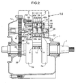
FIG. 2 is a sectional view taken along the line 2-2 inFIG. 1 . -
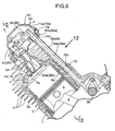
FIG. 3 is a view in the direction of thearrow 3 inFIG. 1 . -
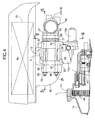
FIG. 4 is a sectional view taken along the line 4-4 inFIG. 1 . -
FIG. 5 is a sectional view taken along the line 5-5 inFIG. 4 . -
FIG. 6 is a sectional view taken along the line 6-6 inFIG. 4 . -
FIGS. 7A and 7B are views for explaining a procedure of mounting a carburetor. -
FIG. 8 is a view for explaining a procedure of mounting an air cleaner. -
FIG. 9 is an enlarged view of a first bank portion inFIG. 1 . -
FIG. 10 is a sectional view taken along the line 10-10 inFIG. 9 , and showing only the first bank. -
FIG. 11 is a view in the direction of thearrow 11 inFIG. 10 . -
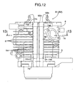
FIG. 12 is a view in the direction of thearrow 12 inFIG. 9 . -
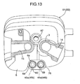
FIG. 13 is a sectional view taken along the line 13-13 inFIG. 12 . -
FIG. 14 is an enlarged view of a part indicated by thearrow 14 inFIG. 2 . -
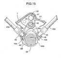
FIG. 15 is a sectional view taken along the line 15-15 inFIG. 14 . - An embodiment of the present invention will be described below with reference to the accompanying drawings.
- Firstly, as shown in
FIGS. 1 to 3 , the air-cooled general-purpose V-type engine includes: acrankcase 1; a first bank B1 and a second bank B2 which are arranged respectively on the left and right sides in a V-shape, and which are connected to an upper portion of thecrankcase 1; aninstallation flange 2 formed in a bottom portion of thecrankcase 1; and a starter device St provided in one side portion of the crankcase so as to be housed in a space below the first bank B1. - Each of the first and second banks B1 and B2 includes: a
cylinder block 3 which has acylinder bore 3a, and which is bolt-coupled to thecrankcase 1; acylinder head 4 which has acombustion chamber 4a leading to thecylinder bore 3a, and which is integrally connected to thecylinder block 3; and ahead cover 5 bolt-coupled to an end surface of thecylinder head 4. Each of the first and second banks B1 and B2 is integrally molded, and has a large number of air-cooling fins - A
single crankshaft 7 is rotatably supported by both of front and rear end walls, in the depth direction ofFIG. 1 , of thecrankcase 1.Pistons cylinder bores pistons crankpin 7p of thecrankshaft 7 via connectingrods end wall 1a of the front and rear end walls of thecrankcase 1 is detachably attached to a main body side of thecrankcase 1 while being capable of supporting a corresponding end portion of thecrankshaft 7. - As shown in
FIG. 1 , the first and second banks B1 and B2 are arranged in such a manner that the opening angle α between the banks B1 and B2, that is, the angle α formed by a cylinder center line A1 of the first bank B1 and a cylinder center line A2 of the second bank B2 becomes 90°. In addition,counterweights 7w are attached to thecrankshaft 7 on a side opposite to thecrankpin 7p. Thecounterweights 7w balance the inertia forces of thepistons 8 of the respective banks B1 and B2. - Moreover, the first and second banks B1 and B2 are arranged in such a manner that each of the cylinder center line A1 of the first bank B1 and the cylinder center line A2 of the second bank B2 passes a point P eccentric with respect to a rotational center A3 of the
crankshaft 7 to the side opposite to both of the banks B1 and B2. This arrangement makes it possible to widen avalley portion 11 defined between the first and second banks B1 and B2 while maintaining the opening angle α between the banks B1 and B2 at 90°. Thisvalley portion 11 houses the entirety of a carburetor C, which is one auxiliary machine of the V-type engine E, and part of an air cleaner Ac having acleaner element 10 installed therein. - As is clear from
FIG. 6 , the carburetor C is a twin carburetor including: a carburetormain body 12; and first andsecond intake paths main body 12 along with the arrangement direction of the first and second banks B1 and B2. Afloat chamber 12a and a fuel-cuttingelectromagnetic valve 12b are attached to a lower portion of the carburetormain body 12. - As shown in
FIGS. 1 ,4 , and5 , each of thecylinder heads combustion chamber 4a, anintake port 14 and anexhaust port 15 each opened to thecombustion chamber 4a. Opening end portions of the intake andexhaust ports combustion chamber 4a are formed respectively in anintake valve seat 80 and anexhaust valve seat 81, in eachcylinder head 4. Theintake valve seat 80 is formed to have a larger diameter than that of theexhaust valve seat 81. Moreover, these intake and exhaust valve seats 80, 81 as well as aplug mounting hole 87, into which anignition plug 23 is screwed, are arranged adjacent to one another so as to surround the center of thecombustion chamber 4a. - As shown in
FIGS. 9 to 11 , anintake valve exhaust valve cylinder head 4 of each of the banks B1 and B2. Theintake valve corresponding intake port 14 in association with the correspondingintake valve seat 80. Theexhaust valve corresponding exhaust port 15 in association with the correspondingexhaust valve seat 81. In addition, the ignition plug 23 with an electrode facing to thecombustion chamber 4a is screwed into thecylinder head 4. Here, eachintake valve corresponding exhaust valve - Each
intake valve corresponding exhaust valve intake valve exhaust valve corresponding cylinder bore 3a are set, as shown inFig. 10 , in the following manner. Specifically, these inclination angles θ1 and θ2 are set as large as possible within a range allowing cutting process performed on the intake and exhaust valve seats 80, 81 withrotary cutting tools - As shown in
FIGS. 1 ,4 ,5 , and6 , the first andsecond intake paths intake ports intake manifold 16 interposed in between. - Specifically, the
intake manifold 16 includes first andsecond conduit paths valley portion 11 so as to cause theintake ports second intake paths Individual flanges second conduit paths common flange 20 is formed at the upstream ends of the first andsecond conduit paths conduit paths individual flanges cylinder heads bolts thermal insulation plate 21, first and second mountingflanges flange 30 are jointly fastened to thecommon flange 20 with a plurality of bolts. The first and second mountingflanges The mounting flange 30 is formed on the outer periphery of an elbow-shapedair outlet pipe 22 in the air cleaner Ac. - Next, the above-described jointly-fastening structure will be described with reference to
FIGS. 4 to 8 . - The above-described jointly-fastening structure uses two
stud bolts tap bolts stud bolts common flange 20 of theintake manifold 16. A pair of upper and lower screw holes 27, 27 are provided in the other side portion of thecommon flange 20. The twotap bolts stud bolts flanges thermally insulation plate 21 and the carburetor C as well as the mountingflange 30 of the air cleaner Ac. Particularly, each of the first bolt holes 31', 31' of the first mountingflange 28 of the carburetor C is formed into a notch shape which opens to the outer side of theflange 28. - Note that, gaskets may be interposed in front and rear of the thermally 1
insulation plate 21 if necessary. - As shown in
FIGS. 1 to 3 ,9 ,14 and15 , a valve- operatingdevice 37 for opening and closing theintake valves exhaust valves crankcase 1 to thecylinder heads 4 of the respective banks B1 and B2. The valve- operatingdevice 37 includes acamshaft 38 and a timing transmission device 39 (seeFIG. 2 ). Thecamshaft 38 is rotatably supported directly above, and in parallel with, thecrankshaft 7, by both of the front and rear end walls of thecrankcase 1. Thetiming transmission device 39 reduces the rotational speed of thecrankshaft 7 by one half so as to transmit the reduced rotational speed to thecamshaft 38. Thetiming transmission 39 includes: a drivingtiming gear 40 which is fixed to thecrankshaft 7 at a position adjacent to the inner surface of the attachable/detachable end wall 1a of thecrankcase 1; and a driventiming gear 41 which is fixed secured to thecamshaft 38 and which meshes with thedriving timing gear 40. - An
intake cam 38i and anexhaust cam 38e are integrally formed on thecamshaft 38 as shown inFIGS. 14 and15 . Theintake cam 38i is connected to theintake valves intake cam followers intake push rods intake rocker arms FIGS. 1 and3 ). On the other hand, theexhaust cam 38e is connected to theexhaust valves exhaust cam followers exhaust push rods exhaust rocker arms intake push rod valley portion 11 side, of the corresponding one of the banks B1 and B2. - As is clear from
FIGS. 14 and15 , each of the first and secondintake cam followers exhaust cam followers boss portion 47 and aslipper portion 48. Theboss portions 47 are swingably supported on a singlecam follower shaft 46 which is attached to thecrankcase 1, at a position directly above, and in parallel with, thecamshaft 38. Each of theslipper portions 48 is in sliding contact with the corresponding one of thecams intake cam followers boss portions cam follower shaft 46, while theirslipper portions camshaft 38, which end portions protrude respectively in the opposite directions to each other in such a manner that theslipper portions intake cam 38i located in therebetween. On the other hand, also in the first and secondexhaust cam followers boss portions cam follower shaft 46, while theirslipper portions cam shaft 38, which end portions protrude respectively in the opposite directions to each other in such a manner that theslipper portions intake cam 38e located therein between. - One end portion of the
cam follower shaft 46 is supported by asupport hole 50 in thecrankcase 1, while the other end portion thereof is supported by abracket 51 securfixed to thecrankcase 1 with abolt 52. Thecam follower shaft 46 is provided with adistance collar 53 and acoil spring 54. Thedistance collar 53 abuts against an outer end surface of theboss portion 47 of one of the first and secondexhaust cam followers coil spring 54 is located between the pair of theboss portions intake cam followers boss portions exhaust cam followers distance collar 53 and thecoil spring 54, the first and second intake andexhaust cam followers cam follower shaft 46. The intake andexhaust cams exhaust cam followers crankpin 7p of thecrankshaft 7. - As shown in
FIG. 15 ,semispherical engaging recesses intake cam followers exhaust cam followers intake push rods recesses intake cam followers exhaust push rods recesses exhaust cam followers - As shown in
FIG. 3 , in the first and second banks B1 and B2, the first and secondintake rocker arms exhaust rocker arms corresponding cylinder heads 4 withrocker shafts exhaust rocker arms exhaust push rods exhaust push rods - Tubular rod covers 59, 60 (see
FIGS. 1 ,9 ,11 and12 ) which house the corresponding pair of the intake andexhaust push rods FIGS. 1 ,9 ,11 and12 ). - Specifically, upper-
portion support portion 74 and lower-portion support portion 75 are integrally formed in each of the banks B1 and B2 so as to protrude respectively from the upper and lower end portions of the bank to thevalley portion 11 between the banks B1 and B2. In each of the banks B 1 and B2, the upper-portion support portion 74 is provided with an upper-portion mounting holes portion support portion 75 is provided with a lower-portion mounting hole portion mounting hole 74h and the corresponding corresponding lower-portion mounting hole 75h are arranged on the same axis, and each upper-portion mounting hole 74h is formed to have a larger diameter than that of each lower-portion mounting hole 75h. In conjunction with this, each of theupper end portions portion mounting holes portion mounting holes portion mounting holes - In each of the banks B1 and B2, the valve springs 61, 62, the
intake rocker arms exhaust rocker arms chamber 63 defined between thecylinder head 4 and thehead cover 5 respectively. Each valve-operatingchamber 63 communicates with the inside of thecrankcase 1 through a hollow part of each of the rod covers 59, 60. - Moreover, as shown in
FIGS. 9 and12 , the air-coolingfins 6 are provided withU-shaped notches 6a which allow the rod covers 59, 60 to be arranged adjacent to the outer wall of the corresponding one of the banks B1 and B2. - Referring to
FIG. 2 again. Aflat portion 64 is formed on thecamshaft 38 so as to extend from a general surface of thecamshaft 38 to a base surface of theexhaust cam 38e. A decompressingmember 66 is pivotally and swingably supported on theflat portion 64 with apivot 65. The decompressingmember 66 is made of a steel plate, and includes a decompressingarm 66a and acentrifugal weight 66b. The decompressingarm 66a is located to the base surface side of theexhaust cam 38e so as to protrude its tip end from the base surface when the V-type engine E is stopped or started. Thecentrifugal weight 66b generates a centrifugal force for retreating the decompressingarm 66a from the base surface of theexhaust cam 38 when the V-type engine E is operated at a rotational speed higher than that during the idling of the V-type engine E.A return spring 69 for urging the decompressingarm 66a towards the base surface side of theexhaust cam 38 is connected to the decompressingmember 66. A decompressingdevice 70 is thus comprised of these above-described components. - At the time of starting of the V-type engine E, the decompressing
arm 66a occupies a position at which its tip end protrudes from the base surface of theexhaust cam 38e (see the chain line inFIG. 15 ). Accordingly, even in the compression stroke, the first and secondexhaust cam followers decompression arm 66a so as to slightly open theexhaust valves camshaft 38 is rotated at a predetermined rotational speed or more, thecentrifugal weight 66b swings outward in the radial direction against the set load of thereturn spring 69 due to the centrifugal force acting on thecentrifugal weight 66b. As a result, the decompressingarm 66a is retreated from the base surface of theexhaust cam 38e. - In the above-described configuration, all the intake and
exhaust push rods exhaust cam followers - Next, the operation of the embodiment will be described.
- As described above, the first and second banks B1 and B2 are arranged in such a manner that the opening angle α between the banks B1 and B2 becomes 90°. Meanwhile, the
counterweights 7w, which balance the inertia forces of thepistons 8 of the respective banks B1 and B2, are attached to thecrankshaft 7 on the side opposite to thecrankpin 7p. Accordingly, as is well known, the inertia force at the top dead center and the bottom dead center of thepiston 8 in each of the banks B1 and B2 balances the centrifugal force of thecounterweights 7w. Therefore, it is possible to balance the primary inertia force of the V-type engine E without providing a special primary balancer mechanism. - Moreover, the first and second banks B1 and B2 are arranged in such a manner that each of the cylinder
center line A 1 of the first bank B1 and the cylinder center line A2 of the second bank B2 are arranged to passes the point P eccentric from with respect to the rotational center A3 of thecrankshaft 7 to the side opposite to both of the banks B1 and B2. This arrangement allows thevalley portion 11 defined between the first and second banks B1 and B2 to be widened with the opening angle α between the banks B1 and B2 being maintained at 90°. Accordingly, since the entire carburetor C, which is one auxiliary machine of the V-type engine E, and also part of the air cleaner Ac can be housed with a margin in thevalley portion 11, a compact V-type engine E having a small overall height can be provided. - In addition, in this structure, the carburetor C is the twin carburetor including the first and
second intake paths intake ports conduit paths - Moreover, the pair of
conduit paths intake manifold 16 along with thecommon flange 20 formed at the upstream ends of theconduit paths conduit paths common flange 20 to the downstream end of the twin carburetor C simplifies the structure of the intake system of the V-type engine E. As a result, a favorable assemblability of the intake system is achieved. - The
thermal insulation plate 21, the carburetor C, and the air cleaner Ac are mounted to thecommon flange 20 of theintake manifold 16 in the following manner. Firstly, as shown inFIG. 7A , the first bolt holes 31, 31 of the thermally insulatingthermal insulation plate 21 are fitted respectively onto the twostud bolts common flange 20. Subsequently, the notched first bolt holes 31', 31' of the first mountingflange 28 of the carburetor C are engaged with thestud bolts FIG. 7A ). Thereafter, while the entire carburetor C is moved toward thethermal insulation plate 21, the first bolt holes 31, 31 of the second mountingflange 29 are fitted onto thestud bolts 25, 25 (seeFIG. 8 ). In this way, the carburetor C having a relatively large length in the axial direction can be set at a predetermined fitting position with respect to thestud bolts stud bolts FIG. 4 , a bulgedportion 1s of thecrankcase 1 exists outward of the outer end portions of thestud bolts timing gear 41 having a large diameter. The bulgedportion 1s interferes with the reception of thefloat chamber 12a and the fuel-cuttingelectromagnetic valve 12b of the carburetor C to a space outward of the outer end portions of thestud bolts portion 1s is very effective. - Next, as shown in
FIG. 8 , the first bolt holes 31, 31 of the mountingflange 30 of the air cleaner Ac are fitted respectively onto thestud bolts nuts stud bolts tap bolts common flange 20. When thetap bolts tap bolts tap bolt 26 is thin, the space for moving thetap bolt 26 can be easily secured in general. - In the above-described structure, the using of the two
stud bolts thermal insulation plate 21, the carburetor C, and the air cleaner Ac are fitted onto thestud bolts thermal insulation plate 21, the carburetor C, and the air cleaner Ac aroundabout any one of thestud bolts tap bolts tap bolts - In addition, by use of the
tap bolts flanges common flange 20 with thestud bolts tap bolts - The carburetor C and the air cleaner Ac can be dismounted from the
common flange 20 by conversely performing the above-described operation procedures. - The valve-operating
device 37 has the following structure. Each pair of the intake andexhaust rocker arms exhaust push rods exhaust push rods exhaust push rods portion support portion 74 and the lower-portion support portion 75 protruding toward thevalley portion 11 respectively from the upper and lower end portions of the corresponding one of the banks B1 and B2. In addition, the air-coolingfins 6 of each of the banks B1 and B2 are provided with thenotches 6a which allow the rod covers 59, 60 to be arranged adjacent to the outer wall of the corresponding one of the banks B1 and B2. With this structure, most parts of the intake andexhaust push rods - Each pair of the intake and
exhaust push rods portion support portions valley portion 11 respectively from the upper and lower end portions of the corresponding one of the banks B1 and B2. Moreover, since the rod covers 59, 60 are disposed, on thevalley portion 11 side, between the first and second banks B1 and B2, the rod covers 59, 60 are protected by the banks B1 and B2 from being brought into contact with foreign objects. - In each of the banks B1 and B2, the corresponding pair of the intake and
exhaust rocker arms exhaust push rods exhaust push rods fins 6 of each of the banks B1 and B2 are provided with thenotches 6a which allow the rod covers 59, 60, which house each pair of the intake andexhaust push rods notch 6a, and thereby to keep, at the minimum level, a reduction in heat radiating function of the air-coolingfins 6 due to the formation of thenotches 6a. - In addition, each of the
cam followers boss portion 47 and theslipper portion 48. Eachboss portion 47 is swingably supported on the singlecam follower shaft 46, which is attached to thecrankcase 1, at a position directly above, and in parallel with, thecamshaft 38. Eachslipper portion 48 is in sliding contact with the corresponding one of thecams intake cam followers boss portions cam follower shaft 46, while theirslipper portions camshaft 38, which end portions protrude respectively in the opposite directions to each other in such a manner that theslipper portions intake cam 38i located there between. In addition, in the first and secondexhaust cam followers boss portions cam follower shaft 46, while theirslipper portions camshaft 38, which end portions protrude respectively in the opposite directions to each other in such a manner that theslipper portions exhaust cam 38e located in therebetween. Accordingly, the first intake andexhaust cam followers exhaust cam followers single camshaft 38 and the singlecam follower shaft 46. This concentrated arrangement makes it possible to achieve the compact valve-operatingdevice 37, and in particular, to shorten thecamshaft 38. Furthermore, the following effect is provided by the structure in which, in each of the pair of the first and secondintake cam followers exhaust cam followers slipper portions cam camshaft 38, which end portions protrude respectively in the opposite directions to each other in such a manner that theslipper portions slipper portions cam - In addition, the first and second intake and
exhaust cam followers exhaust cams crankpin 7p of thecrankshaft 7, achieving the compact valve operating-device 37. Accordingly, while thecrankshaft 7 is rotated, the periphery of the intake andexhaust cams crankpin 7p. - Moreover, the
flat portion 64 is formed on thecamshaft 38 so as to extend from the general surface of thecamshaft 38 to the base surface of theexhaust cam 38e. Then, the decompressingmember 66 is swingably supported around an axis on theflat portion 64. The decompressingmember 66 includes the decompressingarm 66a and thecentrifugal weight 66b. When the V-type engine E is stopped or started stopped or started, the decompressingarm 66a is located to its operating position on the base surface side of theexhaust cam 38e so as to protrudes its tip end from the base surface so as to, thereby lifting the first and secondexhaust cam followers centrifugal weight 66b generates a centrifugal force for retreating the decompressingarm 66a from the base surface of theexhaust cam 38e when the V-type engine E is operated at a rotational speed higher than that during the idling of the V-type engine E. In addition, thereturn spring 69 for urging the decompressingarm 66a toward the operating position is connected to the decompressingmember 66. This structure provides the following effect in association with the aforementioned structure of the first and secondexhaust cam followers camshaft 38, which end portions protrude respectively in the opposite directions to each other in such a manner that the slipper portions face each other across the exhaust cam located in therebetween. Specifically, at the operating position of the decompressingmember 66, only slight protrusion of the tip end portion of the decompressingarm 66a toward theexhaust cam 38e makes it possible to provide very slightly lift to the first and secondexhaust cam followers exhaust cam followers arm 66a toward theexhaust cam 38e has the following meaning. Specifically, this makes it possible to achieve a compactsingle decompressing device 70 shared by both the banks B1 and B2, and also to improve the durability of theexhaust cam 38e and theexhaust cam followers exhaust cam 38e due to the formation of theflat portion 64. - Furthermore, the
flat portion 64 is formed on thecamshaft 38 so as to extend from the general surface of thecamshaft 38 to the base surface of theexhaust cam 38e. The decompressingarm 66a of the decompressingmember 66, which is pivotally supported around an axis on theflat portion 64, is caused to protrude toward the base surface of theexhaust cam 38e when the V-type engine E is stopped or started. This structure eliminates the need to cause theslipper portions exhaust cam followers exhaust cam 38e. As a result, it is possible to achieve the decompressing operation performed at the time of start of the V-type engine E while keeping the compactness of the valve-operatingdevice 37. - Although, the embodiment of the present invention has been described so far, various modifications in design may be made on the present invention without departing from the scope of the present invention.
Claims (3)
- A V-type engine (E) comprising:first and second banks (B1, B2) each of which includes a cylinder bore (3 a) therein, and which are arranged in a V-shape so as to define a valley portion therein between;a crankcase (1) with which the first and second banks (B1, B2) are continuously formed;a crankshaft (7) supported by the crankcase;an air-cooling fin (6) which protrudes on an outer wall of each of the banks;intake (35a, 35b) and exhaust (36a, 36b) valves which are arranged in a V-shape in a head portion (4) of each of the banks (B1, B2); anda valve-operating device which drives the intake (35a, 35b) and exhaust (36a, 36b) valves to be opened and closed,the valve-operating device and which includes:a camshaft (38) having intake and exhaust cams, and being disposed above the crankshaft (7) and driven by the crankshaft,first intake and exhaust cam followers (42a, 43a) and second intake and exhaust cam followers (42b, 43b) being moved up and down by intake and exhaust cams (38i, 38e) of the camshaft (38) respectively,first intake and exhaust push rods (44a, 45a) and second intake and exhaust push rods (44b, 45b), the first intake and exhaust push rods (44a, 45a) having lower ends which are operatively connected respectively to the first intake and exhaust cam followers (42a, 43a), and being disposed on the valley portion side of the first bank (B1), the second intake and exhaust push rods (44b, 45b) having lower ends which are operatively connected respectively to the second intake and exhaust cam followers (42b, 43b), and being disposed on the valley portion side of the second bank (B2), andfirst intake and exhaust rocker arms (7 1 a, 72a) and second intake and exhaust rocker arms (71 b, 72b), the first intake and exhaust rocker arms (71a, 72b) operatively connecting the upper ends of the first intake and exhaust push rods (44a, 45a) respectively to the intake and exhaust valves (35a, 36a) of the first bank (B1), the second intake and exhaust rocker arms (7 1 b, 72b) operatively connecting the upper ends of the seconds intake and exhaust push rods (44b, 45b) respectively to the intake and exhaust valves (35b, 36b) of the second bank (B1), whereinthe intake and exhaust rocker arms (71a, 71b, 72a, 72b) in each bank (B1, B2) are arranged in a substantially inverted-V-shape in a plan view, so that side end portions of the intake and exhaust rocker arms (71a, 71b, 72a, 72b) on the side of the corresponding intake and exhaust push rods (44a, 44b, 45a, 45b) are positioned adjacent to each other, thereby intake and exhaust push rods are positioned adjacent to each other,each of the cam followers (42a, 42b, 43a, 43b) is comprised of a boss portion (47) swingably supported on a single cam follower shaft (46) supported by the crankcase (1) at a position directly above and in parallel with the camshaft (38), and a slipper portion (48) being in sliding contact with a corresponding one of the intake and exhaust cams (38e, 38i),the boss portion (47) of the first and second intake cam followers (42a, 42b( abut against each other side by side on the cam follower shaft (46), while their slipper portions (48) have end portions at one end along an axial direction of the camshaft (38) which protrude respectively in opposite directions to each other in such a manner that the slipper portions (48) face each other across the intake cam (38i) located therebetween,the boss portions (47) of the first and second exhaust cam followers (43a, 43b) abut against each other side by side on the cam follower shaft (46), while their slipper portions (48) have end portions at one end along the axial direction of the camshaft (38), which protrude respectively in the opposite directions to each other in such a manner that the slipper portions (48) face each other across the exhaust cam (38e) located therebetween,the first and second intake cam followers (42a, 42b) and the first and second exhaust cam followers (43a, 43b) are arranged adjacent to one another on an intermediate portion of the cam follower shaft (46), which is supported, at opposite end portions thereof, by the crankcase (1), andcorresponding to the cam followers (42a, 43a, 42b, 43b), the intake and exhaust cams (38i, 38e) are arranged adjacent to each other.
- The V-type engine according to claim 1, wherein the first and second intake and exhaust cam followers (42a, 43a, 42b, 43b) of both of the banks (B1, B2) as well as the intake and exhaust cams (38i, 38e) are mostly placed within a space between planes extended respectively from opposite end surfaces of a crankpin (7p) of the crankshaft.
- The V-type engine according to any one of claims 1 and 2 further comprising:a flat portion (64) formed in the camshaft (38) so as to extend from an outer peripheral face of the camshaft (38) to a base surface of the exhaust cam (38e);a decompressing member (70) being swingably axis-supported on the flat portion (64), and includinga decompressing arm (66a) which is located, over a period between instants when the V-type engine stops and starts, to its operating position on the base surface side of the exhaust cam (38e) and protrudes its tip end from the base surface so as to lifting the first and second exhaust cam followers (42a, 43a, 42b, 43b) in the compression stroke of the V-type engine, anda centrifugal weight (66b) which generates a centrifugal force for retreating the decompressing arm from the base surface when the V-type engine is operated at a rotational speed higher than that during the idling of the V-type engine; anda return spring for urging the decompressing arm (66a) toward the operating position, the return spring being connected to the decompressing member (66).
Applications Claiming Priority (1)
| Application Number | Priority Date | Filing Date | Title |
|---|---|---|---|
| JP2007120058A JP4739277B2 (en) | 2007-04-27 | 2007-04-27 | V type engine |
Publications (2)
| Publication Number | Publication Date |
|---|---|
| EP1985812A1 true EP1985812A1 (en) | 2008-10-29 |
| EP1985812B1 EP1985812B1 (en) | 2010-03-24 |
Family
ID=39645376
Family Applications (1)
| Application Number | Title | Priority Date | Filing Date |
|---|---|---|---|
| EP08251514A Not-in-force EP1985812B1 (en) | 2007-04-27 | 2008-04-24 | V-type engine |
Country Status (6)
| Country | Link |
|---|---|
| US (1) | US7918199B2 (en) |
| EP (1) | EP1985812B1 (en) |
| JP (1) | JP4739277B2 (en) |
| CN (1) | CN101294503B (en) |
| DE (1) | DE602008000851D1 (en) |
| ES (1) | ES2341396T3 (en) |
Cited By (1)
| Publication number | Priority date | Publication date | Assignee | Title |
|---|---|---|---|---|
| WO2022262905A1 (en) * | 2021-06-16 | 2022-12-22 | Neander Motors Aktiengesellschaft | Reciprocating piston engine |
Families Citing this family (8)
| Publication number | Priority date | Publication date | Assignee | Title |
|---|---|---|---|---|
| JP5909322B2 (en) * | 2011-04-20 | 2016-04-26 | 本田技研工業株式会社 | Oil passage structure of internal combustion engine with variable valve mechanism |
| JP6089575B2 (en) * | 2012-10-18 | 2017-03-08 | スズキ株式会社 | Decompression parts of decompression equipment |
| WO2014071817A1 (en) * | 2012-11-06 | 2014-05-15 | Niu Gangxue | Decompression device for internal combustion engine |
| US8931444B2 (en) | 2012-11-20 | 2015-01-13 | Ford Global Technologies, Llc | Head packaging for cylinder deactivation |
| CN103557038A (en) * | 2013-11-12 | 2014-02-05 | 隆鑫通用动力股份有限公司 | Valve rocker mounting structure and gasoline engine thereof |
| USD733762S1 (en) * | 2014-01-17 | 2015-07-07 | Kohler Co. | Engine |
| CN109973168B (en) * | 2019-03-27 | 2020-11-10 | 大连理工大学 | A multi-mode fully variable mechanism |
| US11719182B1 (en) * | 2022-08-17 | 2023-08-08 | Deltahawk Engines, Inc. | Engine cylinder with liner |
Citations (7)
| Publication number | Priority date | Publication date | Assignee | Title |
|---|---|---|---|---|
| JPH03107515A (en) | 1989-09-20 | 1991-05-07 | Honda Motor Co Ltd | V-type engine |
| US5253621A (en) * | 1992-08-14 | 1993-10-19 | Group Lotus Plc | Valve control means |
| EP0637682A1 (en) * | 1993-08-04 | 1995-02-08 | Mercedes-Benz Ag | Multicylinder internal combustion engine with V-configuration arranged cylinders |
| US20020026918A1 (en) * | 2000-09-02 | 2002-03-07 | Bernhard Durr | Valve drive mechanism for an internal combustion engine |
| EP1318277A2 (en) * | 2001-12-07 | 2003-06-11 | Honda Giken Kogyo Kabushiki Kaisha | OHV engine |
| US20050034698A1 (en) * | 2003-07-25 | 2005-02-17 | Minoru Matsuda | Valve train for OHV engine |
| US20050061281A1 (en) * | 2003-09-22 | 2005-03-24 | Klotz James R. | Valve lifter for internal combustion engine |
Family Cites Families (16)
| Publication number | Priority date | Publication date | Assignee | Title |
|---|---|---|---|---|
| US1524150A (en) * | 1919-02-06 | 1925-01-27 | Willys Overland Co | Valve-operating mechanism |
| US2769434A (en) * | 1953-11-04 | 1956-11-06 | Studebaker Packard Corp | Overhead valve arrangement for engines |
| JPS60192207A (en) * | 1984-03-13 | 1985-09-30 | Nittan Co Ltd | Detecting device for preventing disaster |
| JPS6117147A (en) * | 1984-07-04 | 1986-01-25 | Nec Corp | Pattern checking method of photomask |
| JPS63246404A (en) * | 1987-04-01 | 1988-10-13 | Yamaha Motor Co Ltd | Pressure reducing device for internal combustion engine |
| JP2000297654A (en) * | 1999-04-12 | 2000-10-24 | Suzuki Motor Corp | 4 cycle engine |
| US6257187B1 (en) * | 1999-05-06 | 2001-07-10 | Caterpillar Inc. | Pivot shaft for an internal combustion engine |
| JP2001107708A (en) * | 1999-10-12 | 2001-04-17 | Honda Motor Co Ltd | Valve train for overhead valve type internal combustion engine |
| JP3547382B2 (en) * | 2000-09-08 | 2004-07-28 | 川崎重工業株式会社 | Overhead valve type V2 engine |
| DE10047255C2 (en) * | 2000-09-23 | 2003-03-06 | Porsche Ag | Automatic decompression device for valve-controlled internal combustion engines |
| JP2002349227A (en) * | 2001-05-25 | 2002-12-04 | Ishikawajima Shibaura Mach Co Ltd | Four cycle engine |
| DE10253231B3 (en) * | 2002-11-15 | 2004-02-12 | Dr.Ing.H.C. F. Porsche Ag | Automatic decompression device for valve-controlled engine has decompression lever in form of arc-shaped element with both ends on camshaft |
| JP2005002809A (en) * | 2003-06-10 | 2005-01-06 | Fuji Heavy Ind Ltd | Sheet metal rocker arm manufacturing method |
| JP2005002810A (en) * | 2003-06-10 | 2005-01-06 | Fuji Heavy Ind Ltd | Sheet metal rocker arm manufacturing method |
| JP4430658B2 (en) * | 2006-12-22 | 2010-03-10 | 本田技研工業株式会社 | V type engine |
| JP4792423B2 (en) * | 2007-04-27 | 2011-10-12 | 本田技研工業株式会社 | Air-cooled V-type engine |
-
2007
- 2007-04-27 JP JP2007120058A patent/JP4739277B2/en not_active Expired - Fee Related
-
2008
- 2008-04-24 US US12/109,044 patent/US7918199B2/en active Active
- 2008-04-24 EP EP08251514A patent/EP1985812B1/en not_active Not-in-force
- 2008-04-24 ES ES08251514T patent/ES2341396T3/en active Active
- 2008-04-24 CN CN2008100923552A patent/CN101294503B/en not_active Expired - Fee Related
- 2008-04-24 DE DE602008000851T patent/DE602008000851D1/en active Active
Patent Citations (7)
| Publication number | Priority date | Publication date | Assignee | Title |
|---|---|---|---|---|
| JPH03107515A (en) | 1989-09-20 | 1991-05-07 | Honda Motor Co Ltd | V-type engine |
| US5253621A (en) * | 1992-08-14 | 1993-10-19 | Group Lotus Plc | Valve control means |
| EP0637682A1 (en) * | 1993-08-04 | 1995-02-08 | Mercedes-Benz Ag | Multicylinder internal combustion engine with V-configuration arranged cylinders |
| US20020026918A1 (en) * | 2000-09-02 | 2002-03-07 | Bernhard Durr | Valve drive mechanism for an internal combustion engine |
| EP1318277A2 (en) * | 2001-12-07 | 2003-06-11 | Honda Giken Kogyo Kabushiki Kaisha | OHV engine |
| US20050034698A1 (en) * | 2003-07-25 | 2005-02-17 | Minoru Matsuda | Valve train for OHV engine |
| US20050061281A1 (en) * | 2003-09-22 | 2005-03-24 | Klotz James R. | Valve lifter for internal combustion engine |
Cited By (1)
| Publication number | Priority date | Publication date | Assignee | Title |
|---|---|---|---|---|
| WO2022262905A1 (en) * | 2021-06-16 | 2022-12-22 | Neander Motors Aktiengesellschaft | Reciprocating piston engine |
Also Published As
| Publication number | Publication date |
|---|---|
| CN101294503B (en) | 2011-05-18 |
| CN101294503A (en) | 2008-10-29 |
| US7918199B2 (en) | 2011-04-05 |
| ES2341396T3 (en) | 2010-06-18 |
| EP1985812B1 (en) | 2010-03-24 |
| JP2008274864A (en) | 2008-11-13 |
| US20080264361A1 (en) | 2008-10-30 |
| DE602008000851D1 (en) | 2010-05-06 |
| JP4739277B2 (en) | 2011-08-03 |
Similar Documents
| Publication | Publication Date | Title |
|---|---|---|
| US7918199B2 (en) | V-type engine | |
| US7690346B2 (en) | Carburetor mounting structure | |
| CA2476240C (en) | Variable compression ratio engine | |
| US8276560B2 (en) | V-type engine | |
| US8136501B2 (en) | Variable stroke engine | |
| JP2000120422A (en) | Engine camshaft lubrication structure | |
| JP4025622B2 (en) | General-purpose single cylinder engine | |
| EP1439286B1 (en) | Internal combustion engine with decompression device | |
| US7305938B2 (en) | Stroke-variable engine | |
| US6857408B2 (en) | Internal combustion engine provided with decompressing mechanism | |
| JP4792423B2 (en) | Air-cooled V-type engine | |
| JP4647860B2 (en) | Inclined cylinder type general-purpose four-cycle engine | |
| WO2008098433A1 (en) | An overhead camshaft engine | |
| JP4063960B2 (en) | Valve mechanism of multi-cylinder engine | |
| JP2003314237A (en) | Engine | |
| JP4063682B2 (en) | Multi-cylinder internal combustion engine | |
| JP3887210B2 (en) | Engine valve gear | |
| JP2003120219A (en) | Valve train for air-cooled two-cylinder engine | |
| JPH05133207A (en) | Valve system for five-valve engine | |
| JP2004225535A (en) | Internal combustion engine | |
| JP2004225536A (en) | Internal combustion engine | |
| JP2005330946A (en) | Multi-cylinder engine |
Legal Events
| Date | Code | Title | Description |
|---|---|---|---|
| PUAI | Public reference made under article 153(3) epc to a published international application that has entered the european phase |
Free format text: ORIGINAL CODE: 0009012 |
|
| 17P | Request for examination filed |
Effective date: 20080513 |
|
| AK | Designated contracting states |
Kind code of ref document: A1 Designated state(s): AT BE BG CH CY CZ DE DK EE ES FI FR GB GR HR HU IE IS IT LI LT LU LV MC MT NL NO PL PT RO SE SI SK TR |
|
| AX | Request for extension of the european patent |
Extension state: AL BA MK RS |
|
| 17Q | First examination report despatched |
Effective date: 20090218 |
|
| AKX | Designation fees paid |
Designated state(s): DE ES FR GB IT |
|
| GRAP | Despatch of communication of intention to grant a patent |
Free format text: ORIGINAL CODE: EPIDOSNIGR1 |
|
| GRAS | Grant fee paid |
Free format text: ORIGINAL CODE: EPIDOSNIGR3 |
|
| GRAA | (expected) grant |
Free format text: ORIGINAL CODE: 0009210 |
|
| AK | Designated contracting states |
Kind code of ref document: B1 Designated state(s): DE ES FR GB IT |
|
| REG | Reference to a national code |
Ref country code: GB Ref legal event code: FG4D |
|
| REF | Corresponds to: |
Ref document number: 602008000851 Country of ref document: DE Date of ref document: 20100506 Kind code of ref document: P |
|
| REG | Reference to a national code |
Ref country code: ES Ref legal event code: FG2A Ref document number: 2341396 Country of ref document: ES Kind code of ref document: T3 |
|
| PLBE | No opposition filed within time limit |
Free format text: ORIGINAL CODE: 0009261 |
|
| STAA | Information on the status of an ep patent application or granted ep patent |
Free format text: STATUS: NO OPPOSITION FILED WITHIN TIME LIMIT |
|
| 26N | No opposition filed |
Effective date: 20101228 |
|
| REG | Reference to a national code |
Ref country code: FR Ref legal event code: PLFP Year of fee payment: 9 |
|
| REG | Reference to a national code |
Ref country code: FR Ref legal event code: PLFP Year of fee payment: 10 |
|
| REG | Reference to a national code |
Ref country code: FR Ref legal event code: PLFP Year of fee payment: 11 |
|
| PGFP | Annual fee paid to national office [announced via postgrant information from national office to epo] |
Ref country code: GR Payment date: 20190619 Year of fee payment: 11 Ref country code: ES Payment date: 20190503 Year of fee payment: 12 |
|
| REG | Reference to a national code |
Ref country code: DE Ref legal event code: R084 Ref document number: 602008000851 Country of ref document: DE |
|
| REG | Reference to a national code |
Ref country code: GB Ref legal event code: 746 Effective date: 20191218 |
|
| PGFP | Annual fee paid to national office [announced via postgrant information from national office to epo] |
Ref country code: FR Payment date: 20210310 Year of fee payment: 14 |
|
| PGFP | Annual fee paid to national office [announced via postgrant information from national office to epo] |
Ref country code: GB Payment date: 20210331 Year of fee payment: 14 |
|
| REG | Reference to a national code |
Ref country code: ES Ref legal event code: FD2A Effective date: 20210906 |
|
| PG25 | Lapsed in a contracting state [announced via postgrant information from national office to epo] |
Ref country code: IT Free format text: LAPSE BECAUSE OF NON-PAYMENT OF DUE FEES Effective date: 20200424 |
|
| PG25 | Lapsed in a contracting state [announced via postgrant information from national office to epo] |
Ref country code: ES Free format text: LAPSE BECAUSE OF NON-PAYMENT OF DUE FEES Effective date: 20200425 |
|
| GBPC | Gb: european patent ceased through non-payment of renewal fee |
Effective date: 20220424 |
|
| PG25 | Lapsed in a contracting state [announced via postgrant information from national office to epo] |
Ref country code: GB Free format text: LAPSE BECAUSE OF NON-PAYMENT OF DUE FEES Effective date: 20220424 Ref country code: FR Free format text: LAPSE BECAUSE OF NON-PAYMENT OF DUE FEES Effective date: 20220430 |
|
| PGFP | Annual fee paid to national office [announced via postgrant information from national office to epo] |
Ref country code: DE Payment date: 20230228 Year of fee payment: 16 |
|
| REG | Reference to a national code |
Ref country code: DE Ref legal event code: R119 Ref document number: 602008000851 Country of ref document: DE |
|
| PG25 | Lapsed in a contracting state [announced via postgrant information from national office to epo] |
Ref country code: DE Free format text: LAPSE BECAUSE OF NON-PAYMENT OF DUE FEES Effective date: 20241105 |
|
| PG25 | Lapsed in a contracting state [announced via postgrant information from national office to epo] |
Ref country code: DE Free format text: LAPSE BECAUSE OF NON-PAYMENT OF DUE FEES Effective date: 20241105 |