EP1985367B1 - Haltegestell für Dosierungseinheiten mit aktiver Benutzeranleitungsvorrichtung - Google Patents
Haltegestell für Dosierungseinheiten mit aktiver Benutzeranleitungsvorrichtung Download PDFInfo
- Publication number
- EP1985367B1 EP1985367B1 EP07106744A EP07106744A EP1985367B1 EP 1985367 B1 EP1985367 B1 EP 1985367B1 EP 07106744 A EP07106744 A EP 07106744A EP 07106744 A EP07106744 A EP 07106744A EP 1985367 B1 EP1985367 B1 EP 1985367B1
- Authority
- EP
- European Patent Office
- Prior art keywords
- dosage
- unit
- rack
- holding rack
- dispensing
- Prior art date
- Legal status (The legal status is an assumption and is not a legal conclusion. Google has not performed a legal analysis and makes no representation as to the accuracy of the status listed.)
- Not-in-force
Links
Images


Classifications
-
- B—PERFORMING OPERATIONS; TRANSPORTING
- B01—PHYSICAL OR CHEMICAL PROCESSES OR APPARATUS IN GENERAL
- B01L—CHEMICAL OR PHYSICAL LABORATORY APPARATUS FOR GENERAL USE
- B01L3/00—Containers or dishes for laboratory use, e.g. laboratory glassware; Droppers
- B01L3/02—Burettes; Pipettes
- B01L3/0289—Apparatus for withdrawing or distributing predetermined quantities of fluid
-
- G—PHYSICS
- G06—COMPUTING OR CALCULATING; COUNTING
- G06Q—INFORMATION AND COMMUNICATION TECHNOLOGY [ICT] SPECIALLY ADAPTED FOR ADMINISTRATIVE, COMMERCIAL, FINANCIAL, MANAGERIAL OR SUPERVISORY PURPOSES; SYSTEMS OR METHODS SPECIALLY ADAPTED FOR ADMINISTRATIVE, COMMERCIAL, FINANCIAL, MANAGERIAL OR SUPERVISORY PURPOSES, NOT OTHERWISE PROVIDED FOR
- G06Q10/00—Administration; Management
- G06Q10/08—Logistics, e.g. warehousing, loading or distribution; Inventory or stock management
- G06Q10/087—Inventory or stock management, e.g. order filling, procurement or balancing against orders
-
- B—PERFORMING OPERATIONS; TRANSPORTING
- B01—PHYSICAL OR CHEMICAL PROCESSES OR APPARATUS IN GENERAL
- B01L—CHEMICAL OR PHYSICAL LABORATORY APPARATUS FOR GENERAL USE
- B01L2200/00—Solutions for specific problems relating to chemical or physical laboratory apparatus
- B01L2200/06—Fluid handling related problems
- B01L2200/0647—Handling flowable solids, e.g. microscopic beads, cells, particles
- B01L2200/0657—Pipetting powder
-
- B—PERFORMING OPERATIONS; TRANSPORTING
- B01—PHYSICAL OR CHEMICAL PROCESSES OR APPARATUS IN GENERAL
- B01L—CHEMICAL OR PHYSICAL LABORATORY APPARATUS FOR GENERAL USE
- B01L2200/00—Solutions for specific problems relating to chemical or physical laboratory apparatus
- B01L2200/14—Process control and prevention of errors
-
- B—PERFORMING OPERATIONS; TRANSPORTING
- B01—PHYSICAL OR CHEMICAL PROCESSES OR APPARATUS IN GENERAL
- B01L—CHEMICAL OR PHYSICAL LABORATORY APPARATUS FOR GENERAL USE
- B01L2200/00—Solutions for specific problems relating to chemical or physical laboratory apparatus
- B01L2200/16—Reagents, handling or storing thereof
-
- B—PERFORMING OPERATIONS; TRANSPORTING
- B01—PHYSICAL OR CHEMICAL PROCESSES OR APPARATUS IN GENERAL
- B01L—CHEMICAL OR PHYSICAL LABORATORY APPARATUS FOR GENERAL USE
- B01L2300/00—Additional constructional details
- B01L2300/02—Identification, exchange or storage of information
- B01L2300/021—Identification, e.g. bar codes
- B01L2300/022—Transponder chips
-
- B—PERFORMING OPERATIONS; TRANSPORTING
- B01—PHYSICAL OR CHEMICAL PROCESSES OR APPARATUS IN GENERAL
- B01L—CHEMICAL OR PHYSICAL LABORATORY APPARATUS FOR GENERAL USE
- B01L2300/00—Additional constructional details
- B01L2300/02—Identification, exchange or storage of information
- B01L2300/023—Sending and receiving of information, e.g. using bluetooth
-
- B—PERFORMING OPERATIONS; TRANSPORTING
- B01—PHYSICAL OR CHEMICAL PROCESSES OR APPARATUS IN GENERAL
- B01L—CHEMICAL OR PHYSICAL LABORATORY APPARATUS FOR GENERAL USE
- B01L9/00—Supporting devices; Holding devices
Definitions
- the present invention relates to a laboratory setup with a holding rack for dosage units (i.e. substance receptacles with attached dispensing heads for pulverous substances) which is equipped with an active user-guiding means that directs the user in a sequence of taking out and returning the different dosage units that are seated in the rack, e.g. for preparing a mixture, where it is of critical importance that none of the dosage units are accidentally either taken out more than once or overlooked in the preparation of the mixture.
- dosage units i.e. substance receptacles with attached dispensing heads for pulverous substances
- an active user-guiding means that directs the user in a sequence of taking out and returning the different dosage units that are seated in the rack, e.g. for preparing a mixture, where it is of critical importance that none of the dosage units are accidentally either taken out more than once or overlooked in the preparation of the mixture.
- the application envisioned for the present invention is mainly for manually performed procedures in which an operator takes each individual dosage unit out of a holding rack and places it into a dispensing setup, typically a dosage-dispensing setup that couples to a shutter- and/or feeder element in the dispensing head of the dosage unit to deliver a measured quantity of powder from the dosage unit into a receiving container.
- a dispensing setup typically a dosage-dispensing setup that couples to a shutter- and/or feeder element in the dispensing head of the dosage unit to deliver a measured quantity of powder from the dosage unit into a receiving container.
- the manual process of taking dosage units from the rack and placing them in the dispensing setup involves the risk of operator errors for example if a plurality of different powders are to be dispensed sequentially into the same receiving container. If, for example, the user accidentally dispenses a dose of powder twice from the same container, the resulting mixture in the receiving container will have the wrong mix ratio.
- the process of mixing substances in this manner is used for example for standards for the calibration of HPLC (High Performance Liquid Chromatography) instruments which has to be performed in accordance with regulatory requirements.
- HPLC High Performance Liquid Chromatography
- Such standards are mixtures of different pulverous substances which, as a rule, are mixed together and solved in an appropriate solvent right before they are used, because if the individual components were kept in a mixed state and/or solved over a longer storage time period a destruction reaction could take place.
- this invention has the objective to provide a laboratory setup with a holding rack for dosage units which has a degree of intelligence which ensures that each dosage component is dispensed into the target batch only once and no dosage component is accidentally omitted from the target batch.
- a laboratory setup comprising a laboratory balance with a dosage-dispensing device, a processor unit and a holding rack with dosage units, wherein a dosage unit can occupy an individual position or compartment of the holding rack.
- the laboratory setup is equipped with a respective communication path or interface connection between the processor unit and the holding rack.
- the holding rack is equipped with an active user-guiding means which is controlled by the processor based on a procedure which is stored in a memory unit of the processor unit, to direct the user in taking out and returning the different dosage units that are seated in said holding rack.
- the term "dosage unit” in the present context means a dispensing head with a supply receptacle for a pulverous substance, In the dispensing position of the dosage unit, the dispensing head is arranged below the supply receptacle.
- a dosage-dispensing device i.e. an actuator device which by means of a coupling engages and actuates a discharge control element of the dispensing head, whereby substance is dispensed from a discharge orifice of the dispensing head into a receiving container (also referred to as target container) which is set up below the dosage unit, for example on the weighing pan of an analytical balance.
- the weighing signal from the balance is fed back to a processor unit or computer which controls the actuator device which through the aforementioned coupling actuates the discharge control device to control the rate of substance delivery and to stop the delivery when a target weight has been reached.
- a dosage unit which does not have a vial or flask connected to the dispensing head as a supply receptacle.
- the passage in the dispensing head which otherwise serves for the connection to the vial or flask is in this case used to hold the small supply of substance, i.e. this passage in itself now forms the supply receptacle, and the dosage unit therefore consists of the dispensing head alone.
- a plug or cap closes the receptacle cavity in the dispensing head after it has been filled with substance.
- the holding rack in which the dosage units occupy individual positions in a straight row has a means of indicating to the operator which dosage unit is called for in the current step of the dosage-dispensing process.
- This indication can for example consist of indicator lights arranged on the holding rack above each of the respective holding positions for the dosage units.
- the light that belongs to the dosage unit for the current step of the procedure is for example lit up while the other lights remain dark, or the dosage unit of the current step may be identified by a green light, while the lights at the other dosage units are red.
- a holding rack of a laboratory setup according to a second embodiment has a means of locking all dosage units in place in their seating positions in the holding rack, and unlocking only the dosage unit that is called for in the current step of the dosage-dispensing process.
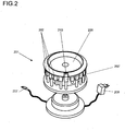
- a holding rack of a laboratory setup is configured as a carousel where the dosage units are arranged around the circumference.
- the stepwise rotation of the carousel is programmed so that the dosage unit for the current step is turned towards the user.
- the unit to be used in the current step is indicated to the user through its position on the carousel.
- this carousel rack could be equipped with the aforementioned locking feature whereby all dosage units are locked into their seating positions in the carousel, and only the dosage unit in the position for the current step of the dosage-dispensing process is unlocked.
- the locking feature could be realized with a stationary cover over the carousel preventing access to all dosage units on the carousel except for an access window or cutout in the stationary cover giving access to the one dosage unit which has been moved to the cutout window by the carousel for the current dispensing step.
- the dosage units are arranged in the rack in the order in which they are used in the dispensing process, for example from left to right in a linear rack or clockwise in a carousel rack.
- the dosage units have to be set into the rack in the prescribed order before the dispensing process is started.
- the holding rack of the laboratory setup further comprises for each indicator light a push button and an indicator device for representing specific data related to the dosage unit and/or related to the specific data of the substance inside said dosage unit, for which the related push button has been operated.
- Said indicator device could be a screen or a touch screen.
- the representation of the data can be performed in many ways, even the data of all dosage units could be represented, in example in a scroll up menu.
- Typical specific data related to the dosage unit could be the number of already performed dispensings as well as the remaining quantity of powder.
- Typical specific data related to the substance could be the chemical formula, the date of production and the lifetime of the substance as well as the dangerous substance class.
- the dispensing head of each dosage unit carries an ID tag, for example a barcode or matrix-code label or in particular an RFID (Radio Frequency Identification) tag or label, also known as transponder tag.
- ID tag for example a barcode or matrix-code label or in particular an RFID (Radio Frequency Identification) tag or label, also known as transponder tag.
- the holding rack is advantageously equipped with a reader device, so that the dosage unit in each rack position can be identified by a processor unit that is incorporated in the rack or connected to the holding rack as an external processor unit, for example a computer or the processor unit of a dispensing setup. As a minimum, this I.D.
- tag identifies the substance in the dosage unit, but it can also include additional information such as the total amount of substance stored in the dosage unit and the date when the dosage unit was last filled, as well as an expiration date for the substance currently contained in the dosage unit.
- the last-mentioned concept of using I.D. tags on dosage units as part of an inventory management system provides not only a systematic control over inventory processes such as reordering of supplies, discarding substances that are past their expiration dates, refilling of dosage units, etc., it can also serve for the control of substances that are regulated under the law (highly toxic substances, prescription drugs, etc.).
- the control could be exercised for example by requiring a user to be registered electronically on the system before the aforementioned locking feature will unlock any dosage units from their seats in the rack, and by keeping track of the date and time when a dosage unit was taken from the rack and returned to the rack.
- the aforementioned processor or I.D. tag attached on the holding rack, the dosing head or on a receiving container includes a memory unit in which a procedure is stored which gives the substance quantities and the order of sequence in which they are to be dispensed from their respective dosage units.
- the processor is able to activate the indicating lights and/or release the locks and/or set the carousel positions according to the prescribed sequence of dosage units. Consequently, it is unnecessary for the dosage units to be set in the rack in any particular order.
- This concept is considered particularly advantageous for mixing procedures that involve hazardous substances where the entire batching procedure should be handled with a completely enclosed setup inside a glove box.
- the dosage units have to be placed into the glove box inside their safety containers.
- the foregoing concept of treating the containers themselves as "single-unit racks" eliminates the steps of transferring the dosage units from their individual safety containers into a rack and later returning them to the safety containers, which are much more cumbersome to perform inside a glove box.
- a plurality of containers each holding one dosage unit, can be placed on and connected to a base plate or shelf plate (not shown in the drawings), for example with mechanical and electrical plug connections which on the one hand secure each container to its assigned place on the base plate and on the other hand provide the electrical connections for the indicator lights as well as for the release of the locking devices that hold the dosage units locked in the containers.
- a base plate or shelf plate not shown in the drawings
- Having the containers secured on a shelf plate or other kind of holding base has the advantage that a dosage unit can be pulled out of its safety container with one hand while the container stays in its place on the support base. This simplifies the manipulation in particular inside a glove box.
- the means of indication could be incorporated in the dispensing head of the dosage unit instead of on the rack or individual container.
- the indicator e.g. an indicator light on the dispensing head
- the indicator could be energized through electrical contacts in the rack, or by means of a small battery in the dispensing head, or the small amount of energy required for the indicator light (for example a light-emitting diode) could also be received inductively by the dispensing head through a coil or antenna.
- the linear holding rack 101 is filled with dosage units 102, where each dosage unit 102 consists of a supply receptacle 104 in the form of a vial with a dispensing head 103 connected to it.
- the dispensing head 103 alone without a vial can be used as dosage unit 102' for very small substance quantities.
- the opening in the dispensing head 103' where otherwise the neck of a vial would be connected serves in this case as supply receptacle 104'. After the dosage unit 102' has been filled with substance, the opening is closed off with a plug or cap 106.
- the dosage units 102, 102' can be taken out of the holding rack 101 by swiveling the bottom of a dosage unit forward from the rack, and the reverse sequence of movements is used to return a dosage unit to the rack.
- An indicator light 105, 105' is arranged above each seating position in the holding rack.
- the dosage unit 102, 102' to be taken out of the holding rack 101 for the next dispensing step is indicated by the light 105' in the respective position being lit up while the other lights 105 remain dark, or the light 105' that belongs to the dosage unit for the current dispensing step lights up in a first colour, e.g. green, while the lights 105 at the other dosage units light up in a second colour, e.g. red.
- the holding rack 101 further comprises for each indicator light 105, 105' a push button 107 and an indicator device 108 for representing specific data related to the dosage unit 102 and/or related to the specific data of the substance inside said dosage unit 102 for which the related push button 107 has been manually operated.
- Said indicator device 108 could be a screen or a touch screen. The representation of the data can be performed in many ways, even the data of all dosage units 102, 102' could be represented, in example in a scroll up menu.
- Figure 2 shows a holding rack 201 where the positions for the dosage units 202 are arranged on a carousel.
- the carousel which has a drive mechanism energized by a power supply 208, rotates to a position facing the user where the particular dosage unit 202' to be taken out next in the batching process step presents itself to the user.
- the concept of a carousel rack 201 also offers the possibility to lock all dosage units 202 into their seating positions in the rack except said particular dosage unit 202'.
- the dosage units 102, 102', 202 can be arranged in the rack in the order in which they are used in the dispensing process, requiring the operator to set the dosage units into the rack in the prescribed order before the dispensing process is started, for example from left to right in the case of the holding rack 101 or clockwise in the case of the holding rack 201.
- the holding rack then turns on the indicator lights or changes the carousel positions in the corresponding sequential order.
- the holding rack 201 includes a reader device for electronically readable I.D. labels, for example RFID tags, transponder tags, barcodes, etc., which are affixed to the dosage units 202.
- the holding rack 201 has a bidirectional first interface connection 207 to a processor unit (see Fig.
- the dosage units 202 carry transponder tags, whereby the processor unit is enabled to identify each dosage unit 202 and to send control commands to the holding rack 201 to move the dosage units 202 to the "take-out" position at the cutout 210 in any order prescribed by a program in the processor, so that the dosage units 202 do not need to be in sequential clockwise or counterclockwise order in the carousel rack 201.
- an electronic reader device connected to a processor can be used analogously with the holding rack 101 of Figure 1a , where the processor would send the respective command signals to the indicator lights.
- Figures 3a and 3b illustrate the singular case of a holding rack 301 in the form of a container that holds only one dosage unit 302.
- the supply receptacle 304 is funnel- or hopper-shaped, open on top to fill in the substance and then closed with a cap.
- a plurality of holding containers 301 are used to hold the dosage units 302.
- Each container 301 has an indicator light 305 and an electronically readable I.D. label 306, and all of the containers used in the process are interfaced to a common processor unit preferably through a wireless connection. The information on the I.D.
- the processing unit controls the indicator lights 305 on the holding containers 301.
- the indicator light 305 as well as the I.D. label 306 could also be arranged on the dosage unit 302 instead of on the container 301. In either case, the small amount of power required for the indicator light could be supplied by a battery or transmitted inductively through an RF antenna incorporated in the container 301 or the dosage unit 302.
- a safety container functioning as a single-unit rack is particularly advantageous for mixing procedures that involve hazardous substances where the entire batching procedure has to be handled with a completely enclosed setup inside a glove box. If traces of the hazardous substance remain clinging to the outside of the dispensing head after a step in the batching procedure has been completed, the risk that the substance could escape into the environment is prevented by the holding container or safety container 301.
- a multi-unit rack 101, 201 according to Figure 1 or Figure 2 inside a glove box and to transfer the dosage units from their safety containers to the multi-unit rack 101, 201 in the glove box. However, this takes up more space inside the glove box and adds the steps of transferring the dosage units between their safety containers and the holding rack 101, 201.
- a plurality of containers 301 can be placed on and connected to a base plate or shelf plate.
- Figure 3c shows a base plate or shelf plate 310 with three seating positions A, B, C for containers 301.
- the feet 308 of a container 301 plug or snap into matching openings 311 on the base plate 310, and electrical contact elements 307 on the container 301 meet electrical contact elements 312 on the base plate 310.
- the electrical contacts 307, 312 provide the electrical connections to the indicator lights 305 as well as to the locking devices 309.
- the locking device 309 keeps the dosage unit 302 locked into the safety container 301, and releases the lock only when it is energized through the electrical contacts 307, 312 under the control of a processor unit.
- a dosage unit 302 can be pulled out of its respective safety container 301 with one hand while the container 301 stays in its place on the tray, which simplifies the manipulation in particular inside a glove box.
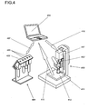
- Figure 4 schematically illustrates a typical laboratory setup with a holding rack 401 (without push buttons and display) for dosage units, a laboratory balance 413 with a dosage-dispensing device 417, a computer or processor unit 414, and the respective communication paths 407 between computer and holding rack, 415 between computer and balance, and 416 between computer and dosage-dispensing device.
- a dosage unit 402' whose indicator light 405' is lit up has been taken out of the holding rack 401 and coupled to the dosage-dispensing device 417 to dispense substance into a receiving container 411 resting on a weighing pan 412.
- the computer receives the substance data from the RFID tags on the dosage units and controls the indicator lights based 405 on a procedure stored in the computer.
- the balance sends weight data to the computer through the signal connection 415.
- the computer through the interface connection 416, controls the speed and the shut-off point of the dosage-dispensing device 417 in accordance with a weight target given in the aforementioned procedure.
- hosts Lake Sear 101,401 linear rack 102, 102', 202, 302, 402, 402' dosage unit 103, 103', 203, 303 dispensing head 104, 104', 204, 304 supply receptacle, vial 105,405 indicator light, dark 105', 405' indicator light, activated 106 plug or cap 107 push button 108 indicator device 201 carousel rack 207,407 bidirectional signal connection 208 power supply 209 stationary bell cover of carousel 210 cutout in bell cover 209 301 safety container, single-unit rack 305 indicator light 306 ID label such as a transponder tag, barcode, etc.
Landscapes
- Business, Economics & Management (AREA)
- Chemical & Material Sciences (AREA)
- Engineering & Computer Science (AREA)
- Economics (AREA)
- Human Resources & Organizations (AREA)
- Quality & Reliability (AREA)
- Accounting & Taxation (AREA)
- Finance (AREA)
- Development Economics (AREA)
- Clinical Laboratory Science (AREA)
- Health & Medical Sciences (AREA)
- Entrepreneurship & Innovation (AREA)
- Analytical Chemistry (AREA)
- Marketing (AREA)
- Operations Research (AREA)
- Chemical Kinetics & Catalysis (AREA)
- Strategic Management (AREA)
- Tourism & Hospitality (AREA)
- Physics & Mathematics (AREA)
- General Business, Economics & Management (AREA)
- General Physics & Mathematics (AREA)
- Theoretical Computer Science (AREA)
- Automatic Analysis And Handling Materials Therefor (AREA)
- Warehouses Or Storage Devices (AREA)
- Medical Preparation Storing Or Oral Administration Devices (AREA)
Claims (16)
- Laboraufbau, der eine Laborwaage (413) mit einer Dosierungsabgabe-Einrichtung (417), eine Prozessoreinheit (414) und ein Haltegestell (101, 201, 301, 401) mit Dosierungseinheiten (102, 102', 202, 302, 402, 402') zum Abgeben von pulverförmigen Substanzen, falls das letztere an die Dosierungsabgabe-Einrichtung (417) gekoppelt ist, umfasst, wobei eine Dosierungseinheit (102, 102', 202, 302) einen Vorratsbehälter (104, 104', 204, 304) und einen Abgabekopf (103, 103', 203, 303), die miteinander verbunden sind, umfasst, wobei ein Wiegesignal (415) von der Waage (413) an die Prozessoreinheit (414), welche die Dosierungsabgabe-Einrichtung (417) steuert, zurückgemeldet wird und wobei jede Dosierungseinheit (102, 102', 202, 302, 402, 402') eine individuelle Position oder Abteilung des Haltegestells (101, 201, 301, 401) einnimmt, dadurch gekennzeichnet, dass der Laboraufbau mit einem jeweiligen Übertragungsweg oder einer Schnittstellenverbindung (407) zwischen der Prozessoreinheit (414) und dem Haltegestell (101, 201, 301, 401) ausgestattet ist und das Haltegestell (101, 201, 301, 401) mit einem aktiven Benutzerführungsmittel (105, 105', 210, 305, 405, 405') ausgestattet ist, das bei einem Vorgang des Abgebens von abgemessenen Substanzmengen aus unterschiedlichen Dosierungseinheiten in einen Aufnahmebehälter (411) durch die Prozessoreinheit (414) gesteuert wird, auf der Grundlage eines Verfahrens, das in einer Speichereinheit der Prozessoreinheit (414) gespeichert ist, um den Benutzer beim Herausnehmen und Zurückstellen der unterschiedlichen Dosierungseinheiten (102, 102', 202, 302, 402, 402'), die in dem Haltegestell (101, 201, 301, 401) sitzen, zu leiten.
- Laboraufbau nach Anspruch 1, dadurch gekennzeichnet, dass das aktive Benutzerführungsmittel (105, 105', 210, 305, 405, 405') ein an dem Haltegestell (101, 201, 301, 401) angeordnetes Anzeigemittel (105, 105', 210, 305, 405, 405') umfasst, das einem Bediener sichtbar anzeigt, welche Dosierungseinheit (102, 102', 202, 302, 402, 402') bei einem aktuellen Schritt eines Dosierungsabgabeverfahren aufgerufen wird.
- Laboraufbau nach Anspruch 1 oder 2, dadurch gekennzeichnet, dass das aktive Benutzerführungsmittel (105, 105', 210, 305, 405, 405') eine physische oder drahtlose Signalverbindung von dem Haltegestell (101, 201, 301, 401) zu einem an jeder Dosierungseinheit (102, 102', 202, 302, 402, 402') angeordneten Anzeigemittel (105, 105', 210, 305, 405, 405') umfasst, das einem Bediener sichtbar anzeigt, welche Dosierungseinheit (102, 102', 202, 302, 402, 402') bei einem aktuellen Schritt eines Dosierungsabgabeverfahren aufgerufen wird.
- Laboraufbau nach Anspruch 1 oder 2, dadurch gekennzeichnet, dass die Positionen für die Dosierungseinheiten in einer geraden Reihe angeordnet sind, und wobei das Anzeigemittel (105, 105', 210, 305, 405, 405') Anzeigelichter (105) umfasst, die an dem Haltegestell (101) über jeder der jeweiligen Haltepositionen für die Dosierungseinheiten (102) angeordnet sind, und wobei das Licht (105'), das zu der Dosierungseinheit (102') für den aktuellen Schritt des Verfahrens gehört, erleuchtet wird, während die anderen Lichter (105) dunkel bleiben, oder das Licht (105'), das zu der Dosierungseinheit für den aktuellen Schritt des Verfahrens gehört, eine erste Farbe hat, während die Lichter (105) an den anderen Dosierungseinheiten eine zweite Farbe haben.
- Laboraufbau nach einem der Ansprüche 1 bis 3, dadurch gekennzeichnet, dass die Positionen für die Dosierungseinheiten (102, 102', 202, 302, 402, 402') auf einem Karussell (201) angeordnet sind, wobei das aktive Benutzerführungsmittel (105, 105', 210, 305, 405, 405') eine Fähigkeit des Karussells (201) umfasst, sich zu einer Position (210) zu drehen, wo sich die Dosierungseinheit (102, 102', 202, 302, 402, 402') für den aktuellen Schritt dem Benutzer darbietet.
- Laboraufbau nach einem der Ansprüche 1 bis 5, die ferner ein Mittel (209, 309) umfasst, um alle Dosierungseinheiten (102, 102', 202, 302, 402, 402') in ihrer Befestigungsposition in dem Haltegestell (101, 201, 301, 401) zu verriegeln, und nur die Dosierungseinheit (102, 102', 202, 302, 402, 402') in der Position (210) für den aktuellen Abgabeschritt entriegelt ist, so dass sie durch den Benutzer herausgenommen werden kann.
- Laboraufbau nach einem der vorhergehenden Ansprüche, dadurch gekennzeichnet, dass die Dosierungseinheiten (102, 102', 202, 302, 402, 402') in dem Haltegestell (101, 201, 301, 401) in der Reihenfolge angeordnet sind, in der sie bei einem Abgabeverfahren verwendet werden, was erfordert, dass der Bediener die Dosierungseinheiten (102, 102', 202, 302, 402, 402')in der vorgeschriebenen Reihenfolge in das Haltegestell (101, 201, 301, 401) einsetzt, bevor da Abgabeverfahren begonnen wird.
- Laboraufbau nach einem der Ansprüche 1 bis 7, dadurch gekennzeichnet, dass das Haltegestell (101, 201, 301, 401) ferner eine Leseeinrichtung für Identifikationsetiketten, insbesondere Transpondermarken, HF-Identifikationsmarken, Strichcode-Etiketten oder Matrixetiketten, umfasst und dass die Dosierungseinheiten (102, 102', 202, 302, 402, 402') Identifikationsetiketten (306), insbesondere Transpondermarken, HF-Identifikationsmarken, Strichcode-Etiketten oder Matrixetiketten, tragen, wodurch die Prozessoreinheit (414) dazu in die Lage versetzt wird, jede Dosierungseinheit (102, 102', 202, 302, 402, 402') und ihre Position in dem Haltegestell (101, 201, 301, 401) zu identifizieren.
- Laboraufbau nach einem der Ansprüche 1 bis 8, dadurch gekennzeichnet, dass die Prozessoreinheit (414) eine Speichereinheit umfasst, in der ein Verfahren, mit Daten bezüglich der Substanzen und der Reihenfolge, in der sie aus ihren jeweiligen Dosierungseinheiten (102, 102', 202, 302, 402, 402') abzugeben sind, gespeichert ist, so dass auf der Grundlage des Verfahrens sowie der Identifikationsetikettendaten und der Haltegestellposition jeder Dosierungseinheit (102, 102', 202, 302, 402, 402') die Prozessoreinheit (414) dazu in der Lage ist, die Anzeigelichter (105) zu aktivieren und/oder eine Dosierungseinheit (102, 102', 202, 302, 402, 402') zu einer Herausnahmeposition für einen aktuellen Schritt eines Abgabeverfahrens zu bringen und/oder die Dosierungseinheit (202), die bei dem aktuellen Schritt eines Abgabeverfahrens aus dem Gestell herauszunehmen ist, zu entriegeln.
- Laboraufbau nach einem der Ansprüche 1 bis 9, dadurch gekennzeichnet, dass der Laboraufbau ferner eine Waage und eine Dosierungsabgabe-Einrichtung (417) umfasst und dass die Prozessoreinheit (414) ferner eine zweite Schnittstellenverbindung (415) zu der Waage (413) und eine dritte Schnittstellenverbindung (416) zu der Dosierungsabgabe-Einrichtung (417) hat, wobei eine Dosierungseinheit (102, 102', 202, 302, 402, 402') an die Dosierungsabgabe-Einrichtung (417) gekoppelt werden kann und ein Aufnahmebehälter (411) unter der Dosierungseinheit (102, 102', 202, 302, 402, 402') auf einer Waagschale (412) der Waage (413) aufgebaut werden kann, wobei die Waage (413) durch die zweite Schnittstellenverbindung (415) Wiegesignale an die Prozessoreinheit (414) sendet und die Prozessoreinheit (414) Dosierungseinheit (102, 102', 202, 302, 402, 402') durch die dritte Schnittstellenverbindung (416) die Geschwindigkeit und das Abstellen der Substanzabgabe aus der Dosierungseinheit (102, 102', 202, 302, 402, 402') in den Aufnahmebehälter (411) steuert.
- Laboraufbau nach einem der vorhergehenden Ansprüche, dadurch gekennzeichnet, dass mehrere Haltegestelle (101, 201, 301, 401) mit der Fähigkeit versehen sind, in einer Gruppe kombiniert zu werden, die zusammen als ein Haltegestell (101, 201, 301, 401) unter der Steuerung der Prozessoreinheit (414) zusammenarbeitet, die in einem der Haltegestelle (101, 201, 301, 401) der Gruppe integriert ist oder extern mit der Gruppe verbunden ist.
- Laboraufbau nach Anspruch 11, dadurch gekennzeichnet, dass wenigstens eines der Haltegestelle (101, 201, 301, 401), die als eine Gruppe zusammenwirken, ein Einzeleinheitengestell (301) mit nur einer Position oder Abteilung für eine Dosierungseinheit (302) ist.
- Laboraufbau nach Anspruch 12, dadurch gekennzeichnet, dass mehrere Einzeleinheitengestelle (301) auf einer Grundplatte oder Gestellplatte (310) festsitzen und mit derselben verbunden sind, wobei eine mechanische Verbindung (308, 311) das Einzeleinheitengestell (301) in einer zugewiesenen Position (A, B, C) befestigt und eine elektrische Verbindung (307, 312) wenigstens eine der Komponenten Anzeigelicht (305) und Verriegelung (309) an dem Einzeleinheitengestell (301) mit Strom versorgt.
- Laboraufbau nach Anspruch 4, dadurch gekennzeichnet, dass das Haltegestell (101, 201, 301, 401) ferner für jedes Anzeigelicht (105, 105') einen Druckknopf (107) und eine Anzeigeeinrichtung (108) zum Darstellen spezifischer Daten, die mit der Dosierungseinheit (102, 102', 202, 302, 402, 402') verbunden sind und/oder mit der Substanz innerhalb der Dosierungseinheit (102, 102', 202, 302, 402, 402') verbunden sind, für die der verknüpfte Druckknopf (107) betätigt wird, umfasst.
- Laboraufbau nach Anspruch 8, dadurch gekennzeichnet, dass die Identifikationsetiketten (306), die Leseeinrichtung und die Prozessoreinheit (414) in einem Bestandsmanagementsystem für die Dosierungseinheiten (102, 102', 202, 302, 402, 402') und die in ihnen enthaltenen Substanzen integriert sind.
- Laboraufbau nach Anspruch 10 und 15, dadurch gekennzeichnet, dass die Identifikationsetiketten (306), die Leseeinrichtung, die Prozessoreinheit (414) sowie die Verriegelungsmittel (209, 309) in ein Zugriffskontroll- und Überwachungssystem integriert sind, um eine unerlaubte Verwendung der Dosierungseinheiten (102, 102', 202, 302, 402, 402') und der in ihnen enthaltenen Substanzen zu verhindern.
Priority Applications (5)
| Application Number | Priority Date | Filing Date | Title |
|---|---|---|---|
| EP07106744A EP1985367B1 (de) | 2007-04-23 | 2007-04-23 | Haltegestell für Dosierungseinheiten mit aktiver Benutzeranleitungsvorrichtung |
| AT07106744T ATE525134T1 (de) | 2007-04-23 | 2007-04-23 | Haltegestell für dosierungseinheiten mit aktiver benutzeranleitungsvorrichtung |
| US12/101,246 US7825821B2 (en) | 2007-04-23 | 2008-04-11 | Holding rack for dosage units with an active user-guiding means |
| CN2008100917528A CN101293216B (zh) | 2007-04-23 | 2008-04-14 | 具有有源用户引导装置的配料单元保持架 |
| JP2008105715A JP5247218B2 (ja) | 2007-04-23 | 2008-04-15 | 能動的なユーザーガイド手段を備えた投与ユニット用の保持ラック |
Applications Claiming Priority (1)
| Application Number | Priority Date | Filing Date | Title |
|---|---|---|---|
| EP07106744A EP1985367B1 (de) | 2007-04-23 | 2007-04-23 | Haltegestell für Dosierungseinheiten mit aktiver Benutzeranleitungsvorrichtung |
Publications (2)
| Publication Number | Publication Date |
|---|---|
| EP1985367A1 EP1985367A1 (de) | 2008-10-29 |
| EP1985367B1 true EP1985367B1 (de) | 2011-09-21 |
Family
ID=38481393
Family Applications (1)
| Application Number | Title | Priority Date | Filing Date |
|---|---|---|---|
| EP07106744A Not-in-force EP1985367B1 (de) | 2007-04-23 | 2007-04-23 | Haltegestell für Dosierungseinheiten mit aktiver Benutzeranleitungsvorrichtung |
Country Status (5)
| Country | Link |
|---|---|
| US (1) | US7825821B2 (de) |
| EP (1) | EP1985367B1 (de) |
| JP (1) | JP5247218B2 (de) |
| CN (1) | CN101293216B (de) |
| AT (1) | ATE525134T1 (de) |
Families Citing this family (8)
| Publication number | Priority date | Publication date | Assignee | Title |
|---|---|---|---|---|
| GB0411577D0 (en) | 2004-05-24 | 2004-06-23 | Ivf Ltd | Identification of biological samples |
| JP2008298495A (ja) * | 2007-05-30 | 2008-12-11 | Hitachi High-Technologies Corp | 検体ラック、及び検体搬送システム |
| USD623734S1 (en) * | 2007-07-19 | 2010-09-14 | Otsuka Pharmaceutical Factory, Inc. | Portion of an infusion solution bag |
| KR101413742B1 (ko) * | 2013-04-10 | 2014-08-06 | 한국생산기술연구원 | 분말조제 계량을 위한 용량 조절 장치 및 방법 |
| KR101396787B1 (ko) | 2014-02-28 | 2014-05-20 | 주식회사 나노하이테크 | 원료 계량장치 |
| JP7019303B2 (ja) * | 2017-03-24 | 2022-02-15 | 東芝テック株式会社 | 液滴分注装置 |
| CN106984371B (zh) * | 2017-06-13 | 2022-04-22 | 中国农业科学院郑州果树研究所 | 一种适合于污染区使用的pe手套支架 |
| JP2025517674A (ja) * | 2023-04-03 | 2025-06-10 | エルジー・ケム・リミテッド | 試料内金属成分検査のための前処理システムおよび前処理方法 |
Family Cites Families (21)
| Publication number | Priority date | Publication date | Assignee | Title |
|---|---|---|---|---|
| JP2705246B2 (ja) * | 1989-09-28 | 1998-01-28 | 株式会社島津製作所 | 粉体サンプリング用カートリッジ及び粉体サンプリング装置 |
| CA2299118C (en) * | 1990-03-02 | 2006-08-08 | Ventana Medical Systems, Inc. | Automated biological reaction apparatus |
| US5595707A (en) * | 1990-03-02 | 1997-01-21 | Ventana Medical Systems, Inc. | Automated biological reaction apparatus |
| US5143210A (en) * | 1991-01-31 | 1992-09-01 | Warwick S John | Foldable protective package for storing, dispensing, and displaying diagnostic kit components |
| JPH052023A (ja) * | 1991-06-25 | 1993-01-08 | Fuaruko Bio Syst:Kk | 検査血液分注指示装置 |
| US5525304A (en) * | 1994-06-24 | 1996-06-11 | Pasteur Sanofi Diagnostics | Apparatus for automated chemical analysis with variable reagents |
| US5752621A (en) * | 1995-03-20 | 1998-05-19 | Eigen Technology Inc. | Smart automatic medication dispenser |
| US5609822A (en) * | 1995-07-07 | 1997-03-11 | Ciba Corning Diagnostics Corp. | Reagent handling system and reagent pack for use therein |
| US6066300A (en) * | 1995-07-07 | 2000-05-23 | Bayer Corporation | Reagent handling system and configurable vial carrier for use therein |
| JPH09128463A (ja) * | 1995-10-31 | 1997-05-16 | Fujitsu Ltd | 属性表示システム |
| JPH09196925A (ja) * | 1996-01-19 | 1997-07-31 | Hitachi Ltd | 自動分析装置 |
| US5971594A (en) * | 1998-03-24 | 1999-10-26 | Innovative Medical Devices, Inc. | Medication dispensing system |
| US6387330B1 (en) * | 2000-04-12 | 2002-05-14 | George Steven Bova | Method and apparatus for storing and dispensing reagents |
| US6674022B2 (en) * | 2001-03-23 | 2004-01-06 | Ortho-Mcneil Pharmaceutical, Inc. | Apparatus and method for transferring and weighing powder materials using pipette transfer devices |
| US20030183642A1 (en) * | 2002-03-26 | 2003-10-02 | Kempker Jeffrey A. | Pill dispensing apparatus |
| FR2846632B1 (fr) * | 2002-10-31 | 2006-02-10 | Mettler Toledo Flexilab Sas | Appareil pour le dosage de precision de poudre |
| EP1452849B1 (de) * | 2003-02-27 | 2016-02-24 | Mettler-Toledo GmbH | Vorrichtung und Verfahren zur Herstellung von Lösungen und/oder Verdünnungen im Labor |
| JP4843258B2 (ja) * | 2004-06-18 | 2011-12-21 | 株式会社東芝 | 分析装置 |
| WO2006009251A1 (ja) * | 2004-07-22 | 2006-01-26 | Wako Pure Chemical Industries, Ltd. | 分析支援方法、分析装置、遠隔コンピュータ、データ解析方法及びプログラム並びに試薬容器 |
| ATE396919T1 (de) * | 2004-12-23 | 2008-06-15 | Mettler Toledo Flexilab Sas | Vorrichtung und verfahren zum dosieren von substanzen in behältern |
| US7614429B2 (en) * | 2005-05-18 | 2009-11-10 | Symyx Solutions, Inc. | Apparatus and methods for storing and dispensing solid material |
-
2007
- 2007-04-23 EP EP07106744A patent/EP1985367B1/de not_active Not-in-force
- 2007-04-23 AT AT07106744T patent/ATE525134T1/de not_active IP Right Cessation
-
2008
- 2008-04-11 US US12/101,246 patent/US7825821B2/en active Active
- 2008-04-14 CN CN2008100917528A patent/CN101293216B/zh not_active Expired - Fee Related
- 2008-04-15 JP JP2008105715A patent/JP5247218B2/ja not_active Expired - Fee Related
Also Published As
| Publication number | Publication date |
|---|---|
| US20080262651A1 (en) | 2008-10-23 |
| CN101293216A (zh) | 2008-10-29 |
| CN101293216B (zh) | 2012-05-30 |
| US7825821B2 (en) | 2010-11-02 |
| JP2008292468A (ja) | 2008-12-04 |
| EP1985367A1 (de) | 2008-10-29 |
| JP5247218B2 (ja) | 2013-07-24 |
| ATE525134T1 (de) | 2011-10-15 |
Similar Documents
| Publication | Publication Date | Title |
|---|---|---|
| EP1985367B1 (de) | Haltegestell für Dosierungseinheiten mit aktiver Benutzeranleitungsvorrichtung | |
| EP3240626B1 (de) | Mischen von flüssigkeiten | |
| US6988634B2 (en) | Cartridge for dispensing pill - or capsule-form medications in desired doses | |
| US8380346B2 (en) | System and apparatus for item management | |
| CA2451069C (en) | High capacity drawer with mechanical indicator for a dispensing device | |
| US9977872B2 (en) | Dispensing system for pharmacies | |
| DK178312B1 (en) | Apparatus and method for controlled dosing and filling of pills, in multi-compartment trays, intended for medicine dispensers or pill boxes | |
| US12042470B2 (en) | Drug dispensing device | |
| JP7198525B2 (ja) | 秤量装置 | |
| US8201592B2 (en) | Method and arrangement for making up preparations | |
| WO2012163710A1 (en) | Medication dispensing apparatus | |
| JP2022179598A (ja) | 秤量装置 | |
| JP7045682B2 (ja) | 秤量装置 | |
| JP6979194B2 (ja) | 秤量装置 | |
| WO2020162413A1 (ja) | 散薬秤量システム | |
| JP2025161909A (ja) | 薬剤包装装置 | |
| JP2020037015A (ja) | 秤量装置 | |
| HK1107759A (en) | An intelligent dispensing device for dispensing pill-or capsule-form medications in desired doses |
Legal Events
| Date | Code | Title | Description |
|---|---|---|---|
| PUAI | Public reference made under article 153(3) epc to a published international application that has entered the european phase |
Free format text: ORIGINAL CODE: 0009012 |
|
| AK | Designated contracting states |
Kind code of ref document: A1 Designated state(s): AT BE BG CH CY CZ DE DK EE ES FI FR GB GR HU IE IS IT LI LT LU LV MC MT NL PL PT RO SE SI SK TR |
|
| AX | Request for extension of the european patent |
Extension state: AL BA HR MK RS |
|
| 17P | Request for examination filed |
Effective date: 20081112 |
|
| 17Q | First examination report despatched |
Effective date: 20081215 |
|
| AKX | Designation fees paid |
Designated state(s): AT BE BG CH CY CZ DE DK EE ES FI FR GB GR HU IE IS IT LI LT LU LV MC MT NL PL PT RO SE SI SK TR |
|
| GRAP | Despatch of communication of intention to grant a patent |
Free format text: ORIGINAL CODE: EPIDOSNIGR1 |
|
| GRAS | Grant fee paid |
Free format text: ORIGINAL CODE: EPIDOSNIGR3 |
|
| GRAA | (expected) grant |
Free format text: ORIGINAL CODE: 0009210 |
|
| AK | Designated contracting states |
Kind code of ref document: B1 Designated state(s): AT BE BG CH CY CZ DE DK EE ES FI FR GB GR HU IE IS IT LI LT LU LV MC MT NL PL PT RO SE SI SK TR |
|
| REG | Reference to a national code |
Ref country code: GB Ref legal event code: FG4D |
|
| REG | Reference to a national code |
Ref country code: CH Ref legal event code: EP |
|
| REG | Reference to a national code |
Ref country code: IE Ref legal event code: FG4D |
|
| REG | Reference to a national code |
Ref country code: DE Ref legal event code: R096 Ref document number: 602007017316 Country of ref document: DE Effective date: 20111201 |
|
| REG | Reference to a national code |
Ref country code: NL Ref legal event code: VDEP Effective date: 20110921 |
|
| PG25 | Lapsed in a contracting state [announced via postgrant information from national office to epo] |
Ref country code: FI Free format text: LAPSE BECAUSE OF FAILURE TO SUBMIT A TRANSLATION OF THE DESCRIPTION OR TO PAY THE FEE WITHIN THE PRESCRIBED TIME-LIMIT Effective date: 20110921 Ref country code: LT Free format text: LAPSE BECAUSE OF FAILURE TO SUBMIT A TRANSLATION OF THE DESCRIPTION OR TO PAY THE FEE WITHIN THE PRESCRIBED TIME-LIMIT Effective date: 20110921 Ref country code: SE Free format text: LAPSE BECAUSE OF FAILURE TO SUBMIT A TRANSLATION OF THE DESCRIPTION OR TO PAY THE FEE WITHIN THE PRESCRIBED TIME-LIMIT Effective date: 20110921 |
|
| LTIE | Lt: invalidation of european patent or patent extension |
Effective date: 20110921 |
|
| PG25 | Lapsed in a contracting state [announced via postgrant information from national office to epo] |
Ref country code: CY Free format text: LAPSE BECAUSE OF FAILURE TO SUBMIT A TRANSLATION OF THE DESCRIPTION OR TO PAY THE FEE WITHIN THE PRESCRIBED TIME-LIMIT Effective date: 20110921 Ref country code: LV Free format text: LAPSE BECAUSE OF FAILURE TO SUBMIT A TRANSLATION OF THE DESCRIPTION OR TO PAY THE FEE WITHIN THE PRESCRIBED TIME-LIMIT Effective date: 20110921 Ref country code: SI Free format text: LAPSE BECAUSE OF FAILURE TO SUBMIT A TRANSLATION OF THE DESCRIPTION OR TO PAY THE FEE WITHIN THE PRESCRIBED TIME-LIMIT Effective date: 20110921 Ref country code: GR Free format text: LAPSE BECAUSE OF FAILURE TO SUBMIT A TRANSLATION OF THE DESCRIPTION OR TO PAY THE FEE WITHIN THE PRESCRIBED TIME-LIMIT Effective date: 20111222 Ref country code: AT Free format text: LAPSE BECAUSE OF FAILURE TO SUBMIT A TRANSLATION OF THE DESCRIPTION OR TO PAY THE FEE WITHIN THE PRESCRIBED TIME-LIMIT Effective date: 20110921 |
|
| REG | Reference to a national code |
Ref country code: AT Ref legal event code: MK05 Ref document number: 525134 Country of ref document: AT Kind code of ref document: T Effective date: 20110921 |
|
| PG25 | Lapsed in a contracting state [announced via postgrant information from national office to epo] |
Ref country code: BE Free format text: LAPSE BECAUSE OF FAILURE TO SUBMIT A TRANSLATION OF THE DESCRIPTION OR TO PAY THE FEE WITHIN THE PRESCRIBED TIME-LIMIT Effective date: 20110921 |
|
| PG25 | Lapsed in a contracting state [announced via postgrant information from national office to epo] |
Ref country code: CZ Free format text: LAPSE BECAUSE OF FAILURE TO SUBMIT A TRANSLATION OF THE DESCRIPTION OR TO PAY THE FEE WITHIN THE PRESCRIBED TIME-LIMIT Effective date: 20110921 Ref country code: IS Free format text: LAPSE BECAUSE OF FAILURE TO SUBMIT A TRANSLATION OF THE DESCRIPTION OR TO PAY THE FEE WITHIN THE PRESCRIBED TIME-LIMIT Effective date: 20120121 Ref country code: SK Free format text: LAPSE BECAUSE OF FAILURE TO SUBMIT A TRANSLATION OF THE DESCRIPTION OR TO PAY THE FEE WITHIN THE PRESCRIBED TIME-LIMIT Effective date: 20110921 |
|
| PG25 | Lapsed in a contracting state [announced via postgrant information from national office to epo] |
Ref country code: EE Free format text: LAPSE BECAUSE OF FAILURE TO SUBMIT A TRANSLATION OF THE DESCRIPTION OR TO PAY THE FEE WITHIN THE PRESCRIBED TIME-LIMIT Effective date: 20110921 Ref country code: PT Free format text: LAPSE BECAUSE OF FAILURE TO SUBMIT A TRANSLATION OF THE DESCRIPTION OR TO PAY THE FEE WITHIN THE PRESCRIBED TIME-LIMIT Effective date: 20120123 Ref country code: PL Free format text: LAPSE BECAUSE OF FAILURE TO SUBMIT A TRANSLATION OF THE DESCRIPTION OR TO PAY THE FEE WITHIN THE PRESCRIBED TIME-LIMIT Effective date: 20110921 Ref country code: IT Free format text: LAPSE BECAUSE OF FAILURE TO SUBMIT A TRANSLATION OF THE DESCRIPTION OR TO PAY THE FEE WITHIN THE PRESCRIBED TIME-LIMIT Effective date: 20110921 Ref country code: RO Free format text: LAPSE BECAUSE OF FAILURE TO SUBMIT A TRANSLATION OF THE DESCRIPTION OR TO PAY THE FEE WITHIN THE PRESCRIBED TIME-LIMIT Effective date: 20110921 Ref country code: NL Free format text: LAPSE BECAUSE OF FAILURE TO SUBMIT A TRANSLATION OF THE DESCRIPTION OR TO PAY THE FEE WITHIN THE PRESCRIBED TIME-LIMIT Effective date: 20110921 |
|
| PLBE | No opposition filed within time limit |
Free format text: ORIGINAL CODE: 0009261 |
|
| STAA | Information on the status of an ep patent application or granted ep patent |
Free format text: STATUS: NO OPPOSITION FILED WITHIN TIME LIMIT |
|
| PG25 | Lapsed in a contracting state [announced via postgrant information from national office to epo] |
Ref country code: DK Free format text: LAPSE BECAUSE OF FAILURE TO SUBMIT A TRANSLATION OF THE DESCRIPTION OR TO PAY THE FEE WITHIN THE PRESCRIBED TIME-LIMIT Effective date: 20110921 |
|
| 26N | No opposition filed |
Effective date: 20120622 |
|
| REG | Reference to a national code |
Ref country code: DE Ref legal event code: R097 Ref document number: 602007017316 Country of ref document: DE Effective date: 20120622 |
|
| PG25 | Lapsed in a contracting state [announced via postgrant information from national office to epo] |
Ref country code: MC Free format text: LAPSE BECAUSE OF NON-PAYMENT OF DUE FEES Effective date: 20120430 |
|
| REG | Reference to a national code |
Ref country code: IE Ref legal event code: MM4A |
|
| PG25 | Lapsed in a contracting state [announced via postgrant information from national office to epo] |
Ref country code: IE Free format text: LAPSE BECAUSE OF NON-PAYMENT OF DUE FEES Effective date: 20120423 |
|
| PG25 | Lapsed in a contracting state [announced via postgrant information from national office to epo] |
Ref country code: ES Free format text: LAPSE BECAUSE OF FAILURE TO SUBMIT A TRANSLATION OF THE DESCRIPTION OR TO PAY THE FEE WITHIN THE PRESCRIBED TIME-LIMIT Effective date: 20120101 |
|
| PG25 | Lapsed in a contracting state [announced via postgrant information from national office to epo] |
Ref country code: BG Free format text: LAPSE BECAUSE OF FAILURE TO SUBMIT A TRANSLATION OF THE DESCRIPTION OR TO PAY THE FEE WITHIN THE PRESCRIBED TIME-LIMIT Effective date: 20111221 |
|
| PG25 | Lapsed in a contracting state [announced via postgrant information from national office to epo] |
Ref country code: MT Free format text: LAPSE BECAUSE OF FAILURE TO SUBMIT A TRANSLATION OF THE DESCRIPTION OR TO PAY THE FEE WITHIN THE PRESCRIBED TIME-LIMIT Effective date: 20110921 |
|
| REG | Reference to a national code |
Ref country code: CH Ref legal event code: PCOW Free format text: NEW ADDRESS: IM LANGACHER 44, 8606 GREIFENSEE (CH) |
|
| PG25 | Lapsed in a contracting state [announced via postgrant information from national office to epo] |
Ref country code: TR Free format text: LAPSE BECAUSE OF FAILURE TO SUBMIT A TRANSLATION OF THE DESCRIPTION OR TO PAY THE FEE WITHIN THE PRESCRIBED TIME-LIMIT Effective date: 20110921 |
|
| PG25 | Lapsed in a contracting state [announced via postgrant information from national office to epo] |
Ref country code: LU Free format text: LAPSE BECAUSE OF NON-PAYMENT OF DUE FEES Effective date: 20120423 |
|
| PG25 | Lapsed in a contracting state [announced via postgrant information from national office to epo] |
Ref country code: HU Free format text: LAPSE BECAUSE OF FAILURE TO SUBMIT A TRANSLATION OF THE DESCRIPTION OR TO PAY THE FEE WITHIN THE PRESCRIBED TIME-LIMIT Effective date: 20070423 |
|
| REG | Reference to a national code |
Ref country code: CH Ref legal event code: PFA Owner name: METTLER-TOLEDO GMBH, CH Free format text: FORMER OWNER: METTLER-TOLEDO AG, CH |
|
| REG | Reference to a national code |
Ref country code: FR Ref legal event code: PLFP Year of fee payment: 10 |
|
| REG | Reference to a national code |
Ref country code: FR Ref legal event code: PLFP Year of fee payment: 11 |
|
| REG | Reference to a national code |
Ref country code: DE Ref legal event code: R081 Ref document number: 602007017316 Country of ref document: DE Owner name: METTLER-TOLEDO GMBH, CH Free format text: FORMER OWNER: METTLER-TOLEDO AG, GREIFENSEE, CH |
|
| REG | Reference to a national code |
Ref country code: FR Ref legal event code: PLFP Year of fee payment: 12 |
|
| PGFP | Annual fee paid to national office [announced via postgrant information from national office to epo] |
Ref country code: GB Payment date: 20180328 Year of fee payment: 12 |
|
| REG | Reference to a national code |
Ref country code: FR Ref legal event code: CJ Effective date: 20180409 |
|
| PGFP | Annual fee paid to national office [announced via postgrant information from national office to epo] |
Ref country code: FR Payment date: 20180320 Year of fee payment: 12 |
|
| PGFP | Annual fee paid to national office [announced via postgrant information from national office to epo] |
Ref country code: CH Payment date: 20180425 Year of fee payment: 12 Ref country code: DE Payment date: 20180409 Year of fee payment: 12 |
|
| REG | Reference to a national code |
Ref country code: DE Ref legal event code: R119 Ref document number: 602007017316 Country of ref document: DE |
|
| REG | Reference to a national code |
Ref country code: CH Ref legal event code: PL |
|
| GBPC | Gb: european patent ceased through non-payment of renewal fee |
Effective date: 20190423 |
|
| PG25 | Lapsed in a contracting state [announced via postgrant information from national office to epo] |
Ref country code: DE Free format text: LAPSE BECAUSE OF NON-PAYMENT OF DUE FEES Effective date: 20191101 Ref country code: CH Free format text: LAPSE BECAUSE OF NON-PAYMENT OF DUE FEES Effective date: 20190430 Ref country code: GB Free format text: LAPSE BECAUSE OF NON-PAYMENT OF DUE FEES Effective date: 20190423 Ref country code: LI Free format text: LAPSE BECAUSE OF NON-PAYMENT OF DUE FEES Effective date: 20190430 |
|
| PG25 | Lapsed in a contracting state [announced via postgrant information from national office to epo] |
Ref country code: FR Free format text: LAPSE BECAUSE OF NON-PAYMENT OF DUE FEES Effective date: 20190430 |