EP1985233B1 - Verfahren und Vorrichtung zur Erfassung einer extrem unveränderlichen Drehachse - Google Patents
Verfahren und Vorrichtung zur Erfassung einer extrem unveränderlichen Drehachse Download PDFInfo
- Publication number
- EP1985233B1 EP1985233B1 EP08290390.7A EP08290390A EP1985233B1 EP 1985233 B1 EP1985233 B1 EP 1985233B1 EP 08290390 A EP08290390 A EP 08290390A EP 1985233 B1 EP1985233 B1 EP 1985233B1
- Authority
- EP
- European Patent Office
- Prior art keywords
- axis
- rotation
- sensor
- substantially invariant
- magnetic sensor
- Prior art date
- Legal status (The legal status is an assumption and is not a legal conclusion. Google has not performed a legal analysis and makes no representation as to the accuracy of the status listed.)
- Active
Links
Images


Classifications
-
- A—HUMAN NECESSITIES
- A61—MEDICAL OR VETERINARY SCIENCE; HYGIENE
- A61B—DIAGNOSIS; SURGERY; IDENTIFICATION
- A61B5/00—Measuring for diagnostic purposes; Identification of persons
- A61B5/103—Measuring devices for testing the shape, pattern, colour, size or movement of the body or parts thereof, for diagnostic purposes
- A61B5/11—Measuring movement of the entire body or parts thereof, e.g. head or hand tremor or mobility of a limb
- A61B5/1126—Measuring movement of the entire body or parts thereof, e.g. head or hand tremor or mobility of a limb using a particular sensing technique
-
- G—PHYSICS
- G01—MEASURING; TESTING
- G01C—MEASURING DISTANCES, LEVELS OR BEARINGS; SURVEYING; NAVIGATION; GYROSCOPIC INSTRUMENTS; PHOTOGRAMMETRY OR VIDEOGRAMMETRY
- G01C21/00—Navigation; Navigational instruments not provided for in groups G01C1/00 - G01C19/00
- G01C21/10—Navigation; Navigational instruments not provided for in groups G01C1/00 - G01C19/00 by using measurements of speed or acceleration
- G01C21/12—Navigation; Navigational instruments not provided for in groups G01C1/00 - G01C19/00 by using measurements of speed or acceleration executed aboard the object being navigated; Dead reckoning
- G01C21/16—Navigation; Navigational instruments not provided for in groups G01C1/00 - G01C19/00 by using measurements of speed or acceleration executed aboard the object being navigated; Dead reckoning by integrating acceleration or speed, i.e. inertial navigation
-
- G—PHYSICS
- G01—MEASURING; TESTING
- G01C—MEASURING DISTANCES, LEVELS OR BEARINGS; SURVEYING; NAVIGATION; GYROSCOPIC INSTRUMENTS; PHOTOGRAMMETRY OR VIDEOGRAMMETRY
- G01C25/00—Manufacturing, calibrating, cleaning, or repairing instruments or devices referred to in the other groups of this subclass
-
- A—HUMAN NECESSITIES
- A61—MEDICAL OR VETERINARY SCIENCE; HYGIENE
- A61B—DIAGNOSIS; SURGERY; IDENTIFICATION
- A61B2560/00—Constructional details of operational features of apparatus; Accessories for medical measuring apparatus
- A61B2560/02—Operational features
- A61B2560/0223—Operational features of calibration, e.g. protocols for calibrating sensors
-
- A—HUMAN NECESSITIES
- A61—MEDICAL OR VETERINARY SCIENCE; HYGIENE
- A61B—DIAGNOSIS; SURGERY; IDENTIFICATION
- A61B2562/00—Details of sensors; Constructional details of sensor housings or probes; Accessories for sensors
- A61B2562/02—Details of sensors specially adapted for in-vivo measurements
- A61B2562/0219—Inertial sensors, e.g. accelerometers, gyroscopes, tilt switches
-
- A—HUMAN NECESSITIES
- A61—MEDICAL OR VETERINARY SCIENCE; HYGIENE
- A61B—DIAGNOSIS; SURGERY; IDENTIFICATION
- A61B5/00—Measuring for diagnostic purposes; Identification of persons
- A61B5/68—Arrangements of detecting, measuring or recording means, e.g. sensors, in relation to patient
- A61B5/6801—Arrangements of detecting, measuring or recording means, e.g. sensors, in relation to patient specially adapted to be attached to or worn on the body surface
- A61B5/6813—Specially adapted to be attached to a specific body part
- A61B5/6824—Arm or wrist
Definitions
- the present invention relates to a method for detecting a substantially invariant axis of rotation of a movement of a solid.
- It also relates to a method for estimating a movement of a solid.
- the present invention relates to a device for detecting an axis of rotation substantially invariant of a movement of a solid.
- the present invention relates to the field of motion capture.
- the fields of application are varied and cover in particular the biomedical field, for the observation of the people, the sports domain, for the analysis of a movement, a sportsman himself or his equipment (rackets, balls ). It also applies to the field of automotive or robotics, as well as to virtual reality, and generally to any application comprising a moving body whose movement is to be determined or observed.
- Inertial systems consisting of one or more sensors chosen in particular from accelerometers, magnetometers or gyrometers having one or more axes of sensitivity are particularly known.
- inertial systems have the advantage of being autonomous and do not require prior equipment of the environment in which we observe the movement of a mobile.
- the principle consists of looking for quantities representative of the movement and orientation of the mobile, or its speed and speed of rotation or its acceleration and angular acceleration.
- the sensors are arranged on the observed mobile and it is sought to determine a movement potentially having six degrees of freedom, that is to say three degrees of freedom corresponding to the orientation of the solid in space and three degrees of freedom corresponding to the position of the mobile
- the object of the present invention is to solve the drawbacks of prior motion estimation systems and to propose a method that is particularly well suited to the processing of the movement of a mobile having a substantially invariant axis of rotation.
- the present invention aims at a method of detecting a substantially invariant axis of rotation of a movement of a mobile according to claim 1.
- the Applicant has found that by determining the substantially invariant axis of rotation among the measurements obtained at the output of the same sensor, it is possible to determine by the same axis substantially constant rotation of the movement of the equipped mobile of this sensor.
- the estimation of the axis of rotation in the space of the physical measurements requires to have at least three different measurements at different times and according to the three axes of sensitivity of the sensor, to allow the determination of the coordinates of the axis estimated rotation.
- an indicator of variations of the estimated axis of rotation it is possible to obtain an indication of the variations in the axis of rotation of the movement. If the value of this indicator is sufficiently low, ie of the order of the noise value of the physical measurements of the sensor observed, we can consider that the movement corresponds to a rotation about an axis substantially invariant. It is thus possible to validate the estimated axis of rotation in the space of the physical measurements as axis of rotation substantially invariant of the movement of the mobile.
- the rotation takes place around an axis of the physical field considered (the gravitational field for the accelerometers, the terrestrial magnetic field for the magnetometers), it is possible to determine the invariant axis of rotation using the other sensor, provided that the indicator of the variations in the axis of rotation estimated by means of the physical measurements of the sensor associated with the invariant physical field will necessarily be bad, that is to say much greater than the noise value of the measurements. obtained by this sensor.
- the estimation method may further comprise a step of determining the acceleration of the mobile.
- the motion estimation method of a mobile is facilitated since the number of unknowns to be determined is limited to the determination of the angle of rotation, and possibly the acceleration of the mobile.
- a method for calibrating an inertial or magnetic sensor with three sensitivity axes makes it possible to determine a rotation matrix adapted to transform the coordinates expressed in a sensor measurement mark into coordinates expressed in a predetermined coordinate system integral with a mobile carrying the sensor.
- This calibration method then makes it possible to express the measurements obtained at the sensor in a predetermined reference linked to the observed mobile, such as a housing enclosing the sensor or an anatomical part of an individual on which the sensor is positioned.
- the present invention relates, according to a fourth aspect, to a device for detecting a substantially invariant rotation axis of a movement of a mobile equipped with at least one inertial or magnetic sensor with three sensitivity axes.
- This detection device comprises means adapted to implement the detection method according to the invention.
- This detection device has characteristics and advantages similar to those described above in connection with the detection method.
- FIG. 1 a first embodiment of a method for detecting a substantially invariant axis of rotation of a movement of a moving body equipped with a sensor with three axes of sensitivity.
- This method can be applied to the study of the movement of a mobile in many applications since the movement of this mobile corresponds to a rotation about a fixed axis or substantially invariant.
- such a movement is observed for a vehicle in which roll and pitch are zero.
- the rotation of the vehicle corresponds to a rotation about a fixed vertical axis, corresponding to a yaw movement.
- the vertical acceleration is zero so that the movement of the vehicle is a planar motion.
- the movement of a wheel that rolls without sliding on a plane and in a straight line also corresponds to a movement about an axis of rotation, perpendicular to the plane of the wheel.
- Moving a computer mouse in a plane about an axis orthogonal to this plane is also a planar motion that can be observed in the context of the present invention.
- the method for detecting the substantially invariant axis of rotation of such a movement is implemented using a detection device equipped with at least one sensor with three axes of sensitivity, such as for example an accelerometer, a magnetometer or a gyrometer mounted tri-axis.
- the detection method consists of estimating a substantially invariant axis of rotation in the space of the physical measurements obtained by the sensor with three axes of sensitivity.
- the axis of rotation substantially invariant in the measurement space corresponds to the axis of weakest variation of the measurements for the magnetometer and the accelerometer and of greater variation for the gyrometer.
- Each measurement at an instant t obtained at the output of a sensor with three axes of sensitivity is considered as a point in the space of three-dimensional measurements.
- the invariant axis thus corresponds to the axis for which the measurements have for a magnetometer or an accelerometer the smallest variation on this axis, that is to say that the standard deviation of the points projected on this axis is the weaker.
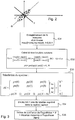
- the axis of weaker variation F and the axis of greater variation G are illustrated on the figure 2 .
- the arrow v along the direction of the axis of weakest variation F corresponds to the standard deviation of the measurements projected on this axis and thus corresponds to an indicator of variations in the axis of rotation.
- the physical measurements comprise N samples at different times according to the three sensitivity axes of the sensor.
- N is greater than or equal to 3.
- a step of constitution E11 of a matrix M is then implemented so that each line corresponds to a temporal sample of the measurements and that each column corresponds to a component obtained along the sensitivity axes X, Y, Z of the sensor.
- a homogenization step E13 is then implemented in order to subtract the average value calculated in step E12 from each element of matrix M.
- the columns of the unitary matrix V are called factorial axes and the sought axis of rotation expressed in the reference associated with the sensors, corresponding to the projection axis on which the measurements have the smallest variance, corresponds to the third column of the unitary matrix V.
- the LAMBDA value (3.3) on the third column of the diagonal matrix LAMBDA corresponds to the variance associated with the axis thus determined.
- the detection method further comprises a calculation step E16 of an indicator of the variations of the axis of rotation.
- d LAMBDA 3.3 LAMBDA 1.1 + LAMBDA 2.2 + LAMBDA 3.3
- This value d of the indicator gives an indication of the validation of the estimated axis of rotation as the invariant rotation axis of the movement.
- the value of LAMBDA (3.3) of the indicator is compared with the value of the noise of the physical measurements obtained by the sensor.
- the value of LAMBDA (3,3) of the indicator is substantially equal to or the same order of magnitude as the value of the noise, the estimated axis of rotation (nx, ny, nz) is validated as a substantially invariant axis of rotation mobile movement.
- LAMBDA (3,3) + LAMBDA (2,2) + LAMBDA (1,1) must be big which guarantees that the movement realized is of sufficient large amplitude.
- d * LAMBDA (3,3) / LAMBDA (2,2) which should be small in front of 1.
- the "constant axis of rotation" hypothesis will be retained only if d * ⁇ threshold that one will take equal to 0.1 for example.
- the least squares method can also be used.
- the method for detecting an axis of rotation described above can be implemented for different types of inertial or magnetic sensors and for example a three-axis sensitivity accelerometer or a three-axis sensitivity magnetometer or still a gyrometer with three axes of sensitivity.
- the estimated axis of rotation corresponds not to the axis of smaller variation, but to the contrary to the axis of greater variation of the measurements.
- the indicator of the variations of the axis of rotation used corresponds then to the variance or the standard deviation, calculated on the two axes orthogonal to the estimated axis of rotation.
- a single inertial or magnetic sensor makes it possible from the physical measurements at the output of this sensor to detect the constant axis of rotation provided that the value of the indicator of the variations in the axis of rotation is substantially equal to the noise value of the associated physical measurements.
- the sensor is an accelerometer
- the standard deviation of the measurements projected on the estimated axis of rotation is substantially equal to the noise of the sensor
- the estimated axis of rotation is validated as a substantially invariant axis of rotation of the motion and the movement is further considered planar.
- the mobile is equipped with several sensors, and for example at least one magnetometer with three axes of sensitivity and an accelerometer with three axes of sensitivity, it is possible to estimate the axis of rotation according to the method described above in the space of physical measurements associated with each of the sensors, that is to say the magnetometer and the accelerometer.
- a linear combination of estimated axes of rotation for the physical measurements of the magnetometer and the accelerometer is then validated as a substantially motion-invariant axis of rotation.
- the coefficients of the linear combination are not strictly between 0 and 1 and their sum is equal to 1.
- the estimate of the axis of rotation will be very bad for the sensor and the detection method will automatically validate the estimated axis of rotation according to the other sensor as rotation axis substantially invariant movement.
- each measure is considered a vector in a three-dimensional space.
- the axis of constant rotation in the measurement space is determined by making the intersection of several planes, each plane corresponding to all possible axes of rotation to move from one vector to another.
- vectors are grouped and analyzed in pairs to determine each plane.
- the distance between the planes at the intersection is an indicator of changes in the axis of rotation.
- this indicator by calculating this indicator and comparing the value of this indicator with the noise value of the physical measurements of the sensor, it is possible to validate the estimated axis of rotation, that is to say the axis corresponding to the intersection of the planes, as axis of substantially invariant rotation of the movement when the value of the indicator is substantially equal to the noise value of the physical measurements of the sensor.
- a recording step E31 makes it possible to acquire physical measurements along the three sensitivity axes of the sensor.
- a calculation step E32 of all solution planes P (t) is then implemented as follows.
- a resolution step E33 of the system is implemented from the construction of a matrix A whose lines correspond to the N samples and the columns to the three components of the vector.
- p : AT px 0 py 0 pz 0 ... ... px NOT - 1 py NOT - 1 pz NOT - 1
- the diagonal terms are ranked in descending order.
- the axis of rotation not ⁇ then corresponds to the third column of the unitary matrix V.
- the estimation of the vector n can be improved, in particular by removing from the matrix the measurements for which mes (t) and mes (0) are close.
- this method of determination by vector analysis can be applied to measurements made from magnetometers in the absence of magnetic disturbances or from measurements obtained at the output of accelerometers in the absence of acceleration.
- the distance between the measurements must be greater than the noise of the measurements.
- the geophysical marker may be typically the NED marker (corresponding to the acronym " North-East-Down” ) .
- the coordinates of the axis of rotation in the geophysical reference frame NED can be calculated from the measurements projected on the axis of rotation expressed in the reference of the sensor in the following manner.
- the magnetic field is variable according to the place of measurement, the values bx and bz being the reference of the terrestrial magnetic field to the place where one made the measurement.
- nz NED mean newmesaccz
- the motion estimation method of a mobile is illustrated in particular in the figure 4 .
- calculation step E42 of the angle of rotation can be implemented as follows.
- a second method could be used by estimating ⁇ by optimization: min ⁇ ⁇ my t - M not ⁇ , ⁇ my 0 ⁇ 2 or M not ⁇ , ⁇ is the rotation matrix of axis n and angle ⁇ .
- the angle of the rotation is the angle formed by the 2 vectors 2D (their coordinates corresponding to the first two columns).
- the acceleration a In the particular case of a planar motion, the acceleration a must be contained in the plane orthogonal to n.
- H H (:, 2: 3) be the matrix made up of the last two columns of H.
- the movement observed may be walking.
- the sensor is placed on the tibial plateau. The precise alignment of the sensor is no longer necessary if one is only interested in the angle described in the sagittal plane of operation.
- the motion estimation method described above can be applied to each time segment corresponding to a stride or a step.
- the axes xb, yb, zb of the predetermined mark Rb are defined by edges of the case 51.
- the calibration method which will be described below makes it possible to determine the rotation matrix making it possible to go from the reference Rc associated with the sensor 50 to the predetermined mark integral with the case Rb.
- the senor 50 can be positioned on an anatomical part, and for example the forearm of an individual.
- the predetermined mark then corresponds to an anatomical mark defined by three axes of anatomical rotation of this anatomical part.
- the axes of the anatomical landmark can be defined by the axes of rotation respectively of a bending movement of the forearm, a movement of prono-supination of the forearm and an abduction movement / adduction of the forearm.
- the calibration method consists of successively rotating according to the three axes of the predetermined mark Rb.
- the calibration method notably comprises acquisition steps E71, E72, E73 of physical measurements by the sensor, respectively corresponding to each rotation around the axes xb, yb, zb of the reference mark Rb.
- N measurement samples are recorded as described above with reference, for example, to the recording step E10 described in FIG. figure 1 .
- a determination step E74, E75, E76 is carried out in order to determine the coordinates of the three axes of rotation n1, n2, n3 corresponding to the axes of the predetermined mark Rb in the reference of the physical measurements. Rc of the sensor.
- a production step E77 of an Rbc matrix is then implemented from the coordinates of the axes of rotation determined in the reference of the physical measurements Rc:
- Rbc [ nx 1 ny 1 nz 1 nx 2 ny 2 nz 2 nx 3 ny 3 nz 3 ]
- the matrix Rbc corresponds to a rotation matrix making it possible to express the measurements of the sensor mark Rc in the predetermined mark Rb integral with the mobile.
- the initial reference may not be orthogonal (the axes are not orthogonal to each other). If the final reference is orthogonal, then the matrix Rbc which makes the change of marker thus makes it possible to pass data expressed in a non-orthogonal reference to data expressed in an orthogonal reference. It is necessary to do this for all three rotations and not orthogonalize the matrix Rbc obtained.
- This method makes it possible to use an inertial unit comprising fewer inertial or magnetic sensors than in the processes of the prior art and in particular without a gyrometer.
- the method for estimating a motion using the detection of a constant axis of rotation is particularly well suited to the case in which the axis of rotation is slowly variable subject to recording the measurement samples N on a window small temporal. It is thus possible to determine, on each time window, the determination of a substantially invariant axis of rotation over this time window provided that there are sufficiently distant measurements from each other over this time window, that is to say having a sufficient distance from the noise of the sensor measurements.
- this distance is less than a predetermined threshold which depends on the noise of the sensors, then the time window is enlarged and a sample of N measurements is re-recorded on this new window.
- the axis of rotation is calculated as indicated above with reference to the method for detecting a substantially invariant axis of rotation and the indicator of variations of this axis. axis of rotation to validate the existence of a constant axis of rotation in the observed motion.
- the angle and the acceleration of the movement on this time window can also be estimated as long as it is desired to observe the movement of a mobile in time.
- the set of operations is then reiterated over a time window shifted in time.
Landscapes
- Engineering & Computer Science (AREA)
- Health & Medical Sciences (AREA)
- Radar, Positioning & Navigation (AREA)
- Remote Sensing (AREA)
- Physics & Mathematics (AREA)
- Life Sciences & Earth Sciences (AREA)
- General Physics & Mathematics (AREA)
- Biophysics (AREA)
- Medical Informatics (AREA)
- Dentistry (AREA)
- Oral & Maxillofacial Surgery (AREA)
- Manufacturing & Machinery (AREA)
- Automation & Control Theory (AREA)
- Pathology (AREA)
- Biomedical Technology (AREA)
- Heart & Thoracic Surgery (AREA)
- Physiology (AREA)
- Molecular Biology (AREA)
- Surgery (AREA)
- Animal Behavior & Ethology (AREA)
- General Health & Medical Sciences (AREA)
- Public Health (AREA)
- Veterinary Medicine (AREA)
- Gyroscopes (AREA)
- Measurement Of Length, Angles, Or The Like Using Electric Or Magnetic Means (AREA)
- Measurement Of The Respiration, Hearing Ability, Form, And Blood Characteristics Of Living Organisms (AREA)
- Length Measuring Devices With Unspecified Measuring Means (AREA)
Claims (7)
- Verfahren zum Ermitteln einer im Wesentlichen invarianten Rotationsachse einer Bewegung eines beweglichen Körpers, der mit mindestens einem Magnetometer mit drei Empfindlichkeitsachsen und einem Beschleunigungsmesser mit drei Empfindlichkeitsachsen versehen ist, umfassend die folgenden Schritte:- Erfassen (E10; E31) physikalischer Messungen entlang der drei Empfindlichkeitsachsen des Magnetometers und des Beschleunigungsmessers, wobei die physikalischen Messungen zumindest drei Abtastungen zu unterschiedlichen Zeitpunkten der Bewegung umfassen;- Schätzen (E11 - E15; E32 - E34) der im Wesentlichen invarianten Rotationsachsen in den Räumen der physikalischen Messungen jeweils des Magnetometers und des Beschleunigungsmessers ausgehend von den zumindest drei erfassten Abtastungen, wobei jede im Wesentlichen invariante Rotationsachse der Achse entspricht, bei der die Standardabweichung der auf die Achse projizierten Werte der physikalischen Messungen minimiert ist, wobei der Schritt des Schätzens umfasst:• einen Schritt des Berechnens (E14) durch Hauptkomponentenanalyse, wobei die dritte Hauptkomponente den Koordinaten der im Wesentlichen invarianten Rotationsachse im Raum der physikalischen Messungen jeweils des Magnetometers und des Beschleunigungsmessers entspricht, oder• einen Schritt des Berechnens der kleinsten Quadrate, der auf eine lineare Kombination der physikalischen Messungen jeweils des Magnetometers und des Beschleunigungsmessers angewendet wird;- Berechnen (E16; E35) eines Indikators (d) der Änderungen der jeweils geschätzten Rotationsachse für den Beschleunigungsmesser und das Magnetometer; und- Validieren einer linearen Kombination der geschätzten Rotationsachsen für die physikalischen Messungen von Magnetometer und Beschleunigungsmesser als im Wesentlichen invariante Rotationsachse der Bewegung, wobei die Koeffizienten der Kombination nicht streng zwischen 0 und 1 liegen, ihre Summe gleich 1 ist, und sie Funktion der Werte der Indikatoren der Änderungen der Rotationsachsen des Magnetometers und/oder des Beschleunigungsmessers sind.
- Ermittlungsverfahren nach Anspruch 1, ferner umfassend die nachfolgenden Schritte:- Vergleichen (E16; E35) des Werts eines jeden Indikators mit einem vorbestimmten Schwellwert; und- Validieren der jeweils geschätzten Rotationsachse für den Beschleunigungsmesser und das Magnetometer als im Wesentlichen invariante Rotationsachse der Bewegung dann, wenn der Wert des Indikators (d) kleiner als der vorbestimmte Schwellwert ist, wobei der Schwellenwert vorteilhaft gleich dem Rauschwert der physikalischen Messungen jeweils des Beschleunigungsmessers und des Magnetometers ist.
- Ermittlungsverfahren nach einem der vorangehenden Ansprüche, wobei dann, wenn für den Beschleunigungsmesser und das Magnetometer die Standardabweichung im Wesentlichen gleich der Standardabweichung des Rauschens von Beschleunigungsmesser bzw. Magnetometer ist, die geschätzte Rotationsachse als im Wesentlichen invariante Rotationsachse der Bewegung validiert wird.
- Ermittlungsverfahren nach einem der vorangehenden Ansprüche, ferner umfassend jeweils für den Beschleunigungsmesser und das Magnetometer einen Schritt der Transformation der Koordinaten der geschätzten Rotationsachse in dem Messbezugssystem des Sensors in Koordinaten in einem geophysikalischen Bezugssystem.
- Verfahren zum Schätzen einer Bewegung eines beweglichen Körpers, der mit mindestens einem Magnetometer mit drei Empfindlichkeitsachsen und einem Beschleunigungsmesser mit drei Empfindlichkeitsachsen versehen ist, wobei die Bewegung eine Drehung um eine im Wesentlichen invariante Achse umfasst, dadurch gekennzeichnet, dass es die nachfolgenden Schritte umfasst:- Ermitteln (E41) einer im Wesentlichen invarianten Rotationsachse mit dem Ermittlungsverfahren nach einem der Ansprüche 1 bis 4;- Bestimmen (E42) des Rotationswinkels des beweglichen Körpers um die im Wesentlichen invariante Rotationsachse.
- Schätzungsverfahren nach Anspruch 5, ferner umfassend einen Schritt des Bestimmens (E43) der Beschleunigung des beweglichen Körpers.
- Vorrichtung zum Ermitteln einer im Wesentlichen invarianten Rotationsachse einer Bewegung eines beweglichen Körpers, der mit zumindest einem Magnetometer mit drei Empfindlichkeitsachsen und einem Beschleunigungsmesser mit drei Empfindlichkeitsachsen versehen ist, enthaltend Einrichtungen, die dazu geeignet sind, das Ermittlungsverfahren nach einem der Ansprüche 1 bis 4 durchzuführen.
Priority Applications (1)
| Application Number | Priority Date | Filing Date | Title |
|---|---|---|---|
| EP18173359.3A EP3381367B1 (de) | 2007-04-25 | 2008-04-21 | Verfahren und vorrichtung zum kalibrieren eines trägheits- oder magnetsensors mit drei sensibilitätsachsen |
Applications Claiming Priority (1)
| Application Number | Priority Date | Filing Date | Title |
|---|---|---|---|
| FR0754693A FR2915568B1 (fr) | 2007-04-25 | 2007-04-25 | Procede et dispositif de detection d'un axe de rotation sensiblement invariant |
Related Child Applications (2)
| Application Number | Title | Priority Date | Filing Date |
|---|---|---|---|
| EP18173359.3A Division EP3381367B1 (de) | 2007-04-25 | 2008-04-21 | Verfahren und vorrichtung zum kalibrieren eines trägheits- oder magnetsensors mit drei sensibilitätsachsen |
| EP18173359.3A Division-Into EP3381367B1 (de) | 2007-04-25 | 2008-04-21 | Verfahren und vorrichtung zum kalibrieren eines trägheits- oder magnetsensors mit drei sensibilitätsachsen |
Publications (2)
| Publication Number | Publication Date |
|---|---|
| EP1985233A1 EP1985233A1 (de) | 2008-10-29 |
| EP1985233B1 true EP1985233B1 (de) | 2018-07-18 |
Family
ID=38740199
Family Applications (2)
| Application Number | Title | Priority Date | Filing Date |
|---|---|---|---|
| EP08290390.7A Active EP1985233B1 (de) | 2007-04-25 | 2008-04-21 | Verfahren und Vorrichtung zur Erfassung einer extrem unveränderlichen Drehachse |
| EP18173359.3A Active EP3381367B1 (de) | 2007-04-25 | 2008-04-21 | Verfahren und vorrichtung zum kalibrieren eines trägheits- oder magnetsensors mit drei sensibilitätsachsen |
Family Applications After (1)
| Application Number | Title | Priority Date | Filing Date |
|---|---|---|---|
| EP18173359.3A Active EP3381367B1 (de) | 2007-04-25 | 2008-04-21 | Verfahren und vorrichtung zum kalibrieren eines trägheits- oder magnetsensors mit drei sensibilitätsachsen |
Country Status (4)
| Country | Link |
|---|---|
| US (1) | US7890291B2 (de) |
| EP (2) | EP1985233B1 (de) |
| JP (1) | JP5594940B2 (de) |
| FR (1) | FR2915568B1 (de) |
Families Citing this family (53)
| Publication number | Priority date | Publication date | Assignee | Title |
|---|---|---|---|---|
| JP4935427B2 (ja) * | 2007-03-01 | 2012-05-23 | ヤマハ株式会社 | 磁気データ処理装置、方法およびプログラムならびに磁気処理システム。 |
| US8206325B1 (en) | 2007-10-12 | 2012-06-26 | Biosensics, L.L.C. | Ambulatory system for measuring and monitoring physical activity and risk of falling and for automatic fall detection |
| FR2926971B1 (fr) * | 2008-02-04 | 2011-02-25 | Commissariat Energie Atomique | Dispositif d'analyse de la marche |
| US8223121B2 (en) * | 2008-10-20 | 2012-07-17 | Sensor Platforms, Inc. | Host system and method for determining an attitude of a device undergoing dynamic acceleration |
| EP2381845B1 (de) | 2009-01-05 | 2019-09-11 | Movea S.A | Vorrichtung, verfahren und systeme zur charakterisierung von fussbewegungen |
| US8515707B2 (en) * | 2009-01-07 | 2013-08-20 | Sensor Platforms, Inc. | System and method for determining an attitude of a device undergoing dynamic acceleration using a Kalman filter |
| US8587519B2 (en) * | 2009-01-07 | 2013-11-19 | Sensor Platforms, Inc. | Rolling gesture detection using a multi-dimensional pointing device |
| FR2943424B1 (fr) * | 2009-03-23 | 2011-06-10 | Radiotelephone Sfr | Procede d'identification d'un axe rotation unique d'un mouvement de rotation |
| US20100318257A1 (en) * | 2009-06-15 | 2010-12-16 | Deep Kalinadhabhotla | Method and system for automatically calibrating a three-axis accelerometer device |
| FR2948802B1 (fr) * | 2009-07-29 | 2014-12-05 | Movea | Systeme et procede de comptage d'un deplacement elementaire d'une personne |
| FR2948759B1 (fr) * | 2009-07-31 | 2011-08-12 | Movea | Procede d'estimation de l'orientation d'un solide en mouvement |
| JP2011169656A (ja) * | 2010-02-17 | 2011-09-01 | Alps Electric Co Ltd | 磁界検知装置 |
| US8979665B1 (en) | 2010-03-22 | 2015-03-17 | Bijan Najafi | Providing motion feedback based on user center of mass |
| FR2959112B1 (fr) * | 2010-04-23 | 2015-05-29 | Movea | Systeme d'analyse de foulees d'un utilisateur |
| NL2005261C2 (en) | 2010-08-24 | 2012-02-27 | Solland Solar Cells B V | Back contacted photovoltaic cell with an improved shunt resistance. |
| US8957909B2 (en) | 2010-10-07 | 2015-02-17 | Sensor Platforms, Inc. | System and method for compensating for drift in a display of a user interface state |
| US8753275B2 (en) | 2011-01-13 | 2014-06-17 | BioSensics LLC | Intelligent device to monitor and remind patients with footwear, walking aids, braces, or orthotics |
| US8914037B2 (en) | 2011-08-11 | 2014-12-16 | Qualcomm Incorporated | Numerically stable computation of heading without a reference axis |
| US20130046505A1 (en) * | 2011-08-15 | 2013-02-21 | Qualcomm Incorporated | Methods and apparatuses for use in classifying a motion state of a mobile device |
| FR2985583B1 (fr) | 2012-01-06 | 2014-01-17 | Movea | Dispositif de commande gestuelle d'un systeme, et procede associe |
| US9459276B2 (en) | 2012-01-06 | 2016-10-04 | Sensor Platforms, Inc. | System and method for device self-calibration |
| WO2013104006A2 (en) | 2012-01-08 | 2013-07-11 | Sensor Platforms, Inc. | System and method for calibrating sensors for different operating environments |
| FR2987735B1 (fr) | 2012-03-08 | 2014-04-11 | Movea | Procede d'identification des parametres geometriques d'une structure articulee et d'un ensemble de reperes d'interet disposes sur ladite structure |
| US9228842B2 (en) | 2012-03-25 | 2016-01-05 | Sensor Platforms, Inc. | System and method for determining a uniform external magnetic field |
| US10922383B2 (en) | 2012-04-13 | 2021-02-16 | Adidas Ag | Athletic activity monitoring methods and systems |
| US9257054B2 (en) | 2012-04-13 | 2016-02-09 | Adidas Ag | Sport ball athletic activity monitoring methods and systems |
| US9737261B2 (en) | 2012-04-13 | 2017-08-22 | Adidas Ag | Wearable athletic activity monitoring systems |
| US9504414B2 (en) | 2012-04-13 | 2016-11-29 | Adidas Ag | Wearable athletic activity monitoring methods and systems |
| US9726498B2 (en) | 2012-11-29 | 2017-08-08 | Sensor Platforms, Inc. | Combining monitoring sensor measurements and system signals to determine device context |
| FR2999699B1 (fr) | 2012-12-19 | 2015-12-11 | Commissariat Energie Atomique | Procede de determination de l'inclinaison d'un objet |
| US20140278225A1 (en) * | 2013-03-12 | 2014-09-18 | Novatel Wireless, Inc. | Determining changes in physical location based on the observed magnetic field |
| US9500464B2 (en) | 2013-03-12 | 2016-11-22 | Adidas Ag | Methods of determining performance information for individuals and sports objects |
| US9311789B1 (en) | 2013-04-09 | 2016-04-12 | BioSensics LLC | Systems and methods for sensorimotor rehabilitation |
| US10320073B2 (en) * | 2014-01-14 | 2019-06-11 | Viasat, Inc. | Mobile terminal antenna alignment using arbitrary orientation attitude |
| US20150286279A1 (en) * | 2014-04-07 | 2015-10-08 | InvenSense, Incorporated | Systems and methods for guiding a user during calibration of a sensor |
| US9849361B2 (en) | 2014-05-14 | 2017-12-26 | Adidas Ag | Sports ball athletic activity monitoring methods and systems |
| US10523053B2 (en) | 2014-05-23 | 2019-12-31 | Adidas Ag | Sport ball inductive charging methods and systems |
| US9710711B2 (en) | 2014-06-26 | 2017-07-18 | Adidas Ag | Athletic activity heads up display systems and methods |
| US11562417B2 (en) | 2014-12-22 | 2023-01-24 | Adidas Ag | Retail store motion sensor systems and methods |
| JP6448458B2 (ja) * | 2015-05-08 | 2019-01-09 | 株式会社Nttドコモ | 回転状態算出装置 |
| JP6448459B2 (ja) * | 2015-05-08 | 2019-01-09 | 株式会社Nttドコモ | 回転状態算出装置 |
| DE102016109153A1 (de) * | 2016-05-18 | 2017-11-23 | Fraunhofer-Gesellschaft zur Förderung der angewandten Forschung e.V. | Verfahren zum einstellen einer blickrichtung in einer darstellung einer virtuellen umgebung |
| US10041800B2 (en) | 2016-09-23 | 2018-08-07 | Qualcomm Incorporated | Pedestrian sensor assistance in a mobile device during typical device motions |
| US10211508B2 (en) | 2017-07-06 | 2019-02-19 | Viasat, Inc. | Dynamic antenna platform offset calibration |
| FR3080186B1 (fr) | 2018-04-16 | 2020-05-08 | Commissariat A L'energie Atomique Et Aux Energies Alternatives | Procede de calibration d'un reseau de magnetometres |
| GB2574074B (en) | 2018-07-27 | 2020-05-20 | Mclaren Applied Tech Ltd | Time synchronisation |
| FR3095041B1 (fr) * | 2019-04-15 | 2021-03-19 | Commissariat Energie Atomique | Procede de determination de la position et de l'orientation d'un vehicule |
| US11435376B2 (en) * | 2019-06-28 | 2022-09-06 | Sstatzz Oy | Method for determining a direction of a spin axis of a rotating apparatus |
| US11118893B2 (en) | 2019-06-28 | 2021-09-14 | Sstatzz Oy | Method for determining a direction of a spin axis of a rotating apparatus |
| GB2588236B (en) | 2019-10-18 | 2024-03-20 | Mclaren Applied Ltd | Gyroscope bias estimation |
| CN112461224B (zh) * | 2020-11-10 | 2021-09-14 | 武汉大学 | 一种基于已知姿态角的磁力计标定方法 |
| FR3116334B1 (fr) | 2020-11-17 | 2023-01-13 | Commissariat Energie Atomique | Procédé d’alignement d’une pluralité de capteurs inertiels et/ou magnétiques et dispositif permettant la mise en œuvre d’un tel procédé |
| US20230181060A1 (en) * | 2021-12-13 | 2023-06-15 | Koneksa Health Inc. | Measuring method and device |
Citations (1)
| Publication number | Priority date | Publication date | Assignee | Title |
|---|---|---|---|---|
| EP1965169A2 (de) * | 2007-03-01 | 2008-09-03 | Yamaha Corporation | Magnetische Datenverarbeitungsvorrichtung, entsprechendes Verfahren und Programm sowie Magnetverarbeitungssystem |
Family Cites Families (7)
| Publication number | Priority date | Publication date | Assignee | Title |
|---|---|---|---|---|
| US3731521A (en) * | 1971-09-08 | 1973-05-08 | Singer Co | System and method for monitoring the performance of a dual platform inertial navigation system |
| DE3734941A1 (de) * | 1987-10-15 | 1989-04-27 | Messerschmitt Boelkow Blohm | Verfahren zur kalibrierung der kreisel eines dreiachsenstabilisierten satelliten |
| US5105152A (en) * | 1990-03-22 | 1992-04-14 | The Board Of Trustees Of The Leland Stanford Junior University | Magnetic resonance imaging and spectroscopy using a linear class of large tip-angle selective excitation pulses |
| JPH11248456A (ja) * | 1998-02-27 | 1999-09-17 | Olympus Optical Co Ltd | 3軸姿勢検出装置 |
| AU2002230578A1 (en) * | 2000-10-30 | 2002-05-15 | Naval Postgraduate School | Method and apparatus for motion tracking of an articulated rigid body |
| FR2838185B1 (fr) * | 2002-04-05 | 2004-08-06 | Commissariat Energie Atomique | Dispositif de capture des mouvements de rotation d'un solide |
| WO2007099599A1 (ja) * | 2006-02-28 | 2007-09-07 | Aichi Micro Intelligent Corporation | 磁気式ジャイロ |
-
2007
- 2007-04-25 FR FR0754693A patent/FR2915568B1/fr active Active
-
2008
- 2008-04-21 EP EP08290390.7A patent/EP1985233B1/de active Active
- 2008-04-21 EP EP18173359.3A patent/EP3381367B1/de active Active
- 2008-04-24 JP JP2008113479A patent/JP5594940B2/ja not_active Expired - Fee Related
- 2008-04-24 US US12/108,981 patent/US7890291B2/en active Active
Patent Citations (1)
| Publication number | Priority date | Publication date | Assignee | Title |
|---|---|---|---|---|
| EP1965169A2 (de) * | 2007-03-01 | 2008-09-03 | Yamaha Corporation | Magnetische Datenverarbeitungsvorrichtung, entsprechendes Verfahren und Programm sowie Magnetverarbeitungssystem |
Also Published As
| Publication number | Publication date |
|---|---|
| EP1985233A1 (de) | 2008-10-29 |
| JP5594940B2 (ja) | 2014-09-24 |
| US7890291B2 (en) | 2011-02-15 |
| JP2009002934A (ja) | 2009-01-08 |
| US20080281555A1 (en) | 2008-11-13 |
| EP3381367B1 (de) | 2022-02-02 |
| FR2915568A1 (fr) | 2008-10-31 |
| EP3381367A1 (de) | 2018-10-03 |
| FR2915568B1 (fr) | 2009-07-31 |
Similar Documents
| Publication | Publication Date | Title |
|---|---|---|
| EP1985233B1 (de) | Verfahren und Vorrichtung zur Erfassung einer extrem unveränderlichen Drehachse | |
| EP2718670B1 (de) | Vereinfachtes verfahren zur schätzung der ausrichtung eines objekts und lagesensor zur durchführung dieses verfahrens | |
| EP3658921B1 (de) | Verfahren zur kalibrierung eines magnetometers | |
| EP3623758B1 (de) | Standortbestimmungssystem und entsprechendes standortbestimmungsverfahren | |
| EP3213033B1 (de) | Verfahren zur schätzung eines navigationszustands, der in bezug auf beobachtbarkeit eingeschränkt ist | |
| EP2459966B1 (de) | Verfahren zur schätzung der richtung eines beweglichen festkörpers | |
| EP3680615B1 (de) | Bestimmungsverfahren eines schutzradius eines sichtgestützten navigationssystems | |
| EP1990138A1 (de) | Datenverarbeitungsverfahren zur Bewegungserfassung einer Gelenkstruktur | |
| EP2428934B1 (de) | Verfahren zur Schätzung der Bewegung eines Trägers im Verhältnis zu einer Umgebung, und Berechnungsvorrichtung für ein Navigationssystem | |
| EP2494366B1 (de) | System und verfahren zur zählung der richtungsänderungen einer person | |
| EP2502202B1 (de) | Verfahren zur schätzung der bewegung eines über einen himmelskörper fliegenden beobachtungsinstruments | |
| EP2350565A1 (de) | Einrichtung und verfahren zum bestimmen eines charakteristikums eines durch aufeinanderfolgende positionen eines starr mit einem mobilen element verbundenen triaxialbeschleunigungsmessers gebildeten pfads | |
| EP3807595B1 (de) | Verfahren zum kalibrieren eines in einem objekt eingebauten gyrometers | |
| EP3655800B1 (de) | Verfahren und vorrichtung zur magnetfeldmessung durch magnetometer | |
| EP2405399B1 (de) | Eichungsverfahren zur Ausrichtung einer Onboard-Videokamera | |
| WO2017153690A1 (fr) | Procédé de détection d'une anomalie dans le cadre de l'utilisation d'un dispositif de localisation magnétique | |
| WO2014095476A1 (fr) | Procede iteratif de determination d'un biais d'un capteur de mesure d'un champ physique vectoriel sensiblement continu | |
| EP1969314B1 (de) | Verfahren zur schätzung einer bewegung eines festkörpers | |
| EP3655724B1 (de) | Verfahren zur schätzung der bewegung eines sich in einem magnetfeld bewegenden objekts | |
| EP2822462A1 (de) | Verfahren zur identifizierung der geometrischen parameter einer gelenkstruktur und set aus bestimmten, auf dieser struktur angeordneten referenzbildern | |
| EP4001851A1 (de) | Verfahren zur ausrichtung einer vielzahl von trägheits- und/oder magnetischen sensoren und vorrichtung zur durchführung eines solchen verfahrens | |
| EP3072110B1 (de) | Verfahren zur schätzung der bewegung eines objekts | |
| CN117804442A (zh) | 飞行器的位姿确定方法、装置、电子设备及存储介质 |
Legal Events
| Date | Code | Title | Description |
|---|---|---|---|
| PUAI | Public reference made under article 153(3) epc to a published international application that has entered the european phase |
Free format text: ORIGINAL CODE: 0009012 |
|
| AK | Designated contracting states |
Kind code of ref document: A1 Designated state(s): AT BE BG CH CY CZ DE DK EE ES FI FR GB GR HR HU IE IS IT LI LT LU LV MC MT NL NO PL PT RO SE SI SK TR |
|
| AX | Request for extension of the european patent |
Extension state: AL BA MK RS |
|
| 17P | Request for examination filed |
Effective date: 20090423 |
|
| 17Q | First examination report despatched |
Effective date: 20090527 |
|
| AKX | Designation fees paid |
Designated state(s): AT BE BG CH CY CZ DE DK EE ES FI FR GB GR HR HU IE IS IT LI LT LU LV MC MT NL NO PL PT RO SE SI SK TR |
|
| RAP1 | Party data changed (applicant data changed or rights of an application transferred) |
Owner name: COMMISSARIAT A L'ENERGIE ATOMIQUE ET AUX ENERGIES |
|
| REG | Reference to a national code |
Ref country code: DE Ref legal event code: R079 Ref document number: 602008056043 Country of ref document: DE Free format text: PREVIOUS MAIN CLASS: A61B0005110000 Ipc: G01C0021160000 |
|
| RIC1 | Information provided on ipc code assigned before grant |
Ipc: G01C 21/16 20060101AFI20171004BHEP |
|
| GRAP | Despatch of communication of intention to grant a patent |
Free format text: ORIGINAL CODE: EPIDOSNIGR1 |
|
| STAA | Information on the status of an ep patent application or granted ep patent |
Free format text: STATUS: GRANT OF PATENT IS INTENDED |
|
| INTG | Intention to grant announced |
Effective date: 20171212 |
|
| GRAS | Grant fee paid |
Free format text: ORIGINAL CODE: EPIDOSNIGR3 |
|
| GRAA | (expected) grant |
Free format text: ORIGINAL CODE: 0009210 |
|
| STAA | Information on the status of an ep patent application or granted ep patent |
Free format text: STATUS: THE PATENT HAS BEEN GRANTED |
|
| RAP1 | Party data changed (applicant data changed or rights of an application transferred) |
Owner name: UNIVERSITE JOSEPH FOURIER Owner name: COMMISSARIAT A L'ENERGIE ATOMIQUE ET AUX ENERGIES Owner name: INSTITUT NATIONAL POLYTECHNIQUE DE GRENOBLE |
|
| RAP1 | Party data changed (applicant data changed or rights of an application transferred) |
Owner name: COMMISSARIAT A L'ENERGIE ATOMIQUE ET AUX ENERGIES |
|
| AK | Designated contracting states |
Kind code of ref document: B1 Designated state(s): AT BE BG CH CY CZ DE DK EE ES FI FR GB GR HR HU IE IS IT LI LT LU LV MC MT NL NO PL PT RO SE SI SK TR |
|
| REG | Reference to a national code |
Ref country code: GB Ref legal event code: FG4D Free format text: NOT ENGLISH |
|
| REG | Reference to a national code |
Ref country code: CH Ref legal event code: EP |
|
| REG | Reference to a national code |
Ref country code: IE Ref legal event code: FG4D Free format text: LANGUAGE OF EP DOCUMENT: FRENCH |
|
| REG | Reference to a national code |
Ref country code: AT Ref legal event code: REF Ref document number: 1019863 Country of ref document: AT Kind code of ref document: T Effective date: 20180815 |
|
| REG | Reference to a national code |
Ref country code: DE Ref legal event code: R096 Ref document number: 602008056043 Country of ref document: DE |
|
| REG | Reference to a national code |
Ref country code: NL Ref legal event code: MP Effective date: 20180718 |
|
| REG | Reference to a national code |
Ref country code: LT Ref legal event code: MG4D |
|
| REG | Reference to a national code |
Ref country code: AT Ref legal event code: MK05 Ref document number: 1019863 Country of ref document: AT Kind code of ref document: T Effective date: 20180718 |
|
| PG25 | Lapsed in a contracting state [announced via postgrant information from national office to epo] |
Ref country code: NL Free format text: LAPSE BECAUSE OF FAILURE TO SUBMIT A TRANSLATION OF THE DESCRIPTION OR TO PAY THE FEE WITHIN THE PRESCRIBED TIME-LIMIT Effective date: 20180718 |
|
| PG25 | Lapsed in a contracting state [announced via postgrant information from national office to epo] |
Ref country code: FI Free format text: LAPSE BECAUSE OF FAILURE TO SUBMIT A TRANSLATION OF THE DESCRIPTION OR TO PAY THE FEE WITHIN THE PRESCRIBED TIME-LIMIT Effective date: 20180718 Ref country code: PL Free format text: LAPSE BECAUSE OF FAILURE TO SUBMIT A TRANSLATION OF THE DESCRIPTION OR TO PAY THE FEE WITHIN THE PRESCRIBED TIME-LIMIT Effective date: 20180718 Ref country code: BG Free format text: LAPSE BECAUSE OF FAILURE TO SUBMIT A TRANSLATION OF THE DESCRIPTION OR TO PAY THE FEE WITHIN THE PRESCRIBED TIME-LIMIT Effective date: 20181018 Ref country code: SE Free format text: LAPSE BECAUSE OF FAILURE TO SUBMIT A TRANSLATION OF THE DESCRIPTION OR TO PAY THE FEE WITHIN THE PRESCRIBED TIME-LIMIT Effective date: 20180718 Ref country code: AT Free format text: LAPSE BECAUSE OF FAILURE TO SUBMIT A TRANSLATION OF THE DESCRIPTION OR TO PAY THE FEE WITHIN THE PRESCRIBED TIME-LIMIT Effective date: 20180718 Ref country code: NO Free format text: LAPSE BECAUSE OF FAILURE TO SUBMIT A TRANSLATION OF THE DESCRIPTION OR TO PAY THE FEE WITHIN THE PRESCRIBED TIME-LIMIT Effective date: 20181018 Ref country code: LT Free format text: LAPSE BECAUSE OF FAILURE TO SUBMIT A TRANSLATION OF THE DESCRIPTION OR TO PAY THE FEE WITHIN THE PRESCRIBED TIME-LIMIT Effective date: 20180718 Ref country code: GR Free format text: LAPSE BECAUSE OF FAILURE TO SUBMIT A TRANSLATION OF THE DESCRIPTION OR TO PAY THE FEE WITHIN THE PRESCRIBED TIME-LIMIT Effective date: 20181019 Ref country code: IS Free format text: LAPSE BECAUSE OF FAILURE TO SUBMIT A TRANSLATION OF THE DESCRIPTION OR TO PAY THE FEE WITHIN THE PRESCRIBED TIME-LIMIT Effective date: 20181118 |
|
| PG25 | Lapsed in a contracting state [announced via postgrant information from national office to epo] |
Ref country code: HR Free format text: LAPSE BECAUSE OF FAILURE TO SUBMIT A TRANSLATION OF THE DESCRIPTION OR TO PAY THE FEE WITHIN THE PRESCRIBED TIME-LIMIT Effective date: 20180718 Ref country code: ES Free format text: LAPSE BECAUSE OF FAILURE TO SUBMIT A TRANSLATION OF THE DESCRIPTION OR TO PAY THE FEE WITHIN THE PRESCRIBED TIME-LIMIT Effective date: 20180718 Ref country code: LV Free format text: LAPSE BECAUSE OF FAILURE TO SUBMIT A TRANSLATION OF THE DESCRIPTION OR TO PAY THE FEE WITHIN THE PRESCRIBED TIME-LIMIT Effective date: 20180718 |
|
| REG | Reference to a national code |
Ref country code: DE Ref legal event code: R097 Ref document number: 602008056043 Country of ref document: DE |
|
| PG25 | Lapsed in a contracting state [announced via postgrant information from national office to epo] |
Ref country code: CZ Free format text: LAPSE BECAUSE OF FAILURE TO SUBMIT A TRANSLATION OF THE DESCRIPTION OR TO PAY THE FEE WITHIN THE PRESCRIBED TIME-LIMIT Effective date: 20180718 Ref country code: EE Free format text: LAPSE BECAUSE OF FAILURE TO SUBMIT A TRANSLATION OF THE DESCRIPTION OR TO PAY THE FEE WITHIN THE PRESCRIBED TIME-LIMIT Effective date: 20180718 Ref country code: RO Free format text: LAPSE BECAUSE OF FAILURE TO SUBMIT A TRANSLATION OF THE DESCRIPTION OR TO PAY THE FEE WITHIN THE PRESCRIBED TIME-LIMIT Effective date: 20180718 Ref country code: IT Free format text: LAPSE BECAUSE OF FAILURE TO SUBMIT A TRANSLATION OF THE DESCRIPTION OR TO PAY THE FEE WITHIN THE PRESCRIBED TIME-LIMIT Effective date: 20180718 |
|
| PLBE | No opposition filed within time limit |
Free format text: ORIGINAL CODE: 0009261 |
|
| STAA | Information on the status of an ep patent application or granted ep patent |
Free format text: STATUS: NO OPPOSITION FILED WITHIN TIME LIMIT |
|
| PG25 | Lapsed in a contracting state [announced via postgrant information from national office to epo] |
Ref country code: DK Free format text: LAPSE BECAUSE OF FAILURE TO SUBMIT A TRANSLATION OF THE DESCRIPTION OR TO PAY THE FEE WITHIN THE PRESCRIBED TIME-LIMIT Effective date: 20180718 Ref country code: SK Free format text: LAPSE BECAUSE OF FAILURE TO SUBMIT A TRANSLATION OF THE DESCRIPTION OR TO PAY THE FEE WITHIN THE PRESCRIBED TIME-LIMIT Effective date: 20180718 |
|
| 26N | No opposition filed |
Effective date: 20190423 |
|
| PG25 | Lapsed in a contracting state [announced via postgrant information from national office to epo] |
Ref country code: SI Free format text: LAPSE BECAUSE OF FAILURE TO SUBMIT A TRANSLATION OF THE DESCRIPTION OR TO PAY THE FEE WITHIN THE PRESCRIBED TIME-LIMIT Effective date: 20180718 |
|
| REG | Reference to a national code |
Ref country code: CH Ref legal event code: PL |
|
| REG | Reference to a national code |
Ref country code: BE Ref legal event code: MM Effective date: 20190430 |
|
| PG25 | Lapsed in a contracting state [announced via postgrant information from national office to epo] |
Ref country code: LU Free format text: LAPSE BECAUSE OF NON-PAYMENT OF DUE FEES Effective date: 20190421 Ref country code: MC Free format text: LAPSE BECAUSE OF FAILURE TO SUBMIT A TRANSLATION OF THE DESCRIPTION OR TO PAY THE FEE WITHIN THE PRESCRIBED TIME-LIMIT Effective date: 20180718 |
|
| PG25 | Lapsed in a contracting state [announced via postgrant information from national office to epo] |
Ref country code: CH Free format text: LAPSE BECAUSE OF NON-PAYMENT OF DUE FEES Effective date: 20190430 Ref country code: LI Free format text: LAPSE BECAUSE OF NON-PAYMENT OF DUE FEES Effective date: 20190430 |
|
| PG25 | Lapsed in a contracting state [announced via postgrant information from national office to epo] |
Ref country code: BE Free format text: LAPSE BECAUSE OF NON-PAYMENT OF DUE FEES Effective date: 20190430 |
|
| PG25 | Lapsed in a contracting state [announced via postgrant information from national office to epo] |
Ref country code: TR Free format text: LAPSE BECAUSE OF FAILURE TO SUBMIT A TRANSLATION OF THE DESCRIPTION OR TO PAY THE FEE WITHIN THE PRESCRIBED TIME-LIMIT Effective date: 20180718 |
|
| PG25 | Lapsed in a contracting state [announced via postgrant information from national office to epo] |
Ref country code: IE Free format text: LAPSE BECAUSE OF NON-PAYMENT OF DUE FEES Effective date: 20190421 |
|
| PG25 | Lapsed in a contracting state [announced via postgrant information from national office to epo] |
Ref country code: PT Free format text: LAPSE BECAUSE OF FAILURE TO SUBMIT A TRANSLATION OF THE DESCRIPTION OR TO PAY THE FEE WITHIN THE PRESCRIBED TIME-LIMIT Effective date: 20181118 |
|
| PG25 | Lapsed in a contracting state [announced via postgrant information from national office to epo] |
Ref country code: CY Free format text: LAPSE BECAUSE OF FAILURE TO SUBMIT A TRANSLATION OF THE DESCRIPTION OR TO PAY THE FEE WITHIN THE PRESCRIBED TIME-LIMIT Effective date: 20180718 |
|
| PG25 | Lapsed in a contracting state [announced via postgrant information from national office to epo] |
Ref country code: HU Free format text: LAPSE BECAUSE OF FAILURE TO SUBMIT A TRANSLATION OF THE DESCRIPTION OR TO PAY THE FEE WITHIN THE PRESCRIBED TIME-LIMIT; INVALID AB INITIO Effective date: 20080421 Ref country code: MT Free format text: LAPSE BECAUSE OF FAILURE TO SUBMIT A TRANSLATION OF THE DESCRIPTION OR TO PAY THE FEE WITHIN THE PRESCRIBED TIME-LIMIT Effective date: 20180718 |
|
| PGFP | Annual fee paid to national office [announced via postgrant information from national office to epo] |
Ref country code: DE Payment date: 20250417 Year of fee payment: 18 |
|
| PGFP | Annual fee paid to national office [announced via postgrant information from national office to epo] |
Ref country code: GB Payment date: 20250424 Year of fee payment: 18 |
|
| PGFP | Annual fee paid to national office [announced via postgrant information from national office to epo] |
Ref country code: FR Payment date: 20250422 Year of fee payment: 18 |