EP1984591B1 - Kombinationsschloss für druckknopf - Google Patents
Kombinationsschloss für druckknopf Download PDFInfo
- Publication number
- EP1984591B1 EP1984591B1 EP20060830611 EP06830611A EP1984591B1 EP 1984591 B1 EP1984591 B1 EP 1984591B1 EP 20060830611 EP20060830611 EP 20060830611 EP 06830611 A EP06830611 A EP 06830611A EP 1984591 B1 EP1984591 B1 EP 1984591B1
- Authority
- EP
- European Patent Office
- Prior art keywords
- lock
- tumbler
- slide
- check
- series
- Prior art date
- Legal status (The legal status is an assumption and is not a legal conclusion. Google has not performed a legal analysis and makes no representation as to the accuracy of the status listed.)
- Active
Links
Images


Classifications
-
- E—FIXED CONSTRUCTIONS
- E05—LOCKS; KEYS; WINDOW OR DOOR FITTINGS; SAFES
- E05B—LOCKS; ACCESSORIES THEREFOR; HANDCUFFS
- E05B37/00—Permutation or combination locks; Puzzle locks
- E05B37/16—Permutation or combination locks; Puzzle locks with two or more push or pull knobs, slides, or the like
-
- E—FIXED CONSTRUCTIONS
- E05—LOCKS; KEYS; WINDOW OR DOOR FITTINGS; SAFES
- E05B—LOCKS; ACCESSORIES THEREFOR; HANDCUFFS
- E05B13/00—Devices preventing the key or the handle or both from being used
- E05B13/002—Devices preventing the key or the handle or both from being used locking the handle
-
- E—FIXED CONSTRUCTIONS
- E05—LOCKS; KEYS; WINDOW OR DOOR FITTINGS; SAFES
- E05B—LOCKS; ACCESSORIES THEREFOR; HANDCUFFS
- E05B63/00—Locks or fastenings with special structural characteristics
- E05B63/04—Locks or fastenings with special structural characteristics for alternative use on the right-hand or left-hand side of wings
-
- E—FIXED CONSTRUCTIONS
- E05—LOCKS; KEYS; WINDOW OR DOOR FITTINGS; SAFES
- E05B—LOCKS; ACCESSORIES THEREFOR; HANDCUFFS
- E05B63/00—Locks or fastenings with special structural characteristics
- E05B63/06—Locks or fastenings with special structural characteristics with lengthwise-adjustable bolts ; with adjustable backset, i.e. distance from door edge
-
- Y—GENERAL TAGGING OF NEW TECHNOLOGICAL DEVELOPMENTS; GENERAL TAGGING OF CROSS-SECTIONAL TECHNOLOGIES SPANNING OVER SEVERAL SECTIONS OF THE IPC; TECHNICAL SUBJECTS COVERED BY FORMER USPC CROSS-REFERENCE ART COLLECTIONS [XRACs] AND DIGESTS
- Y10—TECHNICAL SUBJECTS COVERED BY FORMER USPC
- Y10T—TECHNICAL SUBJECTS COVERED BY FORMER US CLASSIFICATION
- Y10T70/00—Locks
- Y10T70/50—Special application
- Y10T70/5611—For control and machine elements
- Y10T70/5757—Handle, handwheel or knob
- Y10T70/5765—Rotary or swinging
- Y10T70/577—Locked stationary
- Y10T70/5783—Combination lock
- Y10T70/5788—Push pin or button
-
- Y—GENERAL TAGGING OF NEW TECHNOLOGICAL DEVELOPMENTS; GENERAL TAGGING OF CROSS-SECTIONAL TECHNOLOGIES SPANNING OVER SEVERAL SECTIONS OF THE IPC; TECHNICAL SUBJECTS COVERED BY FORMER USPC CROSS-REFERENCE ART COLLECTIONS [XRACs] AND DIGESTS
- Y10—TECHNICAL SUBJECTS COVERED BY FORMER USPC
- Y10T—TECHNICAL SUBJECTS COVERED BY FORMER US CLASSIFICATION
- Y10T70/00—Locks
- Y10T70/70—Operating mechanism
- Y10T70/7147—Combination or key
-
- Y—GENERAL TAGGING OF NEW TECHNOLOGICAL DEVELOPMENTS; GENERAL TAGGING OF CROSS-SECTIONAL TECHNOLOGIES SPANNING OVER SEVERAL SECTIONS OF THE IPC; TECHNICAL SUBJECTS COVERED BY FORMER USPC CROSS-REFERENCE ART COLLECTIONS [XRACs] AND DIGESTS
- Y10—TECHNICAL SUBJECTS COVERED BY FORMER USPC
- Y10T—TECHNICAL SUBJECTS COVERED BY FORMER US CLASSIFICATION
- Y10T70/00—Locks
- Y10T70/70—Operating mechanism
- Y10T70/7153—Combination
- Y10T70/7158—Individual blocking elements
-
- Y—GENERAL TAGGING OF NEW TECHNOLOGICAL DEVELOPMENTS; GENERAL TAGGING OF CROSS-SECTIONAL TECHNOLOGIES SPANNING OVER SEVERAL SECTIONS OF THE IPC; TECHNICAL SUBJECTS COVERED BY FORMER USPC CROSS-REFERENCE ART COLLECTIONS [XRACs] AND DIGESTS
- Y10—TECHNICAL SUBJECTS COVERED BY FORMER USPC
- Y10T—TECHNICAL SUBJECTS COVERED BY FORMER US CLASSIFICATION
- Y10T70/00—Locks
- Y10T70/70—Operating mechanism
- Y10T70/7153—Combination
- Y10T70/7181—Tumbler type
- Y10T70/7198—Single tumbler set
- Y10T70/7215—Individually set sliding tumblers
- Y10T70/722—Manually operable
-
- Y—GENERAL TAGGING OF NEW TECHNOLOGICAL DEVELOPMENTS; GENERAL TAGGING OF CROSS-SECTIONAL TECHNOLOGIES SPANNING OVER SEVERAL SECTIONS OF THE IPC; TECHNICAL SUBJECTS COVERED BY FORMER USPC CROSS-REFERENCE ART COLLECTIONS [XRACs] AND DIGESTS
- Y10—TECHNICAL SUBJECTS COVERED BY FORMER USPC
- Y10T—TECHNICAL SUBJECTS COVERED BY FORMER US CLASSIFICATION
- Y10T70/00—Locks
- Y10T70/70—Operating mechanism
- Y10T70/7153—Combination
- Y10T70/7181—Tumbler type
- Y10T70/7198—Single tumbler set
- Y10T70/7215—Individually set sliding tumblers
- Y10T70/7226—Associated movable operator
Definitions
- the present invention relates to a pushbutton combination lock comprising a frame, a lock bolt mechanism comprising a lock bolt movably mounted on the frame between a locking and an unlocking position and a lock bolt actuating mechanism arranged to move the lock bolt between the locking and unlocking positions and operable from a first and a second side of the lock, and a locking mechanism for locking the lock bolt mechanism to prevent the lock bolt from being moved by the lock bolt actuating mechanism to the unlocking position, which locking mechanism comprises a first series of pushbuttons on the first side of the lock and a second series of pushbuttons on the second side of the lock and a first series of tumbler members movable between normal and depressed stable positions by means of respective pushbuttons of said first pushbutton series, and a first check slide movably mounted on the frame between a first and a second position and co-operating with the first series of tumbler members (33) to be blocked, in its first position, or to be released thereby so as to be movable to its second position.
- Such a pushbutton combination lock is disclosed in GB-A-2 176 233 .
- the proximal end of the lock bolt is in the form of a check slide which can be blocked or released by the tumbler members.
- the tumbler members which are provided with grooves, can be positioned in such a manner that the grooves therein can be aligned for receiving the check slide end of the lock bolt to permit unlocking of the lock.
- Each of the tumbler elements is provided with an additional groove, opposite the first grooves, so that by repositioning the tumbler members another number combination can be set.
- the lock disclosed in GB-A-2 176 233 comprises a series of pushbuttons on both sides of the lock so that from both sides the number combination can be entered to unlock the lock.
- An advantage of such a lock is therefore that from neither side of the door, the door can be freely opened so that the door or gate does not have to be completely closed to prevent access to the door handle on the other side of the door or gate. This is especially the case for outdoor doors or gates, such as garden gates or gates in fences.
- the lock comprises a series of pushbuttons on both sides, it comprises only one series of tumbler members and only one check slide. The pushbuttons on both sides of the lock act therefore onto the same tumbler members so that a same number combination has to be used on both sides of the lock. It is thus not possible to set one complex number combination on the outer side and a less complex combination on the inner side.
- An object of the present invention is now first of all to provide a lock with a series of pushbuttons on both sides of the lock for which a different combination can be set on both sides of the lock.
- the combination may in particular be a much easier combination on one side, in particular to enable persons leaving a certain area, such as a domestic garden or a factory site, to unlock the lock more easily and quickly than persons who want to enter that area.
- the lock according to the invention is characterised in that the locking mechanism further comprises a second series of tumbler members movable between normal and depressed stable positions by means of respective pushbuttons of said second pushbutton series; a second check slide movably mounted on the frame between a first and a second position and co-operating with the second series of tumbler members to be blocked, in its first position or to be released thereby so as to be movable to its second position, and a selector which is movably mounted on the frame and which is blocked or released by the first and second check slides, the selector coupling the first and/or the second check slides to the lock bolt mechanism so that, at least when the first and the second check slides are blocked, the selector is blocked and is locking the lock bolt mechanism, and the selector being arranged to be released by either the first or the second check slide so that the lock bolt mechanism can be unlocked by releasing the first or respectively the second check slide.
- the lock comprises not only two series of pushbuttons, but also two series of tumbler members, two check slides and a selector coupling the two check slides to the lock bolt mechanism and enabling to unlock this lock bolt mechanism either by means of the first series of pushbuttons or by means of the pushbuttons, the lock cannot only be unlocked from both sides of the lock but it is possible to set different number combinations on both sides of the lock.
- a switching mechanism which is manually operable from both sides of the lock and which enables to switch the selector between a first position wherein it is coupled to the first check slide and a second position wherein it is coupled to the second check slide.
- a person who wants to unlock the lock from the first side of the lock therefore has to switch the selector by means of the switching mechanism, including for example an additional button on the first side of the lock, to the first check slide whilst a person who wants to unlock the lock from the second side of the lock has to switch the selector by means of the switching mechanism, including for example an additional button on the second side of the lock, to the second check slide.
- the selector comprises a switch element which engages both the first and the second check slides to lock the lock bolt mechanism when the first and second check slides are blocked, which switches to the first check slide so that the selector is released and the lock bolt mechanism unlocked thereby when the first check slide is released whilst the second check slide remains blocked and which switches to the second check slide so that the selector is released and the lock bolt mechanism unlocked thereby when the second check slide is released and the first check slide remains blocked.
- the switch element of the selector switches automatically to or selects in other words automatically the check slide which is released so that the lock can be unlocked from either one side of the lock, whilst the check slide releasable from the other side of the lock remains blocked.
- the lock bolt is a latch bolt which is biased by means of a latch bolt spring out of the frame of the lock and the selector couples the first and/or the second check slides to the lock bolt actuating mechanism so that the latch bolt can be pushed in against the spring bias even when the first and the second check slides are both blocked.
- the lock further comprises a dead bolt and a key operated dead bolt actuating mechanism.
- the lock bolt is a latch bolt, it is possible to provide a reset mechanism which immediately resets the locking mechanism after having unlocked the lock.
- the lock bolt has indeed not to be withdrawn by means of the handles to enable to close the door again. The door is thus always automatically locked again when a reset mechanism is provided.
- the lock preferably comprises a dead bolt and a key operated dead bolt actuating mechanism.
- the lock can be locked more reliably, for example at night or when everybody has left, by means of the key operated mechanism (the combination lock provides indeed only a limited number of possible combinations, namely only 1024 combinations for 10 pushbuttons).
- the dead bolt can be unlocked so that all the persons who know the number combination can unlock the lock.
- a further drawback of the lock disclosed in GB-A-2 176 233 is that the number combination of the lock is quite difficult to change and requires quite a lot of skill.
- Another preferred object of the present invention is therefore to provide a pushbutton combination lock which comprises a series of pushbuttons, a series of tumbler members movable by means of the pushbuttons and a check slide which can be blocked or released by the tumbler members, and which enables to modify the tumbler elements in an easier way to change the number combination.
- the first tumbler elements each comprise a base body and a code body, the base bodies having an axial through hole and are movable mounted in one of said holes and the code bodies being releasably fixed, preferably screwed, to the respective base body to extend through said through hole and to engage the corresponding second tumbler element.
- a final drawback of the lock disclosed in GB-A-2 176 233 was that it is not very tamper-proof due to the fact that when exerting a force onto the unlocking button so that the check slide presses against the tumbler members, an intruder can get a tactile indication of which pushbuttons have to be depressed to unlock the lock.
- a further preferred object of the present invention is thus to enhance the security of the pushbutton combination lock.
- the locks defined in these claims comprise a security slide which is interposed between the pushbuttons and the tumbler members and which is movable between two positions. In its normal or rest position, the security slide allows the tumbler members to be moved by the pushbuttons. When actuating the lock bolt mechanism, the security slide is however moved to its second position wherein it prevents the tumbler members from being moved by the respective pushbuttons. Consequently, when trying to pick the pushbutton combination, an intruder cannot push in the pushbuttons while forcing at the same time the check slide against the tumbler members to get a tactile indication of which tumbler members have to be depressed.
- US-A-6 272 889 also discloses a system for enhancing the security of a pushbutton combination lock.
- each pushbutton has an attached blocking member which projects into a notch in the check slide when depressing the pushbutton so that it limits the movements of the check slide. In this way an attacker would not be able to gain any tactile feedback by trying to operate the lock while pressing on different buttons.
- the pushbutton combination lock shown in the drawings is a lock provided to be mounted against a profile, in particular a tubular profile, of a gate, fence, door, etc.
- the profile has to be provided with holes so that both the latch and the dead bolt can project there through.
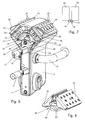
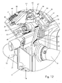
- the lock illustrated in the figures comprises a frame 1 which includes as main structural elements a cover box 2, an upper 3 and a lower side cover plate 4 for closing the lateral side of the box 2 and a base plate 5 arranged within the closed box 2.
- the base plate 5 has on one side an upstanding edge 6 and on its other side two upstanding edge portions 7, 8.
- the upper side cover plate 3 is fixed by means of screws 9 to the upper portion of the cover box 2 whilst the lower, substantially rectangular side cover plate is fixed by means of a screw 10 to the cover box 2.
- the cover box 2 is provided with two aligned openings 11 through which a cylinder 12 can be inserted in the lock, in particular a so-called Euro-cylinder corresponding to the standard DIN V18254/07.91.
- This cylinder 12 is fixed in the lock by means of a screw 13 passing through little holes made in the lower side cover plate 4 and in the upstanding edge 6 of the base plate 5.
- the cylinder 12 is a key actuated cylinder comprises a rotary driving bit which rotates around a central axis of the cylinder to actuate a dead bolt 14 of the lock. Since the mechanism for actuating a dead bolt 14 by means of a key actuated lock cylinder is well known, it has not been shown in the figures and will not be further described. Instead, reference is made to the description and the figures of EP-B-1 118 739 disclosing the key operated dead bolt actuating mechanism of the lock illustrated in the figures.
- the cover box 2 is further provided with two additional aligned openings 15 through which the door handles 16 can be mounted to the lock. Both handles 16 are mounted onto one single square handle shaft so that both handles always move simultaneously.
- the illustrated lock further comprises a lock bolt 17 which is operated by means of the handles 16 to move it between a locking (see Figure 11 ) and an unlocking position (see Figure 12 ).
- the bolt 17 is in particular a latch bolt which is slidably mounted on the frame 1 of the lock, more particularly within an opening 18 in the upstanding edge portion 7 and an opening 19 in the upstanding edge 6 of the base plate 5. The latch bolt 17 can thus move between a projecting position shown in Figure 11 and a retracted position shown in Figure 12 .
- a compression spring 20 is applied over the latch bolt 17 to urge this bolt to its projecting position.
- the rectangular handle shaft is inserted in a corresponding hole in a follower 21 (see Figure 21 ).
- This follower 21 is provided in its turn with a latch bolt lever 22 which follows the rotations of the handles 16 and which engages the latch bolt 17 against the action of a torsion spring 23 to retract this latch bolt.
- the torsion spring 23 serves to push the latch bolt lever 22 and thus the follower 21 and the handles 16 to their initial rest positions. Further details about the latch bolt actuating mechanism can be found in EP-B-1 118 739 , in particular also about a second turn lever which enables to retract the latch bolt by means of the key operated cylinder.
- the distance over which the latch bolt and the dead bolt of the lock illustrated in the figures projects out of the lock is adjustable due to the fact that the latch bolt and the dead bolt are provided with a projection 24 which is slidably mounted in the bolt and which can be displaced in the bolt through the intermediary of a set screw.
- a projection 24 which is slidably mounted in the bolt and which can be displaced in the bolt through the intermediary of a set screw.
- the lock according to the invention comprises a pushbutton operated locking mechanism for locking the lock bolt, in particular the latch bolt.
- the latch bolt When locked by this mechanism, the latch bolt can still be moved to its retracted position when closing the door or gate, i.e. when pushing it in against the latch bolt spring 20, or, when a second turn lever is provided, by means of a second turn of the key operated cylinder 12.
- the locking mechanism thus functions to prevent the lock bolt from being moved by the lock bolt actuating mechanism to its retracted or unlocking position.
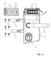
- the locking mechanism comprises a first series of pushbuttons 25 on the front side of the lock and a second series of pushbuttons 25 on the back side of the lock.
- the pushbuttons 25 are integrated in a keyboard 26 which comprises an upper lid portion 27 and a base plate 28 screwed against the upper lid portion to form a cavity for the pushbuttons.
- the pushbuttons 25 have head portions urged by means of springs 29 through openings out of the upper lid portion 27 and stem portions which extend through openings through the base plate when the pushbuttons 25 are pushed in.
- the keyboard 26 also comprises a reset button 30.
- the keyboards 26 have a circumferential groove by means of which they can be slid each in an upper, rectangular opening in the cover box 2.
- a retainer element 32 which is fixed by a screw 31 to the lateral side of the lock, the keyboards 26 are prevented from being removed from the lock.
- the keyboards 26 can however be easily removed from the lock after having removed the retainer element 32.
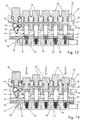
- the locking mechanism further comprises two series of tumbler members 33, namely a first series of tumbler members which are movable between normal and depressed stable positions by means of the first series of pushbuttons 25 and a second series of tumbler members which are movable between normal and depressed stable positions by means of the second series of pushbuttons 25.
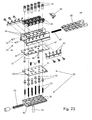
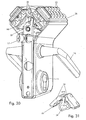
- the tumbler members 33 are arranged, on the one hand, in holes 34 in a frame component 35 which is fixed by means of pegs 36 and screws 37 to the cover box 2 and, on the other hand, in holes 38 in two check slides 39 which are slidably mounted on the frame component 35 (see Figures 20 and 23 ). Depending on the positions of the tumbler members 33, the check slides 39 are either blocked or released with respect to the frame component 35.
- the tumbler members 33 each consist of a first tumbler element, composed of a base body 40 and a code body 41, and a second tumbler element 42.
- the base bodies 40 are slidably mounted in the holes 34 in the frame component 35.
- the base bodies 40 each have two recesses on one lateral side which can be engaged by a spring detent 43, more particularly by leaf springs fixed against both sides of the frame component 35 and extending through slits therein into the holes 34.
- spring detents comprising compression springs.
- the code bodies 41 are of two different lengths and are removably fixed to the base bodies 40 to extend through axial holes provided therein.
- the code bodies 41 can for example be snapped in the holes in the base bodies 40.
- the code bodies 41 are in the form of screws which can be screwed easily and reliably into the base bodies 40.
- a reset slide 44 is provided in each of the frame components 35.
- This reset slide 44 is biased by means of a spring 45 to its rest position and can be moved by depressing of the reset button 30, through the intermediary of a lever 46, against the spring bias.
- the reset slide 44 is provided with oblique cam surfaces (forming a kind of saw tooth) engaging an oblique bottom surface of the base bodies 40 to lift the tumbler elements 40, 41 to their normal positions when the reset slide 44 is moved against the spring bias.
- the frame component 35 comprises a bottom plate 47 which is fixed to the main part of the frame component by means of screws 48.
- the bottom plate 47 is provided with openings 49 which are part of the holes 34 in the frame component 35 and which are arranged to receive and guide the lower extremities of the code bodies 41.
- the check slides 39 are guided on the frame components 35 along the bottom plates 47 and comprise a main body part 50, forming part of the holes 38 for slidably receiving the second tumbler elements 42, and a top plate 51 fixed by means of screws 52 to the main body part 50.
- the top plate 51 shows openings 53 which are part of the holes 38 in the frame component 35 and which are arranged to receive and guide the second tumbler elements 42.
- These second tumbler elements 42 are more particularly biased by means of springs 54 to project out of the openings 53 until a flange on the second tumbler elements 42 engages the top plate 51.
- the check slides 39 are biased by means of springs 55 to their first or rest position. In that position the openings 49 in the bottom plate 47 (forming part of the holes 34 in the frame component 35) and the openings 53 in the top plate 53 (forming part of the holes 38 in the check slides 39) are situated opposite one another so that the second tumbler elements 42 are biased by means of the springs 54 against the first tumbler elements, more particularly against the code bodies 41 thereof.
- At least one of the first tumbler elements 40, 41 is a code tumbler element, which comprises a "short" code body 40 so that the corresponding second tumbler element 42 extends into the hole 34 in the frame component 35 to block the check slide 38 when all the tumbler members have been reset.
- the first tumbler elements 40, 41 may also comprise (and will normally comprise) one or more block tumbler elements, which comprise a "long" code body 40 having such a length that, in the reset position of the tumbler members, they push the corresponding second tumbler elements 42 into the holes 38 in the check slides 39, without projecting themselves into these holes 38.
- the block tumbler elements therefore do not block the reset slides when they are not depressed but they do block the reset slides when being depressed.
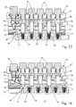
- FIG 13 The blocked position of the check slide 39 when all of the tumbler members 33 have been reset is illustrated in Figure 13 .
- the check slide 39 can be released by depressing only the code tumbler elements by means of the respective push buttons 25. Since the pushbuttons 25 return immediately back to their rest position when being released, the number combination required to release the check slide cannot be seen from the outside when the check slide has been released (see Figure 15 ).
- Figure 17 when one of the block tumbler elements is wrongly depressed, it extends into the corresponding hole in the check slide and blocks the check slide. In this case, the tumbler members have to be reset all by means of the reset button 30 and the correct number combination has to be put in again.
- Figure 16 illustrates the sliding movement of the released check slide 39 from its first normal position, against the bias of the spring 55, to its second position. It also illustrates that during this movement all of the tumbler members 33 are automatically reset by the reset slide 44, i.e. without having to operate the reset button 30. Once the door or gate has been opened and is closed again, it is thus automatically locked.
- the automatic reset of the tumbler members 33 is achieved by means of the peg 56 which is fixed, as shown in Figure 23 , in a hole in the check slide 39. This peg 56 extends through a slit 57 in the frame component 35 (more particularly in the bottom plate 47 thereof) and through a slit 58 in the reset slide 44.
- the peg 56 in the normal rest position of the check slide 39, the peg 56 extends in the left end of the slit 57 and in the right end of the slit 58.
- the tumbler members 33 can thus be reset by moving the check slide 39, and at the same time the reset slide 44, to the right (when the check slide has been released by means of the right number combination) or by moving only the reset slide 44, by means of the reset button 30, to the right (which is possible even when a wrong number combination has been used so that the check slide is blocked).
- the lock according to the invention comprises a selector 59, illustrated in Figures 5 to 12 and 21 , which can be blocked or released by the first and second check slides 39 and which couples these check slides to the lock bolt mechanism, i.e. either to the bolt itself or to the lock bolt actuating mechanism.
- the selector 59 is coupled to the latch bolt actuating mechanism so that when the tumbler members are automatically reset after having opened the door or gate (and the check slide is thus blocked again), the door or gate can still simply be closed without having to put in the right number combination again.
- the latch bolt lever 22 does not only act upon the projection 24 on the latch bolt 17 but extends further to engage a lever 60 which is pivoted about a pivot 61 fixed to the frame (see Figure 21 ).
- the latch bolt lever 22 engages the lever 60 at a first distance from the pivot 61.
- the lever 60 itself engages the selector 59 at a second distance from the pivot 61 which is smaller than the first distance. In this way, the displacement of the selector 59 is reduced so that a smaller force has to be exerted onto the latch bolt lever 22 and so that especially the locking mechanism can be made more compact as will appear hereafter (the holes in the check slides 39 can be made closer to one another due to the smaller displacement of the check slides).
- an additional lever can be provided therefor on the latch bolt actuating mechanism.
- the selector 59 is slidably mounted on the frame, more particularly onto a shaft 62 having one end fixed to the cover box 2 and the other end fixed to the upstanding edge 6 of the base plate 5.
- the selector 59 comprises a main body part 63 and a switch element 64 pivotally mounted about a pivot 65 on the main body part 63 of the selector 59.
- the switch element 64 is a triangular element, one side of which is in engagement with the first check slide 39 and another side of which is in engagement with the second check slide 39.
- the switch element 64 switches automatically to the check slide which is released.
- the sides of the switch element form cam surfaces which engage cams formed by the (edges of the) check slides so that the switch element automatically pivots towards the released check slide when the selector is pushed against the check slides. It is also possible to round the edges of check slides so that these rounded edges form cam surfaces whilst the switch element forms cams sliding along these cam surfaces.
- the triangular switch element 64 illustrated in the figures is in fact a lever having a first lever arm situated on one side of the pivot 65 and engaging the first check slide and a second lever arm situated on the opposite side of the pivot 65 and engaging the second check slide 39.
- the selector 59 comprises a switch element 64 which is the main body part of the selector 59 and which cannot only slide over the shaft 62 but which can also pivot about this shaft 62.
- the selector 59 has a lever arm 66 which engages a bevelled edge 67 of the check slides 39 so that it automatically pivots towards the check slide 39 which is released.
- the lever 60 is now replaced by a lever 60 which pivots about a horizontal instead of about a vertical pivot 61 and has a curved side engaging the selector so as to reduce the frictional forces.
- the switch element could be modified so that it would no longer automatically switch to the released check slide but so that the person who wants to unlock the lock has to push in for example a pushbutton which moves the selector to the check slide which can be released from the side of the lock where the person is present. Since such an embodiment is more complex and less user friendly, it is less preferred.
- a first advantage of the lock illustrated in the drawings is that the number combination may be different on both sides of the lock and can easily be changed, as illustrated in Figures 2 to 4 , by simply removing the respective keyboard 26 and by replacing the "shorter" code tumbler elements by "longer" block tumbler elements or vice versa.
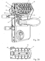
- a further advantage is that one of the keyboards 26 may even be replaced by a keyboard with only one large pushbutton 68 so that the lock can very easily be unlocked from one side of the door or gate.
- a keyboard with only one large pushbutton 68 Such a possibility is illustrated in Figures 24 and 25 and is very suitable if the door or gate allows no or difficult access to the other side of the lock.
- the keyboard with the large pushbutton can be sold, as a set, with the lock according to the invention.
- An advantage of the two same locking mechanisms on both sides of the lock is that the keyboard with the large pushbutton can be used on either side of the lock so that a same lock can be used both for left and for right turning doors.
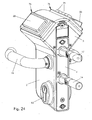
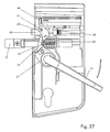
- the security slide 69 is also linked to the lock handle 16 through the follower 21, latch bolt lever 22, lever 60 and selector 59, so that, when the lock handle 16 is depressed, the security slide 69 will be displaced from a first position, illustrated in Figs. 32 , 34 and 35 to a second position, illustrated in Figs. 33 , 36 and 37 .
- a small distance is provided between the selector 59 and the check slides 39.
- the security slide 69 comprises a plate-like portion 70 which is interposed between said first series of pushbuttons 25 and said first series of tumbler members 33, and which comprises a first series of holes 71 corresponding to the first series of pushbuttons 25. In the first position illustrated in Figs.
- the holes 71 are aligned between the pushbuttons 25 and the tumbler members 33, allowing said pushbuttons 25 to engage said tumbler members 33 when depressed.
- the security slide 69 is displaced to the second position illustrated in Figs. 33 , 36 and 37 , the holes 71 are no longer aligned, and the plate 70 locks the pushbuttons 25 in their normal position, out of engagement with the tumbler members 33.
- the pushbuttons 25 can therefore only be depressed when the lock handle 16 is released.
- the security slide 69 is normally held in the first position by the selector 59, more particularly under the bias of a relatively strong additional coil spring 73, and biased towards the second position by a less strong spiral spring 72. In this way, if the selector 59 moves slightly due to actuation of the lock handle 16 as illustrated in Fig. 36 , the additional coil spring 73 is compressed and the coil spring 72 urges the security slide 69 to its second position.
- Alternatives to this arrangement such as using a leaf spring instead of spiral spring 72 or a different coupling with the lock bolt actuating mechanism are within the reach of the skilled person.
- a further security slide 69 is preferably provided so that there are two security slides 69, one for each side of the lock.
- the two security slides 69 are preferably connected to one another so that the two series of pushbuttons are simultaneously blocked when operating the lock bolt actuating mechanism.
- the second security slide 69 would of course be unnecessary.
Landscapes
- Lock And Its Accessories (AREA)
- Push-Button Switches (AREA)
- Preventing Unauthorised Actuation Of Valves (AREA)
- Electrophonic Musical Instruments (AREA)
- Input Circuits Of Receivers And Coupling Of Receivers And Audio Equipment (AREA)
- Bidet-Like Cleaning Device And Other Flush Toilet Accessories (AREA)
Claims (15)
- Ein Druckknopf-Kombinationsschloss, das Folgendes umfasst:- einen Rahmen (1);- einen Schlossriegelmechanismus, der Folgendes umfasst:- einen Schlossriegel (17), beweglich zwischen einer Verriegelungsund einer Entriegelungsposition auf dem Rahmen (1) montiert; und- einen Betätigungsmechanismus (21, 22) des Schlossriegels, angeordnet, um den Schlossriegel (17) zwischen der Verriegelungs- und der Entriegelungsposition zu bewegen und bedienbar von einer ersten und einer zweiten Seite des Schlosses; und- einen Verriegelungsmechanismus zum Verriegeln des Schlossriegelmechanismus, um zu verhindern, dass der Schlossriegel (17) durch den Betätigungsmechanismus (21, 22) des Schlossriegels in die Entriegelungsposition bewegt werden kann, wobei dieser Verriegelungsmechanismus Folgendes umfasst:- eine erste Reihe von Druckknöpfen (25) auf der ersten Seite des Schlosses und eine zweite Reihe von Druckknöpfen (25) auf der zweiten Seite des Schlosses;- eine erste Reihe von Kippschaltern (33), beweglich zwischen normalen und eingedrückten stabilen Positionen durch respektive Druckknöpfe (25) der erwähnten ersten Druckknopfreihe; und- einen ersten Kontrollschieber (39), beweglich zwischen einer ersten und einer zweiten Position auf dem Rahmen (1) montiert und zusammenwirkend mit der ersten Reihe von Kippschaltern (33), um, in seiner ersten Position, blockiert zu sein, oder dadurch freigegeben zu werden, um in seine zweite Position bewegt werden zu können;dadurch gekennzeichnet, dass
der Verriegelungsmechanismus ferner Folgendes umfasst:- eine zweite Reihe von Kippschaltern (33), beweglich zwischen normalen und eingedrückten stabilen Positionen durch respektive Druckknöpfe (25) der erwähnten zweiten Druckknopfreihe;- einen zweiten Kontrollschieber (39), beweglich zwischen einer ersten und einer zweiten Position auf dem Rahmen (1) montiert und zusammenwirkend mit der zweiten Reihe von Kippschaltern (33), um, in seiner ersten Position, blockiert zu sein, oder dadurch freigegeben zu werden, um in seine zweite Position bewegt werden zu können; und- einen Wahlschalter (59), welcher beweglich auf dem Rahmen (1) montiert ist und durch den ersten und zweiten Kontrollschieber (39) blockiert oder freigegeben wird, wobei der Wahlschalter (59) den ersten und/oder den zweiten Kontrollschieber (39) mit dem Schlossriegelmechanismus (17, 21, 22) verbindet, sodass der Wahlschalter (59), zumindest wenn der erste und der zweite Kontrollschieber blockiert sind, blockiert ist und den Schlossriegelmechanismus verriegelt, und wobei der Wahlschalter (59) angeordnet ist, um durch entweder den ersten oder den zweiten Kontrollschieber (39) freigegeben zu werden, sodass der Schlossriegelmechanismus (17, 21, 22) durch Freigabe des ersten oder respektive des zweiten Kontrollschiebers (39) entriegelt werden kann. - Ein Schloss nach Anspruch 1, dadurch gekennzeichnet, dass der Wahlschalter (59) ein Schalterelement (64) umfasst,- das sowohl in den ersten als auch den zweiten Kontrollschieber (39) einklinkt, um den Schlossriegelmechanismus zu verriegeln, wenn der erste und der zweite Kontrollschieber (39) blockiert sind,- das zum ersten Kontrollschieber (39) schaltet, sodass der Wahlschalter (59) freigegeben und der Schlossriegelmechanismus dadurch entriegelt wird, wenn der erste Kontrollschieber (39) freigegeben wird, während der zweite Kontrollschieber (39) blockiert bleibt, und- das zum zweiten Kontrollschieber (39) schaltet, sodass der Wahlschalter freigegeben und der Schlossriegelmechanismus dadurch entriegelt wird, wenn der zweite Kontrollschieber (39) freigegeben wird und der erste Kontrollschieber (39) blockiert bleibt.
- Ein Schloss nach Anspruch 2, dadurch gekennzeichnet, dass das Schalterelement (64) schwenkbar um eine Achse (65) montiert ist und dass das Schalterelement (64) und der erste und der zweite Kontrollschieber (39) miteinander zusammenwirkende Nocken und Nockenlaufbahnen umfassen, um das Schalterelement (64) zu schwenken, um bei Bedienung des Betätigungsmechanismus des Schlossriegels zum ersten oder zum zweiten Kontrollschieber (39) zu schalten, wenn der erste oder respektive der zweite Kontrollschieber (39) freigegeben und der andere Kontrollschieber (39) blockiert sind.
- Ein Schloss nach Anspruch 2 oder 3, dadurch gekennzeichnet, dass das Schalterelement (64) einen Schalthebel umfasst, welcher schwenkbar um eine Achse (65) montiert ist und einen ersten Hebelarm auf einer Seite der Achse (65) hat, der in den ersten Kontrollschieber (39) einklinkt, und einen zweiten Hebelarm auf einer gegenüberliegenden Seite der Achse hat, der in den zweiten Kontrollschieber (39) einklinkt.
- Ein Schloss nach irgendeinem der Ansprüche 1 bis 4, gekennzeichnet, dass es ferner einen Sicherheitsmechanismus umfasst, der zumindest einen ersten Sicherheitsschieber (69) einschließt, welcher zwischen der erwähnten ersten Serie von Druckknöpfen (25) und der erwähnten ersten Reihe von Kippschaltern (33) eingeschaltet ist und beweglich ist zwischen einer ersten Position, in der er zulässt, dass die Kippschalter (33) der ersten Reihe durch die respektiven Druckknöpfe (25) der ersten Druckknopfreihe von ihren normalen in ihre eingedrückten stabilen Positionen bewegt werden, und einer zweiten Position, in der er verhindert, dass die Kippschalter (33) der ersten Reihe durch die respektiven Druckknöpfe (25) der ersten Druckknopfreihe von ihren normalen in ihre eingedrückten stabilen Positionen bewegt werden, wobei der Sicherheitsschieber (69) mit dem Schlossriegelmechanismus (17, 21, 22) verbunden ist, sodass er in die erwähnte zweite Position bewegt wird, wenn der erwähnte Schlossriegelmechanismus (17, 21, 22) betätigt wird, um den Schlossriegel (17) in seine Entriegelungsposition zu bewegen.
- Ein Schloss nach Anspruch 5, dadurch gekennzeichnet, dass der erwähnte Sicherheitsmechanismus einen zweiten Sicherheitsschieber (69) umfasst, welcher zwischen der erwähnten zweiten Serie von Druckknöpfen (25) und der erwähnten zweiten Reihe von Kippschaltern (33) eingeschaltet ist und beweglich ist zwischen einer ersten Position, in der er zulässt, dass die Kippschalter (33) der zweiten Reihe durch die respektiven Druckknöpfe (25) der zweiten Druckknopfreihe von ihren normalen in ihre eingedrückten stabilen Positionen bewegt werden, und einer zweiten Position, in der er verhindert, dass die Kippschalter (33) der zweiten Reihe durch die respektiven Druckknöpfe (25) der zweiten Druckknopfreihe von ihren normalen in ihre eingedrückten stabilen Positionen bewegt werden, wobei der zweite Sicherheitsschieber (69) mit dem Schlossriegelmechanismus (17, 21, 22) verbunden ist, sodass er in die erwähnte zweite Position bewegt wird, wenn der erwähnte Schlossriegelmechanismus (17, 21, 22) betätigt wird, um den Schlossriegel (17) in seine Entriegelungsposition zu bewegen, und der zweite Sicherheitsschieber (69) vorzugsweise mit dem ersten Sicherheitsschieber (69) verbunden ist.
- Ein Schloss nach irgendeinem der Ansprüche 1 bis 6, dadurch gekennzeichnet, dass der Schlossriegel ein Fallriegel (17) ist, welcher mittels einer Fallriegelfeder (20) aus dem Rahmen (1) des Schlosses vorgespannt wird, und dass der Wahlschalter (59) den ersten und/oder den zweiten Kontrollschieber (39) mit dem Betätigungsmechanismus (21, 22) des Schlossriegels verbindet, sodass der Fallriegel (17) gegen die Federvorspannung eingedrückt werden kann, auch wenn sowohl der erste als auch der zweite Kontrollschieber (39) blockiert sind.
- Ein Schloss nach Anspruch 7, dadurch gekennzeichnet, dass es ferner einen stehenden Riegel (14) und einen schlüsselbedienten Betätigungsmechanismus (12) des stehenden Riegels umfasst.
- Ein Schloss nach irgendeinem der Ansprüche 1 bis 8, dadurch gekennzeichnet, dass der Verriegelungsmechanismus ferner einen ersten Rückstellschieber (44) zum Rückstellen aller Kippschalter (33) der ersten Reihe in ihre normalen Positionen und einen zweiten Rückstellschieber (44) zum Rückstellen aller Kippschalter (33) der zweiten Reihe in ihre normalen Positionen umfasst, wobei sowohl der erste, als auch der zweite Kontrollschieber (39) blockiert sind, wenn die Kippschalter (33) der ersten und der zweiten Reihe in ihren normalen Positionen sind.
- Ein Schloss nach Anspruch 9, dadurch gekennzeichnet, dass es ein erstes Kuppelelement (56), eingeschaltet zwischen dem ersten Kontrollschieber (39) und dem ersten Rückstellschieber (44), und ein zweites Kuppelelement (56), eingeschaltet zwischen dem zweiten Kontrollschieber (39) und dem zweiten Rückstellschieber (44), umfasst, um den ersten und zweiten Rückstellschieber (44) bei Betätigung des ersten und respektive des zweiten Kontrollschiebers (39) zu betätigen.
- Ein Schloss nach irgendeinem der Ansprüche 1 bis 10, dadurch gekennzeichnet, dass die zweite Reihe von Druckknöpfen (25) durch einen einzigen Druckknopf (68) ersetzt ist, der auf eine Anzahl der Kippschalter (33) der zweiten Reihe wirkt, um diese in ihre eingedrückte Position zu bewegen, wenn der Druckknopf (68) eingedrückt wird, wobei die Kippschalter (33) der zweiten Reihe so ausgewählt werden, dass nur der oder die Kippschalter (33), auf den/die der einzige Druckknopf (68) wirkt, eingedrückt werden muss/müssen, um den zweiten Kontrollschieber (39) freizugeben.
- Ein Schloss nach irgendeinem der Ansprüche 1 bis 11, dadurch gekennzeichnet, dass der erwähnte Betätigungsmechanismus (21, 22) des Schlossriegels eine Manschette umfasst, die schwenkbar auf dem Rahmen (1) montiert ist und angeordnet ist, um einen Griffstift aufzunehmen, wobei die Manschette (21) mit einem Hebel (22) ausgestattet ist, welcher mit dem Wahlschalter (59) verbunden ist, um die Manschette (21) zu blockieren, wenn der Wahlschalter (59) blockiert ist, und um die Manschette (21) freizugeben, damit der Schlossriegel (17) mittels der Manschette (21) in seine Entriegelungsposition bewegt werden kann, wenn der Wahlschalter (59) freigegeben ist.
- Ein Schloss nach Anspruch 12, dadurch gekennzeichnet, dass der Hebel (22) auf der Manschette (21) mittels eines weiteren Hebels (60), welcher schwenkbar um eine Achse (61) auf dem Rahmen (1) montiert ist, mit dem Wahlschalter (59) verbunden ist, wobei der Hebel (22) auf der Manschette (21) in einem ersten Abstand von der erwähnten Achse (61) in den weiteren Hebel (60) einklinkt und der weitere Hebel (60) in einem zweiten Abstand von der erwähnten Achse (61) in den Wahlschalter (59) einklinkt.
- Ein Schloss nach irgendeinem der Ansprüche 1 bis 12, dadurch gekennzeichnet, dass die Kippschalter (33) jeweils ein erstes (40, 41) und ein zweites Kippelement (42) umfassen, dass der Rahmen (1) mit Löchern (34) versehen ist, angeordnet, um die ersten Kippelemente (40, 41) aufzunehmen, und der erste und der zweite Kontrollschieber (39) mit weiteren Löchern (38) versehen sind, angeordnet, um die zweiten Kippelemente (42) aufzunehmen, und dadurch, dass sich die erwähnten weiteren Löcher (38), wenn sich der erste und der zweite Kontrollschieber (39) in ihrer ersten Position befinden, gegenüber den erwähnten Löchern (34) befinden, die ersten Kippelemente (40, 41) mittels des respektiven Druckknopfs (25) in den erwähnten Löchern (34) zwischen einer ersten stabilen Position, in der der Kippschalter (33) in seiner normalen Position ist, und einer zweiten stabilen Position axial beweglich sind, in der der Kippschalter (33) in seiner eingedrückten Position ist, und die zweiten Kippelemente (42) in den erwähnten weiteren Löchern (38) axial beweglich sind und mittels Federn (54) gegen das entsprechende erste Kippelement (40, 41) vorgespannt werden, die ersten Kippelemente (40, 41) der ersten Reihe und die ersten Kippelemente (40, 41) der zweiten Reihe von Kippschaltern (33) jeweils ein oder mehrere Kode-Kippelemente (40, 41) mit einer solchen Länge umfassen, dass, wenn sie sich in der erwähnten ersten Position befinden, die entsprechenden zweiten Kippelemente (42), welche in die Kode-Kippelemente einklinken, in eines der erwähnten Löcher (34) hineinragen, um den ersten und respektive den zweiten Kontrollschieber (39) zu blockieren, und wenn die Kode-Kippelemente in der erwähnten zweiten Position sind, sie die entsprechenden zweiten Kippelemente (42) in die erwähnten weiteren Löcher (38) drücken, ohne selbst dort hinein zu ragen, wobei eventuell verbleibende erste Kippelemente (40, 41) Block-Kippelemente mit einer solchen Länge sind, dass sie, wenn sie sich in der erwähnten ersten Position befinden, die entsprechenden zweiten Kippelemente (42), welche in die Block-Kippelemente einklinken, in die erwähnten weiteren Löcher (38) drücken, ohne selbst in diese Löcher zu ragen, und wenn sich die Block-Kippelemente (40, 41) in der erwähnten zweiten Position befinden, diese in die erwähnten weiteren Löcher (38) ragen, wodurch sie den respektiven Kontrollschieber (39) blockieren.
- Ein Schloss nach Anspruch 14, dadurch gekennzeichnet, dass die ersten Kippelemente (40, 41) jeweils ein Basisteil (40) und ein Kodeteil (41) umfassen, wobei die Basisteile (40) ein axiales Durchgangsloch haben und beweglich in einem der erwähnten Löcher (34) montiert sind, und die Kodeteile (41) freigebbar am respektiven Basisteil (40) befestigt, vorzugsweise angeschraubt sind, um sich durch das erwähnte Durchgangsloch auszustrecken und in das entsprechende zweite Kippelement (42) einzuklinken.
Priority Applications (3)
| Application Number | Priority Date | Filing Date | Title |
|---|---|---|---|
| EP06830611A EP1984591B8 (de) | 2006-01-31 | 2006-12-13 | Kombinationsschloss für druckknopf |
| EP20100160120 EP2202370B1 (de) | 2006-01-31 | 2006-12-13 | Drucktaste-Kombinationsschloss |
| PL06830611T PL1984591T3 (pl) | 2006-01-31 | 2006-12-13 | Przyciskowy zamek szyfrowy |
Applications Claiming Priority (3)
| Application Number | Priority Date | Filing Date | Title |
|---|---|---|---|
| EP20060101116 EP1813743A1 (de) | 2006-01-31 | 2006-01-31 | Drucktaste-Kombinationsschloss |
| EP06830611A EP1984591B8 (de) | 2006-01-31 | 2006-12-13 | Kombinationsschloss für druckknopf |
| PCT/EP2006/069691 WO2007087932A2 (en) | 2006-01-31 | 2006-12-13 | Pushbutton combination lock |
Related Child Applications (1)
| Application Number | Title | Priority Date | Filing Date |
|---|---|---|---|
| EP10160120.1 Division-Into | 2010-04-16 |
Publications (3)
| Publication Number | Publication Date |
|---|---|
| EP1984591A2 EP1984591A2 (de) | 2008-10-29 |
| EP1984591B1 true EP1984591B1 (de) | 2010-04-21 |
| EP1984591B8 EP1984591B8 (de) | 2010-06-16 |
Family
ID=36643334
Family Applications (3)
| Application Number | Title | Priority Date | Filing Date |
|---|---|---|---|
| EP20060101116 Withdrawn EP1813743A1 (de) | 2006-01-31 | 2006-01-31 | Drucktaste-Kombinationsschloss |
| EP06830611A Active EP1984591B8 (de) | 2006-01-31 | 2006-12-13 | Kombinationsschloss für druckknopf |
| EP20100160120 Active EP2202370B1 (de) | 2006-01-31 | 2006-12-13 | Drucktaste-Kombinationsschloss |
Family Applications Before (1)
| Application Number | Title | Priority Date | Filing Date |
|---|---|---|---|
| EP20060101116 Withdrawn EP1813743A1 (de) | 2006-01-31 | 2006-01-31 | Drucktaste-Kombinationsschloss |
Family Applications After (1)
| Application Number | Title | Priority Date | Filing Date |
|---|---|---|---|
| EP20100160120 Active EP2202370B1 (de) | 2006-01-31 | 2006-12-13 | Drucktaste-Kombinationsschloss |
Country Status (11)
| Country | Link |
|---|---|
| US (1) | US8276413B2 (de) |
| EP (3) | EP1813743A1 (de) |
| AT (2) | ATE465313T1 (de) |
| AU (1) | AU2006337448A1 (de) |
| CA (1) | CA2639887A1 (de) |
| DE (1) | DE602006013885D1 (de) |
| DK (1) | DK1984591T3 (de) |
| ES (1) | ES2344473T3 (de) |
| PL (1) | PL1984591T3 (de) |
| PT (1) | PT1984591E (de) |
| WO (1) | WO2007087932A2 (de) |
Cited By (1)
| Publication number | Priority date | Publication date | Assignee | Title |
|---|---|---|---|---|
| EP2886755A1 (de) | 2013-12-20 | 2015-06-24 | Joseph Talpe | Druckknopf-Kombinationsschloss |
Families Citing this family (5)
| Publication number | Priority date | Publication date | Assignee | Title |
|---|---|---|---|---|
| EP2510170A4 (de) * | 2009-12-07 | 2017-11-29 | Master Lock Company LLC | Blockieranordnungen für mechanische druckknöpfe |
| JP4812888B1 (ja) * | 2010-05-31 | 2011-11-09 | 株式会社長沢製作所 | ボタン錠 |
| US11746566B2 (en) * | 2020-05-19 | 2023-09-05 | Jacob Adamosky | Ladder latch |
| GB2613770A (en) * | 2021-10-23 | 2023-06-21 | Supra Uk Ltd | A lock |
| EP4596814A1 (de) * | 2024-01-30 | 2025-08-06 | Locinox | Kombinationsschloss zum verriegeln eines verschlusselements |
Family Cites Families (19)
| Publication number | Priority date | Publication date | Assignee | Title |
|---|---|---|---|---|
| GB918696A (de) | ||||
| US1500657A (en) * | 1922-03-27 | 1924-07-08 | Otto H Stolberg | Permutation lock |
| DE512619C (de) * | 1927-11-08 | 1930-11-21 | Francis Carteret Bishop | Kombinationsschloss mit zwei Gruppen zweiteiliger Druckknopfzuhaltungen |
| FR799690A (fr) * | 1935-03-21 | 1936-06-17 | Serrure sans clef à combinaison | |
| US2109264A (en) * | 1937-08-18 | 1938-02-22 | Julius November | Lock |
| US2997872A (en) * | 1958-10-02 | 1961-08-29 | Brooks Carroll | Lock |
| US3009346A (en) * | 1958-10-15 | 1961-11-21 | Yale & Towne Mfg Co | Keyless lock |
| US3099150A (en) * | 1961-12-19 | 1963-07-30 | Yale & Towne Mfg Co | Combination push button lock |
| US3187528A (en) * | 1962-07-13 | 1965-06-08 | Yale & Towne Inc | Anti-tamper keyless lock |
| JPS5771968A (en) * | 1980-10-21 | 1982-05-06 | Nagasawa Seisakusho | Button lock |
| GB2176233A (en) * | 1985-06-11 | 1986-12-17 | Nan Tien Su | Push-button combination lock |
| US6145355A (en) | 1998-01-22 | 2000-11-14 | Interlogix, Inc. | Pushbutton lock |
| GB2343482B (en) * | 1998-11-04 | 2000-09-27 | Wang Song Ming | Numeral lock with resettable feature |
| DE60019254T2 (de) | 2000-01-21 | 2006-02-16 | Talpe Jun., Joseph | Schloss |
| JP3764863B2 (ja) * | 2001-11-06 | 2006-04-12 | 株式会社シュア製作所 | 押しボタン施錠装置 |
| CN2616614Y (zh) * | 2003-04-28 | 2004-05-19 | 梁照源 | 按键式机械密码锁的锁体 |
| US7043948B1 (en) * | 2004-11-23 | 2006-05-16 | Song-Ming Wang | Resettable combination lock |
| US7318331B2 (en) * | 2005-12-28 | 2008-01-15 | Jin Tay Industries Co., Ltd. | Combination lock having a knob rotatably mounted therein to activate/deactivate the locking mechanism of the combination lock |
| US20080115546A1 (en) * | 2006-11-22 | 2008-05-22 | Jeffery Hu | Pushbutton lock |
-
2006
- 2006-01-31 EP EP20060101116 patent/EP1813743A1/de not_active Withdrawn
- 2006-12-13 ES ES06830611T patent/ES2344473T3/es active Active
- 2006-12-13 AT AT06830611T patent/ATE465313T1/de active
- 2006-12-13 AU AU2006337448A patent/AU2006337448A1/en not_active Abandoned
- 2006-12-13 WO PCT/EP2006/069691 patent/WO2007087932A2/en not_active Ceased
- 2006-12-13 EP EP06830611A patent/EP1984591B8/de active Active
- 2006-12-13 EP EP20100160120 patent/EP2202370B1/de active Active
- 2006-12-13 US US12/162,401 patent/US8276413B2/en active Active
- 2006-12-13 PL PL06830611T patent/PL1984591T3/pl unknown
- 2006-12-13 DE DE200660013885 patent/DE602006013885D1/de active Active
- 2006-12-13 CA CA 2639887 patent/CA2639887A1/en not_active Abandoned
- 2006-12-13 DK DK06830611T patent/DK1984591T3/da active
- 2006-12-13 AT AT10160120T patent/ATE533908T1/de active
- 2006-12-13 PT PT06830611T patent/PT1984591E/pt unknown
Cited By (2)
| Publication number | Priority date | Publication date | Assignee | Title |
|---|---|---|---|---|
| EP2886755A1 (de) | 2013-12-20 | 2015-06-24 | Joseph Talpe | Druckknopf-Kombinationsschloss |
| US9790710B2 (en) | 2013-12-20 | 2017-10-17 | Joseph Talpe | Pushbutton combination lock |
Also Published As
| Publication number | Publication date |
|---|---|
| EP2202370B1 (de) | 2011-11-16 |
| EP1984591B8 (de) | 2010-06-16 |
| US8276413B2 (en) | 2012-10-02 |
| WO2007087932A2 (en) | 2007-08-09 |
| ATE533908T1 (de) | 2011-12-15 |
| DE602006013885D1 (de) | 2010-06-02 |
| EP1813743A1 (de) | 2007-08-01 |
| EP1984591A2 (de) | 2008-10-29 |
| ATE465313T1 (de) | 2010-05-15 |
| WO2007087932A3 (en) | 2007-11-08 |
| CA2639887A1 (en) | 2007-08-09 |
| DK1984591T3 (da) | 2010-08-09 |
| PT1984591E (pt) | 2010-07-15 |
| US20090013737A1 (en) | 2009-01-15 |
| PL1984591T3 (pl) | 2010-09-30 |
| EP2202370A1 (de) | 2010-06-30 |
| ES2344473T3 (es) | 2010-08-27 |
| AU2006337448A1 (en) | 2007-08-09 |
Similar Documents
| Publication | Publication Date | Title |
|---|---|---|
| US6216500B1 (en) | Device for unlocking tubular-type door lock in conjunction with indoor handle | |
| US7963134B2 (en) | Deadbolt lock | |
| US4936894A (en) | Pushbutton lock | |
| US6026665A (en) | Door lock combination chambers | |
| JPS6254951B2 (de) | ||
| CA2475429A1 (en) | Latching devices for gates and doors | |
| US9790710B2 (en) | Pushbutton combination lock | |
| US4602491A (en) | Combination lock | |
| GB2413154A (en) | Latch assemblies | |
| US4827743A (en) | Combination lock | |
| EP1984591B1 (de) | Kombinationsschloss für druckknopf | |
| JPH0726496B2 (ja) | 安全装置の内設されたドア・ロック | |
| CN113236044A (zh) | 一种门锁 | |
| US9890560B2 (en) | Locking apparatus | |
| CN109642436B (zh) | 一种锁 | |
| US9279274B2 (en) | Lock | |
| EP3508670B1 (de) | Verriegelungsanordnung | |
| US7010944B1 (en) | Padlock having restoring mechanism | |
| RU2475614C2 (ru) | Врезной замок с зубчатым элементом разблокирования запорного ригеля | |
| GB2401645A (en) | Mechanical combination lock | |
| JPH0734114Y2 (ja) | キーレス施錠装置 | |
| AU2009100523A4 (en) | Improvements in locks | |
| CS261488B1 (cs) | Bezklíčový mechanický kódjvatelný ovladač zámků | |
| WO2004065732A1 (en) | A lock and key | |
| CZ15633U1 (cs) | Mechanizmus kódované kíÍKv s postupným ovládáním a aretací stavítek |
Legal Events
| Date | Code | Title | Description |
|---|---|---|---|
| PUAI | Public reference made under article 153(3) epc to a published international application that has entered the european phase |
Free format text: ORIGINAL CODE: 0009012 |
|
| 17P | Request for examination filed |
Effective date: 20080828 |
|
| AK | Designated contracting states |
Kind code of ref document: A2 Designated state(s): AT BE BG CH CY CZ DE DK EE ES FI FR GB GR HU IE IS IT LI LT LU LV MC NL PL PT RO SE SI SK TR |
|
| GRAP | Despatch of communication of intention to grant a patent |
Free format text: ORIGINAL CODE: EPIDOSNIGR1 |
|
| GRAS | Grant fee paid |
Free format text: ORIGINAL CODE: EPIDOSNIGR3 |
|
| GRAA | (expected) grant |
Free format text: ORIGINAL CODE: 0009210 |
|
| AK | Designated contracting states |
Kind code of ref document: B1 Designated state(s): AT BE BG CH CY CZ DE DK EE ES FI FR GB GR HU IE IS IT LI LT LU LV MC NL PL PT RO SE SI SK TR |
|
| REG | Reference to a national code |
Ref country code: GB Ref legal event code: FG4D |
|
| REG | Reference to a national code |
Ref country code: CH Ref legal event code: EP |
|
| RAP2 | Party data changed (patent owner data changed or rights of a patent transferred) |
Owner name: TALPE, JOSEPH |
|
| REG | Reference to a national code |
Ref country code: IE Ref legal event code: FG4D |
|
| RIN2 | Information on inventor provided after grant (corrected) |
Inventor name: TALPE, JOSEPH |
|
| REF | Corresponds to: |
Ref document number: 602006013885 Country of ref document: DE Date of ref document: 20100602 Kind code of ref document: P |
|
| REG | Reference to a national code |
Ref country code: CH Ref legal event code: NV Representative=s name: VALIPAT / PATENTS.EU S.A. C/O GUINNARD SA |
|
| REG | Reference to a national code |
Ref country code: PT Ref legal event code: SC4A Free format text: AVAILABILITY OF NATIONAL TRANSLATION Effective date: 20100708 |
|
| REG | Reference to a national code |
Ref country code: NL Ref legal event code: T3 |
|
| REG | Reference to a national code |
Ref country code: DK Ref legal event code: T3 |
|
| REG | Reference to a national code |
Ref country code: ES Ref legal event code: FG2A Ref document number: 2344473 Country of ref document: ES Kind code of ref document: T3 |
|
| LTIE | Lt: invalidation of european patent or patent extension |
Effective date: 20100421 |
|
| REG | Reference to a national code |
Ref country code: PL Ref legal event code: T3 |
|
| PG25 | Lapsed in a contracting state [announced via postgrant information from national office to epo] |
Ref country code: SE Free format text: LAPSE BECAUSE OF FAILURE TO SUBMIT A TRANSLATION OF THE DESCRIPTION OR TO PAY THE FEE WITHIN THE PRESCRIBED TIME-LIMIT Effective date: 20100421 Ref country code: LT Free format text: LAPSE BECAUSE OF FAILURE TO SUBMIT A TRANSLATION OF THE DESCRIPTION OR TO PAY THE FEE WITHIN THE PRESCRIBED TIME-LIMIT Effective date: 20100421 |
|
| PG25 | Lapsed in a contracting state [announced via postgrant information from national office to epo] |
Ref country code: IS Free format text: LAPSE BECAUSE OF FAILURE TO SUBMIT A TRANSLATION OF THE DESCRIPTION OR TO PAY THE FEE WITHIN THE PRESCRIBED TIME-LIMIT Effective date: 20100821 Ref country code: FI Free format text: LAPSE BECAUSE OF FAILURE TO SUBMIT A TRANSLATION OF THE DESCRIPTION OR TO PAY THE FEE WITHIN THE PRESCRIBED TIME-LIMIT Effective date: 20100421 Ref country code: LV Free format text: LAPSE BECAUSE OF FAILURE TO SUBMIT A TRANSLATION OF THE DESCRIPTION OR TO PAY THE FEE WITHIN THE PRESCRIBED TIME-LIMIT Effective date: 20100421 Ref country code: SI Free format text: LAPSE BECAUSE OF FAILURE TO SUBMIT A TRANSLATION OF THE DESCRIPTION OR TO PAY THE FEE WITHIN THE PRESCRIBED TIME-LIMIT Effective date: 20100421 |
|
| PG25 | Lapsed in a contracting state [announced via postgrant information from national office to epo] |
Ref country code: CY Free format text: LAPSE BECAUSE OF FAILURE TO SUBMIT A TRANSLATION OF THE DESCRIPTION OR TO PAY THE FEE WITHIN THE PRESCRIBED TIME-LIMIT Effective date: 20100602 |
|
| PG25 | Lapsed in a contracting state [announced via postgrant information from national office to epo] |
Ref country code: EE Free format text: LAPSE BECAUSE OF FAILURE TO SUBMIT A TRANSLATION OF THE DESCRIPTION OR TO PAY THE FEE WITHIN THE PRESCRIBED TIME-LIMIT Effective date: 20100421 Ref country code: GR Free format text: LAPSE BECAUSE OF FAILURE TO SUBMIT A TRANSLATION OF THE DESCRIPTION OR TO PAY THE FEE WITHIN THE PRESCRIBED TIME-LIMIT Effective date: 20100722 |
|
| PGFP | Annual fee paid to national office [announced via postgrant information from national office to epo] |
Ref country code: DK Payment date: 20101210 Year of fee payment: 5 Ref country code: IE Payment date: 20101223 Year of fee payment: 5 |
|
| PLBE | No opposition filed within time limit |
Free format text: ORIGINAL CODE: 0009261 |
|
| STAA | Information on the status of an ep patent application or granted ep patent |
Free format text: STATUS: NO OPPOSITION FILED WITHIN TIME LIMIT |
|
| PG25 | Lapsed in a contracting state [announced via postgrant information from national office to epo] |
Ref country code: RO Free format text: LAPSE BECAUSE OF FAILURE TO SUBMIT A TRANSLATION OF THE DESCRIPTION OR TO PAY THE FEE WITHIN THE PRESCRIBED TIME-LIMIT Effective date: 20100421 Ref country code: SK Free format text: LAPSE BECAUSE OF FAILURE TO SUBMIT A TRANSLATION OF THE DESCRIPTION OR TO PAY THE FEE WITHIN THE PRESCRIBED TIME-LIMIT Effective date: 20100421 Ref country code: CZ Free format text: LAPSE BECAUSE OF FAILURE TO SUBMIT A TRANSLATION OF THE DESCRIPTION OR TO PAY THE FEE WITHIN THE PRESCRIBED TIME-LIMIT Effective date: 20100421 |
|
| PGFP | Annual fee paid to national office [announced via postgrant information from national office to epo] |
Ref country code: CH Payment date: 20101224 Year of fee payment: 5 Ref country code: PL Payment date: 20101126 Year of fee payment: 5 Ref country code: PT Payment date: 20101212 Year of fee payment: 5 |
|
| 26N | No opposition filed |
Effective date: 20110124 |
|
| PGFP | Annual fee paid to national office [announced via postgrant information from national office to epo] |
Ref country code: IT Payment date: 20101222 Year of fee payment: 5 |
|
| PGFP | Annual fee paid to national office [announced via postgrant information from national office to epo] |
Ref country code: ES Payment date: 20101223 Year of fee payment: 5 |
|
| PG25 | Lapsed in a contracting state [announced via postgrant information from national office to epo] |
Ref country code: MC Free format text: LAPSE BECAUSE OF NON-PAYMENT OF DUE FEES Effective date: 20101231 |
|
| REG | Reference to a national code |
Ref country code: PT Ref legal event code: MM4A Free format text: LAPSE DUE TO NON-PAYMENT OF FEES Effective date: 20120614 |
|
| REG | Reference to a national code |
Ref country code: DK Ref legal event code: EBP |
|
| REG | Reference to a national code |
Ref country code: CH Ref legal event code: PL |
|
| PG25 | Lapsed in a contracting state [announced via postgrant information from national office to epo] |
Ref country code: PT Free format text: LAPSE BECAUSE OF NON-PAYMENT OF DUE FEES Effective date: 20120614 |
|
| REG | Reference to a national code |
Ref country code: IE Ref legal event code: MM4A |
|
| PG25 | Lapsed in a contracting state [announced via postgrant information from national office to epo] |
Ref country code: BG Free format text: LAPSE BECAUSE OF FAILURE TO SUBMIT A TRANSLATION OF THE DESCRIPTION OR TO PAY THE FEE WITHIN THE PRESCRIBED TIME-LIMIT Effective date: 20100421 Ref country code: HU Free format text: LAPSE BECAUSE OF FAILURE TO SUBMIT A TRANSLATION OF THE DESCRIPTION OR TO PAY THE FEE WITHIN THE PRESCRIBED TIME-LIMIT Effective date: 20101022 Ref country code: LU Free format text: LAPSE BECAUSE OF NON-PAYMENT OF DUE FEES Effective date: 20101213 |
|
| PG25 | Lapsed in a contracting state [announced via postgrant information from national office to epo] |
Ref country code: LI Free format text: LAPSE BECAUSE OF NON-PAYMENT OF DUE FEES Effective date: 20111231 Ref country code: IE Free format text: LAPSE BECAUSE OF NON-PAYMENT OF DUE FEES Effective date: 20111213 Ref country code: TR Free format text: LAPSE BECAUSE OF FAILURE TO SUBMIT A TRANSLATION OF THE DESCRIPTION OR TO PAY THE FEE WITHIN THE PRESCRIBED TIME-LIMIT Effective date: 20100421 Ref country code: CH Free format text: LAPSE BECAUSE OF NON-PAYMENT OF DUE FEES Effective date: 20111231 |
|
| PG25 | Lapsed in a contracting state [announced via postgrant information from national office to epo] |
Ref country code: IT Free format text: LAPSE BECAUSE OF NON-PAYMENT OF DUE FEES Effective date: 20111213 |
|
| PG25 | Lapsed in a contracting state [announced via postgrant information from national office to epo] |
Ref country code: DK Free format text: LAPSE BECAUSE OF NON-PAYMENT OF DUE FEES Effective date: 20120102 |
|
| REG | Reference to a national code |
Ref country code: AT Ref legal event code: MM01 Ref document number: 465313 Country of ref document: AT Kind code of ref document: T Effective date: 20111213 |
|
| REG | Reference to a national code |
Ref country code: PL Ref legal event code: LAPE |
|
| PG25 | Lapsed in a contracting state [announced via postgrant information from national office to epo] |
Ref country code: PL Free format text: LAPSE BECAUSE OF NON-PAYMENT OF DUE FEES Effective date: 20111213 |
|
| PG25 | Lapsed in a contracting state [announced via postgrant information from national office to epo] |
Ref country code: AT Free format text: LAPSE BECAUSE OF NON-PAYMENT OF DUE FEES Effective date: 20111213 |
|
| REG | Reference to a national code |
Ref country code: ES Ref legal event code: FD2A Effective date: 20130715 |
|
| PG25 | Lapsed in a contracting state [announced via postgrant information from national office to epo] |
Ref country code: ES Free format text: LAPSE BECAUSE OF NON-PAYMENT OF DUE FEES Effective date: 20111214 |
|
| PG25 | Lapsed in a contracting state [announced via postgrant information from national office to epo] |
Ref country code: BG Free format text: LAPSE BECAUSE OF FAILURE TO SUBMIT A TRANSLATION OF THE DESCRIPTION OR TO PAY THE FEE WITHIN THE PRESCRIBED TIME-LIMIT Effective date: 20100721 |
|
| REG | Reference to a national code |
Ref country code: FR Ref legal event code: PLFP Year of fee payment: 10 |
|
| REG | Reference to a national code |
Ref country code: FR Ref legal event code: PLFP Year of fee payment: 11 |
|
| REG | Reference to a national code |
Ref country code: FR Ref legal event code: PLFP Year of fee payment: 12 |
|
| REG | Reference to a national code |
Ref country code: BE Ref legal event code: PD Owner name: LOCINOX; BE Free format text: DETAILS ASSIGNMENT: CHANGE OF OWNER(S), CESSION; FORMER OWNER NAME: TALPE, JOSEPH Effective date: 20181210 |
|
| PGFP | Annual fee paid to national office [announced via postgrant information from national office to epo] |
Ref country code: NL Payment date: 20251119 Year of fee payment: 20 |
|
| PGFP | Annual fee paid to national office [announced via postgrant information from national office to epo] |
Ref country code: GB Payment date: 20251223 Year of fee payment: 20 |
|
| PGFP | Annual fee paid to national office [announced via postgrant information from national office to epo] |
Ref country code: FR Payment date: 20251119 Year of fee payment: 20 |
|
| PGFP | Annual fee paid to national office [announced via postgrant information from national office to epo] |
Ref country code: BE Payment date: 20251119 Year of fee payment: 20 |
|
| PGFP | Annual fee paid to national office [announced via postgrant information from national office to epo] |
Ref country code: DE Payment date: 20251229 Year of fee payment: 20 |