EP1983632B1 - Système, procédé et appareil pour extraire de l'énergie à partir d'une source photovoltaïque d'énergie électrique - Google Patents
Système, procédé et appareil pour extraire de l'énergie à partir d'une source photovoltaïque d'énergie électrique Download PDFInfo
- Publication number
- EP1983632B1 EP1983632B1 EP08154511.3A EP08154511A EP1983632B1 EP 1983632 B1 EP1983632 B1 EP 1983632B1 EP 08154511 A EP08154511 A EP 08154511A EP 1983632 B1 EP1983632 B1 EP 1983632B1
- Authority
- EP
- European Patent Office
- Prior art keywords
- converter
- photovoltaic
- source
- voltage
- input
- Prior art date
- Legal status (The legal status is an assumption and is not a legal conclusion. Google has not performed a legal analysis and makes no representation as to the accuracy of the status listed.)
- Active
Links
- 238000000034 method Methods 0.000 title description 17
- 238000005286 illumination Methods 0.000 claims description 13
- 238000004364 calculation method Methods 0.000 claims description 2
- 230000004044 response Effects 0.000 claims description 2
- 238000010586 diagram Methods 0.000 description 7
- 238000003491 array Methods 0.000 description 3
- 230000008901 benefit Effects 0.000 description 3
- 230000008878 coupling Effects 0.000 description 3
- 238000010168 coupling process Methods 0.000 description 3
- 238000005859 coupling reaction Methods 0.000 description 3
- 230000007613 environmental effect Effects 0.000 description 3
- UXUFTKZYJYGMGO-CMCWBKRRSA-N (2s,3s,4r,5r)-5-[6-amino-2-[2-[4-[3-(2-aminoethylamino)-3-oxopropyl]phenyl]ethylamino]purin-9-yl]-n-ethyl-3,4-dihydroxyoxolane-2-carboxamide Chemical compound O[C@@H]1[C@H](O)[C@@H](C(=O)NCC)O[C@H]1N1C2=NC(NCCC=3C=CC(CCC(=O)NCCN)=CC=3)=NC(N)=C2N=C1 UXUFTKZYJYGMGO-CMCWBKRRSA-N 0.000 description 2
- 239000003990 capacitor Substances 0.000 description 2
- 238000003306 harvesting Methods 0.000 description 2
- 238000010248 power generation Methods 0.000 description 2
- 239000004065 semiconductor Substances 0.000 description 2
- 230000032683 aging Effects 0.000 description 1
- 230000008859 change Effects 0.000 description 1
- 239000002131 composite material Substances 0.000 description 1
- 230000003750 conditioning effect Effects 0.000 description 1
- 230000001419 dependent effect Effects 0.000 description 1
- 238000001514 detection method Methods 0.000 description 1
- 230000009977 dual effect Effects 0.000 description 1
- 230000001747 exhibiting effect Effects 0.000 description 1
- 238000000605 extraction Methods 0.000 description 1
- 230000002349 favourable effect Effects 0.000 description 1
- 239000000446 fuel Substances 0.000 description 1
- 238000009434 installation Methods 0.000 description 1
- 230000010354 integration Effects 0.000 description 1
- 230000003993 interaction Effects 0.000 description 1
- 230000004048 modification Effects 0.000 description 1
- 238000012986 modification Methods 0.000 description 1
- 238000012544 monitoring process Methods 0.000 description 1
- 230000008569 process Effects 0.000 description 1
- 230000009467 reduction Effects 0.000 description 1
- 230000001105 regulatory effect Effects 0.000 description 1
Images

Classifications
-
- G—PHYSICS
- G05—CONTROLLING; REGULATING
- G05F—SYSTEMS FOR REGULATING ELECTRIC OR MAGNETIC VARIABLES
- G05F1/00—Automatic systems in which deviations of an electric quantity from one or more predetermined values are detected at the output of the system and fed back to a device within the system to restore the detected quantity to its predetermined value or values, i.e. retroactive systems
- G05F1/66—Regulating electric power
- G05F1/67—Regulating electric power to the maximum power available from a generator, e.g. from solar cell
-
- H—ELECTRICITY
- H02—GENERATION; CONVERSION OR DISTRIBUTION OF ELECTRIC POWER
- H02J—CIRCUIT ARRANGEMENTS OR SYSTEMS FOR SUPPLYING OR DISTRIBUTING ELECTRIC POWER; SYSTEMS FOR STORING ELECTRIC ENERGY
- H02J3/00—Circuit arrangements for ac mains or ac distribution networks
- H02J3/38—Arrangements for parallely feeding a single network by two or more generators, converters or transformers
- H02J3/381—Dispersed generators
-
- H—ELECTRICITY
- H02—GENERATION; CONVERSION OR DISTRIBUTION OF ELECTRIC POWER
- H02J—CIRCUIT ARRANGEMENTS OR SYSTEMS FOR SUPPLYING OR DISTRIBUTING ELECTRIC POWER; SYSTEMS FOR STORING ELECTRIC ENERGY
- H02J3/00—Circuit arrangements for ac mains or ac distribution networks
- H02J3/38—Arrangements for parallely feeding a single network by two or more generators, converters or transformers
- H02J3/46—Controlling of the sharing of output between the generators, converters, or transformers
-
- H—ELECTRICITY
- H02—GENERATION; CONVERSION OR DISTRIBUTION OF ELECTRIC POWER
- H02J—CIRCUIT ARRANGEMENTS OR SYSTEMS FOR SUPPLYING OR DISTRIBUTING ELECTRIC POWER; SYSTEMS FOR STORING ELECTRIC ENERGY
- H02J2300/00—Systems for supplying or distributing electric power characterised by decentralized, dispersed, or local generation
- H02J2300/20—The dispersed energy generation being of renewable origin
- H02J2300/22—The renewable source being solar energy
- H02J2300/24—The renewable source being solar energy of photovoltaic origin
- H02J2300/26—The renewable source being solar energy of photovoltaic origin involving maximum power point tracking control for photovoltaic sources
-
- Y—GENERAL TAGGING OF NEW TECHNOLOGICAL DEVELOPMENTS; GENERAL TAGGING OF CROSS-SECTIONAL TECHNOLOGIES SPANNING OVER SEVERAL SECTIONS OF THE IPC; TECHNICAL SUBJECTS COVERED BY FORMER USPC CROSS-REFERENCE ART COLLECTIONS [XRACs] AND DIGESTS
- Y02—TECHNOLOGIES OR APPLICATIONS FOR MITIGATION OR ADAPTATION AGAINST CLIMATE CHANGE
- Y02E—REDUCTION OF GREENHOUSE GAS [GHG] EMISSIONS, RELATED TO ENERGY GENERATION, TRANSMISSION OR DISTRIBUTION
- Y02E10/00—Energy generation through renewable energy sources
- Y02E10/50—Photovoltaic [PV] energy
- Y02E10/56—Power conversion systems, e.g. maximum power point trackers
-
- Y—GENERAL TAGGING OF NEW TECHNOLOGICAL DEVELOPMENTS; GENERAL TAGGING OF CROSS-SECTIONAL TECHNOLOGIES SPANNING OVER SEVERAL SECTIONS OF THE IPC; TECHNICAL SUBJECTS COVERED BY FORMER USPC CROSS-REFERENCE ART COLLECTIONS [XRACs] AND DIGESTS
- Y10—TECHNICAL SUBJECTS COVERED BY FORMER USPC
- Y10S—TECHNICAL SUBJECTS COVERED BY FORMER USPC CROSS-REFERENCE ART COLLECTIONS [XRACs] AND DIGESTS
- Y10S136/00—Batteries: thermoelectric and photoelectric
- Y10S136/291—Applications
- Y10S136/293—Circuits
-
- Y—GENERAL TAGGING OF NEW TECHNOLOGICAL DEVELOPMENTS; GENERAL TAGGING OF CROSS-SECTIONAL TECHNOLOGIES SPANNING OVER SEVERAL SECTIONS OF THE IPC; TECHNICAL SUBJECTS COVERED BY FORMER USPC CROSS-REFERENCE ART COLLECTIONS [XRACs] AND DIGESTS
- Y10—TECHNICAL SUBJECTS COVERED BY FORMER USPC
- Y10S—TECHNICAL SUBJECTS COVERED BY FORMER USPC CROSS-REFERENCE ART COLLECTIONS [XRACs] AND DIGESTS
- Y10S323/00—Electricity: power supply or regulation systems
- Y10S323/906—Solar cell systems
Definitions
- the present invention is generally related to harvesting electrical power from a source of electrical energy, and, more particularly, to system and method for extracting, under a wide variety of operational and/or environmental conditions, maximum or near-maximum electrical power from a source of electrical energy, such as a photovoltaic (PV) power source, a fuel cell or a battery.
- a source of electrical energy such as a photovoltaic (PV) power source, a fuel cell or a battery.
- PV photovoltaic
- a photovoltaic (PV) energy source may be characterized by a graph of current versus voltage, generally referred to as the current-voltage (I-V) curve. It is known that when the PV source is uniformly illuminated, then such a PV source typically has one unique value of current and voltage at which maximum electrical power can be extracted for a given illumination intensity and/or temperature.
- an electrical load connected to the PV source must be adjusted such that the I-V curve of the load intersects the I-V curve of the PV source at the maximum power point. This is commonly achieved by coupling to the PV source an active load, such as a switching power converter, controlled to dynamically seek the maximum power point of the PV source by adjusting its respective I-V characteristics as a function of sensed PV source characteristics.
- an active load such as a switching power converter
- the switching power converter also referred to as the PV load converter, may be configured to output useful electrical power, which may be processed by additional converters or supplied directly to the working load.
- the power of the PV source may be monitored by a suitable power monitor means, and a maximum power point tracking algorithm may then be processed in a suitable processor to determine how to dynamically adjust the switching converter operation such that its input I-V curve intersects the I-V curve of the PV source at the maximum power point.
- a generated control signal resulting from the processing of the algorithm is fed to the converter so that it may be adjusted in such a manner. In this setup it is generally presumed that the working load will use essentially all of the available power of the PV source.
- a PV system equipped with maximum power point tracking should, in theory, be able to dynamically track changes due to variations in the environment of the PV source and/or due to aging of the PV source and should extract maximum electrical power during the operation of the PV system.
- the implementation of the tracking algorithm in a processor requires an incremental consumption of electrical power for powering such a processor, thus reducing harvesting efficiency of the PV system.
- maximum power tracking is generally much more complex than just regulating the switching converter to a reference and the switching operation of the converter can interfere with appropriately determining the maximum power point and, in some cases, is prone to operational instabilities while seeking to solve the maximum power point algorithm.
- power tracking algorithms commonly require sensing of both current and voltage of the PV source. This current sensing often results in additional losses, thus further reducing the overall efficiency of the PV system.
- EP 1457857 describes a maximum power follow-up control apparatus that is capable of making a power point of a power generator in which voltage changes of maximum power points depending on changes in dynamics are large, rapidly follow up with a maximum power point so that its power generation efficiency can be made favorable.
- the inventors of the present invention propose an innovative photovoltaic (PV) system and/or methodology that may be advantageously used to extract, under a wide variety of operational and/or environmental conditions, maximum or near-maximum electrical power from a source of electrical energy, such as photovoltaic (PV) power source, as may be made up of a single photovoltaic cell or a photovoltaic module in the case of a battery of cells.
- PV photovoltaic
- various aspects of the present invention avoid having to utilize processing means for implementing a maximum power tracking algorithm and lead to incremental savings of electrical power since one does not have to electrically power such processing means. Moreover, various aspects of the present invention lead to incremental cost reductions in the PV system since the cost that otherwise would be required to provide such processing means is eliminated.
- a photovoltaic system embodying aspects of the present invention may comprise a switching converter 12, such as DC-to-DC converter, as may be electrically coupled between a PV source 14 and an electrical load 16, wherein the input I-V curve of the switching converter is configured so that under a variety of operational and/or environmental conditions, maximum or near-maximum power is extracted from the PV source, without having to perform maximum power point tracking.
- the converter may comprise an input voltage-current curve having a predefined functional relationship between the input voltage and the input current. Examples of such a predefined functional relationship between the input voltage and the input current may be a linear relationship or a cubic relationship, as discussed in greater detail below.
- the predefined functional relationship of the input voltage-current curve of the converter may be configured to provide during operation of the converter an approximation with respect to at least some of the points of maximum electrical power for the photovoltaic source without having to perform current and voltage calculations corresponding to a maximum power from the photovoltaic source. It will be appreciated by those skilled in the art that the approximation with respect to at least some of the points of maximum electrical power for the photovoltaic source may be achieved by way of various methodologies, such as a least square fit over a given power range, or one may choose the input voltage-current curve of the converter to intersect both a lower power point and an upper power point while a least square fit may be performed for any intermediate power points between the lower power point and the upper power point.
- a least square fit technique is just one example of a technique that may be used for determining (e.g., quantifying) the approximation provided by the predefined functional relationship of the input voltage-current curve of the converter with respect to at least some of the points of maximum electrical power for the photovoltaic source and is not part of the converter control algorithm.
- Another example of a realizable approximation strategy may be implemented in a case where one has accumulated sufficient data to statistically determine a likely average power point of operation of the PV source.
- the input voltage-current curve of the converter may be configured to approximate such likely average power point of operation. It will be appreciated that such average may vary as a function of factors, such as season (e.g., time of year), geographical location, temperature, etc.
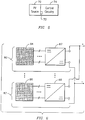
- FIG. 2 shows an example of a family of input I-V curves of a PV source at various illuminations levels (such as I-V curves 20, 22 24, 26, and 28).
- FIG. 2 further shows a graph of an example of the maximum power curve of the PV source (curve 30) that intersects the various I-V curves.
- FIG. 2 shows two example embodiments of possible input I-V curves for the power switching converter.
- a first example input I-V curve for the power switching converter may comprise a linear fit approximation 32, as may be based on a resistive function with a voltage offset along the voltage axis selected to bring this curve proximate to the maximum power point curve 30.
- a second example input I-V curve for the power switching converter may comprise a cubic fit approximation 34.
- a practical PV system may be substantially dependent on the illumination intensity, ambient temperature, location of installation, and combination of the foregoing. It has been observed that a linear fit through the origin of the I-V plane, while uncomplicated to realize and useful in many applications, may not necessarily provide the optimum input I-V curve for maximizing the power extraction from the PV source for cases subject to a wide range of operating conditions.
- the load converter input I-V curve has a relatively high slope (i.e., relatively high conductance) near the vicinity of the maximum power point of the I-V curve of the PV source.
- One example means to achieve this goal is to use a converter with a relatively sharp slope (e.g., providing a linear fit approximation) for its input I-V curve, which is also appropriately offset along the voltage axis so that the linear fit approximation intersects the PV source I-V curve near the maximum power point, as shown in FIG. 2 (input I-V curve 32).
- Another example means to accomplish the same goal is to use a converter with a curve of increasing slope, (e.g., a cubic fit approximation) also shown in FIG. 2 (input I-V curve 34).
- the description below will provide some example embodiments of switching converter topologies that may be used to realize such example input I-V curves in the power switching converter.
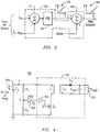
- FIG. 3 is a block diagram of an example implementation of a converter circuitry 40 configured to provide an input I-V curve having a linear fit with a voltage offset (such as input I-V curve 32 in FIG. 2 ).
- a proportional-integral-derivative (PID) controller 42 may be configured to process an output signal from summer 41 that combines a voltage signal (Vin) and a current signal (Iin), (as may be scaled by a suitable scaling factor (Req)) to output an error signal exhibiting a linear fit. See, for example, inset 45.
- PID proportional-integral-derivative
- a summer 46 combines the output signal from PID controller 42 and an offset voltage to generate a signal that (may be used as the pulse-width modulation (PWM) setpoint for the converter) exhibits the linear fit plus the voltage offset. See, for example, inset 48.
- PWM pulse-width modulation
- the circuitry illustrated in FIG. 3 can be implemented using the functional blocks available in a standard off-the-shelf PWM regulator (such as regulator part No. UC3854, commercially available from Texas Instruments) that can be implemented in a variety of single switch converter topologies, such as buck/boost, buck or boost converters.
- Temperature compensation can be optionally implemented by adjusting the offset reference as a function of a sensed parameter indicative of temperature of the PV source, for example.
- FIG. 4 is a block diagram of one example implementation of a PV system 60 with a converter 62 configured as a flyback converter to provide an input I-V curve having a cubic fit approximation, (such as input I-V curve 34 in FIG. 2 ).
- Converter 62 includes a pulse-width modulator (PWM) 64 that generates a pulse waveform of a predefined frequency and has a pulse duty cycle D proportional to a voltage V D supplied by a gain amplifier 66.
- PWM 64 pulse-width modulator
- the output of PWM 64 is coupled to a gating terminal of a semiconductor power switch Q 1 , such as a MOSFET switch.
- the current is proportional to the input voltage V, which generates a linear I-V curve.
- the input I-V curve of the converter various may be adjusted as a function of PV source temperature so that the input I-V curve, for example, shifts along the voltage axis as a function of PV source temperature.
- the sensing of a parameter indicative of temperature of the PV source may be accomplished with a thermistor or other temperature sensor on an integrated circuit, such as may be part of the converter circuitry. Since in some applications, the PV source and conveter circuitry may be integrated and thermally coupled to one another in a common package, this temperature sensing may be readily accomplished in multiple ways. For example, it is contemplated that in some applications, the temperature sensor may be a redundant, optionally shaded PV cell mounted with the other cells of the PV source.
- a section of the photovoltaic source may be masked to avoid a response due to illumination, and an electrical signal from the masked section may be used for sensing temperature of the photovoltaic source.
- an electrical signal from the masked section may be used for sensing temperature of the photovoltaic source.
- various combinations of physical proximity and conductive path characteristics may be used for achieving a desired thermal coupling for a given application.
- the thermal coupling may be configured so that in one example embodiment the PV source and converter circuitry may be at substantially the same temperature or optionally at a predictable temperature offset with respect to one another.
- a temperature sensor 72 may be an integral part of a respective integrated circuit in a converter circuitry 74.
- the temperature sensor may sense temperature variation of the integrated circuit (and thus of a PV source thermally coupled to the integrated circuit) by utilizing a thermally-sensitive voltage reference therein, such as a bandgap reference of a semiconductor device.
- the temperature sensor may utilize an external voltage reference coupled to drive a thermally-sensitive electrical component in the integrated circuit, such as a resistor, diode, capacitor, or a transistor.
- the temperature sensor may sense temperature in the respective integrated circuit by monitoring, for example, a diode current leakage. That is, some of the circuitry that is part of the integrated circuit (typically used for conditioning or processing the signals from the PV source) may be used for obtaining a temperature indication of the PV source.
- the temperature sensor may be assembled onto suitable pads built in the integrated circuit, such as a surface-mounted miniature thermistor mounted on diode pads.
- the temperature sensor need not be integral to a respective integrated circuit, since, for example, the temperature sensor may be disposed external to the integrated circuit, such as mounted on an outer surface thermally coupled to the integrated circuit.
- this thermally-sensitive electrical component e.g., functioning as a temperature sensor
- the photovoltaic source may include a first face exposed to illumination and a second face opposite the first face not exposed to illumination. It is contemplated that in this example embodiment the converter may be integrated with the photovoltaic source at the second face of the PV cell or PV module. That is, the non-illuminated face of the PV cell or PV module.
- an array of PV modules may be needed because a single PV module may not be capable of supplying enough power, as may be required in a given power application.
- Achieving power scaling in practical PV arrays has presented some difficulties. For instance, in known PV arrays, it may not be possible to continue to increment the number of PV modules that may be connected to achieve a desired power rating. This is due to the possibility that incompatibilities may develop between the respective input and output I-V characteristics of the converters to be connected.
- PV systems equipped with a maximum power point tracking algorithm such algorithms may be unable to determine the maximum power point of a plurality of PV modules, such as may occur when a subset of individual PV modules in a PV modular array become shaded.
- This partial shading modifies the shape of the composite I-V curve of the PV array in a manner that substantially increases the complexity of maximum power tracking such that there may be a need for determining both local and global maximum power point tracking algorithms.
- known PV arrays may be limited in the number of PV modules that can be interconnected to one another, and consequently may lack the ability to provide the desired power scalability.
- yet another advantage provided by converters with the input I-V curves embodying various aspects of the present invention is that the respective output I-V curves of such converters exhibit characteristic suitable for sharing electrical power when connected together to one another, as shown in FIG. 6 .
- This is conducive to combining the power output from multiple PV modules, such as modules 80 and 82 including respective PV sources 84 and 86.
- This benefit may be achieved when the PV load converter's input I-V curve is independent of the PV load converter's output, as is the case in connection with the example input I-V curves discussed above.
- each PV load converter will act as a power source, providing advantageous power scaling capabilities.
- Each converter becomes a power source and can be connected in any desired manner, such as in a series circuit, in a parallel circuit, or series/parallel circuit combinations, to other such converters that may be part of a PV modular array, provided the working load uses essentially all the power delivered by the PV sources.
Landscapes
- Engineering & Computer Science (AREA)
- Power Engineering (AREA)
- Life Sciences & Earth Sciences (AREA)
- Sustainable Development (AREA)
- Sustainable Energy (AREA)
- Physics & Mathematics (AREA)
- Electromagnetism (AREA)
- General Physics & Mathematics (AREA)
- Radar, Positioning & Navigation (AREA)
- Automation & Control Theory (AREA)
- Dc-Dc Converters (AREA)
- Control Of Electrical Variables (AREA)
Claims (8)
- Système photovoltaïque (60) comprenant :une source photovoltaïque (68) comprenant des caractéristiques génératrices de puissance définies par une famille de courbes tension-courant (20, 22, 24, 26, 28) comprenant des points de puissance électrique maximale sur une plage respective d'au moins l'une des suivantes pour la source photovoltaïque (68) :des intensités d'éclairage distinctes et des températures distinctes ;un réseau de diviseurs résistifs (R1, R2) pour détecter la tension de la source photovoltaïque (68) ;un amplificateur de gain (66) pour recevoir la tension détectée (Vsense) du réseau de diviseurs résistifs (R1, R2) et amplifier la tension détectée (Vsense) venant du réseau de diviseurs résistifs (R1, R2) ;un convertisseur de commutation (62) couplé à la source photovoltaïque (68), dans lequel le convertisseur de commutation (62) comprend une courbe tension-courant d'entrée ayant une relation fonctionnelle prédéfinie entre une tension d'entrée et un courant d'entrée, la courbe tension-courant d'entrée comprend une approximation d'ajustement cubique par rapport à au moins certains des points de puissance électrique maximale pour la source photovoltaïque (68), le convertisseur de commutation (62) comprenant en outre au moins un commutateur (Q1) et un modulateur de largeur d'impulsion (64) recevant la tension détectée amplifiée (Vsense) de l'amplificateur de gain (66) pour établir une relation directement proportionnelle entre un cycle opératoire du convertisseur de commutation (62) et la tension de la source photovoltaïque (68) et pour fournir des signaux de déclenchement au au moins un commutateur (Q1) pour faire fonctionner le convertisseur de commutateur (62) dans un mode de conduction discontinu pour établir une relation entre le courant d'entrée du convertisseur de commutation (62), la tension d'entrée du convertisseur de commutation (62) et un carré du cycle opératoire du convertisseur de commutation (62) qui est l'approximation d'ajustement cubique d'au moins certains des points de puissance électrique maximale sur les courbes tension-courant sans devoir effectuer de calculs de courant et de tension correspondant à une puissance maximale de la source photovoltaïque (68).
- Système photovoltaïque (60) selon la revendication 1, dans lequel le convertisseur de commutation (112) comprend un type de convertisseur choisi dans le groupe constitué d'un convertisseur (62) du type à retour de spot, à survolteur-dévolteur et à survolteur ou dévolteur.
- Système photovoltaïque (60) selon l'une quelconque des revendications précédentes, dans lequel le convertisseur (12) comprend un type de convertisseur (62) à retour de spot.
- Système photovoltaïque (60) selon l'une quelconque des revendications précédentes, comprenant une pluralité de convertisseurs de commutation (87, 88) couplés chacun pour recevoir de la puissance électrique d'une source photovoltaïque respective (84, 86), dans lequel chaque convertisseur individuel (87, 88) comprend une courbe tension-courant d'entrée ayant une relation fonctionnelle prédéfinie entre la tension d'entrée et le courant d'entrée configurée pour fournir une approximation par rapport à au moins certains des points de puissance électrique maximale pour la source photovoltaïque respective (84, 86) et dans lequel, en outre, chaque sortie de convertisseur individuelle (87, 88) est connectée l'une à l'autre pour former une combinaison de circuit de sorte qu'une gradation souhaitée de la puissance de sortie soit atteinte.
- Système photovoltaïque (60) selon la revendication 4, dans lequel la combinaison de circuit est choisie dans un groupe constitué d'un circuit en série, d'un circuit en parallèle et d'une combinaison des circuits précités.
- Système photovoltaïque (60) selon la revendication 4 ou 5, dans lequel chaque convertisseur individuel (87, 88) comprend un convertisseur CC-CC.
- Système photovoltaïque (60) selon l'une quelconque des revendications précédentes, dans lequel une section de la source photovoltaïque (68) est masquée pour éviter une réponse due à l'éclairage et dans lequel un signal électrique provenant de la section masquée est utilisé pour détecter la température de la source photovoltaïque (68)
- Système photovoltaïque selon l'une quelconque des revendications 1 à 6, dans lequel la source photovoltaïque (68) comprend une première face exposée à un éclairage et une seconde face opposée à la première face non exposée à l'éclairage et dans lequel le convertisseur (62) est intégré à la source photovoltaïque (68) sur sa seconde face.
Applications Claiming Priority (1)
| Application Number | Priority Date | Filing Date | Title |
|---|---|---|---|
| US11/736,125 US20080257397A1 (en) | 2007-04-17 | 2007-04-17 | System, method, and apparatus for extracting power from a photovoltaic source of electrical energy |
Publications (3)
| Publication Number | Publication Date |
|---|---|
| EP1983632A2 EP1983632A2 (fr) | 2008-10-22 |
| EP1983632A3 EP1983632A3 (fr) | 2015-08-05 |
| EP1983632B1 true EP1983632B1 (fr) | 2017-11-15 |
Family
ID=39705217
Family Applications (1)
| Application Number | Title | Priority Date | Filing Date |
|---|---|---|---|
| EP08154511.3A Active EP1983632B1 (fr) | 2007-04-17 | 2008-04-15 | Système, procédé et appareil pour extraire de l'énergie à partir d'une source photovoltaïque d'énergie électrique |
Country Status (5)
| Country | Link |
|---|---|
| US (2) | US20080257397A1 (fr) |
| EP (1) | EP1983632B1 (fr) |
| JP (1) | JP5276349B2 (fr) |
| KR (1) | KR101465796B1 (fr) |
| CN (1) | CN101290527B (fr) |
Families Citing this family (39)
| Publication number | Priority date | Publication date | Assignee | Title |
|---|---|---|---|---|
| CN101295872B (zh) | 2007-04-28 | 2010-04-14 | 昂宝电子(上海)有限公司 | 为功率转换器提供过电流和过功率保护的系统和方法 |
| US20100176773A1 (en) * | 2006-03-31 | 2010-07-15 | Antoine Capel | Circuit and method for controlling the point of maximum power for solar energy source and solar generator incorporating said circuit |
| US8537572B2 (en) * | 2007-09-28 | 2013-09-17 | Enphase Energy, Inc. | Method and apparatus for providing power conversion using an interleaved flyback converter with automatic balancing |
| WO2009055474A1 (fr) | 2007-10-23 | 2009-04-30 | And, Llc | Systèmes d'alimentation à haute fiabilité et convertisseurs d'énergie solaire |
| CA2737134C (fr) | 2007-10-15 | 2017-10-10 | Ampt, Llc | Systemes pour energie solaire hautement efficace |
| JP5026374B2 (ja) * | 2008-09-05 | 2012-09-12 | 日本電信電話株式会社 | 電力制御方法および電力制御装置 |
| US20100213768A1 (en) * | 2009-02-24 | 2010-08-26 | Alex Faveluke | Apparatus for photovoltaic power generation |
| WO2010120315A1 (fr) | 2009-04-17 | 2010-10-21 | Ampt, Llc | Procédés et appareil pour le fonctionnement adaptatif de systèmes à énergie solaire |
| US9466737B2 (en) | 2009-10-19 | 2016-10-11 | Ampt, Llc | Solar panel string converter topology |
| US8859884B2 (en) | 2009-10-19 | 2014-10-14 | Helios Focus Llc | Solar photovoltaic module safety shutdown system |
| US9941421B2 (en) | 2009-10-19 | 2018-04-10 | Helios Focus Llc | Solar photovaltaic module rapid shutdown and safety system |
| US10121913B2 (en) | 2009-10-19 | 2018-11-06 | Helios Focus Llc | Solar photovoltaic module safety shutdown system |
| US7990743B2 (en) * | 2009-10-20 | 2011-08-02 | General Electric Company | System and method for decreasing solar collector system losses |
| US7855906B2 (en) * | 2009-10-26 | 2010-12-21 | General Electric Company | DC bus voltage control for two stage solar converter |
| US8421400B1 (en) * | 2009-10-30 | 2013-04-16 | National Semiconductor Corporation | Solar-powered battery charger and related system and method |
| KR101311528B1 (ko) * | 2009-12-11 | 2013-09-25 | 한국전자통신연구원 | 태양전지의 최대전력 추출 장치 및 방법 |
| US9342088B2 (en) | 2009-12-31 | 2016-05-17 | Sunpower Corporation | Power point tracking |
| US8050062B2 (en) | 2010-02-24 | 2011-11-01 | General Electric Company | Method and system to allow for high DC source voltage with lower DC link voltage in a two stage power converter |
| CN101834458B (zh) * | 2010-05-10 | 2012-10-17 | 重庆大学 | 基于动态拓扑结构的光伏最大能量收集装置及其方法 |
| TWI428724B (zh) | 2010-11-03 | 2014-03-01 | Univ Nat Cheng Kung | Discontinuous conduction current mode of the maximum power limiting PV system converter |
| US9553501B2 (en) | 2010-12-08 | 2017-01-24 | On-Bright Electronics (Shanghai) Co., Ltd. | System and method providing over current protection based on duty cycle information for power converter |
| CN102545567B (zh) | 2010-12-08 | 2014-07-30 | 昂宝电子(上海)有限公司 | 为电源变换器提供过电流保护的系统和方法 |
| AU2011355888B2 (en) * | 2011-01-20 | 2015-07-16 | Kabushiki Kaisha Toshiba | Photovoltaic system and power supply system |
| JP6003048B2 (ja) * | 2011-11-29 | 2016-10-05 | ソニー株式会社 | 発電装置 |
| CN103294102A (zh) * | 2012-11-02 | 2013-09-11 | 许昌学院电气信息工程学院 | 一种基于温度检测的太阳能cvt控制方法 |
| US9397497B2 (en) | 2013-03-15 | 2016-07-19 | Ampt, Llc | High efficiency interleaved solar power supply system |
| CN103401424B (zh) | 2013-07-19 | 2014-12-17 | 昂宝电子(上海)有限公司 | 用于调整电源变换系统的输出电流的系统和方法 |
| CN108809100B (zh) | 2014-04-18 | 2020-08-04 | 昂宝电子(上海)有限公司 | 用于调节电源变换系统的输出电流的系统和方法 |
| US9584005B2 (en) | 2014-04-18 | 2017-02-28 | On-Bright Electronics (Shanghai) Co., Ltd. | Systems and methods for regulating output currents of power conversion systems |
| TWI527497B (zh) * | 2014-08-13 | 2016-03-21 | wen-qin Xiao | Light - emitting diode drive system and control module |
| CN104660022B (zh) | 2015-02-02 | 2017-06-13 | 昂宝电子(上海)有限公司 | 为电源变换器提供过流保护的系统和方法 |
| KR101670331B1 (ko) * | 2015-04-27 | 2016-11-09 | 엔지유 인터내셔날 ㈜ | 솔라셀 어닝 시스템 및 이를 이용한 최대 전력 생산 방법 |
| CN106981985B (zh) | 2015-05-15 | 2019-08-06 | 昂宝电子(上海)有限公司 | 用于电源转换系统中的输出电流调节的系统和方法 |
| US10270334B2 (en) | 2015-05-15 | 2019-04-23 | On-Bright Electronics (Shanghai) Co., Ltd. | Systems and methods for output current regulation in power conversion systems |
| CN110377098B (zh) * | 2018-04-13 | 2021-01-26 | 立锜科技股份有限公司 | 可追踪最大功率点的电源转换装置及其中的控制方法 |
| CN110994671B (zh) * | 2019-11-25 | 2023-04-28 | 国网四川省电力公司电力科学研究院 | 一种基于matlab的小型独立光伏发电仿真模型 |
| CN110879631B (zh) * | 2019-11-27 | 2022-04-29 | 深圳供电局有限公司 | 一种跟踪太阳能电池最大功率点的方法 |
| CN112152307B (zh) * | 2020-09-01 | 2022-02-01 | 宁波大学 | 一种自供电的振动能、热能和光能协同收集系统 |
| CA3156943A1 (fr) | 2021-07-02 | 2023-01-02 | Les Produits Sunforce Inc. | Lampe murale solaire |
Family Cites Families (17)
| Publication number | Priority date | Publication date | Assignee | Title |
|---|---|---|---|---|
| US4580090A (en) * | 1983-09-16 | 1986-04-01 | Motorola, Inc. | Maximum power tracker |
| JPS6154820A (ja) * | 1984-08-23 | 1986-03-19 | シャープ株式会社 | 光発電システムの直交変換装置 |
| JPS63136117A (ja) * | 1986-11-27 | 1988-06-08 | Nissin Electric Co Ltd | 系統連系太陽光発電装置のインバ−タ制御方式 |
| PH25015A (en) * | 1986-12-19 | 1991-01-28 | Stuart Maxwell Watkins | Electrical power transfer apparatus |
| FR2634293B2 (fr) * | 1988-01-29 | 1990-10-19 | Centre Nat Etd Spatiales | Systeme de regulation du point de fonctionnement d'une alimentation a courant continu en zone de caracteristique generateur de tension ou de courant imposee |
| JP2771096B2 (ja) * | 1993-06-11 | 1998-07-02 | キヤノン株式会社 | 電力制御装置、電力制御方法及び電力発生装置 |
| JP3402388B2 (ja) * | 1993-09-01 | 2003-05-06 | 株式会社安川電機 | 太陽電池の最大電力動作点判定方法 |
| JP3382434B2 (ja) * | 1995-09-22 | 2003-03-04 | キヤノン株式会社 | 電池電源の電圧制御装置および電圧制御方法 |
| JP3647209B2 (ja) * | 1997-06-30 | 2005-05-11 | キヤノン株式会社 | 太陽電池特性の測定方法 |
| US6057665A (en) * | 1998-09-18 | 2000-05-02 | Fire Wind & Rain Technologies Llc | Battery charger with maximum power tracking |
| JP2000181555A (ja) * | 1998-12-11 | 2000-06-30 | Ntt Power & Building Facilities Inc | 太陽光発電システムおよびその制御方法 |
| JP3809316B2 (ja) * | 1999-01-28 | 2006-08-16 | キヤノン株式会社 | 太陽光発電装置 |
| DE10107600C1 (de) * | 2001-02-17 | 2002-08-22 | Saint Gobain | Verfahren zum Betreiben eines photovoltaischen Solarmoduls und photovoltaischer Solarmodul |
| US20030096642A1 (en) * | 2001-11-19 | 2003-05-22 | Jerry Bessa | Case for cellular phone |
| JP2004208494A (ja) * | 2002-12-11 | 2004-07-22 | Canon Inc | 信号発生器の制御方法 |
| JP3548765B1 (ja) * | 2003-03-11 | 2004-07-28 | オムロン株式会社 | 最大電力追従制御装置 |
| WO2004100344A2 (fr) * | 2003-05-02 | 2004-11-18 | Ballard Power Systems Corporation | Procede et appareil de suivi de point de courant maximum pour des inverseurs, par exemple, dans des applications photovoltaiques |
-
2007
- 2007-04-17 US US11/736,125 patent/US20080257397A1/en not_active Abandoned
-
2008
- 2008-04-09 JP JP2008100904A patent/JP5276349B2/ja active Active
- 2008-04-15 EP EP08154511.3A patent/EP1983632B1/fr active Active
- 2008-04-16 KR KR1020080035007A patent/KR101465796B1/ko active IP Right Grant
- 2008-04-17 CN CN200810092236.7A patent/CN101290527B/zh active Active
-
2010
- 2010-08-12 US US12/854,947 patent/US8227683B2/en active Active
Non-Patent Citations (1)
| Title |
|---|
| None * |
Also Published As
| Publication number | Publication date |
|---|---|
| KR101465796B1 (ko) | 2014-11-26 |
| US20110036387A1 (en) | 2011-02-17 |
| CN101290527B (zh) | 2014-01-29 |
| EP1983632A2 (fr) | 2008-10-22 |
| EP1983632A3 (fr) | 2015-08-05 |
| JP2008269596A (ja) | 2008-11-06 |
| JP5276349B2 (ja) | 2013-08-28 |
| US20080257397A1 (en) | 2008-10-23 |
| US8227683B2 (en) | 2012-07-24 |
| KR20080093894A (ko) | 2008-10-22 |
| CN101290527A (zh) | 2008-10-22 |
Similar Documents
| Publication | Publication Date | Title |
|---|---|---|
| EP1983632B1 (fr) | Système, procédé et appareil pour extraire de l'énergie à partir d'une source photovoltaïque d'énergie électrique | |
| An et al. | Design of a single-switch DC/DC converter for a PV-battery-powered pump system with PFM+ PWM control | |
| Tofoli et al. | Comparative study of maximum power point tracking techniques for photovoltaic systems | |
| Hua et al. | Study of maximum power tracking techniques and control of DC/DC converters for photovoltaic power system | |
| Swiegers et al. | An integrated maximum power point tracker for photovoltaic panels | |
| US20060132102A1 (en) | Maximum power point tracking charge controller for double layer capacitors | |
| WO2006002380A2 (fr) | Systemes et procedes de poursuite du pic d'energie d'un microcapteur photovoltaique | |
| JP2013161139A (ja) | 電力供給システムおよび電源装置 | |
| Dursun et al. | Analysis and performance comparison of DC-DC power converters used in photovoltaic systems | |
| Zhao et al. | A digitally implemented photovoltaic simulator with a double current mode controller | |
| Alli et al. | MPPT and output voltage control of Photovoltaic systems using a Single-Switch DC-DC converter | |
| Shoumi et al. | Design of the CUK converter with PI controller for battery charging | |
| Bodele et al. | Modular battery-integrated bidirectional single-stage DC–DC converter for solar PV based DC Nano-grid application | |
| Anshory et al. | Optimization DC-DC boost converter of BLDC motor drive by solar panel using PID and firefly algorithm | |
| Alagammal et al. | Combination of modified P&O with power management circuit to exploit reliable power from autonomous PV-battery systems | |
| Jyothi et al. | Implementation of modified SEPIC converter for renewable energy built DC microgrids | |
| Wang et al. | A 200W MPPT boost converter for BIPV applications with integrated controller | |
| US20220216792A1 (en) | Method and Apparatus for Bypass and Shutdown of a Power Device | |
| El-Shater et al. | Energy flow and management of a hybrid wind/PV/fuel cell generation system | |
| de Lima et al. | Design and modeling of a transformerless hybrid inverter system using a fuel cell as energy storage element for microgrids with sensitive loads | |
| Siouane et al. | A thermoelectric energy harvester with a single switch unified control for autonomous applications | |
| KR20060091672A (ko) | 태양광시스템의 컨버터 및 그 제어장치 | |
| Chung et al. | A maximum power point tracking and voltage regulated dual-chip system for single-cell photovoltaic energy harvesting | |
| Munisekhar et al. | The Fastest MPPT Tracking Algorithm for a PV array fed BLDC Motor Driven Air Conditioning system | |
| Poompavai et al. | Control Strategies Applied in Solar-Powered Water Pumping System—A Review |
Legal Events
| Date | Code | Title | Description |
|---|---|---|---|
| PUAI | Public reference made under article 153(3) epc to a published international application that has entered the european phase |
Free format text: ORIGINAL CODE: 0009012 |
|
| AK | Designated contracting states |
Kind code of ref document: A2 Designated state(s): AT BE BG CH CY CZ DE DK EE ES FI FR GB GR HR HU IE IS IT LI LT LU LV MC MT NL NO PL PT RO SE SI SK TR |
|
| AX | Request for extension of the european patent |
Extension state: AL BA MK RS |
|
| PUAL | Search report despatched |
Free format text: ORIGINAL CODE: 0009013 |
|
| AK | Designated contracting states |
Kind code of ref document: A3 Designated state(s): AT BE BG CH CY CZ DE DK EE ES FI FR GB GR HR HU IE IS IT LI LT LU LV MC MT NL NO PL PT RO SE SI SK TR |
|
| AX | Request for extension of the european patent |
Extension state: AL BA MK RS |
|
| RIC1 | Information provided on ipc code assigned before grant |
Ipc: H02J 3/38 20060101ALI20150630BHEP Ipc: H01L 31/02 20060101ALI20150630BHEP Ipc: G05F 1/67 20060101AFI20150630BHEP Ipc: H02M 3/04 20060101ALI20150630BHEP |
|
| 17P | Request for examination filed |
Effective date: 20160205 |
|
| RBV | Designated contracting states (corrected) |
Designated state(s): AT BE BG CH CY CZ DE DK EE ES FI FR GB GR HR HU IE IS IT LI LT LU LV MC MT NL NO PL PT RO SE SI SK TR |
|
| AKX | Designation fees paid |
Designated state(s): DE ES FR IT |
|
| AXX | Extension fees paid |
Extension state: BA Extension state: AL Extension state: MK Extension state: RS |
|
| REG | Reference to a national code |
Ref country code: DE Ref legal event code: R079 Ref document number: 602008052943 Country of ref document: DE Free format text: PREVIOUS MAIN CLASS: H02J0007350000 Ipc: G05F0001670000 |
|
| RIC1 | Information provided on ipc code assigned before grant |
Ipc: G05F 1/67 20060101AFI20160808BHEP Ipc: H02J 3/38 20060101ALI20160808BHEP Ipc: H02M 3/04 20060101ALI20160808BHEP Ipc: H01L 31/02 20060101ALI20160808BHEP |
|
| GRAP | Despatch of communication of intention to grant a patent |
Free format text: ORIGINAL CODE: EPIDOSNIGR1 |
|
| INTG | Intention to grant announced |
Effective date: 20170418 |
|
| GRAS | Grant fee paid |
Free format text: ORIGINAL CODE: EPIDOSNIGR3 |
|
| GRAJ | Information related to disapproval of communication of intention to grant by the applicant or resumption of examination proceedings by the epo deleted |
Free format text: ORIGINAL CODE: EPIDOSDIGR1 |
|
| GRAL | Information related to payment of fee for publishing/printing deleted |
Free format text: ORIGINAL CODE: EPIDOSDIGR3 |
|
| INTC | Intention to grant announced (deleted) | ||
| GRAR | Information related to intention to grant a patent recorded |
Free format text: ORIGINAL CODE: EPIDOSNIGR71 |
|
| GRAA | (expected) grant |
Free format text: ORIGINAL CODE: 0009210 |
|
| AK | Designated contracting states |
Kind code of ref document: B1 Designated state(s): DE ES FR IT |
|
| INTG | Intention to grant announced |
Effective date: 20171011 |
|
| REG | Reference to a national code |
Ref country code: DE Ref legal event code: R096 Ref document number: 602008052943 Country of ref document: DE |
|
| PG25 | Lapsed in a contracting state [announced via postgrant information from national office to epo] |
Ref country code: ES Free format text: LAPSE BECAUSE OF FAILURE TO SUBMIT A TRANSLATION OF THE DESCRIPTION OR TO PAY THE FEE WITHIN THE PRESCRIBED TIME-LIMIT Effective date: 20171115 |
|
| REG | Reference to a national code |
Ref country code: DE Ref legal event code: R097 Ref document number: 602008052943 Country of ref document: DE |
|
| PG25 | Lapsed in a contracting state [announced via postgrant information from national office to epo] |
Ref country code: IT Free format text: LAPSE BECAUSE OF FAILURE TO SUBMIT A TRANSLATION OF THE DESCRIPTION OR TO PAY THE FEE WITHIN THE PRESCRIBED TIME-LIMIT Effective date: 20171115 |
|
| PLBE | No opposition filed within time limit |
Free format text: ORIGINAL CODE: 0009261 |
|
| STAA | Information on the status of an ep patent application or granted ep patent |
Free format text: STATUS: NO OPPOSITION FILED WITHIN TIME LIMIT |
|
| 26N | No opposition filed |
Effective date: 20180817 |
|
| PG25 | Lapsed in a contracting state [announced via postgrant information from national office to epo] |
Ref country code: FR Free format text: LAPSE BECAUSE OF NON-PAYMENT OF DUE FEES Effective date: 20180430 |
|
| P01 | Opt-out of the competence of the unified patent court (upc) registered |
Effective date: 20230522 |
|
| PGFP | Annual fee paid to national office [announced via postgrant information from national office to epo] |
Ref country code: DE Payment date: 20230321 Year of fee payment: 16 |
|
| REG | Reference to a national code |
Ref country code: DE Ref legal event code: R081 Ref document number: 602008052943 Country of ref document: DE Owner name: GE GRID SOLUTIONS LLC, ATLANTA, US Free format text: FORMER OWNER: GENERAL ELECTRIC COMPANY, SCHENECTADY, NY, US |