EP1983540A2 - Benutzerschnittstelle für einen Zeitgeber - Google Patents
Benutzerschnittstelle für einen Zeitgeber Download PDFInfo
- Publication number
- EP1983540A2 EP1983540A2 EP08005968A EP08005968A EP1983540A2 EP 1983540 A2 EP1983540 A2 EP 1983540A2 EP 08005968 A EP08005968 A EP 08005968A EP 08005968 A EP08005968 A EP 08005968A EP 1983540 A2 EP1983540 A2 EP 1983540A2
- Authority
- EP
- European Patent Office
- Prior art keywords
- dial
- captured tripper
- captured
- tripper
- timer
- Prior art date
- Legal status (The legal status is an assumption and is not a legal conclusion. Google has not performed a legal analysis and makes no representation as to the accuracy of the status listed.)
- Withdrawn
Links
Images
Classifications
-
- H—ELECTRICITY
- H01—ELECTRIC ELEMENTS
- H01H—ELECTRIC SWITCHES; RELAYS; SELECTORS; EMERGENCY PROTECTIVE DEVICES
- H01H43/00—Time or time-programme switches providing a choice of time-intervals for executing one or more switching actions and automatically terminating their operation after the programme is completed
- H01H43/02—Details
- H01H43/04—Means for time setting
- H01H43/06—Means for time setting comprising separately adjustable parts for each programme step, e.g. with tappets
- H01H43/065—Means for time setting comprising separately adjustable parts for each programme step, e.g. with tappets using cams or discs supporting a plurality of individually programmable elements (Schaltreiter)
-
- G—PHYSICS
- G04—HOROLOGY
- G04C—ELECTROMECHANICAL CLOCKS OR WATCHES
- G04C23/00—Clocks with attached or built-in means operating any device at preselected times or after preselected time-intervals
- G04C23/02—Constructional details
- G04C23/08—Programming means
-
- H—ELECTRICITY
- H01—ELECTRIC ELEMENTS
- H01H—ELECTRIC SWITCHES; RELAYS; SELECTORS; EMERGENCY PROTECTIVE DEVICES
- H01H43/00—Time or time-programme switches providing a choice of time-intervals for executing one or more switching actions and automatically terminating their operation after the programme is completed
- H01H43/10—Time or time-programme switches providing a choice of time-intervals for executing one or more switching actions and automatically terminating their operation after the programme is completed with timing of actuation of contacts due to a part rotating at substantially constant speed
Definitions
- the technical field of the present disclosure relates to a user interface for a timer such as an electromechanical timer.
- Timer switches whether mechanical, electrical, or electromechanical, have been used in a wide variety of indoor and outdoor applications. For example, one popular use of such timers is to switch lights on and off. Typical timers permit the on and off times to be independently controlled so that a load, such as the above mentioned lights, is switched on at a first independently set time and is switched off at a later second independently set time.
- timers In order to select desired on and off times, it is known to equip timers with pins or trippers whose positions are individually selectable so to trip one or more switches on and off at the desired times. Unfortunately, these known timers have a number of drawbacks.
- a timer is provided with multiple on pins or trippers and multiple off pins or trippers so that more than one on time and more than one off time may be set, and if a user desires to set only one on time and only one off time, the user must remove from the timer the pins or trippers that are not being used. Not only is the removal of these excess pins or trippers an unnecessary nuisance, but these removed pins or trippers can be mislaid so that they are not readily available should the user later desire to set additional on and off times.
- pins or trippers of known timers must be removed from and reattached to the timer whenever a user chooses to adjust the on and off times. Pins or trippers can be dropped during their removal and reattachment, which at a minimum is a nuisance. Worse, dropped pins or trippers can be lost, especially when timers are used outdoors.
- the timer described below overcomes one or more of these or other problems.
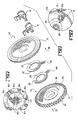
- a timer 10 as shown in Figures 1-5 includes first and second dials 12 and 14, first and second captured trippers 16 and 18, and first and second retainers 20 and 22.
- the first and second dials 12 and 14 may be keyed together so that a timer movement moves the first and second dials 12 and 14 in unison.
- the movement of the timer 10 may be a mechanical, electrical, or electromechanical movement that is arranged to rotate the first and second dials 12 and 14 in the direction of the arrow shown in Figure 2 .
- the first dial 12 has first and second sides 24 and 26.
- the first side 24 includes an annular outer ring 28, an annular inner ring 30, an annular ramp shaped ring 32, and an annular groove 34.
- the annular outer ring 28 and the annular inner ring 30 are disposed in planes that are parallel to and offset from one another.
- the annular ramp shaped ring 32 is between the annular outer ring 28 and the annular groove 34.
- the annular groove 34 is between the annular ramp shaped ring 32 and the annular inner ring 30.
- the first dial 12 has an annular peripheral edge 36 extending between the first and second sides 24 and 26 and that overhangs the second side 26 by a small amount. Teeth 38 are disposed annularly around the second side 26 near the annular peripheral edge 36.
- the first dial 12 also has a hub 42 and a central hole 44 extending through the hub 42.
- the second dial 14 has first and second sides 50 and 52.
- the first side 50 of the second dial 14 faces the second side 26 of the first dial 12 when the timer 10 is assembled.
- the first side 50 is formed with an annular well 54 surrounded by an annular rim 56 at the peripheral edge of the second dial 14. Teeth 58 are provided around the outer perimeter of the annular rim 56.
- the second dial 14 also has a hub 60 and a hole 62 through the hub 60. The hole 62 of the second dial 14 aligns with the hole 42 of the first dial 12 when the timer 10 is assembled as shown in Figure 3 .
- the first captured tripper 16 is formed as an on tripper since it cooperates with a first cam portion to close a pair of switch contacts
- the second captured tripper 18 is formed as an off tripper since it cooperates with a second cam portion to open the pair of switch contacts.
- the first captured tripper 16 has a head 70 joined to a barrel 72 by a neck 74.
- a recess 76 is formed at the neck 74 between the head 70 and the barrel 72.
- the end of the head 70 is formed with a protrusion 78 that engages the annular groove 34 when the first captured tripper 16 is in its active position.
- a horseshoe shaped bracket 80 is attached to an arm 82 that depends from the barrel 72 near the neck 74 of the first captured tripper 16.
- the arm 82 is L-shaped having first and second arm portions 82a and 82b.
- the first arm portion 82a is formed at a right angle to the barrel 72
- the second arm portion 82b is formed at a right angle to the first arm portion 82a so that the second arm portion 82b is parallel to the barrel 72.
- the first captured tripper 16 further includes a first tooth 84 attached to the barrel 72 on one side of the arm 82, a second tooth 86 attached to the barrel 72 on the opposite side of the arm 82, and a switch operator 88 at the end of the barrel 72.
- the first tooth 84 meshes with the teeth 38 of the first dial 12 when the first captured tripper 16 is in its active position
- the second tooth 86 meshes with the teeth 58 of the second dial 14 when the first captured tripper 16 is in its active position
- the switch operator 88 cooperates with the first cam portion to close the switch contacts when the first captured tripper 16 is in its active position and the first and second dials 12 and 14 are rotated sufficiently for the switch operator 88 to engage an appropriate lobe on the first cam portion.
- the first retainer 20 has a hole 92 that aligns with the hole 42 of the first dial 12 and the hole 62 of the second dial 14 when the timer 10 is assembled as shown in Figure 3 .
- a tab 94 extends from the outer periphery of the first retainer 20 away from the hole 92.
- the tab 94 has a slot 96 that receives an arm 98 of the bracket 80 of the first captured tripper 16 and that permits the first captured tripper 16 to move between its active and inactive positions.
- the first captured tripper 16 is captured to the timer 10 when the first and second dials 12 and 14 are mated as shown in Figure 3 .
- the horseshoe shaped bracket 80 and the second arm portion 82b ensure that the first captured tripper 16 is captured to the timer 10 when the first and second dials 12 and 14 are mated so that the first captured tripper cannot become separated from the timer 10, even when the first captured tripper 16 is in its inactive position.
- the second captured tripper 18 is formed similarly to the first captured tripper 16, differing only in that the barrel 72' of the second captured tripper 18 is longer than the barrel 72 of the first captured tripper 16. Therefore, the switch operator 88 of the first captured tripper 16 but not the switch operator 88' of the second captured tripper 18 cooperates with the first cam portion to close the switch contacts, and the switch operator 88' of the second captured tripper 18 but not the switch operator 88 of the first captured tripper 16 cooperates with the second cam portion to open the switch contacts.
- the second captured tripper 18 is snapped onto the first dial 12 so that its protrusion 78' is against the annular ramp shaped ring 32, so that its recess 76' receives the annular edge 36 of the first dial 12, and so that its arm 82' snugly engages the second side 26 of the first dial 12.
- This position of the second captured tripper 18 is the inactive position.
- the second retainer 22 is then inserted onto the first dial 12 so that its hole 92' receives the hub 42 of the first dial 12 and so that its slot 96' receives the arm 98' of the bracket 80' of the second captured tripper 18.
- the first captured tripper 16 and the first retainer 20 are similarly applied to the first dial 12.
- the second dial 14 is then applied to the first dial 12 so that the hub 42 of the first dial 12 is received within the hub 60 of the second dial 14.
- the first and second dials 12 and 14 are keyed together so that the teeth 38 of the first dial 12 are aligned with the teeth 58 of the second dial 14.
- the inside perimeter of the hub 60 of the second dial 14 may have a ridge
- the outside perimeter of the hub 42 of the first dial 12 may have a slot.
- the ridge and slot extend along an axis that is parallel to the center axis of the holes 44 and 62. Accordingly, when the second dial 14 is applied to the first dial 12 so that the hub 42 of the first dial 12 is received within the hub 60 of the second dial 14, the ridge slides into and mates with the slot.
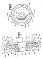
- Figure 3 shows the first captured tripper 16 in its active position and the second captured tripper 18 in its inactive position.
- first captured tripper 16 When the first captured tripper 16 is in its active position, its protrusion 78 is received in the annular groove 34 of the first dial 12, its first tooth 84 meshes with the teeth 38 of the first dial 12, and its second tooth 86 meshes with the teeth 58 of the second dial 14.
- the protrusion 78 of the first captured tripper 16 is engaged within the annular groove 34 of the first dial 12, because the first tooth 84 of the first captured tripper 16 meshes with the teeth 38 of the first dial 12, because the second tooth 86 of the first captured tripper 16 meshes with the teeth 58 of the second dial 14, and because the first and second dials 12 and 14 are keyed together and thereby cannot rotate independently of one another, the first captured tripper 16 is locked into position on the first dial 12 and cannot rotate independently of the first dial 12. In its active position, the first captured tripper 16 is in position to close the switch when the first and second dials 12 rotate sufficiently that the switch operator 88 engages the first cam portion.
- the user To move the first captured tripper 16 to its active position on the first dial 12, the user simply pushes the first captured tripper 16 in a direction perpendicularly toward the hubs 42 and 60. Doing so causes the protrusion 78 of the first captured tripper 16 to ride along the annular ramp shaped ring 32 and engage the annular groove 34 of the first dial 12, causes the first tooth 84 of the first captured tripper 16 to mesh with the teeth 38 of the first dial 12, and causes the second tooth 86 of the first captured tripper 16 to mesh with the teeth 58 of the second dial 14. The first captured tripper 16 would then have the active position with respect to the first dial 12 exemplified by the position of the first captured tripper 16 as shown in Figure 3 .
- the user To move the first captured tripper 16 to its inactive position on the first dial 12, the user simply pulls the first captured tripper 16 in a direction perpendicularly away from the hubs 42 and 60. Doing so causes the protrusion 78 of the first captured tripper 16 to disengage from the annular groove 34 of the first dial 12 and ride along the annular ramp shaped ring 32, causes the first tooth 84 of the first captured tripper 16 to move out of the teeth 38 of the first dial 12, and causes the second tooth 86 of the first captured tripper 16 to move out of the teeth 58 of the second dial 14. The first captured tripper 16 would then have the inactive position with respect to the first dial 12 exemplified by the position of the second captured tripper 18 as shown in Figure 3 .
- the first captured tripper 16 is free to move around the periphery of the first dial 12 even though the first dial 12 is stationary. As the first captured tripper 16 moves around the periphery of the first dial 12, the retainer 20 rotates about the hubs 42 and 60. Thus, the first captured tripper 16 may be moved to a new position relative to the first dial 12. Moreover, even though the first captured tripper 16 is free to move around the periphery of the first dial 12, the first captured tripper 16 is still captured to the timer 10 as discussed above. Furthermore, when the first captured tripper 16 is in its inactive position, the first captured tripper 16 is not in position to engage the first cam portion.
- first and second captured trippers 16 and 18 when not in their active positions are allowed to move freely relative to the first dial 12 and yet are captured to the timer 10 as explained above so that the first and second captured trippers 16 and 18 cannot be separated from the timer 10 without disassembling the timer 10. Therefore, the first and second captured trippers 16 and 18 when not in use to control the switch cannot be accidentally lost from the timer 10.
- the retainers 20 and 22 rotate about the hubs 42 and 60 as their corresponding first and second captured trippers 16 and 18 move about the first dial 12, At the same time, the retainers 20 and 22 maintain the orientation of the first and second captured trippers 16 and 18 on the first dial 12 so that the first and second teeth 84 can properly mate with the corresponding teeth 38 and 58 on the first and second dials 12 and 14.
- the retainers 16 and 18 insure that the axes along the length of the heads 70 and 70' of the respective retainers 16 and 18 as viewed in Figure 2 always intersect the center axis of the hole 42. In this manner, the retainers 16 and 18 prevent the first and second captured trippers 16 and 18 from becoming canted on the first dial 12 so that the teeth 84 and 86 are improperly oriented with respect to the corresponding teeth 38 and 58.
- the timer 10 can be easily provided with more than two captured trippers. In this case, a retainer is added for each of the additional captured trippers. If the user desires to use only one pair of on and off captured trippers to operate the switch so as to control a load, the user simply moves the unused on and off captured trippers to the inactive position shown by the position of the second captured tripper 18 in Figure 3 . For example, if the timer 10 is provided with two on captured trippers and two off captured trippers, and if the user desires to use only one pair of on and off captured trippers to operate the switch so as to control a load, the user moves one on captured tripper and one off captured tripper to the active position shown by the position of the first captured tripper 16 in Figure 3 . and moves the unused on captured tripper and the unused off captured tripper to the inactive position shown by the position of the second captured tripper 18 in Figure 3 .
- a cam 100 has first and second cam portions 102 and 104 at one end thereof.
- the first and second cam portions 102 and 104 rotate in unison under action of the first and second captured trippers 16 and 18 to control the position of a movable switch blade 106 with respect to a stationary switch blade 108.
- the first cam portion 102 has lobes 110
- the second cam portion 104 has lobes 112.
- the switch operator 88 of the captured tripper 16 moves into contact with the lobes 110 and rotates the first and second cam portions 102 and 104 and the cam 100.
- the switch operator 88' of the captured tripper 18 moves into contact with the lobes 112 and rotates the first and second cam portions 102 and 104 and the cam 100.
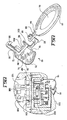
- FIG. 7 illustrates the position of the cam 100 and switch controllers 114 when the first captured tripper 16 has rotated the cam 100 to the switch on position.
- the switch on position the movable switch blade 106 is allowed to fall into the gap between two adjacent switch controllers 114 so that the movable switch blade 106 engages the stationary switch blade 108.
- the cam 100 assumes the switch off position.
- the switch off position the movable switch blade 106 rides up on one of the switch controllers 114 so that the movable switch blade 106 disengages from the stationary switch blade 108.
- the first captured tripper 16 drives the switch contacts 106 and 108 to their closed position
- the second captured tripper 18 drives the switch contacts 106 and 108 to their open position
- the first captured tripper 16 may be arranged to drive the switch contacts 106 and 108 to their open position
- the second captured tripper 18 may be arranged to drive the switch contacts 106 and 108 to their closed position.
- timer 10 may be provided with a cover 120 ( Figure 5 ) that provides hour or actual time marks so that the first and second captured trippers 16 and 18 may be positioned on the first dial 12 relative to one another based on time.
Landscapes
- Physics & Mathematics (AREA)
- General Physics & Mathematics (AREA)
- Measurement Of Predetermined Time Intervals (AREA)
Applications Claiming Priority (1)
| Application Number | Priority Date | Filing Date | Title |
|---|---|---|---|
| US11/737,820 US20080259736A1 (en) | 2007-04-20 | 2007-04-20 | User interface for timer |
Publications (2)
| Publication Number | Publication Date |
|---|---|
| EP1983540A2 true EP1983540A2 (de) | 2008-10-22 |
| EP1983540A3 EP1983540A3 (de) | 2009-11-04 |
Family
ID=39529714
Family Applications (1)
| Application Number | Title | Priority Date | Filing Date |
|---|---|---|---|
| EP08005968A Withdrawn EP1983540A3 (de) | 2007-04-20 | 2008-03-28 | Benutzerschnittstelle für einen Zeitgeber |
Country Status (4)
| Country | Link |
|---|---|
| US (1) | US20080259736A1 (de) |
| EP (1) | EP1983540A3 (de) |
| CA (1) | CA2623925A1 (de) |
| MX (1) | MX2008003983A (de) |
Cited By (1)
| Publication number | Priority date | Publication date | Assignee | Title |
|---|---|---|---|---|
| ITMI20112339A1 (it) * | 2011-12-21 | 2013-06-22 | Fly S R L | Interruttore orario a cavalieri con incrementato frazionamento della programmazione oraria |
Family Cites Families (11)
| Publication number | Priority date | Publication date | Assignee | Title |
|---|---|---|---|---|
| GB601856A (en) * | 1945-10-09 | 1948-05-13 | George Mattey Baigent | Improvements in or relating to time-controlled electric switches |
| US2288636A (en) * | 1940-03-08 | 1942-07-07 | Perfex Corp | Control device |
| US3254166A (en) * | 1963-12-23 | 1966-05-31 | American Mach & Foundry | Appliance timer |
| GB1399152A (en) * | 1972-03-02 | 1975-06-25 | Amf Inc | Time switches |
| US3925629A (en) * | 1974-10-16 | 1975-12-09 | Gen Electric | Variable time switch with variable control cam structure for different time periods and modes of operation |
| US4031339A (en) * | 1975-12-15 | 1977-06-21 | Amf Incorporated | Modular time sequence controller |
| US4351200A (en) * | 1979-04-30 | 1982-09-28 | Emerson Electric Co. | Removable snap-on actuators for program timer dial |
| DE3148704C2 (de) * | 1981-12-09 | 1985-03-28 | Dieter Gräßlin Feinwerktechnik, 7742 St Georgen | Mehrbereichsschalteinrichtung |
| JPS5987728A (ja) * | 1982-11-10 | 1984-05-21 | 松下電工株式会社 | タイムスイツチ |
| CA2114820C (en) * | 1993-02-04 | 1999-09-28 | Joseph J. Mahon | Torque limiting drive and programmer/timer employing same |
| US5812499A (en) * | 1997-12-09 | 1998-09-22 | Chen; Chan-Fu | Time setting control mechanism for a mechanical timer |
-
2007
- 2007-04-20 US US11/737,820 patent/US20080259736A1/en not_active Abandoned
-
2008
- 2008-03-05 CA CA002623925A patent/CA2623925A1/en not_active Abandoned
- 2008-03-25 MX MX2008003983A patent/MX2008003983A/es not_active Application Discontinuation
- 2008-03-28 EP EP08005968A patent/EP1983540A3/de not_active Withdrawn
Cited By (2)
| Publication number | Priority date | Publication date | Assignee | Title |
|---|---|---|---|---|
| ITMI20112339A1 (it) * | 2011-12-21 | 2013-06-22 | Fly S R L | Interruttore orario a cavalieri con incrementato frazionamento della programmazione oraria |
| EP2607973A1 (de) * | 2011-12-21 | 2013-06-26 | Fly S.R.L. | Timerschalter mit Reitern einer größeren Unterteilung des Timerprogramms |
Also Published As
| Publication number | Publication date |
|---|---|
| CA2623925A1 (en) | 2008-10-20 |
| EP1983540A3 (de) | 2009-11-04 |
| US20080259736A1 (en) | 2008-10-23 |
| MX2008003983A (es) | 2009-02-27 |
Similar Documents
| Publication | Publication Date | Title |
|---|---|---|
| CN114947303B (zh) | 用于改进的旋转闭合件的系统和方法 | |
| US3925629A (en) | Variable time switch with variable control cam structure for different time periods and modes of operation | |
| US5299701A (en) | Indicator cap | |
| US20170189926A1 (en) | Sprinkler Arc Adjustment Mechanism | |
| CN209209509U (zh) | 药盒的出药装置以及药盒 | |
| US8308097B2 (en) | Click sound generating device for bait reel | |
| US9472359B2 (en) | Trip latch assemblies for circuit breakers and related circuit breakers | |
| WO2007077320A3 (fr) | Dispositif d'aiguillage de recipients | |
| WO2010061776A1 (ja) | 回転角度規制機構付きセミオート型ヒンジ | |
| CA1101475A (en) | Convertible selector switch | |
| CN102956393A (zh) | 开关装置 | |
| EP1983540A2 (de) | Benutzerschnittstelle für einen Zeitgeber | |
| US4171471A (en) | Programmable timer | |
| KR100372230B1 (ko) | 개량제네바구동기구를구비하는타이머 | |
| EP0002393A1 (de) | Betätigungseinrichtung für Wahlschalter | |
| US6917001B2 (en) | Time switch | |
| CN105768915B (zh) | 一种出料门机构及固体料盒 | |
| EP1336908A2 (de) | Bedienungseinheit für Einstellvorrichtungen einer Uhr sowie diese Einheit integrierende Uhren | |
| RS56442B1 (sr) | Montažni sklop za kućište za električne uređaje, posebno sa štekerima i osiguračima | |
| CN202818820U (zh) | 遥控器 | |
| EP1671340B1 (de) | Elektrischer handapparat insbesondere für elektrisch einstellbare krankenhaus- und pflegebetten | |
| US20050045456A1 (en) | Time switch | |
| EP2201305B1 (de) | Handschaltung für eine mechanische zeitschaltuhr | |
| US4503295A (en) | Sprinkler controller | |
| JP2012116509A (ja) | キャップ |
Legal Events
| Date | Code | Title | Description |
|---|---|---|---|
| PUAI | Public reference made under article 153(3) epc to a published international application that has entered the european phase |
Free format text: ORIGINAL CODE: 0009012 |
|
| AK | Designated contracting states |
Kind code of ref document: A2 Designated state(s): AT BE BG CH CY CZ DE DK EE ES FI FR GB GR HR HU IE IS IT LI LT LU LV MC MT NL NO PL PT RO SE SI SK TR |
|
| AX | Request for extension of the european patent |
Extension state: AL BA MK RS |
|
| RIC1 | Information provided on ipc code assigned before grant |
Ipc: G04C 23/22 20060101ALI20090713BHEP Ipc: H01H 43/06 20060101ALI20090713BHEP Ipc: H01H 43/10 20060101AFI20080630BHEP |
|
| PUAL | Search report despatched |
Free format text: ORIGINAL CODE: 0009013 |
|
| AK | Designated contracting states |
Kind code of ref document: A3 Designated state(s): AT BE BG CH CY CZ DE DK EE ES FI FR GB GR HR HU IE IS IT LI LT LU LV MC MT NL NO PL PT RO SE SI SK TR |
|
| AX | Request for extension of the european patent |
Extension state: AL BA MK RS |
|
| AKX | Designation fees paid | ||
| REG | Reference to a national code |
Ref country code: DE Ref legal event code: 8566 |
|
| STAA | Information on the status of an ep patent application or granted ep patent |
Free format text: STATUS: THE APPLICATION IS DEEMED TO BE WITHDRAWN |
|
| 18D | Application deemed to be withdrawn |
Effective date: 20100505 |