EP1983311A2 - Verbrauchsmesser mit eingebetteten Komponenten - Google Patents
Verbrauchsmesser mit eingebetteten Komponenten Download PDFInfo
- Publication number
- EP1983311A2 EP1983311A2 EP08103536A EP08103536A EP1983311A2 EP 1983311 A2 EP1983311 A2 EP 1983311A2 EP 08103536 A EP08103536 A EP 08103536A EP 08103536 A EP08103536 A EP 08103536A EP 1983311 A2 EP1983311 A2 EP 1983311A2
- Authority
- EP
- European Patent Office
- Prior art keywords
- consumption meter
- meter according
- embedding material
- embedding
- casing
- Prior art date
- Legal status (The legal status is an assumption and is not a legal conclusion. Google has not performed a legal analysis and makes no representation as to the accuracy of the status listed.)
- Granted
Links
- 239000000463 material Substances 0.000 claims abstract description 117
- XLYOFNOQVPJJNP-UHFFFAOYSA-N water Substances O XLYOFNOQVPJJNP-UHFFFAOYSA-N 0.000 claims abstract description 17
- 239000000853 adhesive Substances 0.000 claims abstract description 9
- 230000001070 adhesive effect Effects 0.000 claims abstract description 9
- 239000000945 filler Substances 0.000 claims abstract description 7
- 230000002209 hydrophobic effect Effects 0.000 claims abstract description 7
- 239000002861 polymer material Substances 0.000 claims abstract description 5
- -1 siloxanes Chemical class 0.000 claims abstract description 5
- 230000002401 inhibitory effect Effects 0.000 claims abstract description 3
- 239000012811 non-conductive material Substances 0.000 claims abstract description 3
- 239000012858 resilient material Substances 0.000 claims abstract description 3
- 239000011343 solid material Substances 0.000 claims abstract 2
- 239000011345 viscous material Substances 0.000 claims abstract 2
- 230000003287 optical effect Effects 0.000 claims description 12
- 238000004891 communication Methods 0.000 claims description 9
- 239000000428 dust Substances 0.000 abstract description 6
- 230000005611 electricity Effects 0.000 abstract 1
- 239000012780 transparent material Substances 0.000 abstract 1
- 150000003071 polychlorinated biphenyls Chemical class 0.000 description 15
- 238000007789 sealing Methods 0.000 description 13
- XOMKZKJEJBZBJJ-UHFFFAOYSA-N 1,2-dichloro-3-phenylbenzene Chemical compound ClC1=CC=CC(C=2C=CC=CC=2)=C1Cl XOMKZKJEJBZBJJ-UHFFFAOYSA-N 0.000 description 8
- 238000005538 encapsulation Methods 0.000 description 6
- 238000004519 manufacturing process Methods 0.000 description 6
- 229920001296 polysiloxane Polymers 0.000 description 5
- KKQWHYGECTYFIA-UHFFFAOYSA-N 2,5-dichlorobiphenyl Chemical compound ClC1=CC=C(Cl)C(C=2C=CC=CC=2)=C1 KKQWHYGECTYFIA-UHFFFAOYSA-N 0.000 description 4
- 238000013461 design Methods 0.000 description 4
- 230000000694 effects Effects 0.000 description 4
- 239000007788 liquid Substances 0.000 description 4
- 239000007787 solid Substances 0.000 description 3
- WEJZHZJJXPXXMU-UHFFFAOYSA-N 2,4-dichloro-1-phenylbenzene Chemical compound ClC1=CC(Cl)=CC=C1C1=CC=CC=C1 WEJZHZJJXPXXMU-UHFFFAOYSA-N 0.000 description 2
- 239000003989 dielectric material Substances 0.000 description 2
- 239000012530 fluid Substances 0.000 description 2
- 238000003780 insertion Methods 0.000 description 2
- 230000037431 insertion Effects 0.000 description 2
- 230000035515 penetration Effects 0.000 description 2
- 239000000843 powder Substances 0.000 description 2
- 230000001902 propagating effect Effects 0.000 description 2
- 230000000007 visual effect Effects 0.000 description 2
- 230000005540 biological transmission Effects 0.000 description 1
- 239000004020 conductor Substances 0.000 description 1
- 238000005520 cutting process Methods 0.000 description 1
- 238000001514 detection method Methods 0.000 description 1
- 229920001971 elastomer Polymers 0.000 description 1
- 239000000806 elastomer Substances 0.000 description 1
- 230000005670 electromagnetic radiation Effects 0.000 description 1
- 239000011521 glass Substances 0.000 description 1
- 238000007373 indentation Methods 0.000 description 1
- 238000009434 installation Methods 0.000 description 1
- 238000000034 method Methods 0.000 description 1
- 238000012544 monitoring process Methods 0.000 description 1
- 238000005457 optimization Methods 0.000 description 1
- 239000002245 particle Substances 0.000 description 1
- 239000011236 particulate material Substances 0.000 description 1
- 238000009877 rendering Methods 0.000 description 1
- 239000011347 resin Substances 0.000 description 1
- 229920005989 resin Polymers 0.000 description 1
- 238000001228 spectrum Methods 0.000 description 1
- 238000003860 storage Methods 0.000 description 1
- 238000011144 upstream manufacturing Methods 0.000 description 1
Images


Classifications
-
- G—PHYSICS
- G01—MEASURING; TESTING
- G01F—MEASURING VOLUME, VOLUME FLOW, MASS FLOW OR LIQUID LEVEL; METERING BY VOLUME
- G01F15/00—Details of, or accessories for, apparatus of groups G01F1/00 - G01F13/00 insofar as such details or appliances are not adapted to particular types of such apparatus
- G01F15/14—Casings, e.g. of special material
-
- G—PHYSICS
- G01—MEASURING; TESTING
- G01F—MEASURING VOLUME, VOLUME FLOW, MASS FLOW OR LIQUID LEVEL; METERING BY VOLUME
- G01F1/00—Measuring the volume flow or mass flow of fluid or fluent solid material wherein the fluid passes through a meter in a continuous flow
- G01F1/66—Measuring the volume flow or mass flow of fluid or fluent solid material wherein the fluid passes through a meter in a continuous flow by measuring frequency, phase shift or propagation time of electromagnetic or other waves, e.g. using ultrasonic flowmeters
-
- G—PHYSICS
- G01—MEASURING; TESTING
- G01F—MEASURING VOLUME, VOLUME FLOW, MASS FLOW OR LIQUID LEVEL; METERING BY VOLUME
- G01F15/00—Details of, or accessories for, apparatus of groups G01F1/00 - G01F13/00 insofar as such details or appliances are not adapted to particular types of such apparatus
- G01F15/006—Details of, or accessories for, apparatus of groups G01F1/00 - G01F13/00 insofar as such details or appliances are not adapted to particular types of such apparatus characterised by the use of a particular material, e.g. anti-corrosive material
Definitions
- the present invention relates to a consumption meter for measuring a quantity value.
- a consumption meter converts a measured quantity value to a consumed quantity.
- an ultrasonic flow meter may measure a time delay between counter-propagating ultrasonic waves in a medium flow, in order to determine a corresponding consumption of the medium, such as a consumption of hot or cold water.
- a consumption meter is typically an advanced piece of equipment which may comprise delicate electronic equipment as well as delicate mechanical equipment in order to accurately determine the consumed quantity.
- the consumption meter needs to operate in potentially harmful conditions, such as conditions where it may be exposed to water, moist, particle dust or other potentially harmful material. For example it may need to be able to operate while submerged in water, either permanently or for shorter or longer periods, e.g. due to flooding. In other situations, it may be exposed to condense water or penetration of dust.
- hermetically sealed casing for sealing off the internal parts of the meter.
- hermetically sealed casings are often costly to mount, and typically include parts, such as gaskets, fittings, etc. that also adds to the cost of the meter.
- such devices may be difficult to operate, due to limitations set by the hermetically sealed casing.
- an improved consumption meter would be advantageous, and in particular it would be advantageous to provide a consumption meter which is capable of operating in a wet, moist or dusty environment, which is still cost efficient and user-friendly to operate.
- a consumption meter for measuring a quantity value corresponding to a consumed quantity, the consumption meter comprising:
- a consumption meter By embedding the measuring means, the electronic circuit, the transmitter and the power supply, a consumption meter may be provided which in a simple way seal off electrical elements from any potentially harmful elements, such as water, moist or dust. Especially a consumption meter is provided which may operate under water, which is not influenced by condense water, which is not affected by dust, etc. Moreover, no special requirements may be present for the casing in order to ensure the sealing of the electric elements. A robust consumption meter which may be operated in a potentially harmful environment may thereby provided in a manner which is simple and cost-efficient to fabricate, to store, to handle during installation and to maintain during operation.
- the elements of the embedding unit are encapsulated by the embedding material. Consequently, either the consumption meter should not apply moving parts or any moving parts should be shielded from the embedding material.
- a number of consumption meters do not rely upon moving parts, such as consumption meters of the ultrasonic type. However, even for consumption meters with moving parts, if the moving parts can be shielded from the embedding material, most if not all advantages of the embodiments of the present invention are maintained.
- the invention is at least partly based on the insight that for at least some applications, the expected life-span for the consumption meter is so long that an interchanging of the entire consumption meter is more advantageous than to interchange specific elements of the consumption meter, since it is more cost-efficient with respect to fabrication, storage as well as the time it takes to replace the entire consumption meter as compared to repairing the meter.
- the embedding material may in an advantageous embodiment be a hydrophobic material. While the encapsulation of the above-mentioned elements in the embedding material already provides a sealing of the elements, a hydrophobic embedding material may add to the sealing effect as well as to the robustness of the embedding unit. By using a hydrophobic material, the sealing effect of the embedding unit may be robust to even deep scratches and cuts, since the water is repelled from the cuts and pressed out of the cut.
- the embedding material may in an advantageous embodiment be a water impermeable material. In situations where the consumption meter is to be submerged for longer periods of time or by other means exposed to water for an extended period of time, water is thereby inhibited to penetrate the embedding material.
- the embedding material may in an advantageous embodiment be at least partly transparent, such having a transparency between 25% and 100%. Depending on specific design choices and material choices, a specific transparency may be chosen or used. At least in application implying a display or other means of optical communication, it may be advantageous to ensure a high transparency, such as a transparency higher than 50%, such as 75%, such as 85%, such as 95%.
- the transparency may be in one or more regions of the optical electromagnetic spectrum, and should be construed to include transparency in one or more regions of visible light or near visible light, ultraviolet (UV) light and/or infrared (IR) light.
- light may be construed as electro-magnetic radiation in the visible or near-visible wavelength range of 350 nm to 800 nm, as well as UV-light or near UV-light in the wavelength range down to approximately of 200 nm, and IR-light or near IR-light in the wavelength range up to approximately 1,5 micrometers.
- the embedding material may in advantageous embodiments be solid or viscous.
- the specific softness of the embedding material may depend upon the specific choice of material. It may however be advantageous to use a material which is resilient. Especially since a consumption meter may be subdued to different temperatures and large temperature gradients, it may be advantageous to use a material with sufficient resiliency so that wires and other components are not torn off when the material expand or contract upon temperature changes. Moreover, a resilient material may facilitate push-buttons, etc.
- the embedding material may in connection with the fabrication apply embedding material in liquid or fluid form, which subsequently is hardened to bring the embedding material into solid or viscous form.
- a solid embedding material may be applied, or at least a viscous embedding material which is sufficiently viscous so that it will not leak from small holes or openings in the casing. A hole or opening in the casing, either due to an accidental breach or provided in the casing intentionally, will not cause the embedding material to leak out.
- the embedding material may be in the form of a gel, an elastomer, a resin, or other forms.
- the embedding material may comprise or may be based on polymerized siloxanes also known as polysiloxanes and silicone.
- An embedding material comprising silicone or being based on silicone may fulfil a large number of advantageous features, such as it may be hydrophobic, it may be provided in a large variety of transparencies, and it may be provided in a large variety of resiliencies.
- the embedding material may comprise a polymer material.
- a polymer material A large number of different polymer materials are available, with a large variety in material properties, so that depending upon the specific intended application, a suitable polymer material may be found.
- the embedding material may comprise a filler material.
- a filler material such as glass powder or other powders or particulate materials may be mixed into the embedding material.
- the properties of the embedding material mixed with a filler material may remain substantially unchanged, but the cost of filler material is typically lower than the cost of pure embedding material, and the overall cost may thereby be lowered.
- the embedding material may comprise a material for inhibiting organic growth. Since the consumption meter may be placed in wet or moist location, the surface of the embedding material may be prone to organic growth. While organic growth may not influence the operability of the consumption meter. Organic growth may nevertheless be unwanted for visual reasons or hygienic reasons.
- the embedding material may comprise a dye.
- a dye may be provided in order to tune the optical properties of the embedding material.
- the transmitter may, in an advantageous embodiment, be a transmitter for transmitting an electromagnetic signal, such as an antenna suitable for emitting and receiving signals.
- an antenna may be provided on a printed circuit board (PCB).
- the embedding material may be a non-conductive material or dielectric material, so that the embedding material may be disposed directly on top of the electrical components.
- An additional advantage which may be achieved by application of a dielectric material is that a shorter and more compact antenna may be applied, thereby facilitating a more compact consumption meter.
- the elements of the embedding unit are encapsulated by the embedding material.
- Embodiments may thereby be provided in which the encapsulation of the electrical elements includes an encapsulation of an antenna.
- An advantage which may be achieved thereby is that the electrical elements may be placed in fixed known positions.
- Advantageous embodiments may thereby be provided where the position of the electrical elements and the design of the antenna may be optimized with respect to each other. Additionally, the position of the electrical elements and the design of the antenna may be optimized to an intended placing of the consumption meter. For example, if the consumption meter is intended to be operated while submerged in water, this aspect may be included in the optimization of the position of the electrical elements and the design of the antenna.
- Additional advantages of embodiments of the present invention include providing a tamper proof consumption meter.
- a consumption meter is normally sealed, so that only authorized persons may access the inside of the casing. Seals typically require attachment means which adds to the production cost of the casing.
- the various elements of the consumption meter are not accessible, so that no dedicated sealing means may be necessary on the casing. Instead, the casing itself may be used as a seal.
- the embedding material may be adhesive or at least the surface of the embedding unit or an inner surface of the casing may be provided with an adhesive material.
- the casing thereby adheres to the embedding unit, so that the casing may not be removed without damaging the casing.
- the casing By providing the casing in a plastic material, the casing will be damaged upon trying to remove the casing, in a way so that a breaking of the seal can be detected.
- the casing may be provided with at least one anchor structure. The anchor structure may clutch into the embedding unit, to impede an unauthorized removal of the casing.
- a further advantage of embodiments of the present invention is that a stiff object, such as connector pin, may be inserted into the embedding unit for obtaining electrical contact from the outside to the embedded electronics. Upon removal of the object, embedding material may close off the cut made by the insertion of the pin.
- a cut made by an insertion of a pin or other stiff object may upon removal of the object, adhere together again without damaging the sealing effect of the encapsulation.
- an adhesive hydrophobic material the sealing effect of the encapsulation is improved even further.
- the embedding material may further encapsulate a number of components including, but not being limited to: a display, the display being operatively connected to the electronic circuit; an optical communication unit, the optical communication unit being operatively connected to the electronic unit; or a plug for electrical connection, the plug being operatively connected to the electronic unit; or a push-button.
- the invention further relates to a flow meter for measuring a medium flow through a flow passage, the flow meter comprising a consumption meter according to the first aspect of the invention and a flow passage, the consumption meter being connected to the flow passage.
- This aspect of the invention is a particularly, but not exclusively, advantageous application of the consumption meter.
- the consumption meter is an ultrasonic flow meter.
- the first and second aspect of the present invention may each be combined with any of the other aspects.
- FIGS. 1 to 3 illustrate in schematic form different aspects of an embodiment of elements of a consumption meter 10, 30 in accordance with the present invention.
- FIGS. 1 and 2 show elements of a consumption meter 10 as seen from two different perspective views, whereas FIG. 3 shows a schematic cross-section 30 of a front view of a consumption meter.
- the consumption meter as illustrated in the FIGS. 1 to 3 is in the form of an ultrasonic flow meter. Other types of consumption meters also fall under the scope of the invention.
- the flow meter comprises a flow passage 4 schematically illustrated by an axial tube.
- Ultrasonic transducers 1, 2 for generating and detecting ultrasonic signals are placed so that the generated signals can be introduced into the measuring section.
- the ultrasonic transducers are schematically illustrated as discs.
- Reflectors (not shown) are placed inside the flow passage, so that the signals emitted from the transducers are directed in opposite directions along the flow passage, and directed onto the opposite transducer for detection.
- ultrasonic signals are simultaneously emitted from the two ultrasonic transducers. Signals propagating upstream propagate faster than signals propagating downstream, and the flow rate can be determined by measuring difference in arrival time of the emitted signals at the other transducers. The determination of the flow rate, as well as the outputting of the flow rate may be done by an analogue or digital unit 3 electrically connected to the transducers.
- Embodiments of the consumption meter in accordance with the present invention comprise measuring means for measuring the quantity value.
- the measuring means includes the ultrasonic transducers 1, 2 as well as any means for determining the difference in arrival time of the emitted signals, and any means for converting and outputting the measured quantities to a consumed quantity value.
- Such means are typically in the form of an integrated electronic circuit 3 implemented on a PCB.
- the electronic circuit 3 also comprises components for operating the consumption meter.
- the electronic circuit is supported by a plate, typically a PCB 5, this PCB is also referred to as the top PCB.
- the electronic circuit 3 illustrated on FIG. 1 and 2 does not show any specific electrical components, except for a display 11, however it is clear to the skilled person that such components are present.
- the integrated electronic circuit 3 is schematically illustrated as a single unit attached to the PCB 5. However, it is to be understood that this representation is only for the purpose of illustration. Typically, the components of the electronic circuit 3 would be provided directly on the PCB 5.
- the illustration of the display 11 should not be construed as if the display is attached to a single unit 3, while this may be the case in certain situations, in a typical situation, the display would be a part of the electronic circuit 3 and attached directly on the top PCB 5.
- a transmitter 6 for transmitting the quantity value is provided, here in the form of an antenna formed on a side PCB 7.
- the antenna may also be used for receiving signals, so that a two-way communication link to the consumption meter may be established.
- the antenna 6 is electrically connected to the electronic circuit 3 via the top PCB.
- a power supply 8 for powering the consumption meter is also present, here in the form of a battery attached to a side PCB 9.
- the battery 8 is electrically connected to the electronic circuit 3 via the top PCB.
- the top PCB, and the two side PCBs may collectively be referred to as the carrier PCBs.
- the display 11 is typically of a certain size, posing a given size on the top PCB 5.
- the PCB 9 carrying the battery 8 may be displaced inwards, so that the battery does not protrude beyond the edge of the top PCB 5. This aspect is further elaborated upon in connection with FIG. 6 .
- FIGS. 1 and 2 For a clear illustration of the elements encapsulated in the embedding unit, a casing and the embedding material is not illustrated in the FIGS. 1 and 2 .
- FIG. 3 illustrates the encapsulation of the measuring means 1-3, the electronic circuit 3, the transmitter 6, the power supply 8, the display 11, as well as any carrier PCBs in an embedding material 12. An embedded unit inside a casing 13 is thereby formed.
- sealing means may be provided.
- the embedding material is adhesive, or a surface of the embedding material is provided with an adhesive material.
- the casing 13 may not be removed without breaking the casing.
- the casing may be made in a plastic material. Most plastic materials clearly show any signs of an attempt to remove the casing.
- one or more anchors 16 may be provided. The anchors are typically formed together with the casing. The anchors may be of any suitable form. By providing anchors, the casing can not be removed without breaking the casing.
- FIG. 4 illustrates in a schematic perspective view, a consumption meter in accordance with embodiments of the present invention.
- the consumption meter is in the form of a complete unit.
- the casing may be made in a plastic material.
- a number of suitable casing materials are not transparent, therefore in order to ensure visual connection to an encapsulated display 11, a transparent cover 15 may provided, or a cover comprising a transparent region 14 may be provided.
- FIG. 5A illustrates in a perspective view an exemplary embodiment wherein the electronic circuit 3 is provided with a number of components 51, 54, 58 enabling an interfacing to the meter.
- FIG. 5A neither the casing nor the embedding material is illustrated.
- FIGS. 5B-D the components of FIG. 5A are illustrated in a cross-sectional schematic view, including the casing 52 and the embedding material 12.
- FIG. 5B illustrates an exemplary embodiment where push-buttons 51 may be manually operated.
- the casing material, or an appropriate area of the casing is in combination with the embedding material provided with a sufficient resiliency, so that a push-button 51 may be operated by pushing with a finger 53 on the appropriate area of the casing 52.
- the thickness of the embedding material in the area between the top of the push-buttons and the bottom of the casing may be adapted for enabling the operation of the push-buttons.
- a number of suitable embedding materials, including silicone, may be provided with a suitable resiliency. In an embodiment may the thickness between the top of the push-buttons and the casing be a few millimetres or even less.
- FIG. 5C illustrates an exemplary embodiment where a plug socket 54 for electrical connection to the electronic unit 3 is provided.
- the plug socket may be provided so that one or more pins 56 from a corresponding plug are capable of cutting through the embedding material to be inserted into the socket 54.
- the socket may comprise through holes 57 plated on the inside with a conducting layer 500 for establishing electrical terminals for connection to the electronic circuit 3.
- the pin may be made as a plate pin which may easily cut through the embedding material.
- a suitable pin and plug assembly is disclosed in the Danish utility model application no. BR 2006 00215 , which is hereby incorporated by reference. In the Danish utility model application the embedding material is not present, however, the properties of the embedding material, e.g., in terms of softness and resiliency may be adapted so as to enable the applicability to the present plug and socket assembly.
- FIG. 5D illustrates an exemplary embodiment where an optical communication unit 58 is operatively connected to the electronic unit 3.
- an optical communication link 501 may be established.
- the embedding material may be sufficiently transparent for ensuring optical signals to propagate through the embedding material.
- the embedding material may comprises a dye, for tuning the optical properties of the embedding material.
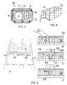
- FIG. 6 schematically illustrates an embodiment of a production step when fabricating the carrier PCBs 5, 7, 9 in accordance with the present invention. It is an advantage of embodiments of the present invention that the production of the carrier PCBs may be integrated with standard machines used for producing PCBs.
- the Figure illustrates a sheet 61 of PCB on which the carrier PCBs 5, 7, 9 are packed.
- the carrier PCBs are made up of three sections, the side PCB 7 carrying the antenna, the top PCB 5 carrying the display 11 and the side PCB 9 carrying the battery 8. Each section is separated from each other by a cut 64. Two adjacent PCBs are attached to each other by means of wire bondings 62 bridging the cuts.
- the wire bondings function as hinges so that the two adjacent PCBs in the consumption meter may be placed with an angle to each other.
- the top PCB 5 is provided with a protrusion for supporting the width of the display, whereas the side PCB 9 carrying the battery is provided with a corresponding indentation.
- the wire bonds 62 may also function as a conductor path between adjacent PCBs, thereby enabling electrical contact between elements of adjacent PCBs, such as an electrical contact between the antenna 6 and the circuit 3 and the battery 8 and the circuit 3.
- the consumption meter is assembled in a process comprising a number of steps.
- the PCBs 5, 7, 9 are released from the PCB sheet 61, e.g. by means of stamping.
- the PCBs are mounted inside a first part of the casing.
- the casing may be filled with the embedding material in a liquid form, and closed by the second, or remaining, part of the casing, so that an entire unit is provided.
- the liquid embedding material hardens, either before or after the casing has been closed off.
- the embedding material may in liquid form be introduced into an at least partly closed casing through a hole in the casing.
- the embedding of the elements may be performed in low-pressure conditions to avoid air bubbles, or at least to diminish the number of air bubbles, or at least to limit the size of the air bubbles, in the embedding material.
- the embedding of the element may consequently be performed in a pressure of 1/5 atmosphere, 1/10 atmosphere or lower.
Landscapes
- Physics & Mathematics (AREA)
- Fluid Mechanics (AREA)
- General Physics & Mathematics (AREA)
- Electromagnetism (AREA)
- Measuring Volume Flow (AREA)
- Arrangements For Transmission Of Measured Signals (AREA)
Priority Applications (1)
| Application Number | Priority Date | Filing Date | Title |
|---|---|---|---|
| PL08103536T PL1983311T3 (pl) | 2007-04-17 | 2008-04-15 | Miernik zużycia z wbudowanymi komponentami |
Applications Claiming Priority (1)
| Application Number | Priority Date | Filing Date | Title |
|---|---|---|---|
| DKPA200700560 | 2007-04-17 |
Publications (3)
| Publication Number | Publication Date |
|---|---|
| EP1983311A2 true EP1983311A2 (de) | 2008-10-22 |
| EP1983311A3 EP1983311A3 (de) | 2012-04-11 |
| EP1983311B1 EP1983311B1 (de) | 2020-10-07 |
Family
ID=39672715
Family Applications (1)
| Application Number | Title | Priority Date | Filing Date |
|---|---|---|---|
| EP08103536.2A Active EP1983311B1 (de) | 2007-04-17 | 2008-04-15 | Verbrauchsmesser mit eingebetteten Komponenten |
Country Status (5)
| Country | Link |
|---|---|
| EP (1) | EP1983311B1 (de) |
| DE (1) | DE08103536T1 (de) |
| DK (1) | DK1983311T3 (de) |
| LT (1) | LT1983311T (de) |
| PL (1) | PL1983311T3 (de) |
Cited By (12)
| Publication number | Priority date | Publication date | Assignee | Title |
|---|---|---|---|---|
| DE202008014171U1 (de) * | 2008-10-24 | 2010-03-25 | Körner, Hans-Holger | Durchflussmengenmesseinrichtung |
| WO2010112029A1 (en) * | 2009-04-02 | 2010-10-07 | Kamstrup A/S | Flow meter unit with water-tight casing |
| EP2278281A1 (de) | 2009-07-03 | 2011-01-26 | Kamstrup A/S | Durchflussmesser mit einem im Gehäuse eingerasteten Umlekspiegelhalter |
| WO2011127934A1 (en) | 2010-04-12 | 2011-10-20 | Miitors Aps | Ultrasonic consumption meter with locking mechanism |
| US8489342B2 (en) | 2011-03-18 | 2013-07-16 | Soneter, LLC | Methods and apparatus for fluid flow measurement |
| US8806957B2 (en) | 2009-12-15 | 2014-08-19 | Kamstrup A/S | Ultrasonic flow meter housing formed by a monolithic polymer structure |
| US8928137B2 (en) | 2013-05-15 | 2015-01-06 | Kamstrup A/S | Flow meter with ultrasound transducer directly connected to and fixed to measurement circuit board |
| WO2015081958A1 (en) * | 2013-12-03 | 2015-06-11 | Miitors Aps | Consumption meter comprising a foldable printed circuit board assembly |
| CN105222840A (zh) * | 2015-09-16 | 2016-01-06 | 中国电建集团贵阳勘测设计研究院有限公司 | 一种水利水电工程下泄生态流量实时监测系统及其方法 |
| US9557201B2 (en) | 2012-08-22 | 2017-01-31 | Apator Mitors Aps | Ultrasonic flow meter with a connection arrangement including elastic connectors arranged within an insulating support arrangement |
| US9903745B2 (en) | 2013-09-05 | 2018-02-27 | Apator Miitors Aps | Ultrasonic flow meter having ultrasonic reflectors including at least 50% by weight of copper and the signals including at least eight pulses |
| USRE47048E1 (en) | 2009-04-02 | 2018-09-18 | Kamstrup A/S | Flow meter with ultrasound transducer directly connected to and fixed to measurement circuit board |
Citations (2)
| Publication number | Priority date | Publication date | Assignee | Title |
|---|---|---|---|---|
| WO2000073743A2 (en) | 1999-05-28 | 2000-12-07 | Fusion Meters Limited | Utility meter |
| WO2007008692A2 (en) | 2005-07-08 | 2007-01-18 | Entegris, Inc. | Chemically inert flow controller with non-contaminating body |
Family Cites Families (5)
| Publication number | Priority date | Publication date | Assignee | Title |
|---|---|---|---|---|
| US5184064A (en) * | 1991-03-25 | 1993-02-02 | Stewart & Stevenson Services, Inc. | Encapsulated meter with optical programmer |
| JP2004156954A (ja) * | 2002-11-05 | 2004-06-03 | Yamamoto Takahiro | 電子計量スプーン |
| US6954144B1 (en) * | 2003-05-30 | 2005-10-11 | Amco Automated Systems, Inc. | Water pit transmitter assembly |
| DE102004052497A1 (de) * | 2004-10-28 | 2006-05-24 | Endress + Hauser Flowtec Ag | Gehäuse mit einem Anzeige- und/oder Bedienelement |
| GB2429061B (en) * | 2005-08-13 | 2009-04-22 | Flownetix Ltd | A method of construction for a low cost plastic ultrasonic water meter |
-
2008
- 2008-04-15 PL PL08103536T patent/PL1983311T3/pl unknown
- 2008-04-15 EP EP08103536.2A patent/EP1983311B1/de active Active
- 2008-04-15 DE DE08103536T patent/DE08103536T1/de active Pending
- 2008-04-15 DK DK08103536.2T patent/DK1983311T3/da active
- 2008-04-15 LT LTEP08103536.2T patent/LT1983311T/lt unknown
Patent Citations (2)
| Publication number | Priority date | Publication date | Assignee | Title |
|---|---|---|---|---|
| WO2000073743A2 (en) | 1999-05-28 | 2000-12-07 | Fusion Meters Limited | Utility meter |
| WO2007008692A2 (en) | 2005-07-08 | 2007-01-18 | Entegris, Inc. | Chemically inert flow controller with non-contaminating body |
Cited By (28)
| Publication number | Priority date | Publication date | Assignee | Title |
|---|---|---|---|---|
| DE202008014171U1 (de) * | 2008-10-24 | 2010-03-25 | Körner, Hans-Holger | Durchflussmengenmesseinrichtung |
| US9335192B2 (en) | 2009-04-02 | 2016-05-10 | Kamstrup A/S | Ultrasonic flow meter unit having a membrane and a top part forming a water-tight casing for the transducers and the circuit board |
| WO2010112029A1 (en) * | 2009-04-02 | 2010-10-07 | Kamstrup A/S | Flow meter unit with water-tight casing |
| USRE47048E1 (en) | 2009-04-02 | 2018-09-18 | Kamstrup A/S | Flow meter with ultrasound transducer directly connected to and fixed to measurement circuit board |
| CN102369418A (zh) * | 2009-04-02 | 2012-03-07 | 卡姆鲁普股份有限公司 | 具有水密壳体的流量计单元 |
| US9658090B2 (en) | 2009-04-02 | 2017-05-23 | Kamstrup A/S | Ultrasonic flow meter unit having a fixing mechanism to fix the water-tight casing including a membrane to a housing including a measuring tube |
| CN102369418B (zh) * | 2009-04-02 | 2014-09-17 | 卡姆鲁普股份有限公司 | 具有水密壳体的流量计单元 |
| EP2278281A1 (de) | 2009-07-03 | 2011-01-26 | Kamstrup A/S | Durchflussmesser mit einem im Gehäuse eingerasteten Umlekspiegelhalter |
| US8806957B2 (en) | 2009-12-15 | 2014-08-19 | Kamstrup A/S | Ultrasonic flow meter housing formed by a monolithic polymer structure |
| US9494452B2 (en) | 2010-04-12 | 2016-11-15 | Apator Miitors Aps | Ultrasonic consumption meter with locking mechanism |
| US9726528B2 (en) | 2010-04-12 | 2017-08-08 | Apator Miitors Aps | Ultrasonic consumption meter with locking mechanism |
| EP3734235A1 (de) | 2010-04-12 | 2020-11-04 | Apator Miitors ApS | Ultraschallverbrauchsmesser |
| US10215603B2 (en) | 2010-04-12 | 2019-02-26 | Apator Miitors Aps | Ultrasonic consumption meter with locking mechanism |
| WO2011127934A1 (en) | 2010-04-12 | 2011-10-20 | Miitors Aps | Ultrasonic consumption meter with locking mechanism |
| US8893559B2 (en) | 2010-04-12 | 2014-11-25 | Miitors Aps | Ultrasonic consumption meter with locking mechanism |
| US9933291B2 (en) | 2010-04-12 | 2018-04-03 | Apator Miitors Aps | Ultrasonic consumption meter with locking mechanism |
| US8489342B2 (en) | 2011-03-18 | 2013-07-16 | Soneter, LLC | Methods and apparatus for fluid flow measurement |
| US9874466B2 (en) | 2011-03-18 | 2018-01-23 | Reliance Worldwide Corporation | Methods and apparatus for ultrasonic fluid flow measurement and fluid flow data analysis |
| US9410833B1 (en) | 2011-03-18 | 2016-08-09 | Soneter, Inc. | Methods and apparatus for fluid flow measurement |
| US9568347B2 (en) | 2012-08-22 | 2017-02-14 | Apator Miitors Aps | Ultrasonic flow meter including a meter housing insert having transducer recesses with slanted bottom walls |
| US9557201B2 (en) | 2012-08-22 | 2017-01-31 | Apator Mitors Aps | Ultrasonic flow meter with a connection arrangement including elastic connectors arranged within an insulating support arrangement |
| US10359305B2 (en) | 2012-08-22 | 2019-07-23 | Apator Miitors Aps | Ultrasonic flow meter with a connection arrangement including elastic connectors arranged within an insulating support arrangement |
| US10488238B2 (en) | 2012-08-22 | 2019-11-26 | Apator Miitors Aps | Ultrasonic flow meter including a meter housing insert having transducer recesses with slanted bottom walls |
| US8928137B2 (en) | 2013-05-15 | 2015-01-06 | Kamstrup A/S | Flow meter with ultrasound transducer directly connected to and fixed to measurement circuit board |
| US9903745B2 (en) | 2013-09-05 | 2018-02-27 | Apator Miitors Aps | Ultrasonic flow meter having ultrasonic reflectors including at least 50% by weight of copper and the signals including at least eight pulses |
| WO2015081958A1 (en) * | 2013-12-03 | 2015-06-11 | Miitors Aps | Consumption meter comprising a foldable printed circuit board assembly |
| EP3667259A1 (de) * | 2013-12-03 | 2020-06-17 | Apator Miitors ApS | Verbrauchsmessgerät mit faltbarer leiterplattenanordnung und verfahren zur herstellung eines solchen verbrauchsmessgeräts |
| CN105222840A (zh) * | 2015-09-16 | 2016-01-06 | 中国电建集团贵阳勘测设计研究院有限公司 | 一种水利水电工程下泄生态流量实时监测系统及其方法 |
Also Published As
| Publication number | Publication date |
|---|---|
| DE08103536T1 (de) | 2009-04-16 |
| PL1983311T3 (pl) | 2021-06-28 |
| DK1983311T3 (da) | 2021-01-11 |
| EP1983311B1 (de) | 2020-10-07 |
| LT1983311T (lt) | 2021-01-11 |
| EP1983311A3 (de) | 2012-04-11 |
Similar Documents
| Publication | Publication Date | Title |
|---|---|---|
| EP1983311B1 (de) | Verbrauchsmesser mit eingebetteten Komponenten | |
| CN103900628B (zh) | 传感器系统和用于传感器系统的遮盖装置 | |
| US20170314978A1 (en) | Ultrasonic Consumption Meter With Locking Mechanism | |
| EP2181354B1 (de) | Verfahren zur herstellung und versiegelung eines flexiblen pixel-elements | |
| US20080220549A1 (en) | Sealed light emitting diode assemblies including annular gaskets and methods of making same | |
| CN106066305A (zh) | 包括光发射器单元和检测器单元的光声气体传感器模块 | |
| CN108511538A (zh) | 光电模块 | |
| KR20130040796A (ko) | 전자부품을 인쇄회로기판에 집적하는 방법, 및 그 안에 집적된 전자부품을 포함하는 인쇄회로기판 | |
| US11166363B2 (en) | Electrical node, method for manufacturing electrical node and multilayer structure comprising electrical node | |
| CN106601727B (zh) | 包模接近度传感器及相关联的方法 | |
| EP1711737A1 (de) | Abgedichtete gehäuseeinheit für beleuchtungssystem | |
| CN104421715B (zh) | 照明装置及对应方法 | |
| TW200520308A (en) | Portable object comprising a wristband provided with electrical connection means through the case, electrical contact flange for said object, and mounting method for said flange | |
| TW200735081A (en) | Function element mounting module, manufacturing method thereof, and resin sealing board and substrate-structured unit for resin sealing used by the same | |
| US8973437B2 (en) | Condensate sensing device | |
| KR20210049109A (ko) | 전기 노드, 전기 노드 제조 방법, 전기 노드 스트립 또는 시트, 노드를 포함하는 다층 구조 | |
| CN110366853A (zh) | 麦克风和测试麦克风的方法 | |
| CN103098248B (zh) | 用于制造光电子半导体器件的方法 | |
| CN209693277U (zh) | 一种电路板密封模组、红外检测模组及设备 | |
| CN109886224B (zh) | 显示模组、显示装置及其制造方法 | |
| CN206115923U (zh) | 一种具有漏电监测功能的广告灯 | |
| WO2011120770A1 (en) | Led module and manufacturing method thereof | |
| JP3807430B2 (ja) | 赤外線データ通信モジュールの製造方法 | |
| KR20100020918A (ko) | 밀봉 장치 및 그 제조 방법 | |
| CN108093564B (zh) | 电路板及其制作方法和电子设备 |
Legal Events
| Date | Code | Title | Description |
|---|---|---|---|
| PUAI | Public reference made under article 153(3) epc to a published international application that has entered the european phase |
Free format text: ORIGINAL CODE: 0009012 |
|
| AK | Designated contracting states |
Kind code of ref document: A2 Designated state(s): AT BE BG CH CY CZ DE DK EE ES FI FR GB GR HR HU IE IS IT LI LT LU LV MC MT NL NO PL PT RO SE SI SK TR |
|
| AX | Request for extension of the european patent |
Extension state: AL BA MK RS |
|
| DET | De: translation of patent claims | ||
| PUAL | Search report despatched |
Free format text: ORIGINAL CODE: 0009013 |
|
| AK | Designated contracting states |
Kind code of ref document: A3 Designated state(s): AT BE BG CH CY CZ DE DK EE ES FI FR GB GR HR HU IE IS IT LI LT LU LV MC MT NL NO PL PT RO SE SI SK TR |
|
| AX | Request for extension of the european patent |
Extension state: AL BA MK RS |
|
| RIC1 | Information provided on ipc code assigned before grant |
Ipc: G01F 15/00 20060101ALI20120302BHEP Ipc: G01F 15/14 20060101ALI20120302BHEP Ipc: G01F 1/66 20060101AFI20120302BHEP |
|
| 17P | Request for examination filed |
Effective date: 20121005 |
|
| RIN1 | Information on inventor provided before grant (corrected) |
Inventor name: DRACHMANN, JENS |
|
| AKX | Designation fees paid |
Designated state(s): AT BE BG CH CY CZ DE DK EE ES FI FR GB GR HR HU IE IS IT LI LT LU LV MC MT NL NO PL PT RO SE SI SK TR |
|
| 17Q | First examination report despatched |
Effective date: 20160607 |
|
| STAA | Information on the status of an ep patent application or granted ep patent |
Free format text: STATUS: EXAMINATION IS IN PROGRESS |
|
| GRAP | Despatch of communication of intention to grant a patent |
Free format text: ORIGINAL CODE: EPIDOSNIGR1 |
|
| STAA | Information on the status of an ep patent application or granted ep patent |
Free format text: STATUS: GRANT OF PATENT IS INTENDED |
|
| INTG | Intention to grant announced |
Effective date: 20200430 |
|
| GRAS | Grant fee paid |
Free format text: ORIGINAL CODE: EPIDOSNIGR3 |
|
| GRAA | (expected) grant |
Free format text: ORIGINAL CODE: 0009210 |
|
| STAA | Information on the status of an ep patent application or granted ep patent |
Free format text: STATUS: THE PATENT HAS BEEN GRANTED |
|
| REG | Reference to a national code |
Ref country code: DE Ref legal event code: R081 Ref document number: 602008063330 Country of ref document: DE Owner name: KAMSTRUP A/S, DK Free format text: FORMER OWNER: KAMSTRUP A/S, SKANDERBORG, DK |
|
| AK | Designated contracting states |
Kind code of ref document: B1 Designated state(s): AT BE BG CH CY CZ DE DK EE ES FI FR GB GR HR HU IE IS IT LI LT LU LV MC MT NL NO PL PT RO SE SI SK TR |
|
| REG | Reference to a national code |
Ref country code: GB Ref legal event code: FG4D |
|
| REG | Reference to a national code |
Ref country code: AT Ref legal event code: REF Ref document number: 1321645 Country of ref document: AT Kind code of ref document: T Effective date: 20201015 Ref country code: CH Ref legal event code: EP |
|
| REG | Reference to a national code |
Ref country code: DE Ref legal event code: R096 Ref document number: 602008063330 Country of ref document: DE |
|
| REG | Reference to a national code |
Ref country code: IE Ref legal event code: FG4D |
|
| REG | Reference to a national code |
Ref country code: FI Ref legal event code: FGE |
|
| REG | Reference to a national code |
Ref country code: SE Ref legal event code: TRGR |
|
| REG | Reference to a national code |
Ref country code: DK Ref legal event code: T3 Effective date: 20210108 Ref country code: NO Ref legal event code: T2 Effective date: 20201007 |
|
| REG | Reference to a national code |
Ref country code: NL Ref legal event code: MP Effective date: 20201007 |
|
| REG | Reference to a national code |
Ref country code: AT Ref legal event code: MK05 Ref document number: 1321645 Country of ref document: AT Kind code of ref document: T Effective date: 20201007 |
|
| PG25 | Lapsed in a contracting state [announced via postgrant information from national office to epo] |
Ref country code: PT Free format text: LAPSE BECAUSE OF FAILURE TO SUBMIT A TRANSLATION OF THE DESCRIPTION OR TO PAY THE FEE WITHIN THE PRESCRIBED TIME-LIMIT Effective date: 20210208 Ref country code: NL Free format text: LAPSE BECAUSE OF FAILURE TO SUBMIT A TRANSLATION OF THE DESCRIPTION OR TO PAY THE FEE WITHIN THE PRESCRIBED TIME-LIMIT Effective date: 20201007 Ref country code: GR Free format text: LAPSE BECAUSE OF FAILURE TO SUBMIT A TRANSLATION OF THE DESCRIPTION OR TO PAY THE FEE WITHIN THE PRESCRIBED TIME-LIMIT Effective date: 20210108 |
|
| PG25 | Lapsed in a contracting state [announced via postgrant information from national office to epo] |
Ref country code: ES Free format text: LAPSE BECAUSE OF FAILURE TO SUBMIT A TRANSLATION OF THE DESCRIPTION OR TO PAY THE FEE WITHIN THE PRESCRIBED TIME-LIMIT Effective date: 20201007 Ref country code: IS Free format text: LAPSE BECAUSE OF FAILURE TO SUBMIT A TRANSLATION OF THE DESCRIPTION OR TO PAY THE FEE WITHIN THE PRESCRIBED TIME-LIMIT Effective date: 20210207 Ref country code: BG Free format text: LAPSE BECAUSE OF FAILURE TO SUBMIT A TRANSLATION OF THE DESCRIPTION OR TO PAY THE FEE WITHIN THE PRESCRIBED TIME-LIMIT Effective date: 20210107 Ref country code: AT Free format text: LAPSE BECAUSE OF FAILURE TO SUBMIT A TRANSLATION OF THE DESCRIPTION OR TO PAY THE FEE WITHIN THE PRESCRIBED TIME-LIMIT Effective date: 20201007 Ref country code: LV Free format text: LAPSE BECAUSE OF FAILURE TO SUBMIT A TRANSLATION OF THE DESCRIPTION OR TO PAY THE FEE WITHIN THE PRESCRIBED TIME-LIMIT Effective date: 20201007 |
|
| PG25 | Lapsed in a contracting state [announced via postgrant information from national office to epo] |
Ref country code: HR Free format text: LAPSE BECAUSE OF FAILURE TO SUBMIT A TRANSLATION OF THE DESCRIPTION OR TO PAY THE FEE WITHIN THE PRESCRIBED TIME-LIMIT Effective date: 20201007 |
|
| REG | Reference to a national code |
Ref country code: DE Ref legal event code: R097 Ref document number: 602008063330 Country of ref document: DE |
|
| PG25 | Lapsed in a contracting state [announced via postgrant information from national office to epo] |
Ref country code: EE Free format text: LAPSE BECAUSE OF FAILURE TO SUBMIT A TRANSLATION OF THE DESCRIPTION OR TO PAY THE FEE WITHIN THE PRESCRIBED TIME-LIMIT Effective date: 20201007 Ref country code: CZ Free format text: LAPSE BECAUSE OF FAILURE TO SUBMIT A TRANSLATION OF THE DESCRIPTION OR TO PAY THE FEE WITHIN THE PRESCRIBED TIME-LIMIT Effective date: 20201007 Ref country code: SK Free format text: LAPSE BECAUSE OF FAILURE TO SUBMIT A TRANSLATION OF THE DESCRIPTION OR TO PAY THE FEE WITHIN THE PRESCRIBED TIME-LIMIT Effective date: 20201007 Ref country code: RO Free format text: LAPSE BECAUSE OF FAILURE TO SUBMIT A TRANSLATION OF THE DESCRIPTION OR TO PAY THE FEE WITHIN THE PRESCRIBED TIME-LIMIT Effective date: 20201007 |
|
| PLBE | No opposition filed within time limit |
Free format text: ORIGINAL CODE: 0009261 |
|
| STAA | Information on the status of an ep patent application or granted ep patent |
Free format text: STATUS: NO OPPOSITION FILED WITHIN TIME LIMIT |
|
| 26N | No opposition filed |
Effective date: 20210708 |
|
| PG25 | Lapsed in a contracting state [announced via postgrant information from national office to epo] |
Ref country code: IT Free format text: LAPSE BECAUSE OF FAILURE TO SUBMIT A TRANSLATION OF THE DESCRIPTION OR TO PAY THE FEE WITHIN THE PRESCRIBED TIME-LIMIT Effective date: 20201007 |
|
| PG25 | Lapsed in a contracting state [announced via postgrant information from national office to epo] |
Ref country code: SI Free format text: LAPSE BECAUSE OF FAILURE TO SUBMIT A TRANSLATION OF THE DESCRIPTION OR TO PAY THE FEE WITHIN THE PRESCRIBED TIME-LIMIT Effective date: 20201007 Ref country code: MC Free format text: LAPSE BECAUSE OF FAILURE TO SUBMIT A TRANSLATION OF THE DESCRIPTION OR TO PAY THE FEE WITHIN THE PRESCRIBED TIME-LIMIT Effective date: 20201007 |
|
| GBPC | Gb: european patent ceased through non-payment of renewal fee |
Effective date: 20210415 |
|
| PG25 | Lapsed in a contracting state [announced via postgrant information from national office to epo] |
Ref country code: LU Free format text: LAPSE BECAUSE OF NON-PAYMENT OF DUE FEES Effective date: 20210415 |
|
| REG | Reference to a national code |
Ref country code: BE Ref legal event code: MM Effective date: 20210430 |
|
| PG25 | Lapsed in a contracting state [announced via postgrant information from national office to epo] |
Ref country code: LI Free format text: LAPSE BECAUSE OF NON-PAYMENT OF DUE FEES Effective date: 20210430 Ref country code: CH Free format text: LAPSE BECAUSE OF NON-PAYMENT OF DUE FEES Effective date: 20210430 Ref country code: GB Free format text: LAPSE BECAUSE OF NON-PAYMENT OF DUE FEES Effective date: 20210415 |
|
| PG25 | Lapsed in a contracting state [announced via postgrant information from national office to epo] |
Ref country code: IE Free format text: LAPSE BECAUSE OF NON-PAYMENT OF DUE FEES Effective date: 20210415 |
|
| PG25 | Lapsed in a contracting state [announced via postgrant information from national office to epo] |
Ref country code: IS Free format text: LAPSE BECAUSE OF FAILURE TO SUBMIT A TRANSLATION OF THE DESCRIPTION OR TO PAY THE FEE WITHIN THE PRESCRIBED TIME-LIMIT Effective date: 20210207 |
|
| PG25 | Lapsed in a contracting state [announced via postgrant information from national office to epo] |
Ref country code: BE Free format text: LAPSE BECAUSE OF NON-PAYMENT OF DUE FEES Effective date: 20210430 |
|
| PG25 | Lapsed in a contracting state [announced via postgrant information from national office to epo] |
Ref country code: HU Free format text: LAPSE BECAUSE OF FAILURE TO SUBMIT A TRANSLATION OF THE DESCRIPTION OR TO PAY THE FEE WITHIN THE PRESCRIBED TIME-LIMIT; INVALID AB INITIO Effective date: 20080415 Ref country code: CY Free format text: LAPSE BECAUSE OF FAILURE TO SUBMIT A TRANSLATION OF THE DESCRIPTION OR TO PAY THE FEE WITHIN THE PRESCRIBED TIME-LIMIT Effective date: 20201007 |
|
| P01 | Opt-out of the competence of the unified patent court (upc) registered |
Effective date: 20230516 |
|
| PGFP | Annual fee paid to national office [announced via postgrant information from national office to epo] |
Ref country code: NO Payment date: 20230421 Year of fee payment: 16 Ref country code: FR Payment date: 20230420 Year of fee payment: 16 Ref country code: DK Payment date: 20230421 Year of fee payment: 16 Ref country code: DE Payment date: 20230420 Year of fee payment: 16 |
|
| PGFP | Annual fee paid to national office [announced via postgrant information from national office to epo] |
Ref country code: SE Payment date: 20230420 Year of fee payment: 16 Ref country code: PL Payment date: 20230412 Year of fee payment: 16 Ref country code: FI Payment date: 20230419 Year of fee payment: 16 |
|
| PGFP | Annual fee paid to national office [announced via postgrant information from national office to epo] |
Ref country code: LT Payment date: 20240327 Year of fee payment: 17 |