EP1982950A1 - Bremssystem für Aufzüge - Google Patents
Bremssystem für Aufzüge Download PDFInfo
- Publication number
- EP1982950A1 EP1982950A1 EP07381034A EP07381034A EP1982950A1 EP 1982950 A1 EP1982950 A1 EP 1982950A1 EP 07381034 A EP07381034 A EP 07381034A EP 07381034 A EP07381034 A EP 07381034A EP 1982950 A1 EP1982950 A1 EP 1982950A1
- Authority
- EP
- European Patent Office
- Prior art keywords
- pulley
- brake
- braking system
- lifts
- complementary
- Prior art date
- Legal status (The legal status is an assumption and is not a legal conclusion. Google has not performed a legal analysis and makes no representation as to the accuracy of the status listed.)
- Withdrawn
Links
- 230000000295 complement effect Effects 0.000 claims abstract description 16
- 239000000725 suspension Substances 0.000 claims description 4
- 230000000903 blocking effect Effects 0.000 description 2
- 230000000694 effects Effects 0.000 description 2
- 230000001105 regulatory effect Effects 0.000 description 2
- 230000006978 adaptation Effects 0.000 description 1
- 230000005540 biological transmission Effects 0.000 description 1
- 230000003993 interaction Effects 0.000 description 1
- 239000000463 material Substances 0.000 description 1
Images


Classifications
-
- B—PERFORMING OPERATIONS; TRANSPORTING
- B66—HOISTING; LIFTING; HAULING
- B66D—CAPSTANS; WINCHES; TACKLES, e.g. PULLEY BLOCKS; HOISTS
- B66D5/00—Braking or detent devices characterised by application to lifting or hoisting gear, e.g. for controlling the lowering of loads
- B66D5/02—Crane, lift hoist, or winch brakes operating on drums, barrels, or ropes
- B66D5/06—Crane, lift hoist, or winch brakes operating on drums, barrels, or ropes with radial effect
- B66D5/08—Crane, lift hoist, or winch brakes operating on drums, barrels, or ropes with radial effect embodying blocks or shoes
Definitions
- the object of the present invention is a braking system for lifts and elevation systems in general where the braking system is of the transversal type and situated in the extension of the axis of the drum or braking cone.
- the present braking system is characterised by the fact that it makes use of the space in one of the sides of the suspension pulley, using it to increase the braking force generated by the springs through a system of levers.
- the braking system may be applied both on the free surface of the pulley and by means of a brake drum rigidly attached to the pulley axis.
- the present invention is characterised by the increased braking force due to the transmission of the force by means of articulated arms which act as a lever.
- Braking systems used for lifts are based on various systems such as disc shoes or brakes of the drum type where the shoes and arms are on the same plane as the drum.
- the braking force is directly applied without there being any means which would enable the force generated for braking to be increased by the means of application used, which would result in a reduction of the braking force required.
- the object of the present invention is to develop a braking system with transversal application which may be applied on the possible free surface of the pulley as well as on the brake drum, which implies a reduction in the force which needs to be generated in order to obtain the braking torque, as well as making use of the space on one side of the pulley.
- the braking system which is the object of the invention makes use of the space on one side of the pulley and uses it to increase the braking force generated by the springs through a system of levers. On one end of the lever there is an electromagnetic coil which releases the brake.
- the braking system of a pulley for a lift or elevation system in general may either be applied on part of the free surface of the suspension pulley or by means of a brake drum rigidly attached to the pulley axis.
- the braking system comprises brake shoes fitted on an articulated arm which acts as a lever.
- the articulated arm is articulated on one of its ends on an axis and the other end is activated by a pre-stressed spring. Due to the tension of the spring, the lever tightens the brake shoe against the brake drum, preventing rotation of the drum, if there is one. In turn, the blocking of the drum rotation prevents the rotation of the pulley.
- an electromagnetic coil acts on the end of the lever in the opposite direction to the force of the springs.
- the coil acts through the effect of an electric current, this pushes the lever with a force greater than that exercised on the springs, transmitting movement to the brake shoes, so that these separate from the drum.
- the mechanical system is duplicated, two levers are used, two springs and two brake shoes in order to comply with the regulatory requirements for lifts.
- the braking force may be applied on part of the free surface of the elevation pulley or either on the brake drum.
- the brake shoes should be provided with a geometric form which is complementary to the surface on which they act, so that the contact surface between the shoe and the braking surface is as extensive as possible.
- the geometry which both the braking surface of either the pulley or the brake drum, like the shoes themselves, may be varied, with the only requirement being that both geometries should be complementary so that the braking surface or friction is optimum.
- a possible embodiment would be that the brake drum or pulleys were to be provided with a perimeter "V" shaped groove while the brake shoe would have a "V” shaped transversal section which could be coupled on the previous groove.
- Figure 1 shows the pulley (1) in which on part of the external surface there is a free surface (2) on which transversally arranged brake shoes (3) act.
- the brake shoes (3) are fitted on an articulated arm (4).
- Each articulated arm (4) functions as a lever.
- One end of each arm (4) is articulated on its respective axis (5) and the other end is activated by a pre-stressed spring (6).
- One end of each of the springs (6) rests on the base (8) and the other end of the springs (6) pulls a mobile part (7) associated with each spring (6).
- each spring (6) is transmitted through the mobile part (7) to the associated articulated arm (4), the articulated arm (4) tightens the brake shoe (3) against the free surface (2) part of the pulley or against a brake drum (11) ( figures 10 and 11 ), and due to the force of friction between the brake shoe and the free surface (2) or the drum (11),0 rotation of the pulley (1) or the drum (11) is prevented.
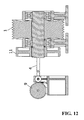
- an electromagnetic coil (9) which acts on one of the ends of the two articulated arms (4)in the opposite direction of the force of the springs (6).
- the coil (9) acts through the effect of an electric current, this pushes the levers (4) by means of push screws (10) joined to each of the articulated arms (4) with a force greater than and contrary to that exercised by the springs (6), transmitting the opening movement to the brake shoes (3) causing them to separate either from the free surface part (2) of the pulley (1) or the drum (11).
- the drum (11) is able to rotate freely and the support pulley (1).
- the mechanical system is duplicated, two levers are used, two springs and two brake shoes in order to comply with the regulatory requirements for lifts.
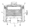
- Figures 2 , 3 and 4 show the elements described above in order to provide details of the relation and interaction between the various elements of the braking system.
- Figure 5 shows a section of the pulley together with the braking system, which shows how the shoes (3) and the free surface (2) of the pulley (1) remain in contact throughout their surface indicating a complementary geometry which in this case is smooth.
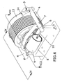
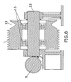
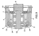
- Figures 6 , 7 , 8 and 9 show a form of alternative embodiment to the geometry of the free surface of the pulley (2) and the geometry of the brake shoes (3) where now the free surface (2) of the pulley _(1) shows a "V" shaped groove (13) into which a shoe (4) fits having a part of the external free surface of the pulley which should have a "V” shaped geometry complementary to the "V” shaped groove (13) so that surface contact is optimum, as may be seen in figure 9 .
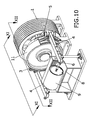
- Figure 10 shows a perspective representation of a pulley together with an associated braking system where the braking force is applied on a brake drum (11) which is rigidly joined to the pulley axis (12).
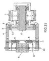
- Figures 11 and 12 show the sections obtained by cutting the unit of figure 10 through planes XI-XI and XII-XII respectively.
- the surface of the brake drum (11) and that of the shoes (3) should be complementary, in this case smooth, so that they contact throughout their surface, which encourages the braking action for which purpose both geometries that of the external surface of the brake drum and the section of the brake shoe, should be complementary.
- a form of alternative embodiment in respect of the geometries which may be presented by the brake drum surface and the brake shoe surface should be in a "V" shape, so that the brake drum would present a groove whereas the brake shoes would have complementary "V" shaped sections.
Landscapes
- Engineering & Computer Science (AREA)
- Mechanical Engineering (AREA)
- Braking Arrangements (AREA)
Priority Applications (1)
| Application Number | Priority Date | Filing Date | Title |
|---|---|---|---|
| EP07381034A EP1982950A1 (de) | 2007-04-17 | 2007-04-17 | Bremssystem für Aufzüge |
Applications Claiming Priority (1)
| Application Number | Priority Date | Filing Date | Title |
|---|---|---|---|
| EP07381034A EP1982950A1 (de) | 2007-04-17 | 2007-04-17 | Bremssystem für Aufzüge |
Publications (1)
| Publication Number | Publication Date |
|---|---|
| EP1982950A1 true EP1982950A1 (de) | 2008-10-22 |
Family
ID=38480098
Family Applications (1)
| Application Number | Title | Priority Date | Filing Date |
|---|---|---|---|
| EP07381034A Withdrawn EP1982950A1 (de) | 2007-04-17 | 2007-04-17 | Bremssystem für Aufzüge |
Country Status (1)
| Country | Link |
|---|---|
| EP (1) | EP1982950A1 (de) |
Cited By (1)
| Publication number | Priority date | Publication date | Assignee | Title |
|---|---|---|---|---|
| EP3326953A1 (de) * | 2016-11-18 | 2018-05-30 | Otis Elevator Company | Nachrüsten einer aufzugsmaschine mit primär- und sekundärbremsung |
Citations (4)
| Publication number | Priority date | Publication date | Assignee | Title |
|---|---|---|---|---|
| US4875558A (en) * | 1989-03-16 | 1989-10-24 | Otis Elevator Company | Safety brake for escalators |
| US6146303A (en) * | 1994-10-10 | 2000-11-14 | Wittur Ag | Drive unit for a hoist |
| EP1298084A2 (de) * | 2001-09-28 | 2003-04-02 | Kabushiki Kaisha Meidensha | Aufzugsantrieb |
| DE10246588A1 (de) * | 2002-10-05 | 2004-04-22 | System Antriebstechnik Dresden Gmbh | Nothalte-Bremseinrichtung für Aufzugsmaschinen |
-
2007
- 2007-04-17 EP EP07381034A patent/EP1982950A1/de not_active Withdrawn
Patent Citations (4)
| Publication number | Priority date | Publication date | Assignee | Title |
|---|---|---|---|---|
| US4875558A (en) * | 1989-03-16 | 1989-10-24 | Otis Elevator Company | Safety brake for escalators |
| US6146303A (en) * | 1994-10-10 | 2000-11-14 | Wittur Ag | Drive unit for a hoist |
| EP1298084A2 (de) * | 2001-09-28 | 2003-04-02 | Kabushiki Kaisha Meidensha | Aufzugsantrieb |
| DE10246588A1 (de) * | 2002-10-05 | 2004-04-22 | System Antriebstechnik Dresden Gmbh | Nothalte-Bremseinrichtung für Aufzugsmaschinen |
Cited By (4)
| Publication number | Priority date | Publication date | Assignee | Title |
|---|---|---|---|---|
| EP3326953A1 (de) * | 2016-11-18 | 2018-05-30 | Otis Elevator Company | Nachrüsten einer aufzugsmaschine mit primär- und sekundärbremsung |
| US10618775B2 (en) | 2016-11-18 | 2020-04-14 | Otis Elevator Company | Retrofitting an elevator machine with primary and secondary braking |
| US11377323B2 (en) | 2016-11-18 | 2022-07-05 | Otis Elevator Company | Retrofitting an elevator machine with primary and secondary braking |
| EP4234474A3 (de) * | 2016-11-18 | 2023-09-20 | Otis Elevator Company | Nachrüsten einer aufzugsmaschine mit primär- und sekundärbremsung |
Similar Documents
| Publication | Publication Date | Title |
|---|---|---|
| EP0416760A1 (de) | Aufbau einer Bremse | |
| JP3551382B2 (ja) | 機械的駆動ドラムブレーキ | |
| EP0046432A3 (de) | Scheibenbremse | |
| MY108647A (en) | Safety anchorages for controlling pay-out of a safety line | |
| US8469159B2 (en) | Brake assembly | |
| KR20060045942A (ko) | 차량의 연동 브레이크 장치 | |
| JPH0233892B2 (de) | ||
| US4193481A (en) | Drag free sliding caliper disc brake bushing | |
| EP0015178B1 (de) | Trommelbremsen-Vorrichtung | |
| US3664469A (en) | Mechanically-operated disc-brake | |
| CN103717276B (zh) | 用于滚轴轮滑鞋、滑板或类似物的制动装置 | |
| CA1111356A (en) | Pin slider disc brake | |
| JPS5926810B2 (ja) | 摺動キヤリパ−式デイスクブレ−キ | |
| EP0063513A1 (de) | Trommelbremse mit doppelter Wirkungsweise | |
| EP1982950A1 (de) | Bremssystem für Aufzüge | |
| US6286631B1 (en) | Actuating lever for a wheelbarrow brake | |
| US20040149524A1 (en) | Cable brake at a speed limiter for lifts | |
| EP0800015A3 (de) | Trommelbremse mit nur einer Bremsbacken-Spreizvorrichtung | |
| EP0299929B1 (de) | Federnde Vorrichtung zur Verbindung von zwei Konstruktionselementen | |
| US3708040A (en) | Disk brake with servo action | |
| US3315769A (en) | Self-energizing caliper type disc brake | |
| TWI901312B (zh) | 煞車機構及嬰兒載具 | |
| KR920006218A (ko) | 엘레베이터 | |
| SE434986B (sv) | Bromskraftoverforande bultstyrning for en skivbroms med flytande bygel | |
| BR0211133A (pt) | Freio a disco |
Legal Events
| Date | Code | Title | Description |
|---|---|---|---|
| PUAI | Public reference made under article 153(3) epc to a published international application that has entered the european phase |
Free format text: ORIGINAL CODE: 0009012 |
|
| AK | Designated contracting states |
Kind code of ref document: A1 Designated state(s): AT BE BG CH CY CZ DE DK EE ES FI FR GB GR HU IE IS IT LI LT LU LV MC MT NL PL PT RO SE SI SK TR |
|
| AX | Request for extension of the european patent |
Extension state: AL BA HR MK RS |
|
| AKX | Designation fees paid | ||
| REG | Reference to a national code |
Ref country code: DE Ref legal event code: 8566 |
|
| STAA | Information on the status of an ep patent application or granted ep patent |
Free format text: STATUS: THE APPLICATION IS DEEMED TO BE WITHDRAWN |
|
| 18D | Application deemed to be withdrawn |
Effective date: 20090423 |