EP1982870A1 - Occupant leg part restraint apparatus - Google Patents
Occupant leg part restraint apparatus Download PDFInfo
- Publication number
- EP1982870A1 EP1982870A1 EP07706798A EP07706798A EP1982870A1 EP 1982870 A1 EP1982870 A1 EP 1982870A1 EP 07706798 A EP07706798 A EP 07706798A EP 07706798 A EP07706798 A EP 07706798A EP 1982870 A1 EP1982870 A1 EP 1982870A1
- Authority
- EP
- European Patent Office
- Prior art keywords
- airbag
- cover cloth
- cover
- steering column
- key
- Prior art date
- Legal status (The legal status is an assumption and is not a legal conclusion. Google has not performed a legal analysis and makes no representation as to the accuracy of the status listed.)
- Granted
Links
- 239000004744 fabric Substances 0.000 claims abstract description 47
- 210000002414 leg Anatomy 0.000 description 17
- 230000037431 insertion Effects 0.000 description 2
- 238000003780 insertion Methods 0.000 description 2
- 210000003127 knee Anatomy 0.000 description 2
- 230000002093 peripheral effect Effects 0.000 description 2
- 239000000463 material Substances 0.000 description 1
- 230000000452 restraining effect Effects 0.000 description 1
- 238000009423 ventilation Methods 0.000 description 1
Images


Classifications
-
- B—PERFORMING OPERATIONS; TRANSPORTING
- B60—VEHICLES IN GENERAL
- B60R—VEHICLES, VEHICLE FITTINGS, OR VEHICLE PARTS, NOT OTHERWISE PROVIDED FOR
- B60R21/00—Arrangements or fittings on vehicles for protecting or preventing injuries to occupants or pedestrians in case of accidents or other traffic risks
- B60R21/02—Occupant safety arrangements or fittings, e.g. crash pads
- B60R21/16—Inflatable occupant restraints or confinements designed to inflate upon impact or impending impact, e.g. air bags
- B60R21/23—Inflatable members
- B60R21/231—Inflatable members characterised by their shape, construction or spatial configuration
-
- B—PERFORMING OPERATIONS; TRANSPORTING
- B60—VEHICLES IN GENERAL
- B60R—VEHICLES, VEHICLE FITTINGS, OR VEHICLE PARTS, NOT OTHERWISE PROVIDED FOR
- B60R21/00—Arrangements or fittings on vehicles for protecting or preventing injuries to occupants or pedestrians in case of accidents or other traffic risks
- B60R21/02—Occupant safety arrangements or fittings, e.g. crash pads
- B60R21/16—Inflatable occupant restraints or confinements designed to inflate upon impact or impending impact, e.g. air bags
- B60R21/20—Arrangements for storing inflatable members in their non-use or deflated condition; Arrangement or mounting of air bag modules or components
- B60R21/205—Arrangements for storing inflatable members in their non-use or deflated condition; Arrangement or mounting of air bag modules or components in dashboards
- B60R21/206—Arrangements for storing inflatable members in their non-use or deflated condition; Arrangement or mounting of air bag modules or components in dashboards in the lower part of dashboards, e.g. for protecting the knees
-
- B—PERFORMING OPERATIONS; TRANSPORTING
- B60—VEHICLES IN GENERAL
- B60R—VEHICLES, VEHICLE FITTINGS, OR VEHICLE PARTS, NOT OTHERWISE PROVIDED FOR
- B60R21/00—Arrangements or fittings on vehicles for protecting or preventing injuries to occupants or pedestrians in case of accidents or other traffic risks
- B60R21/02—Occupant safety arrangements or fittings, e.g. crash pads
- B60R21/16—Inflatable occupant restraints or confinements designed to inflate upon impact or impending impact, e.g. air bags
- B60R21/23—Inflatable members
- B60R21/231—Inflatable members characterised by their shape, construction or spatial configuration
- B60R21/2334—Expansion control features
- B60R21/2338—Tethers
-
- B—PERFORMING OPERATIONS; TRANSPORTING
- B60—VEHICLES IN GENERAL
- B60R—VEHICLES, VEHICLE FITTINGS, OR VEHICLE PARTS, NOT OTHERWISE PROVIDED FOR
- B60R21/00—Arrangements or fittings on vehicles for protecting or preventing injuries to occupants or pedestrians in case of accidents or other traffic risks
- B60R21/02—Occupant safety arrangements or fittings, e.g. crash pads
- B60R21/16—Inflatable occupant restraints or confinements designed to inflate upon impact or impending impact, e.g. air bags
- B60R21/23—Inflatable members
- B60R21/231—Inflatable members characterised by their shape, construction or spatial configuration
- B60R2021/23169—Inflatable members characterised by their shape, construction or spatial configuration specially adapted for knee protection
-
- B—PERFORMING OPERATIONS; TRANSPORTING
- B60—VEHICLES IN GENERAL
- B60R—VEHICLES, VEHICLE FITTINGS, OR VEHICLE PARTS, NOT OTHERWISE PROVIDED FOR
- B60R21/00—Arrangements or fittings on vehicles for protecting or preventing injuries to occupants or pedestrians in case of accidents or other traffic risks
- B60R21/02—Occupant safety arrangements or fittings, e.g. crash pads
- B60R21/16—Inflatable occupant restraints or confinements designed to inflate upon impact or impending impact, e.g. air bags
- B60R21/23—Inflatable members
- B60R21/231—Inflatable members characterised by their shape, construction or spatial configuration
- B60R21/2334—Expansion control features
- B60R21/2338—Tethers
- B60R2021/23382—Internal tether means
Definitions
- the present invention relates to a passenger leg portion constraining apparatus for constraining a leg portion of a passenger upon collision of a vehicle and, more specifically, to a leg portion constraining apparatus for a passenger on a driver's seat.
- a knee airbag apparatus for constraining a leg portion of a passenger upon collision is installed below a steering column of a vehicle.
- a gas generator is activated to inject gas, and the injected gas is supplied to an airbag to inflate and deploy the airbag in a space between the interior panel and lower legs of the passenger so that the leg portion of the passenger is constrained.
- Japanese Unexamined Patent Application Publication No. 2004-345530 there is described that the airbag is provided with a cover cloth in order to prevent direct interference of a key inserted into a key cylinder in a steering column cover or other keys attached thereto with the knee airbag.
- Patent Document 1 Japanese Unexamined Patent Application Publication No. 2004-345530
- the passenger leg portion constraining apparatus is a passenger leg portion constraining apparatus having an airbag which is arranged below the steering column and is capable of inflating upward along a space near a lower surface of a steering column cover, including a cover cloth provided on the airbag so as to protrude upward from an upper end portion of the airbag when the airbag is inflated and be interposed between the airbag and a key apparatus of a vehicle, the cover cloth being mounted at the proximal end side thereof to a surface on the side of an instrument panel of the airbag, characterized in that a vertical midsection of the cover cloth is connected to an upper portion of the airbag.
- the cover cloth protrudes upward from an upper end portion of an airbag and is interposed between the airbag and a key apparatus when the airbag is inflated. Accordingly, direct interference between the airbag and attached keys is prevented.
- the cover cloth since a vertical midsection of a cover cloth is connected to an upper portion of the airbag, the cover cloth moves quickly by being pulled by the upper portion of the airbag, and protrudes upward.
- the cover cloth When the protruding portion protruded from the vertical midsection of a side of the cover cloth is connected to the upper portion of the airbag, the cover cloth can extend easily from the proximal end thereof along a steering column cover.
- Fig. 1a is a front view of an airbag for a passenger leg portion constraining apparatus according to an embodiment of the present invention
- Fig. 1b and Fig. 1c are cross-sectional views taken along the line Ib-Ib and Ic-Ic in Fig. 1a respectively
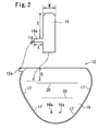
- Fig. 2 is an exploded view of the airbag and a cover cloth
- Fig. 3 is a side-view of a space in front of a driver's seat of a vehicle showing a state in which the airbag is inflated.
- the lateral direction corresponds to the widthwise direction of a vehicle body.
- a steering column protrudes from an instrument panel 1 in front of the driver's seat of the vehicle, and the steering column is surrounded by a steering column cover 2.
- a steering wheel 3 is secured to a steering shaft (not shown) projecting from the steering column.
- a key apparatus (key cylinder) 4 is provided on the right side portion (the right side portion when viewed from the driver's seat) of the steering column cover 2.
- a key 5 inserted into the key apparatus 4 has an attached key (in the present invention, the attached key also includes a key different from a key for a vehicle and accessories other than the key such as a key holder) 6 in a state of being suspended therefrom.
- the attached key 6 is suspended downward with respect to the lower surface of the steering column cover 2 in the normal state (in a state in which it is not pushed upward by a cover cloth 14 described later).
- a passenger leg portion constraining apparatus 10 is installed below the steering column cover 2.
- the passenger leg portion constraining apparatus 10 includes a case 11 of a container shape having an opening (reference numeral is not given) on the front surface (the surface on the passenger's side), a lid (not shown) which covers the opening, an airbag 12 connected to the interior of the case 11, and a gas inflator 13 for inflating the airbag 12.
- the case 11 is arranged in an airbag inflation opening (not shown) provided in an area of the instrument panel 1 below the steering column cover 2.
- the airbag 12 is folded and is stored in the case 11, and the lid (not shown) is mounted to the opening on the front surface of the case 11 so as to cover the folded body of the airbag 12.
- the lid is configured to open by being pressed by the airbag 12 when the airbag 12 is inflated to release the airbag inflation opening.
- the airbag 12 is inflated by gas from the gas generator 13 and, as shown in Fig. 3 , is inflated toward the front surface of the instrument panel 1 via the airbag inflating opening, and then is deployed upward from below so as to extend from an area of the instrument panel 1 below the steering column cover 2 along the lower surface of the steering column cover 2.
- the airbag 12 has a shape increasing in lateral width (the widthwise direction of the vehicle body) from the lower side to the upper side as shown in Fig. 1a , and the lateral width of the upper portion of the airbag 12 is larger than the lateral width of the steering column cover 2.
- the laterally intermediate portion of the upper portion of the airbag 12 opposes the lower surface of the steering column cover 2, and the left side portion and the right side portion are expanded sideward from with respect to the left side portion and the right side portion of the steering column cover 2.
- left and right correspond to the left and right when viewing the airbag 12 from the passenger side, and in Fig. 1a and Fig. 2 , which illustrate views from the side opposite from the passenger, the left and right are inverted. Hereinafter, the left and right are used on the basis of the view from the passenger.
- the airbag 12 is provided with the cover cloth 14 which is protruded from the upper end portion of the airbag 12 upward to interpose between the airbag 12 and the key apparatus 4 when the airbag 12 is inflated.
- the cover cloth 14 is arranged on the right side portion of the upper portion of the airbag 12.
- the airbag 12 includes a front surface 15 on the passenger side and a rear surface 16 on the instrument panel 1 side.
- the airbag 12 is manufactured by two-folding a panel, which constitutes the front surface 15 on one half thereof and the rear surface 16 on the other half thereof, and stitching aligned peripheral edges of the front surface 15 and the rear surface 16.
- Reference numeral 17 designates a seam of the stitch.
- the cover cloth 14 is composed of a band-shaped panel provided separately from an outer shell of the airbag 12, that is, the panel which constitutes the front surface 15 and the rear surface 16.
- the cover cloth 14 is arranged on the rear surface 16 side with the direction of extension thereof oriented in the vertical direction, and the lower end side, that is, the proximal end side is attached by stitching to the upper portion of the right side portion of the rear surface 16.
- Reference numeral 14s designates a seam of the stitch.
- the cover cloth 14 is provided with a protruding portion 14a which protrudes rightward from a vertically midsection of the right side thereof.
- the protruding portion 14a is formed into a band shape and is protruded rightward from the right side of the cover cloth 14 at a substantially right angle.
- a lug 12a for connecting the protruding portion is protruded from the right end side of the upper side of the airbag 12.
- the distal end side of the protruding portion 14a is attached to the lug 12a by stitching, the vertically midsection of the cover cloth 14 is connected to the upper end portion of the airbag 12 via the protruding portion 14a and the lug 12a.
- the reference numeral 14s' designates a seam stitching the protruding portion 14a and the lug 12a.
- the lower end side of the cover cloth 14 is preferably attached to the rear surface 16 by stitching at a position apart from the upper side (the seam 17 along the upper side) of the rear surface 16 downwardly in a state in which the airbag 12 is deployed flatly.
- a distance D from the upper side of the rear surface 16 to the stitching portion is preferably from 30 to 200 mm, more specifically, from 100 to 150 mm.
- a distance S ( Fig. 2 ) from the upper end portion of the cover cloth 14 to a connecting position of the cover cloth 14 to the upper end portion of the airbag (the position to arrange the protruding portion 14a) is preferably from 50 to 120 mm, more specifically, from 150 to 200 m.
- a lateral width W of the cover cloth 14 is preferably from 30 to 300 mm, more specifically, from 120 to 200 mm.
- a sideward protruding length L ( Fig. 2 ) of the protruding portion 14a from the side of the cover cloth 14 is preferably from 10 to 200 mm, more specifically, from 30 to 150 mm.
- the vertical width T ( Fig. 2 ) of the protruding portion 14a is preferably from 10 to 100 mm, more specifically, from 20 to 50 mm.
- the material of the cover cloth 14 is not specifically limited.
- a tether 19 for restraining the thickness of inflation of the airbag 12 by connecting the front surface 15 and the rear surface 16 is provided in the interior of the airbag 12.
- Reference numeral 20 designates a seam which attaches both end portions of the tether 19 in the direction of the thickness of the airbag respectively to the front surface 15 and the rear surface 16.
- the tether 19 extends continuously in the lateral direction, and a plurality of tethers are provided in multiple levels (two levels in this embodiment). The both lateral end portions of the respective tethers 19 are apart from the left and right sides of the airbag 12, and an air ventilation space is formed therebetween.
- the gas inflator 13 is arranged in the interior of the airbag 12.
- a stud bolt 13a is protruded from the gas inflator 13 or from a holder (not shown) which holds the same.
- the stud bolt 13a is inserted through an insertion hole 16a provided in the portion near the lower end portion of the rear surface 16 and an insertion hole (not shown) provided on the rear surface of the case 11 respectively, and a nut 13b is tightened on the stud bolt 13a, so that the gas inflator 13 and the portion near the lower end of the rear surface 16 are fixed to the case 11.
- the airbag 12 is folded and stored in the interior of the case 11, and the lid is mounted to the case 11, so that the passenger leg portion constraining apparatus 10 is configured.
- the gas inflator 13 When the vehicle having the passenger leg portion constraining apparatus 10 in this configuration collides, the gas inflator 13 is activated to inject gas, and the airbag 12 starts to be inflated.
- the airbag 12 is firstly inflated toward the front surface of the instrument panel 1 via an airbag inflation opening 7 while pushing and opening the lid, and then is deployed upwardly along the front surface of the instrument panel 1.
- the cover cloth 14 protrudes upward from the upper end portion of the right side portion of the airbag 12, and is interposed between the airbag 12 and the key apparatus 4. Accordingly, direct interference between the airbag 12 and the key 5 or the attached key 6 is prevented.
- the cover cloth 14 since the vertically midsection of the cover cloth 14 is connected to the upper end portion of the airbag 12 via the protruding portion 14a, the cover cloth 14 is moved quickly by being pulled by the upper end portion of the airbag 12 and is protruded upward.
- the protruding portion may be configured integrally with the cover cloth, and may be configured separately and attached to the cover cloth later.
- the protruding portion may be of a shape other than the band shape.
- the protruding portion may be provided at a midsection of the left side of the cover cloth.
- the cover cloth may be connected to the upper end portion of the airbag by connecting means other than the protruding portion.
- the configuration of the peripheral members of the steering and the airbag may be laterally inverted from the embodiment shown above.
Landscapes
- Engineering & Computer Science (AREA)
- Mechanical Engineering (AREA)
- Air Bags (AREA)
- Steering Controls (AREA)
Abstract
Description
- The present invention relates to a passenger leg portion constraining apparatus for constraining a leg portion of a passenger upon collision of a vehicle and, more specifically, to a leg portion constraining apparatus for a passenger on a driver's seat.
- There is a case in which a knee airbag apparatus for constraining a leg portion of a passenger upon collision is installed below a steering column of a vehicle. Upon collision of the vehicle, a gas generator is activated to inject gas, and the injected gas is supplied to an airbag to inflate and deploy the airbag in a space between the interior panel and lower legs of the passenger so that the leg portion of the passenger is constrained.
- In Japanese Unexamined Patent Application Publication No.
2004-345530
Patent Document 1 Japanese Unexamined Patent Application Publication No.2004-345530 - It is an object of the present invention to provide a passenger leg portion constraining apparatus including a cover cloth for preventing interference between an airbag to be inflated and deployed below a steering column (steering column cover) and other keys attached thereto, in which the cover cloth is protruded quickly upward from the airbag.
- The passenger leg portion constraining apparatus according to the present invention is a passenger leg portion constraining apparatus having an airbag which is arranged below the steering column and is capable of inflating upward along a space near a lower surface of a steering column cover, including a cover cloth provided on the airbag so as to protrude upward from an upper end portion of the airbag when the airbag is inflated and be interposed between the airbag and a key apparatus of a vehicle, the cover cloth being mounted at the proximal end side thereof to a surface on the side of an instrument panel of the airbag, characterized in that a vertical midsection of the cover cloth is connected to an upper portion of the airbag.
- A configuration in which a protruding portion protruding from the vertical midsection of a side of the cover cloth sideward is provided and the protruding portion is connected to the upper portion of the airbag is also applicable.
-
- [
Fig. 1] Fig. 1a is a front view of an airbag of a passenger leg portion constraining apparatus according to an embodiment, andFigs. 1b and 1c are cross-sectional views inFig. 1a taken along the lines Ib-Ib and Ic-Ic respectively. - [
Fig. 2] Fig. 2 is an exploded view of the airbag and a cover cloth. - [
Fig. 3 ] is a side view of a space in front of a driver's sheet in a vehicle showing a state in which the airbag is inflated. - According to the passenger leg portion constraining apparatus of the present invention, the cover cloth protrudes upward from an upper end portion of an airbag and is interposed between the airbag and a key apparatus when the airbag is inflated. Accordingly, direct interference between the airbag and attached keys is prevented.
- According to the present invention, since a vertical midsection of a cover cloth is connected to an upper portion of the airbag, the cover cloth moves quickly by being pulled by the upper portion of the airbag, and protrudes upward.
- When the protruding portion protruded from the vertical midsection of a side of the cover cloth is connected to the upper portion of the airbag, the cover cloth can extend easily from the proximal end thereof along a steering column cover.
- Referring now to the drawings, an embodiment of the present invention will be described.
-
Fig. 1a is a front view of an airbag for a passenger leg portion constraining apparatus according to an embodiment of the present invention,Fig. 1b and Fig. 1c are cross-sectional views taken along the line Ib-Ib and Ic-Ic inFig. 1a respectively,Fig. 2 is an exploded view of the airbag and a cover cloth andFig. 3 is a side-view of a space in front of a driver's seat of a vehicle showing a state in which the airbag is inflated. In the description shown below, the lateral direction corresponds to the widthwise direction of a vehicle body. - As shown in
Fig. 3 , a steering column (not shown) protrudes from an instrument panel 1 in front of the driver's seat of the vehicle, and the steering column is surrounded by asteering column cover 2. A steering wheel 3 is secured to a steering shaft (not shown) projecting from the steering column. - In this embodiment, a key apparatus (key cylinder) 4 is provided on the right side portion (the right side portion when viewed from the driver's seat) of the
steering column cover 2. Akey 5 inserted into the key apparatus 4 has an attached key (in the present invention, the attached key also includes a key different from a key for a vehicle and accessories other than the key such as a key holder) 6 in a state of being suspended therefrom. The attached key 6 is suspended downward with respect to the lower surface of thesteering column cover 2 in the normal state (in a state in which it is not pushed upward by acover cloth 14 described later). - A passenger leg
portion constraining apparatus 10 is installed below thesteering column cover 2. - The passenger leg
portion constraining apparatus 10 includes acase 11 of a container shape having an opening (reference numeral is not given) on the front surface (the surface on the passenger's side), a lid (not shown) which covers the opening, anairbag 12 connected to the interior of thecase 11, and agas inflator 13 for inflating theairbag 12. - The
case 11 is arranged in an airbag inflation opening (not shown) provided in an area of the instrument panel 1 below thesteering column cover 2. In the normal state, theairbag 12 is folded and is stored in thecase 11, and the lid (not shown) is mounted to the opening on the front surface of thecase 11 so as to cover the folded body of theairbag 12. The lid is configured to open by being pressed by theairbag 12 when theairbag 12 is inflated to release the airbag inflation opening. - The
airbag 12 is inflated by gas from thegas generator 13 and, as shown inFig. 3 , is inflated toward the front surface of the instrument panel 1 via the airbag inflating opening, and then is deployed upward from below so as to extend from an area of the instrument panel 1 below thesteering column cover 2 along the lower surface of thesteering column cover 2. - In this embodiment, the
airbag 12 has a shape increasing in lateral width (the widthwise direction of the vehicle body) from the lower side to the upper side as shown inFig. 1a , and the lateral width of the upper portion of theairbag 12 is larger than the lateral width of thesteering column cover 2. In a state in which theairbag 12 is inflated along the lower surface of thesteering column cover 2, the laterally intermediate portion of the upper portion of theairbag 12 opposes the lower surface of thesteering column cover 2, and the left side portion and the right side portion are expanded sideward from with respect to the left side portion and the right side portion of thesteering column cover 2. - The terms "left" and "right" correspond to the left and right when viewing the
airbag 12 from the passenger side, and inFig. 1a andFig. 2 , which illustrate views from the side opposite from the passenger, the left and right are inverted. Hereinafter, the left and right are used on the basis of the view from the passenger. - The
airbag 12 is provided with thecover cloth 14 which is protruded from the upper end portion of theairbag 12 upward to interpose between theairbag 12 and the key apparatus 4 when theairbag 12 is inflated. In this embodiment, thecover cloth 14 is arranged on the right side portion of the upper portion of theairbag 12. - In this embodiment, the
airbag 12 includes afront surface 15 on the passenger side and arear surface 16 on the instrument panel 1 side. In this embodiment, theairbag 12 is manufactured by two-folding a panel, which constitutes thefront surface 15 on one half thereof and therear surface 16 on the other half thereof, and stitching aligned peripheral edges of thefront surface 15 and therear surface 16.Reference numeral 17 designates a seam of the stitch. - As shown in
Fig. 2 , thecover cloth 14 is composed of a band-shaped panel provided separately from an outer shell of theairbag 12, that is, the panel which constitutes thefront surface 15 and therear surface 16. Thecover cloth 14 is arranged on therear surface 16 side with the direction of extension thereof oriented in the vertical direction, and the lower end side, that is, the proximal end side is attached by stitching to the upper portion of the right side portion of therear surface 16.Reference numeral 14s designates a seam of the stitch. - The
cover cloth 14 is provided with a protrudingportion 14a which protrudes rightward from a vertically midsection of the right side thereof. In this embodiment, theprotruding portion 14a is formed into a band shape and is protruded rightward from the right side of thecover cloth 14 at a substantially right angle. As shown inFig. 2 , alug 12a for connecting the protruding portion is protruded from the right end side of the upper side of theairbag 12. The distal end side of the protrudingportion 14a is attached to thelug 12a by stitching, the vertically midsection of thecover cloth 14 is connected to the upper end portion of theairbag 12 via theprotruding portion 14a and thelug 12a. Thereference numeral 14s' designates a seam stitching theprotruding portion 14a and thelug 12a. - As shown in
Fig. 2 , the lower end side of thecover cloth 14 is preferably attached to therear surface 16 by stitching at a position apart from the upper side (theseam 17 along the upper side) of therear surface 16 downwardly in a state in which theairbag 12 is deployed flatly. A distance D from the upper side of therear surface 16 to the stitching portion is preferably from 30 to 200 mm, more specifically, from 100 to 150 mm. - A distance S (
Fig. 2 ) from the upper end portion of thecover cloth 14 to a connecting position of thecover cloth 14 to the upper end portion of the airbag (the position to arrange the protrudingportion 14a) is preferably from 50 to 120 mm, more specifically, from 150 to 200 m. - A lateral width W of the
cover cloth 14 is preferably from 30 to 300 mm, more specifically, from 120 to 200 mm. - A sideward protruding length L (
Fig. 2 ) of the protrudingportion 14a from the side of thecover cloth 14 is preferably from 10 to 200 mm, more specifically, from 30 to 150 mm. The vertical width T (Fig. 2 ) of the protrudingportion 14a is preferably from 10 to 100 mm, more specifically, from 20 to 50 mm. - The material of the
cover cloth 14 is not specifically limited. - In this embodiment, as shown in
Fig. 1c , atether 19 for restraining the thickness of inflation of theairbag 12 by connecting thefront surface 15 and therear surface 16 is provided in the interior of theairbag 12.Reference numeral 20 designates a seam which attaches both end portions of thetether 19 in the direction of the thickness of the airbag respectively to thefront surface 15 and therear surface 16. In this embodiment, thetether 19 extends continuously in the lateral direction, and a plurality of tethers are provided in multiple levels (two levels in this embodiment). The both lateral end portions of therespective tethers 19 are apart from the left and right sides of theairbag 12, and an air ventilation space is formed therebetween. - The
gas inflator 13 is arranged in the interior of theairbag 12. Astud bolt 13a is protruded from thegas inflator 13 or from a holder (not shown) which holds the same. Thestud bolt 13a is inserted through aninsertion hole 16a provided in the portion near the lower end portion of therear surface 16 and an insertion hole (not shown) provided on the rear surface of thecase 11 respectively, and anut 13b is tightened on thestud bolt 13a, so that thegas inflator 13 and the portion near the lower end of therear surface 16 are fixed to thecase 11. - Subsequently, the
airbag 12 is folded and stored in the interior of thecase 11, and the lid is mounted to thecase 11, so that the passenger legportion constraining apparatus 10 is configured. - When the vehicle having the passenger leg
portion constraining apparatus 10 in this configuration collides, thegas inflator 13 is activated to inject gas, and theairbag 12 starts to be inflated. Theairbag 12 is firstly inflated toward the front surface of the instrument panel 1 via an airbag inflation opening 7 while pushing and opening the lid, and then is deployed upwardly along the front surface of the instrument panel 1. - In this case, as shown in
Fig. 3 , thecover cloth 14 protrudes upward from the upper end portion of the right side portion of theairbag 12, and is interposed between theairbag 12 and the key apparatus 4. Accordingly, direct interference between theairbag 12 and the key 5 or the attached key 6 is prevented. - According to the passenger leg
portion constraining apparatus 10, since the vertically midsection of thecover cloth 14 is connected to the upper end portion of theairbag 12 via the protrudingportion 14a, thecover cloth 14 is moved quickly by being pulled by the upper end portion of theairbag 12 and is protruded upward. - The embodiment shown above is only an example of the present invention, and the present invention is not limited to the configuration shown in the drawings.
- For example, the protruding portion may be configured integrally with the cover cloth, and may be configured separately and attached to the cover cloth later. The protruding portion may be of a shape other than the band shape. The protruding portion may be provided at a midsection of the left side of the cover cloth. The cover cloth may be connected to the upper end portion of the airbag by connecting means other than the protruding portion.
- The configuration of the peripheral members of the steering and the airbag may be laterally inverted from the embodiment shown above.
- The present application is based on Japanese Patent Application (Japanese Patent Application No.
2006-033498
Claims (7)
- A passenger leg portion constraining apparatus having an airbag which is arranged below a steering column and is capable of inflating upward along a space near the lower surface of a steering column cover, comprising:a cover cloth provided on the airbag so as to protrude upward from an upper end portion of the airbag when the airbag is inflated and be interposed between the airbag and a key apparatus of a vehicle,the cover cloth being mounted at the proximal end side thereof to a surface on the side of an instrument panel of the airbag,characterized in that a vertical midsection of the cover cloth is connected to an upper portion of the airbag.
- The passenger leg portion constraining apparatus according to Claim 1, comprising a protruding portion protruding from the vertical midsection of a side of the cover cloth sideward, characterized in that the protruding portion is connected to the upper portion of the airbag.
- The passenger leg portion constraining apparatus according to Claim 2, characterized in that the protruding portion is connected to the upper end portion of the airbag.
- The passenger leg portion constraining apparatus according to Claim 3, comprising a lug provided on the left end or the right end of the upper end of the airbag, characterized in that the protruding portion is connected to the lug.
- The passenger leg portion constraining apparatus according to Claim 2, characterized in that a distance (S) from the upper end of the cover cloth to the protruding portion is from 50 to 120 m.
- The passenger leg portion constraining apparatus according to Claim 1, characterized in that a lateral width (W) of the cover cloth is from 30 to 300 mm.
- The passenger leg portion constraining apparatus according to Claim 1, wherein a distance (D) from a connecting portion between the proximal end of the cover cloth and the airbag to the upper end of the airbag is from 30 to 200 mm.
Applications Claiming Priority (2)
| Application Number | Priority Date | Filing Date | Title |
|---|---|---|---|
| JP2006033498A JP4894283B2 (en) | 2006-02-10 | 2006-02-10 | Passenger leg restraining device |
| PCT/JP2007/050471 WO2007091404A1 (en) | 2006-02-10 | 2007-01-16 | Occupant leg part restraint apparatus |
Publications (3)
| Publication Number | Publication Date |
|---|---|
| EP1982870A1 true EP1982870A1 (en) | 2008-10-22 |
| EP1982870A4 EP1982870A4 (en) | 2009-04-29 |
| EP1982870B1 EP1982870B1 (en) | 2013-03-27 |
Family
ID=38345011
Family Applications (1)
| Application Number | Title | Priority Date | Filing Date |
|---|---|---|---|
| EP07706798A Ceased EP1982870B1 (en) | 2006-02-10 | 2007-01-16 | Vehicle with occupant leg part restraint apparatus |
Country Status (5)
| Country | Link |
|---|---|
| US (1) | US7845673B2 (en) |
| EP (1) | EP1982870B1 (en) |
| JP (1) | JP4894283B2 (en) |
| CN (1) | CN101346260B (en) |
| WO (1) | WO2007091404A1 (en) |
Families Citing this family (5)
| Publication number | Priority date | Publication date | Assignee | Title |
|---|---|---|---|---|
| JP2009190553A (en) * | 2008-02-14 | 2009-08-27 | Toyota Motor Corp | Knee airbag device with column |
| JP4877280B2 (en) * | 2008-06-09 | 2012-02-15 | 豊田合成株式会社 | Knee protection airbag |
| US8696019B2 (en) * | 2011-03-21 | 2014-04-15 | Tk Holdings Inc. | Knee airbag module |
| US8740247B1 (en) | 2012-12-27 | 2014-06-03 | Nissan North America, Inc. | Airbag assembly |
| KR102439460B1 (en) * | 2015-09-30 | 2022-09-02 | 현대모비스 주식회사 | knee airbag |
Family Cites Families (12)
| Publication number | Priority date | Publication date | Assignee | Title |
|---|---|---|---|---|
| JPH0769149A (en) | 1993-09-02 | 1995-03-14 | Takata Kk | Air bag device for assistant driver's seat |
| JP3948332B2 (en) * | 2002-04-15 | 2007-07-25 | タカタ株式会社 | Crew protection device |
| DE10360509B4 (en) * | 2002-12-27 | 2012-04-26 | Toyoda Gosei Co., Ltd. | Knee-protecting airbag device |
| JP4016842B2 (en) * | 2003-01-24 | 2007-12-05 | トヨタ自動車株式会社 | Vehicle occupant knee protection device |
| JP2004284416A (en) * | 2003-03-19 | 2004-10-14 | Toyoda Gosei Co Ltd | Airbag device for knee protection |
| JP4063712B2 (en) * | 2003-05-22 | 2008-03-19 | 豊田合成株式会社 | Air bag device for knee protection |
| JP2005225464A (en) * | 2004-01-14 | 2005-08-25 | Takata Corp | Leg-protection device for vehicle occupant |
| JP2005225463A (en) * | 2004-01-14 | 2005-08-25 | Takata Corp | Leg-protection device for vehicle occupant |
| US7377541B2 (en) * | 2004-01-14 | 2008-05-27 | Takata Corporation | Leg-protection device for vehicle occupant |
| JP4665669B2 (en) * | 2005-08-30 | 2011-04-06 | タカタ株式会社 | Passenger leg restraining device |
| JP4235222B2 (en) * | 2006-11-02 | 2009-03-11 | トヨタ自動車株式会社 | Knee airbag device with column |
| US20080116669A1 (en) * | 2006-11-14 | 2008-05-22 | Toyoda Gosei Co., Ltd. | Knee-protecting airbag device |
-
2006
- 2006-02-10 JP JP2006033498A patent/JP4894283B2/en not_active Expired - Fee Related
-
2007
- 2007-01-16 US US11/988,457 patent/US7845673B2/en not_active Expired - Fee Related
- 2007-01-16 CN CN2007800008745A patent/CN101346260B/en not_active Expired - Fee Related
- 2007-01-16 EP EP07706798A patent/EP1982870B1/en not_active Ceased
- 2007-01-16 WO PCT/JP2007/050471 patent/WO2007091404A1/en not_active Ceased
Non-Patent Citations (2)
| Title |
|---|
| No further relevant documents disclosed * |
| See also references of WO2007091404A1 * |
Also Published As
| Publication number | Publication date |
|---|---|
| US20100117341A1 (en) | 2010-05-13 |
| CN101346260B (en) | 2012-01-04 |
| EP1982870B1 (en) | 2013-03-27 |
| US7845673B2 (en) | 2010-12-07 |
| JP4894283B2 (en) | 2012-03-14 |
| EP1982870A4 (en) | 2009-04-29 |
| WO2007091404A1 (en) | 2007-08-16 |
| JP2007210498A (en) | 2007-08-23 |
| CN101346260A (en) | 2009-01-14 |
Similar Documents
| Publication | Publication Date | Title |
|---|---|---|
| US7549671B2 (en) | Knee-protecting airbag apparatus | |
| JP5163975B2 (en) | Airbag device | |
| JP4997753B2 (en) | Crew restraint system | |
| US7681908B2 (en) | Knee airbag device | |
| US6224088B1 (en) | Inflatable occupant protection device extending adjacent a windshield | |
| JP3321978B2 (en) | Airbag device | |
| EP2650178B1 (en) | Knee airbag with clamshell housing | |
| JP5366592B2 (en) | Air bag and air bag device | |
| WO2007083423A1 (en) | Seat device | |
| JP4446830B2 (en) | Airbag device | |
| JP4665669B2 (en) | Passenger leg restraining device | |
| EP1982870B1 (en) | Vehicle with occupant leg part restraint apparatus | |
| JP4235223B2 (en) | Knee airbag device for vehicle | |
| JP2006143044A (en) | Vehicle occupant leg protection device | |
| JP2007216733A (en) | Airbag device for vehicle | |
| JP2008114701A (en) | Knee airbag device with column | |
| JP4336250B2 (en) | Airbag device | |
| JP6609459B2 (en) | Leg airbag system | |
| JP2003267178A (en) | Airbag device for knee protection | |
| JP2007161203A (en) | Occupant restraining device | |
| JP5424947B2 (en) | Airbag | |
| KR20150022257A (en) | Air-bag apparatus for vehicles | |
| JP4747824B2 (en) | Crew restraint system | |
| JP2007176346A (en) | Occupant restraint system | |
| KR100835942B1 (en) | Mounting structure of air bag tether |
Legal Events
| Date | Code | Title | Description |
|---|---|---|---|
| PUAI | Public reference made under article 153(3) epc to a published international application that has entered the european phase |
Free format text: ORIGINAL CODE: 0009012 |
|
| 17P | Request for examination filed |
Effective date: 20080130 |
|
| AK | Designated contracting states |
Kind code of ref document: A1 Designated state(s): DE GB |
|
| RBV | Designated contracting states (corrected) |
Designated state(s): DE GB |
|
| A4 | Supplementary search report drawn up and despatched |
Effective date: 20090326 |
|
| 17Q | First examination report despatched |
Effective date: 20090721 |
|
| DAX | Request for extension of the european patent (deleted) | ||
| REG | Reference to a national code |
Ref country code: DE Ref legal event code: R079 Ref document number: 602007029310 Country of ref document: DE Free format text: PREVIOUS MAIN CLASS: B60R0021200000 Ipc: B60R0021231000 |
|
| GRAP | Despatch of communication of intention to grant a patent |
Free format text: ORIGINAL CODE: EPIDOSNIGR1 |
|
| RIC1 | Information provided on ipc code assigned before grant |
Ipc: B60R 21/2338 20110101ALI20121023BHEP Ipc: B60R 21/231 20110101AFI20121023BHEP Ipc: B60R 21/206 20110101ALI20121023BHEP |
|
| GRAS | Grant fee paid |
Free format text: ORIGINAL CODE: EPIDOSNIGR3 |
|
| GRAA | (expected) grant |
Free format text: ORIGINAL CODE: 0009210 |
|
| AK | Designated contracting states |
Kind code of ref document: B1 Designated state(s): DE GB |
|
| REG | Reference to a national code |
Ref country code: GB Ref legal event code: FG4D |
|
| REG | Reference to a national code |
Ref country code: DE Ref legal event code: R096 Ref document number: 602007029310 Country of ref document: DE Effective date: 20130523 |
|
| PLBE | No opposition filed within time limit |
Free format text: ORIGINAL CODE: 0009261 |
|
| STAA | Information on the status of an ep patent application or granted ep patent |
Free format text: STATUS: NO OPPOSITION FILED WITHIN TIME LIMIT |
|
| 26N | No opposition filed |
Effective date: 20140103 |
|
| REG | Reference to a national code |
Ref country code: DE Ref legal event code: R097 Ref document number: 602007029310 Country of ref document: DE Effective date: 20140103 |
|
| GBPC | Gb: european patent ceased through non-payment of renewal fee |
Effective date: 20140116 |
|
| PG25 | Lapsed in a contracting state [announced via postgrant information from national office to epo] |
Ref country code: GB Free format text: LAPSE BECAUSE OF NON-PAYMENT OF DUE FEES Effective date: 20140116 |
|
| REG | Reference to a national code |
Ref country code: DE Ref legal event code: R082 Ref document number: 602007029310 Country of ref document: DE Representative=s name: KRAUS & WEISERT PATENTANWAELTE PARTGMBB, DE Ref country code: DE Ref legal event code: R081 Ref document number: 602007029310 Country of ref document: DE Owner name: JOYSON SAFETY SYSTEMS JAPAN K.K., JP Free format text: FORMER OWNER: TAKATA CORPORATION, MINATO-KU, TOKYO, JP |
|
| PGFP | Annual fee paid to national office [announced via postgrant information from national office to epo] |
Ref country code: DE Payment date: 20200121 Year of fee payment: 14 |
|
| REG | Reference to a national code |
Ref country code: DE Ref legal event code: R119 Ref document number: 602007029310 Country of ref document: DE |
|
| PG25 | Lapsed in a contracting state [announced via postgrant information from national office to epo] |
Ref country code: DE Free format text: LAPSE BECAUSE OF NON-PAYMENT OF DUE FEES Effective date: 20210803 |