EP1982797A2 - Setzwerkzeug für einen Dämmstoffdübel - Google Patents
Setzwerkzeug für einen Dämmstoffdübel Download PDFInfo
- Publication number
- EP1982797A2 EP1982797A2 EP08103475A EP08103475A EP1982797A2 EP 1982797 A2 EP1982797 A2 EP 1982797A2 EP 08103475 A EP08103475 A EP 08103475A EP 08103475 A EP08103475 A EP 08103475A EP 1982797 A2 EP1982797 A2 EP 1982797A2
- Authority
- EP
- European Patent Office
- Prior art keywords
- drive shaft
- setting tool
- tool according
- stop plate
- insulation
- Prior art date
- Legal status (The legal status is an assumption and is not a legal conclusion. Google has not performed a legal analysis and makes no representation as to the accuracy of the status listed.)
- Granted
Links
Images

Classifications
-
- B—PERFORMING OPERATIONS; TRANSPORTING
- B25—HAND TOOLS; PORTABLE POWER-DRIVEN TOOLS; MANIPULATORS
- B25B—TOOLS OR BENCH DEVICES NOT OTHERWISE PROVIDED FOR, FOR FASTENING, CONNECTING, DISENGAGING, OR HOLDING
- B25B21/00—Portable power-driven screw or nut setting or loosening tools; Attachments for drilling apparatus serving the same purpose
- B25B21/002—Portable power-driven screw or nut setting or loosening tools; Attachments for drilling apparatus serving the same purpose for special purposes
-
- B—PERFORMING OPERATIONS; TRANSPORTING
- B25—HAND TOOLS; PORTABLE POWER-DRIVEN TOOLS; MANIPULATORS
- B25B—TOOLS OR BENCH DEVICES NOT OTHERWISE PROVIDED FOR, FOR FASTENING, CONNECTING, DISENGAGING, OR HOLDING
- B25B31/00—Hand tools for applying fasteners
-
- E—FIXED CONSTRUCTIONS
- E04—BUILDING
- E04D—ROOF COVERINGS; SKY-LIGHTS; GUTTERS; ROOF-WORKING TOOLS
- E04D15/00—Apparatus or tools for roof working
- E04D15/04—Apparatus or tools for roof working for roof coverings comprising slabs, sheets or flexible material
-
- E—FIXED CONSTRUCTIONS
- E04—BUILDING
- E04B—GENERAL BUILDING CONSTRUCTIONS; WALLS, e.g. PARTITIONS; ROOFS; FLOORS; CEILINGS; INSULATION OR OTHER PROTECTION OF BUILDINGS
- E04B1/00—Constructions in general; Structures which are not restricted either to walls, e.g. partitions, or floors or ceilings or roofs
- E04B1/62—Insulation or other protection; Elements or use of specified material therefor
- E04B1/74—Heat, sound or noise insulation, absorption, or reflection; Other building methods affording favourable thermal or acoustical conditions, e.g. accumulating of heat within walls
- E04B1/76—Heat, sound or noise insulation, absorption, or reflection; Other building methods affording favourable thermal or acoustical conditions, e.g. accumulating of heat within walls specifically with respect to heat only
- E04B1/762—Exterior insulation of exterior walls
- E04B1/7629—Details of the mechanical connection of the insulation to the wall
- E04B1/7633—Dowels with enlarged insulation retaining head
-
- E—FIXED CONSTRUCTIONS
- E04—BUILDING
- E04D—ROOF COVERINGS; SKY-LIGHTS; GUTTERS; ROOF-WORKING TOOLS
- E04D15/00—Apparatus or tools for roof working
- E04D15/04—Apparatus or tools for roof working for roof coverings comprising slabs, sheets or flexible material
- E04D2015/042—Fixing to the roof supporting structure
- E04D2015/047—Fixing to the roof supporting structure by screwing
Definitions
- the invention relates to a setting tool for anchoring with a fastener in the ground insulation dowels, comprising a first drive shaft having a longitudinal axis extending shaft with a first rotational driving means for the fastener at a first end and with a second rotary driving means for a setting tool on a second , the first end opposite the first end, and having a coaxial with the first drive shaft arranged second drive shaft having a hollow shaft with a third rotational drive means for the insulating dowel at a first end, as well as with an axially releasable coupling for transmitting a torque of the first drive shaft to the second drive shaft, which is arranged at a portion spaced from the first end of the second drive shaft.
- insulation dowels For the attachment of insulation boards so-called insulation dowels are used, which have a shaft with an anchoring portion at one end and a plate-shaped, other end. Through the insulation plate through a hole is created in the ground. Subsequently, the insulating dowel is introduced with its anchoring portion having the end ahead in the bore and anchored with a fastener, such as a spreader, underground. In the set state of the insulation plug, the plate-shaped end is located on the surface of the insulation board or this is sunk in the insulation board.
- the insulation holder has a shank with a conical end from which protrudes a fastening screw, and an insulation holder plate on the other end.
- the insulation holder plate has a recess on the circumference as a rotational drive.
- the setting tool comprises a first drive shaft, which is a having a longitudinal axis extending shaft with a cross recess for the fastening screw at a first end and with a hexagon for a screwdriver at a second end.
- a second drive shaft Coaxially to the first drive shaft, a second drive shaft is arranged, which has a hollow shaft and a stop plate projecting radially therefrom. On the stop plate, a spring-mounted carrier pin is provided, which engages for transmitting torque from the first drive shaft to the insulating material holder in the recess on the insulating holder plate. If the insulating holder plate comes into contact with the surface of the roofing sheet, the driving pin is pushed out of the recess on the insulating sheet holder, wherein the rotationally fixed connection between the first drive shaft and the insulation holder is interrupted. The Phillips drive continues to rotate until the mounting screw is fully threaded into the substructure.
- a clutch detachable by axial pressure is provided for transmitting a torque from the first drive shaft to the second drive shaft, which ensures a decoupling of the first from the second drive shaft.
- a disadvantage of the known solution according to the DE 197 54 356 A1 is that the force is applied eccentrically between the setting tool and the insulating material holder. At higher torques, this can lead to a twisting of the insulation holder plate or even damage to the insulation holder. Furthermore, with such a setting tool no insulation dowels can be set, the pressure plate should at least partially penetrate into the insulation material when setting.
- the setting tool has a first drive shaft and a coaxial with the first drive shaft arranged second drive shaft with a hollow shaft, which has a third rotational drive means for the insulating dowel at a first end. Further, an axially releasable coupling for transmitting a torque from the first drive shaft to the second drive shaft at a portion of the second drive shaft is provided, which is arranged spaced from the first end.
- the clutch comprises a cooperating with a radially circumferential first groove on the first drive shaft elastic ring and a polygonal receptacle, which cooperates for torque transmission from the first drive shaft to the second drive shaft with a polygonal thickening on the first drive shaft.
- a disadvantage of the known solution according to the US 5,255,485 is that the coupling between the first and the second drive shaft must be solved by a manual pressure in the setting direction. As a result, a uniform deep setting several insulation dowels is not guaranteed.
- the object of the invention is to provide a setting tool for an anchored with a fastener in the ground insulation dowel, which ensures a simple and uniform deep setting the insulation dowel, the pressure plate of the insulation anchor in the set state on the surface of the insulation material or penetrate into this can.
- a stop plate is mounted on the second drive shaft, whose axial distance to the first end of the second drive shaft via a positioning device can be preset.
- At least partially superior stop plate is fixed axially to the second drive shaft after the corresponding axial displacement, whereby the setting depth of the insulating anchor is determined in the insulating material.
- the introduction of force from the setting tool in the insulation dowel is done centrally. Tilting or twisting of the pressure plate when setting the insulation anchor is largely excluded.
- the insulating dowel has, for example, a spreading area which can be widened by an expansion screw as a fastening means.
- a rotational drive is provided, for. B. a recording in which the third rotary driving means, for. B. a matched to the recording outer polygon, at the first end of the second drive shaft for transmitting the torque from the second drive shaft engages the insulation dowel.
- the first rotational drive means for the fastener at the first end of the first drive shaft is, for example, a trained on the rotational drive of the fastener screwdriver bit or a receptacle for a polygonal bit having at the free end with the rotational drive of the fastener engageable, free end.
- the second rotational drive means for the fastener at the second end of the first drive shaft for example, a spigot, which in the tool holder of the setting tool, such as. As a screwdriver or a drill, can be inserted.
- an additional coupling is provided, which ensures an axial feed force to the setting tool at the beginning of the setting process.
- the additional coupling couples for torque transmission from the setting tool on the first drive shaft.
- the stop plate is mounted on the second drive shaft via a rotary bearing. Due to the freely rotatable mounting of the stop plate on the second drive shaft this does not rotate with a transmission of torque from the second drive shaft on the insulation dowel with the second drive shaft. Thus, between the Stop plate and the anchor plate of the insulation anchor excluded torque transmission.
- the positioning device forms the pivot bearing for the stop plate on the second drive shaft.
- the positioning device comprises a plurality of radially arranged locking grooves and a engageable in the locking grooves holding device, via which the stop plate is axially fixed to the second drive shaft.
- the locking grooves are provided for example on the lateral surface of the second drive shaft.
- a second drive shaft at least partially surrounding wall portion is provided on which the locking grooves are formed or arranged.
- the locking grooves are axially spaced from each other in a predetermined pattern.
- the locking grooves are arranged in a 5 mm or 1 cm or in corresponding country-specific unit spacing to each other.
- the holding device for the axial fixation of the stop plate comprises, for example, at least one spring-loaded ball or a clamping cone, which can be brought about a locking means with the locking grooves for axial fixation of the stop plate and out of engagement with the axial displaceability of the stop plate.
- This holding device can for example form the pivot bearing for the rotatable mounting of the stop plate on the second drive shaft.
- the locking grooves are formed radially circumferentially, which allows a simple axial adjustment of the stop plate without a prior alignment of the stop plate with respect to the axially spaced locking grooves.
- a pivot bearing is provided between the stop plate and the holding device.
- the holding device can be mounted rotationally fixed to the second drive shaft, whereby the stop plate is still easily rotatably mounted on the second drive shaft.
- the pivot bearing is designed for example as a ball bearing.
- the positioning device has at least one spacer element which is arranged between the stop plate and a stop on the second drive shaft. Due to the axial length of the at least one spacer element, the setting depth of the insulating anchor is determined relative to the surface of the insulating board.
- the at least one spacer element is, for example, a tubular one Element portion having a certain axial length, which is fixed to the stop plate or formed on this. Alternatively, the at least one spacer element is a separate part, which is provided loosely between the stop plate and the stop.
- the stop is formed at an end region at a second, the first end opposite end of the second drive shaft.
- the stop is formed by a radial projection of the second drive shaft superior housing portion of the coupling between the first and the second drive shaft.
- the at least one spacer element has predetermined separation points, which enable a simple adaptation of the at least one spacer element to the required or desired setting depth.
- the predetermined separation points are formed as arranged in a certain grid recesses along which the spacer element is cut to length, z. B. by cutting or canceling.
- the cut-to-length portions of the spacer may optionally be used to extend the cut or a new spacer in another application of the setting tool.
- the positioning device comprises a plurality of spacer elements which can be arranged axially one behind the other as required. For example, all spacers on the same axial length and are arranged according to the desired or required depth of the insulation plug in succession. Alternatively, the spacers have different lengths axial lengths and are combined, provided according to the desired or required setting depth of the insulation plug between the stop plate and the stop.
- the at least one spacer element is substantially hollow-cylindrical and has a longitudinal slot extending over the entire axial length of the spacer element.
- a spacer element with a corresponding elasticity is easily plugged onto the second drive shaft.
- the first drive shaft 22 has a shaft 23 extending along a longitudinal axis 31 with a screwdriver bit receptacle as the first rotational drive means 24 for the fastening means 16 at a first end 25 and with a plug-in end as a second rotary drive means 26 for an electric screwdriver as a setting tool device 8 at a second, the first End 25 opposite end 27 on.
- an additional clutch 28 is provided at the second end 27 at the second end 27, an additional clutch 28 is provided.
- the additional clutch 28 comprises a sleeve-shaped portion 51 which is coaxially guided over the second end 25 of the first drive shaft 22.
- cam lugs 29 are provided radially projecting from the first drive shaft 22, which can be brought into engagement with cam receivers 53 on the sleeve-shaped portion 51.
- a spring element 52 is provided, for. B. a coil spring which holds the additional clutch 28 in a disengaged position.
- the second drive shaft 32 is arranged coaxially with the first drive shaft 22 and has a hollow shaft 33 with an outer polygon as the third rotational drive means 34 for the insulating dowel 11 at a first end 35.
- an axially releasable coupling 38 for transmitting torque from the first drive shaft 22 to the second drive shaft 32 intended.
- the coupling 38 comprises a clamping ring 56 which has a control cam for blocking elements 57 in the form of balls.
- the blocking elements 57 engage in a control cam on the first drive shaft 22.
- the coupling 38 is surrounded by a housing 58 which projects beyond the radial projection of the second drive shaft 32. In the housing 58 is further on Spring element 59 is provided, for. Example, a coil spring which forces the clamping ring 56 in contact with the locking elements 57 and thus holds the clutch 38 in an engaged state.
- a stop plate 41 is freely rotatably mounted on the second drive shaft 32 via a pivot bearing. Its axial distance to the first end 35 of the second drive shaft 32 can be preset via a positioning device 46.
- the stop plate 41 is arranged for its positioning on the second drive shaft 32 with respect to the longitudinal axis 31 axially displaceable.
- the positioning device 46 comprises a plurality of radially arranged and radially encircling latching grooves 47 and an engageable in the latching grooves 47 holding means 43, by means of which the stop plate 41 on the second drive shaft 32 is axially fixed.
- a pivot bearing 42 is provided between the stop plate 41 and the holding device 43.
- the insulating anchor 11 is provided with the expansion screw as a fastening means 16 and is placed as a whole on the setting tool 21 and then inserted into the previously created by the to be fastened insulation board 7 into the ground 6 hole 9 (see Fig. 2A ).
- the insulating dowel 11 is inserted with the expansion screw into the wellbore 9 and then the setting tool 21 is coupled to the insulating dowel 11.
- the insulating dowel 11 has at one end a helical pressure plate 12 with a receptacle as a rotary driving 13, which is engageable with the third rotary driving means 34 at the first end 35 of the second drive shaft 32 for transmitting the torque from the second drive shaft 32 to the insulating dowel 11 ,
- the stop plate 41 has been displaced axially along the second drive shaft 32 in order to set the desired setting depth of the insulating dowel 11 and fixed axially to the second drive shaft 32 by means of the positioning device 46.
- the stop plate 41 abuts against the surface 10 of the insulating plate 7.
- the pressure on the clutch 38 between the second drive shaft 32 and the first drive shaft 22 increases the pressure on the clutch 38 between the second drive shaft 32 and the first drive shaft 22 so that it triggers and a transmission of torque from the first drive shaft 22 to the second drive shaft 32 and thus to the insulation dowel 11 interrupts.
- the first drive shaft 22 is further driven in rotation, so that the fastening means 16 can be driven further to widen the anchoring region 14 of the insulating anchor 11.
- the third rotational driving means 34 on the second drive shaft 32 advantageously has a conical design, so that when setting the insulating anchor 11, a frictional engagement or a clamping between the third rotary driving means 34 and the rotational drive 13 of the insulating anchor 11 takes place. Due to the easily releasable holding force between the setting tool 21 and the insulating dowel 11, the second drive shaft 32 is automatically brought into the front, engaged initial position when the setting tool 21 is pulled out after completion of the setting process (see Fig. 2C ).
- the second drive shaft 32 can be manually pushed forward again in the direction of the first end 25 of the first drive shaft 22 until the coupling 38 engages the first drive shaft 22 and the second drive shaft 32 again rotatably coupled with each other.
- the setting tool 21 is available for a renewed setting process of a further insulating dowel 11, which is set exactly and correctly deep as the previously set insulation dowel 11.
- the setting tool 61 substantially corresponds to the setting tool 21 and differs from it only by the configuration of the positioning device 86.
- the positioning device 86 comprises a plurality of spacer elements 87 and 88, which are arranged axially between the stop plate 81 and a stop 83 on the second drive shaft 72 ,
- the stopper 83 is formed at one end portion at a second end 77 opposite to the first end 75 of the second drive shaft 72, and is formed by a housing portion of the clutch 78 projecting radially beyond the first drive shaft 72 between the first drive shaft 62 and the second drive shaft 72 ,
- the spacer element 87 is fixedly connected to the stop plate 81 and has for adjusting the axial length radially encircling predetermined separation points 89, along which the spacer element 87 is simply cut to length.
- the spacer elements 88 are formed substantially hollow cylindrical and each have an over the entire axial length of the spacer element 88 réelleckenden longitudinal slot 90, so that these simple if necessary can be plugged onto the second drive shaft 72.
- these are made of a radially elastic material, which allows a simple clipping for mounting the spacer elements 88 on the second drive shaft 72.
Landscapes
- Engineering & Computer Science (AREA)
- Mechanical Engineering (AREA)
- Architecture (AREA)
- Civil Engineering (AREA)
- Structural Engineering (AREA)
- Details Of Spanners, Wrenches, And Screw Drivers And Accessories (AREA)
- Conveying And Assembling Of Building Elements In Situ (AREA)
Abstract
Description
- Die Erfindung betrifft ein Setzwerkzeug für einen mit einem Befestigungsmittel im Untergrund verankerbaren Dämmstoffdübel, mit einer ersten Antriebswelle, die einen sich entlang einer Längsachse erstreckenden Schaft mit einem ersten Drehmitnahmemittel für das Befestigungsmittel an einem ersten Ende und mit einem zweiten Drehmitnahmemittel für ein Setzwerkzeuggerät an einem zweiten, dem ersten Ende gegenüberliegenden Ende aufweist, und mit einer koaxial zur ersten Antriebswelle angeordneten zweiten Antriebswelle, die einen hohlen Schaft mit einem dritten Drehmitnahmemittel für den Dämmstoffdübel an einem ersten Ende aufweist, sowie mit einer durch axialen Druck lösbaren Kupplung zur Übertragung eines Drehmomentes von der ersten Antriebswelle auf die zweite Antriebswelle, die an einem Bereich beabstandet zu dem ersten Ende der zweiten Antriebswelle angeordnet ist.
- Zur Befestigung von Dämmstoffplatten werden sogenannte Dämmstoffdübel verwendet, die einen Schaft mit einem Verankerungsabschnitt an einem Ende und ein tellerförmiges, anderes Ende aufweisen. Durch die Dämmstoffplatte hindurch wird in dem Untergrund eine Bohrung erstellt. Anschliessend wird der Dämmstoffdübel mit seinem den Verankerungsabschnitt aufweisenden Ende voran in die Bohrung eingeführt und mit einem Befestigungsmittel, wie beispielsweise einer Spreizschraube, im Untergrund verankert. Im gesetzten Zustand des Dämmstoffdübels liegt das tellerförmige Ende an der Oberfläche der Dämmstoffplatte an oder ist dieses in der Dämmstoffplatte versenkt.
- Aus der
DE 197 54 356 A1 sind ein Dämmstoffhalter und ein dafür geeignetes Setzwerkzeug bekannt, bei dem zur Dachbahnbefestigung auf eine vorgängige Erstellung einer Bohrung verzichtet werden kann. Der Dämmstoffhalter weist einen Schaft mit einem konischen Ende, aus dem eine Befestigungsschraube herausragt, sowie einem Dämmstoffhalteteller am anderen Ende auf. Der Dämmstoffhalteteller weist umfangsseitig eine Ausnehmung als Drehmitnahme auf. Das Setzwerkzeug umfasst eine erste Antriebswelle, die einen sich entlang einer Längsachse erstreckenden Schaft mit einem Kreuzschlitz für die Befestigungsschraube an einem ersten Ende und mit einem Sechskant für ein Schraubgerät an einem zweiten Ende aufweist. Koaxial zur ersten Antriebswelle ist eine zweite Antriebswelle angeordnet, die einen hohlen Schaft und einen radial davon abragenden Anschlagteller aufweist. Am Anschlagteller ist ein federelastisch gelagerter Mitnehmerzapfen vorgesehen, der zur Übertragung eines Drehmomentes von der ersten Antriebswelle auf den Dämmstoffhalter in die Ausnehmung am Dämmstoffhalteteller eingreift. Kommt der Dämmstoffhalteteller mit der Oberfläche der Dachbahn in Anlage, wird der Mitnehmerzapfen aus der Ausnehmung am Dämmstoffhalteteller herausgedrückt, wobei die drehfeste Verbindung zwischen der ersten Antriebswelle und dem Dämmstoffhalter unterbrochen wird. Der Kreuzschlitz wird weiter rotierend angetrieben, bis die Befestigungsschraube vollständig in die Unterkonstruktion eingedreht ist. In einer Variante ist im Bereich des ersten Endes der zweiten Antriebswelle eine durch axialen Druck lösbare Kupplung zur Übertragung eines Drehmomentes von der ersten Antriebswelle auf die zweite Antriebswelle vorgesehen, welche eine Entkopplung der ersten von der zweiten Antriebswelle sicherstellt. - Nachteilig an der bekannten Lösung gemäss der
DE 197 54 356 A1 ist, dass die Krafteinleitung zwischen dem Setzwerkzeug und dem Dämmstoffhalter exzentrisch erfolgt. Bei höheren Drehmomenten kann dies zu einem Verdrehen des Dämmstoffhaltetellers oder gar zu einer Beschädigung des Dämmstoffhalters führen. Des Weiteren können mit einem derartigen Setzwerkzeug keine Dämmstoffdübel gesetzt werden, deren Druckteller beim Setzen zumindest bereichsweise in den Dämmstoff eindringen sollen. - Aus der
US 5,255,485 ist ein Setzwerkzeug für derartige Dämmstoffdübel bekannt, bei dem die Krafteinleitung zwischen dem Setzwerkzeug und dem Dämmstoffdübel zentrisch erfolgt. Das Setzwerkzeug weist eine erste Antriebswelle und eine koaxial zur ersten Antriebswelle angeordnete zweite Antriebswelle mit einem hohlen Schaft auf, der ein drittes Drehmitnahmemittel für den Dämmstoffdübel an einem ersten Ende aufweist. Weiter ist eine durch axialen Druck lösbare Kupplung zur Übertragung eines Drehmomentes von der ersten Antriebswelle auf die zweite Antriebswelle an einem Bereich der zweiten Antriebswelle vorgesehen, der beabstandet zu dem ersten Ende angeordnet ist. Die Kupplung umfasst einen mit einer radial umlaufenden ersten Nut an der ersten Antriebswelle zusammenwirkenden elastischen Ring und eine Mehrkantaufnahme, die zur Drehmomentübertragung von der ersten Antriebswelle auf die zweite Antriebswelle mit einer Mehrkantverdickung an der ersten Antriebswelle zusammenwirkt. Wenn der Dämmstoffdübel auf die gewünschte Tiefe gesetzt ist, wird der Druck in Setzrichtung manuell erhöht, wobei die Kupplung zwischen der ersten und der zweiten Antriebswelle gelöst wird. Nun wird nur noch die erste Antriebswelle rotatorisch angetrieben, welche auf das Befestigungsmittel zur Verankerung des Dämmstoffdübels im Untergrund einwirkt. An der ersten Antriebswelle ist dem zweiten Ende zugewandt, beabstandet zur ersten Nut eine zweite Nut vorgesehen, in die der elastische Ring der Kupplung zum Halten der zweiten Antriebswelle in der zurückgezogenen Stellung eingreifen kann. - Nachteilig an der bekannten Lösung gemäss der
US 5,255,485 ist, dass die Kupplung zwischen der ersten und der zweiten Antriebswelle durch einen manuellen Druck in Setzrichtung gelöst werden muss. Dadurch ist ein gleichmässig tiefes Setzen mehrerer Dämmstoffdübel nicht gewährleistet. - Aufgabe der Erfindung ist es, ein Setzwerkzeug für einen mit einem Befestigungsmittel im Untergrund verankerbaren Dämmstoffdübel zu schaffen, das ein einfaches und gleichmässig tiefes Setzen der Dämmstoffdübel gewährleistet, wobei der Druckteller des Dämmstoffdübels im gesetzten Zustand auf der Oberfläche des Dämmstoffs anliegen oder auch in diesen eindringen kann.
- Die Aufgabe ist durch die Merkmale des unabhängigen Anspruchs gelöst. Vorteilhafte Weiterbildungen sind in den Unteransprüchen dargelegt.
- Gemäss der Erfindung ist an der zweiten Antriebswelle ein Anschlagteller gelagert, dessen axiale Distanz zum ersten Ende der zweiten Antriebswelle über eine Positioniereinrichtung voreinstellbar ist.
- Mittels der Positioniereinrichtung wird der die radiale Projektion der zweiten Antriebswelle zumindest bereichsweise überragende Anschlagteller nach der entsprechenden axialen Verschiebung axial an der zweiten Antriebswelle fixiert, womit die Setztiefe des Dämmstoffdübels in dem Dämmstoff bestimmt ist. Dadurch wird bei jedem Setzvorgang ein gleichmässig und korrekt tiefes Setzen des Dämmstoffdübels gewährleistet. Die Krafteinleitung vom Setzwerkzeug in den Dämmstoffdübel erfolgt zentrisch. Ein Verkanten beziehungsweise ein Verdrehen des Drucktellers beim Setzen des Dämmstoffdübels ist weitgehend ausgeschlossen.
- Sobald der Anschlagteller des Setzwerkzeugs an der Oberfläche der Dämmstoffplatte anliegt, wird bei einem weiteren Vorschub des Setzwerkzeugs in Setzrichtung ein entsprechend grosser Druck auf die Kupplung erzeugt, der diese Kupplung zwischen der ersten und der zweiten Antriebswelle auslöst. Dadurch wird die Drehmomentübertragung von der ersten auf die zweite Antriebswelle und somit auf den Dämmstoffdübel unterbrochen. Dies geschieht ohne ein Zutun des Anwenders in einem Arbeitsschritt bei immer der gleichen, aufgrund der zuvor mit dem axial positionierten Anschlagteller bestimmten Setztiefe des Dämmstoffdübels. Die erste Antriebswelle des Setzwerkzeugs wird zur Betätigung des Befestigungsmittels und somit zur Verankerung des Dämmstoffdübels im Untergrund weiterhin rotatorisch angetrieben.
- Der Dämmstoffdübel weist beispielsweise einen Spreizbereich auf, der von einer Spreizschraube als Befestigungsmittel aufweitbar ist. Am Schaft beziehungsweise am Druckteller ist eine Drehmitnahme vorgesehen, z. B. eine Aufnahme, in die das dritte Drehmitnahmemittel, z. B. ein auf die Aufnahme abgestimmter Aussenvielkant, am ersten Ende der zweiten Antriebswelle zur Übertragung des Drehmomentes von der zweiten Antriebswelle auf den Dämmstoffdübel eingreift.
- Das erste Drehmitnahmemittel für das Befestigungselement am ersten Ende der ersten Antriebswelle ist beispielsweise ein auf die Drehmitnahme des Befestigungsmittels ausgebildeter Schraubereinsatz oder eine Aufnahme für einen Mehrkantbit, der am freien Ende ein mit der Drehmitnahme des Befestigungsmittels in Eingriff bringbares, freies Ende aufweist.
- Das zweite Drehmitnahmemittel für das Befestigungselement am zweiten Ende der ersten Antriebswelle ist beispielsweise ein Einsteckende, das in die Werkzeugaufnahme des Setzwerkzeuggerätes, wie z. B. ein Schrauber oder eine Bohrmaschine, einsteckbar ist.
- Am zweiten Ende der ersten Antriebswelle ist zudem vorteilhaft eine zusätzliche Kupplung vorgesehen, die zu Beginn des Setzvorgangs eine axiale Vorschubkraft auf das Setzwerkzeug gewährleistet. Durch manuellen Druck in Setzrichtung des Dämmstoffdübels kuppelt die zusätzliche Kupplung zur Drehmomentübertragung von dem Setzwerkzeuggerät auf die erste Antriebswelle ein. Dadurch wird zu Beginn des Setzvorgangs der Dämmstoffdübel leicht in das Bohrloch eingeschoben. Durch den vorgängigen Einschub wird der Dämmstoffdübel in Bezug auf die Ausrichtung des Bohrlochs ausgerichtet und der nachfolgende korrekte Setzvorgang, insbesondere für weniger geübte Anwender, massgeblich erleichtert.
- Vorzugsweise ist der Anschlagteller über ein Drehlager an der zweiten Antriebswelle gelagert. Durch die frei drehbare Lagerung des Anschlagtellers an der zweiten Antriebswelle dreht dieser bei einer Übertragung eines Drehmomentes von der zweiten Antriebswelle auf den Dämmstoffdübel nicht mit der zweiten Antriebswelle mit. Somit ist zwischen dem Anschlagteller und dem Dübelteller des Dämmstoffdübels eine Drehmomentübertragung ausgeschlossen. Vorteilhaft bildet die Positioniereinrichtung das Drehlager für den Anschlagteller an der zweiten Antriebswelle aus.
- Bevorzugt umfasst die Positioniereinrichtung mehrere radial angeordnete Rastnuten und eine in die Rastnuten eingreifbare Halteeinrichtung, über die der Anschlagteller an der zweiten Antriebswelle axial fixierbar ist. Die Rastnuten sind beispielsweise an der Mantelfläche der zweiten Antriebswelle vorgesehen. Alternativ ist ein die zweite Antriebswelle zumindest bereichsweise umgebender Wandabschnitt vorgesehen, an dem die Rastnuten ausgebildet beziehungsweise angeordnet sind. Die Rastnuten sind axial in einem vorgegebenen Raster zueinander beabstandet. Beispielsweise sind die Rastnuten in einem 5 mm oder 1 cm beziehungsweise in entsprechenden länderspezifischen Einheitenabstand zueinander angeordnet. Mit den Rastnuten ist die gewünschte beziehungsweise die erforderliche Setztiefe einfach einstellbar und gewährleistet bis zu einer erneuten axialen Verschiebung des Anschlagtellers entlang der zweiten Antriebswelle ein wiederholbar gleichmässiges Setzen mehrerer nacheinander gesetzter Dämmstoffdübel.
- Die Halteeinrichtung zur axialen Fixierung des Anschlagtellers umfasst beispielsweise zumindest eine federbeaufschlagte Kugel oder einen Klemmkonus, die oder der über ein Feststellmittel mit den Rastnuten in Eingriff zur axialen Fixierung des Anschlagtellers und ausser Eingriff zur axialen Verschiebbarkeit des Anschlagtellers bringbar sind. Diese Halteeinrichtung kann beispielsweise das Drehlager für die drehbare Lagerung des Anschlagtellers an der zweiten Antriebswelle ausbilden.
- Vorzugsweise sind die Rastnuten radial umlaufend ausgebildet, was eine einfache axiale Verstellung des Anschlagtellers ohne ein vorgängiges Ausrichten des Anschlagtellers in Bezug auf die axial zueinander beabstandeten Rastnuten ermöglicht.
- Bevorzugt ist zwischen dem Anschlagteller und der Halteeinrichtung ein Drehlager vorgesehen. Somit kann die Halteeinrichtung drehfixiert an der zweiten Antriebswelle gelagert sein, womit der Anschlagteller trotzdem leicht drehbar an der zweiten Antriebswelle gelagert ist. Das Drehlager ist beispielsweise als ein Kugellager ausgebildet.
- In einer erfindungsgemässen Variante weist die Positioniereinrichtung zumindest ein Distanzelement auf, das zwischen dem Anschlagteller und einem Anschlag an der zweiten Antriebswelle angeordnet ist. Durch die axiale Länge des zumindest einen Distanzelements wird die Setztiefe des Dämmstoffdübels bezogen auf die Oberfläche der Dämmstoffplatte bestimmt. Das zumindest eine Distanzelement ist beispielsweise ein rohrförmiger Elementabschnitt mit einer bestimmten axialen Länge, der an dem Anschlagteller festgelegt beziehungsweise an diesem ausgebildet ist. Alternativ ist das zumindest eine Distanzelement ein separates Teil, das lose zwischen dem Anschlagteller und dem Anschlag vorgesehen ist.
- Vorzugsweise ist der Anschlag an einem Endbereich an einem zweiten, dem ersten Ende gegenüberliegenden Ende der zweiten Antriebswelle ausgebildet. Beispielsweise wird der Anschlag von einem die radiale Projektion der zweiten Antriebswelle überragenden Gehäuseabschnitt der Kupplung zwischen der ersten und der zweiten Antriebswelle gebildet.
- Bevorzugt weist das zumindest eine Distanzelement Solltrennstellen auf, welche eine einfache Anpassung des zumindest einen Distanzelements an die erforderliche beziehungsweise gewünschte Setztiefe ermöglicht. Beispielsweise sind die Solltrennstellen als in einem bestimmten Raster angeordnete Vertiefungen ausgebildet, entlang derer das Distanzelement ablängbar ist, z. B. durch abschneiden oder abbrechen. Die abgelängten Abschnitte des Distanzelements können gegebenenfalls zur Verlängerung des abgelängten oder eines neuen Distanzelements bei einer anderen Anwendung des Setzwerkzeugs weiterverwendet werden.
- In einer erfindungsgemässen Variante dazu umfasst die Positioniereinrichtung mehrere Distanzelemente, die axial hintereinander bedarfsweise anordnenbar sind. Beispielsweise weisen alle Distanzelemente die gleiche axiale Länge auf und werden entsprechend der gewünschten beziehungsweise erforderlichen Setztiefe des Dämmstoffdübels hintereinander angeordnet. Alternativ weisen die Distanzelemente unterschiedlich lange axiale Längen auf und werden kombiniert, entsprechend der gewünschten beziehungsweise erforderlichen Setztiefe des Dämmstoffdübels zwischen dem Anschlagteller und dem Anschlag vorgesehen.
- Vorzugsweise ist das zumindest eine Distanzelement im Wesentlichen hohlzylindrisch ausgebildet und weist einen sich über die gesamte axiale Länge des Distanzelements ersteckenden Längsschlitz auf. Ein derartiges Distanzelement mit einer entsprechenden Elastizität ist einfach auf die zweite Antriebswelle aufsteckbar.
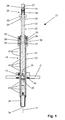
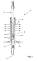
- Die Erfindung wird nachstehend anhand von zwei Ausführungsbeispielen näher erläutert. Es zeigen:
- Fig. 1
- Ein erstes Ausführungsbeispiel eines Setzwerkzeugs im Längsschnitt;
- Fig. 2 A-C
- der Setzvorgang mit dem erfindungsgemässen Setzwerkzeugs in drei Montagezuständen; und
- Fig. 3
- ein zweites Ausführungsbeispiel eines Setzwerkzeugs im Längsschnitt.
- Grundsätzlich sind in den Figuren gleiche Teile mit den gleichen Bezugszeichen versehen.
- Das in den
Figuren 1 und2 A-C dargestellte Setzwerkzeug 21 für einen mit einer Spreizschraube als Befestigungsmittel 16 im Untergrund 6 verankerbaren Dämmstoffdübel 11 weist eine erste Antriebswelle 22 und eine zweite Antriebswelle 32 auf. - Die erste Antriebswelle 22 weist einen sich entlang einer Längsachse 31 erstreckenden Schaft 23 mit einer Schrauberbitaufnahme als erstes Drehmitnahmemittel 24 für das Befestigungsmittel 16 an einem ersten Ende 25 und mit einem Einsteckende als zweites Drehmitnahmemittel 26 für einen Elektroschrauber als Setzwerkzeuggerät 8 an einem zweiten, dem ersten Ende 25 gegenüberliegenden Ende 27 auf. Am zweiten Ende 27 ist eine zusätzliche Kupplung 28 vorgesehen.
- Die zusätzliche Kupplung 28 umfasst einen hülsenförmigen Abschnitt 51, der koaxial über das zweite Ende 25 der ersten Antriebswelle 22 geführt ist. An der ersten Antriebswelle 22 sind radial von der ersten Antriebswelle 22 abragende Mitnehmernocken 29 vorgesehen, welche mit Nockenaufnahmen 53 an dem hülsenförmigen Abschnitt 51 in Eingriff bringbar sind. Zwischen dem hülsenförmigen Abschnitt 51 und einem Bereich des zweiten Endes 25 ist ein Federelement 52 vorgesehen, z. B. eine Spiralfeder, welches die zusätzliche Kupplung 28 in einer ausgekuppelten Stellung hält.
- Die zweite Antriebswelle 32 ist koaxial zur ersten Antriebswelle 22 angeordnet und weist einen hohlen Schaft 33 mit einem Aussenvielkant als drittes Drehmitnahmemittel 34 für den Dämmstoffdübel 11 an einem ersten Ende 35 auf. An einem Bereich beabstandet zu dem ersten Ende 35 der zweiten Antriebswelle 32, der in diesem Ausführungsbeispiel dem zweiten Ende 37 der zweiten Antriebswelle 32 entspricht, ist eine durch axialen Druck lösbare Kupplung 38 zur Übertragung eines Drehmomentes von der ersten Antriebswelle 22 auf die zweite Antriebswelle 32 vorgesehen.
- Die Kupplung 38 umfasst einen Klemmring 56, der eine Steuerkurve für Sperrelemente 57 in Form von Kugeln aufweist. Die Sperrelemente 57 greifen in eine Steuerkurve an der ersten Antriebswelle 22 ein. Die Kupplung 38 ist von einem Gehäuse 58 umgeben, welches die radiale Projektion der zweiten Antriebswelle 32 überragt. In dem Gehäuse 58 ist weiter ein Federelement 59 vorgesehen, z. B. eine Spiralfeder, welches den Klemmring 56 in Kontakt mit den Sperrelementen 57 zwingt und somit die Kupplung 38 in einem eingekuppelten Zustand hält.
- Weiter ist an der zweiten Antriebswelle 32 über ein Drehlager ein Anschlagteller 41 frei drehbar gelagert. Dessen axiale Distanz zum ersten Ende 35 der zweiten Antriebswelle 32 ist über eine Positioniereinrichtung 46 voreinstellbar. Der Anschlagteller 41 ist zu dessen Positionierung an der zweiten Antriebswelle 32 bezogen auf die Längsachse 31 axial verschieblich angeordnet. Die Positioniereinrichtung 46 umfasst mehrere radial angeordnete und radial umlaufende Rastnuten 47 sowie eine in die Rastnuten 47 eingreifbare Halteeinrichtung 43, mittels welcher der Anschlagteller 41 an der zweiten Antriebswelle 32 axial fixierbar ist. Zwischen dem Anschlagteller 41 und der Halteeinrichtung 43 ist ein Drehlager 42 vorgesehen.
- Nachfolgend wird anhand der
Figuren 2 A-C der Setzvorgang eines Dämmstoffdübels 11 mit dem erfindungsgemässen Setzwerkzeug 21 dargelegt. - Der Dämmstoffdübel 11 ist mit der Spreizschraube als Befestigungsmittel 16 versehen und wird als Ganzes auf das Setzwerkzeug 21 aufgesetzt sowie anschliessend in das zuvor durch die zu befestigende Dämmstoffplatte 7 hindurch in den Untergrund 6 erstellte Bohrloch 9 eingeschoben (siehe
Fig. 2A ). Alternativ wird zuerst der Dämmstoffdübel 11 mit der Spreizschraube in das Bohrloch 9 eingeführt und dann das Setzwerkzeug 21 mit dem Dämmstoffdübel 11 gekoppelt. Der Dämmstoffdübel 11 weist an einem Ende einen wendelartiger Druckteller 12 mit einer Aufnahme als Drehmitnahme 13 auf, welche mit dem dritten Drehmitnahmemittel 34 am ersten Ende 35 der zweiten Antriebswelle 32 zur Übertragung des Drehmomentes von der zweiten Antriebswelle 32 auf den Dämmstoffdübel 11 in Eingriff bringbar ist. Zuvor wurde der Anschlagteller 41 zur Einstellung der gewünschten Setztiefe des Dämmstoffdübels 11 axial entlang der zweiten Antriebswelle 32 verschoben und mittels der Positioniereinrichtung 46 an der zweiten Antriebswelle 32 axial fixiert. - Durch Druck in Setzrichtung S des Dämmstoffdübels 11 wird die am zweiten Ende 27 der ersten Antriebswelle 22 angeordnete zusätzliche Kupplung 28 eingekuppelt, so dass das von dem Setzwerkzeuggerät 8 erzeugte Drehmoment auf die erste Antriebswelle 22 und von dieser über die Kupplung 38 auf die zweite Antriebswelle 32 übertragen wird.
- Sobald die gewünschte Setztiefe des Dämmstoffdübels 11 erreicht ist (siehe
Fig. 2B ), liegt der Anschlagteller 41 an der Oberfläche 10 der Dämmstoffplatte 7 an. Bei einem weiteren Vorschub des Setzwerkzeugs 21 in Setzrichtung S erhöht sich der Druck auf die Kupplung 38 zwischen der zweiten Antriebswelle 32 und der ersten Antriebswelle 22, so dass diese auslöst und eine Übertragung des Drehmomentes von der ersten Antriebswelle 22 auf die zweite Antriebswelle 32 und somit auf den Dämmstoffdübel 11 unterbricht. Die erste Antriebswelle 22 wird weiterhin rotatorisch angetrieben, so dass das Befestigungsmittel 16 weiter zum Aufweiten des Verankerungsbereichs 14 des Dämmstoffdübels 11 eintreibbar ist. - Das dritte Drehmitnahmemittel 34 an der zweiten Antriebswelle 32 besitzt vorteilhaft eine konische Ausbildung, so dass beim Setzen des Dämmstoffdübels 11 ein Reibschluss beziehungsweise eine Klemmung zwischen dem dritten Drehmitnahmemittel 34 und der Drehmitnahme 13 des Dämmstoffdübels 11 erfolgt. Durch die leicht lösbare Haltekraft zwischen dem Setzwerkzeug 21 und dem Dämmstoffdübel 11 wird die zweite Antriebswelle 32 automatisch in die vordere, eingekuppelte Ausgangsstellung gebracht, wenn das Setzwerkzeug 21 nach Beendigung des Setzvorgangs herausgezogen wird (siehe
Fig. 2C ). Stellt sich bei einem Setzvorgang ausnahmsweise kein Klemmen zwischen dem Setzwerkzeug 21 und des Dämmstoffdübels 11 ein, so kann die zweite Antriebswelle 32 manuell wieder nach vorne in Richtung des ersten Endes 25 der ersten Antriebswelle 22 geschoben werden, bis die Kupplung 38 die erste Antriebswelle 22 und die zweite Antriebswelle 32 wieder drehfest miteinander kuppelt. Nun steht das Setzwerkzeug 21 für einen erneuten Setzvorgang eines weiteren Dämmstoffdübels 11 zur Verfügung, wobei dieser exakt und korrekt tief wie der zuvor gesetzte Dämmstoffdübel 11 gesetzt wird. - Das in der
Figur 3 dargestellte Setzwerkzeug 61 entspricht im Wesentlichen dem Setzwerkzeug 21 und unterscheidet sich von diesem lediglich durch die Ausgestaltung der Positioniereinrichtung 86. Die Positioniereinrichtung 86 umfasst mehrere Distanzelemente 87 und 88, die zwischen dem Anschlagteller 81 und einem Anschlag 83 an der zweiten Antriebswelle 72 axial hintereinander angeordnet sind. Der Anschlag 83 ist an einem Endbereich an einem zweiten, dem ersten Ende 75 gegenüberliegenden Ende 77 der zweiten Antriebswelle 72 ausgebildet und wird von einem die radiale Projektion der zweiten Antriebswelle 72 überragenden Gehäuseabschnitt der Kupplung 78 zwischen der ersten Antriebswelle 62 und der zweiten Antriebswelle 72 gebildet. - Das Distanzelement 87 ist mit dem Anschlagteller 81 fest verbunden und weist für eine Anpassung der axialen Länge radial umlaufende Solltrennstellen 89 auf, entlang derer das Distanzelement 87 einfach ablängbar ist. Die Distanzelemente 88 sind im Wesentlichen hohlzylindrisch ausgebildet und weisen jeweils einen sich über deren gesamte axiale Länge des Distanzelements 88 ersteckenden Längsschlitz 90 auf, so dass diese bei Bedarf einfach auf die zweite Antriebswelle 72 aufsteckbar sind. Vorteilhaft sind diese aus einem radial elastischen Material gefertigt, was ein einfaches Aufclipsen zur Montage der Distanzelemente 88 an der zweiten Antriebswelle 72 ermöglicht.
Claims (10)
- Setzwerkzeug (21; 61) für einen mit einem Befestigungsmittel (16) im Untergrund (6) verankerbaren Dämmstoffdübel (11), miteiner ersten Antriebswelle (22; 62), die einen sich entlang einer Längsachse (31) erstreckenden Schaft (23) mit einem ersten Drehmitnahmemittel (24) für das Befestigungsmittel (16) an einem ersten Ende (25) und mit einem zweiten Drehmitnahmemittel (26) für ein Setzwerkzeuggerät (8) an einem zweiten, dem ersten Ende (25) gegenüberliegenden Ende (27) aufweist, und miteiner koaxial zur ersten Antriebswelle (22; 62) angeordneten zweiten Antriebswelle (32; 72), die einen hohlen Schaft (33) mit einem dritten Drehmitnahmemittel (34) für den Dämmstoffdübel (11) an einem ersten Ende (35; 75) aufweist, sowiemit einer durch axialen Druck lösbaren Kupplung (38; 78) zur Übertragung eines Drehmomentes von der ersten Antriebswelle (22; 62) auf die zweite Antriebswelle (32; 72), die an einem Bereich beabstandet zu dem ersten Ende (25; 75) der zweiten Antriebswelle (32; 72) angeordnet ist, dadurch gekennzeichnet, dassan der zweiten Antriebswelle (32; 72) ein Anschlagteller (41; 81) gelagert ist, dessen axiale Distanz zum ersten Ende (35; 75) der zweiten Antriebswelle (32; 72) über eine Positioniereinrichtung (46; 86) voreinstellbar ist.
- Setzwerkzeug nach Anspruch 1, dadurch gekennzeichnet, dass der Anschlagteller (41; 81) über ein Drehlager an der zweiten Antriebswelle (32; 72) gelagert ist.
- Setzwerkzeug nach Anspruch 1 oder 2, dadurch gekennzeichnet, dass die Positioniereinrichtung (46) mehrere radial angeordnete Rastnuten (47) und eine in die Rastnuten (47) eingreifbare Halteeinrichtung (43) umfasst, über die der Anschlagteller (41) an der zweiten Antriebswelle (32) axial fixierbar ist.
- Setzwerkzeug nach Anspruch 3, dadurch gekennzeichnet, dass die Rastnuten (47) radial umlaufend ausgebildet sind.
- Setzwerkzeug nach Anspruch 3 oder 4, dadurch gekennzeichnet, dass zwischen dem Anschlagteller (41) und der Halteeinrichtung (43) ein Drehlager (42) vorgesehen ist.
- Setzwerkzeug nach Anspruch 1 oder 2, dadurch gekennzeichnet, dass die Positioniereinrichtung (86) zumindest ein Distanzelement (87, 88) umfasst, das zwischen dem Anschlagteller (81) und einem Anschlag (83) an der zweiten Antriebswelle (72) angeordnet ist.
- Setzwerkzeug nach Anspruch 6, dadurch gekennzeichnet, dass der Anschlag (83) an einem Endbereich an einem zweiten, dem ersten Ende (75) gegenüberliegenden Ende (77) der zweiten Antriebswelle (72) ausgebildet ist.
- Setzwerkzeug nach Anspruch 6 oder 7, dadurch gekennzeichnet, dass das zumindest eine Distanzelement (87) Solltrennstellen (89) aufweist.
- Setzwerkzeug nach einem der Ansprüche 6 bis 8, dadurch gekennzeichnet, dass die Positioniereinrichtung (86) mehrere Distanzelemente (88) umfasst, die axial hintereinander bedarfsweise anordnenbar sind.
- Setzwerkzeug nach einem der Ansprüche 6 bis 9, dadurch gekennzeichnet, dass das zumindest eine Distanzelement (88) im Wesentlichen hohlzylindrisch ausgebildet ist und einen sich über die gesamte axiale Länge des Distanzelementes (88) ersteckenden Längsschlitz (90) aufweist.
Applications Claiming Priority (1)
| Application Number | Priority Date | Filing Date | Title |
|---|---|---|---|
| DE102007000235A DE102007000235A1 (de) | 2007-04-20 | 2007-04-20 | Setzwerkzeug für einen Dämmstoffdübel |
Publications (3)
| Publication Number | Publication Date |
|---|---|
| EP1982797A2 true EP1982797A2 (de) | 2008-10-22 |
| EP1982797A3 EP1982797A3 (de) | 2010-04-28 |
| EP1982797B1 EP1982797B1 (de) | 2012-01-25 |
Family
ID=39580324
Family Applications (1)
| Application Number | Title | Priority Date | Filing Date |
|---|---|---|---|
| EP08103475A Active EP1982797B1 (de) | 2007-04-20 | 2008-04-10 | Setzwerkzeug für einen Dämmstoffdübel |
Country Status (3)
| Country | Link |
|---|---|
| EP (1) | EP1982797B1 (de) |
| AT (1) | ATE542638T1 (de) |
| DE (1) | DE102007000235A1 (de) |
Cited By (9)
| Publication number | Priority date | Publication date | Assignee | Title |
|---|---|---|---|---|
| AT510315A1 (de) * | 2010-08-27 | 2012-03-15 | Froewis Markus | Anordnung zur, insbesondere distanzierten, befestigung zumindest einer dämmstoffplatte an einem gebäude |
| WO2012049114A1 (de) * | 2010-10-14 | 2012-04-19 | Sfs Intec Holding Ag | Werkzeug zur montage von dämmstoffhaltern |
| EP2775066A1 (de) * | 2013-03-05 | 2014-09-10 | EJOT Baubefestigungen GmbH | Schwenkbare Anschlagscheibe |
| EP2689894A3 (de) * | 2012-07-25 | 2017-12-27 | fischerwerke GmbH & Co. KG | Werkzeug für die Montage eines Dämmstoffdübels |
| EP2191938A3 (de) * | 2008-11-27 | 2017-12-27 | HILTI Aktiengesellschaft | Setzwerkzeug für einen Dämmstoffdübel |
| EP3536459A1 (de) * | 2018-03-07 | 2019-09-11 | EJOT Baubefestigungen GmbH | Montagevorrichtung |
| US11008751B2 (en) * | 2016-06-16 | 2021-05-18 | Ejot Baubefestigungen Gmbh | System for fastening attachments to a substrate with an insulation layer |
| CN115592601A (zh) * | 2021-06-28 | 2023-01-13 | 中国航发商用航空发动机有限责任公司(Cn) | 核心机单元安装工具及其使用方法 |
| US12472614B2 (en) | 2021-06-14 | 2025-11-18 | Milwaukee Electric Tool Corporation | Power tool for installing drop-in anchors |
Families Citing this family (4)
| Publication number | Priority date | Publication date | Assignee | Title |
|---|---|---|---|---|
| DE102009034407A1 (de) | 2009-07-23 | 2011-02-03 | Fuchs Technology Holding Ag | Elektrodentragarm mit lokal befestigtem Stromleiter |
| EP2639374B1 (de) | 2012-03-16 | 2018-06-13 | EJOT Baubefestigungen GmbH | Befestigung von Dämmplatten |
| EP3323556A1 (de) | 2016-11-17 | 2018-05-23 | HILTI Aktiengesellschaft | Setzgerät mit axial sperrbaren antriebswellen, setzverfahren und spreizanker hierfür |
| DE102017217147A1 (de) * | 2017-09-27 | 2019-03-28 | Van Roij Fasteners Europe Bv | Distanzbefestiger |
Citations (2)
| Publication number | Priority date | Publication date | Assignee | Title |
|---|---|---|---|---|
| US5255485A (en) | 1988-08-25 | 1993-10-26 | Stuart H. Lemke | Apparatus and method for installing roofing fasteners |
| DE19754356A1 (de) | 1997-12-08 | 1999-06-10 | Fischer Artur Werke Gmbh | Werkzeug zur Montage von Dämmstoffhaltern zur Dachbahnbefestigung |
Family Cites Families (2)
| Publication number | Priority date | Publication date | Assignee | Title |
|---|---|---|---|---|
| US6308483B1 (en) * | 2000-07-07 | 2001-10-30 | Robert L. Romine | Roofing fastener assembly |
| AU2002235860A1 (en) * | 2001-01-22 | 2002-07-30 | Sfs Intec Holding Ag | Device for screwing in fastening elements |
-
2007
- 2007-04-20 DE DE102007000235A patent/DE102007000235A1/de not_active Withdrawn
-
2008
- 2008-04-10 AT AT08103475T patent/ATE542638T1/de active
- 2008-04-10 EP EP08103475A patent/EP1982797B1/de active Active
Patent Citations (2)
| Publication number | Priority date | Publication date | Assignee | Title |
|---|---|---|---|---|
| US5255485A (en) | 1988-08-25 | 1993-10-26 | Stuart H. Lemke | Apparatus and method for installing roofing fasteners |
| DE19754356A1 (de) | 1997-12-08 | 1999-06-10 | Fischer Artur Werke Gmbh | Werkzeug zur Montage von Dämmstoffhaltern zur Dachbahnbefestigung |
Cited By (12)
| Publication number | Priority date | Publication date | Assignee | Title |
|---|---|---|---|---|
| EP2191938A3 (de) * | 2008-11-27 | 2017-12-27 | HILTI Aktiengesellschaft | Setzwerkzeug für einen Dämmstoffdübel |
| AT510315A1 (de) * | 2010-08-27 | 2012-03-15 | Froewis Markus | Anordnung zur, insbesondere distanzierten, befestigung zumindest einer dämmstoffplatte an einem gebäude |
| AT510315B1 (de) * | 2010-08-27 | 2013-09-15 | Froewis Markus | Anordnung zur, insbesondere distanzierten, befestigung zumindest einer dämmstoffplatte an einem gebäude |
| WO2012049114A1 (de) * | 2010-10-14 | 2012-04-19 | Sfs Intec Holding Ag | Werkzeug zur montage von dämmstoffhaltern |
| EA028901B1 (ru) * | 2010-10-14 | 2018-01-31 | Сфс Интек Холдинг Аг | Инструмент для монтажа держателей изоляционного материала |
| EP2689894A3 (de) * | 2012-07-25 | 2017-12-27 | fischerwerke GmbH & Co. KG | Werkzeug für die Montage eines Dämmstoffdübels |
| EP2775066A1 (de) * | 2013-03-05 | 2014-09-10 | EJOT Baubefestigungen GmbH | Schwenkbare Anschlagscheibe |
| US11008751B2 (en) * | 2016-06-16 | 2021-05-18 | Ejot Baubefestigungen Gmbh | System for fastening attachments to a substrate with an insulation layer |
| EP3536459A1 (de) * | 2018-03-07 | 2019-09-11 | EJOT Baubefestigungen GmbH | Montagevorrichtung |
| US12472614B2 (en) | 2021-06-14 | 2025-11-18 | Milwaukee Electric Tool Corporation | Power tool for installing drop-in anchors |
| CN115592601A (zh) * | 2021-06-28 | 2023-01-13 | 中国航发商用航空发动机有限责任公司(Cn) | 核心机单元安装工具及其使用方法 |
| CN115592601B (zh) * | 2021-06-28 | 2025-07-15 | 中国航发商用航空发动机有限责任公司 | 核心机单元安装工具及其使用方法 |
Also Published As
| Publication number | Publication date |
|---|---|
| ATE542638T1 (de) | 2012-02-15 |
| EP1982797B1 (de) | 2012-01-25 |
| EP1982797A3 (de) | 2010-04-28 |
| DE102007000235A1 (de) | 2008-10-23 |
Similar Documents
| Publication | Publication Date | Title |
|---|---|---|
| EP1982797B1 (de) | Setzwerkzeug für einen Dämmstoffdübel | |
| EP2191938B1 (de) | Setzwerkzeug für einen Dämmstoffdübel | |
| EP2218924B1 (de) | Befestigungsvorrichtung zur Anordnung an einer Montageschiene | |
| DE102004006205B3 (de) | Bohradapter | |
| EP0528262B1 (de) | Mechanische Spannvorrichtung | |
| WO1998042480A1 (de) | Schrauberelement | |
| EP2466025A2 (de) | Dämmstoffhalter | |
| WO1998047649A1 (de) | Spannfutter für rundlaufwerkzeuge | |
| EP1262266B1 (de) | Spannvorrichtung | |
| EP2905392B1 (de) | Setzverfahren zur befestigung von dämmstoffen | |
| EP1260319B1 (de) | Schraubvorrichtung für Schraubendreher-Einsätze | |
| EP3755503B1 (de) | Setzwerkzeug und setzverfahren für bolzenanker | |
| EP0808696A1 (de) | Befestigungssystem und Verfahren zur Erstellung von Befestigungen | |
| EP0394604A2 (de) | Verfahren und Vorrichtung zum Formen eines Gewindes in Gestein oder Beton | |
| DE102013103287A1 (de) | Dämmstoffhalter | |
| EP2905391B1 (de) | Kombination eines Dübels und eines Setzwerkzeugs bzw. Verfahren zur Befestigung von Dämmstoffen | |
| WO2007115688A9 (de) | Einrichtung zum eindrehen von schrauben | |
| DE102012106745B4 (de) | Werkzeug für die Montage eines Dämmstoffdübels | |
| EP2786840A2 (de) | Setzgerät und dessen Kombination mit einem Befestigungselement | |
| DE102011006718A1 (de) | Hilfsvorrichtung und Verfahren zur Positionierung und Führung einer Bohrschraube | |
| DE102013103429A1 (de) | Dämmstoffhalter | |
| DE102007005280A1 (de) | Spreizdübel | |
| DE102025129725A1 (de) | Dübeldemontagewerkzeug und Verfahren zum Entfernen eines Dübels mit dem Dübeldemontagewerkzeug | |
| AT229246B (de) | Werkzeug zum Aufbringen eines drahtwendelförmigen Gewindemantels auf einen mit einem Außengewinde versehenen Schaft | |
| EP4563103A1 (de) | Zentriereinheit mit verriegelungsschraube |
Legal Events
| Date | Code | Title | Description |
|---|---|---|---|
| PUAI | Public reference made under article 153(3) epc to a published international application that has entered the european phase |
Free format text: ORIGINAL CODE: 0009012 |
|
| AK | Designated contracting states |
Kind code of ref document: A2 Designated state(s): AT BE BG CH CY CZ DE DK EE ES FI FR GB GR HR HU IE IS IT LI LT LU LV MC MT NL NO PL PT RO SE SI SK TR |
|
| AX | Request for extension of the european patent |
Extension state: AL BA MK RS |
|
| PUAL | Search report despatched |
Free format text: ORIGINAL CODE: 0009013 |
|
| AK | Designated contracting states |
Kind code of ref document: A3 Designated state(s): AT BE BG CH CY CZ DE DK EE ES FI FR GB GR HR HU IE IS IT LI LT LU LV MC MT NL NO PL PT RO SE SI SK TR |
|
| AX | Request for extension of the european patent |
Extension state: AL BA MK RS |
|
| 17P | Request for examination filed |
Effective date: 20101028 |
|
| AKX | Designation fees paid |
Designated state(s): AT BE BG CH CY CZ DE DK EE ES FI FR GB GR HR HU IE IS IT LI LT LU LV MC MT NL NO PL PT RO SE SI SK TR |
|
| GRAP | Despatch of communication of intention to grant a patent |
Free format text: ORIGINAL CODE: EPIDOSNIGR1 |
|
| GRAS | Grant fee paid |
Free format text: ORIGINAL CODE: EPIDOSNIGR3 |
|
| GRAA | (expected) grant |
Free format text: ORIGINAL CODE: 0009210 |
|
| AK | Designated contracting states |
Kind code of ref document: B1 Designated state(s): AT BE BG CH CY CZ DE DK EE ES FI FR GB GR HR HU IE IS IT LI LT LU LV MC MT NL NO PL PT RO SE SI SK TR |
|
| REG | Reference to a national code |
Ref country code: GB Ref legal event code: FG4D Free format text: NOT ENGLISH |
|
| REG | Reference to a national code |
Ref country code: CH Ref legal event code: EP |
|
| REG | Reference to a national code |
Ref country code: AT Ref legal event code: REF Ref document number: 542638 Country of ref document: AT Kind code of ref document: T Effective date: 20120215 |
|
| REG | Reference to a national code |
Ref country code: IE Ref legal event code: FG4D |
|
| REG | Reference to a national code |
Ref country code: DE Ref legal event code: R096 Ref document number: 502008006173 Country of ref document: DE Effective date: 20120322 |
|
| REG | Reference to a national code |
Ref country code: NL Ref legal event code: VDEP Effective date: 20120125 |
|
| LTIE | Lt: invalidation of european patent or patent extension |
Effective date: 20120125 |
|
| REG | Reference to a national code |
Ref country code: SK Ref legal event code: T3 Ref document number: E 11536 Country of ref document: SK |
|
| PG25 | Lapsed in a contracting state [announced via postgrant information from national office to epo] |
Ref country code: NO Free format text: LAPSE BECAUSE OF FAILURE TO SUBMIT A TRANSLATION OF THE DESCRIPTION OR TO PAY THE FEE WITHIN THE PRESCRIBED TIME-LIMIT Effective date: 20120425 Ref country code: LT Free format text: LAPSE BECAUSE OF FAILURE TO SUBMIT A TRANSLATION OF THE DESCRIPTION OR TO PAY THE FEE WITHIN THE PRESCRIBED TIME-LIMIT Effective date: 20120125 Ref country code: HR Free format text: LAPSE BECAUSE OF FAILURE TO SUBMIT A TRANSLATION OF THE DESCRIPTION OR TO PAY THE FEE WITHIN THE PRESCRIBED TIME-LIMIT Effective date: 20120125 Ref country code: IS Free format text: LAPSE BECAUSE OF FAILURE TO SUBMIT A TRANSLATION OF THE DESCRIPTION OR TO PAY THE FEE WITHIN THE PRESCRIBED TIME-LIMIT Effective date: 20120525 Ref country code: BG Free format text: LAPSE BECAUSE OF FAILURE TO SUBMIT A TRANSLATION OF THE DESCRIPTION OR TO PAY THE FEE WITHIN THE PRESCRIBED TIME-LIMIT Effective date: 20120425 Ref country code: NL Free format text: LAPSE BECAUSE OF FAILURE TO SUBMIT A TRANSLATION OF THE DESCRIPTION OR TO PAY THE FEE WITHIN THE PRESCRIBED TIME-LIMIT Effective date: 20120125 |
|
| PG25 | Lapsed in a contracting state [announced via postgrant information from national office to epo] |
Ref country code: PT Free format text: LAPSE BECAUSE OF FAILURE TO SUBMIT A TRANSLATION OF THE DESCRIPTION OR TO PAY THE FEE WITHIN THE PRESCRIBED TIME-LIMIT Effective date: 20120525 Ref country code: GR Free format text: LAPSE BECAUSE OF FAILURE TO SUBMIT A TRANSLATION OF THE DESCRIPTION OR TO PAY THE FEE WITHIN THE PRESCRIBED TIME-LIMIT Effective date: 20120426 Ref country code: PL Free format text: LAPSE BECAUSE OF FAILURE TO SUBMIT A TRANSLATION OF THE DESCRIPTION OR TO PAY THE FEE WITHIN THE PRESCRIBED TIME-LIMIT Effective date: 20120125 Ref country code: LV Free format text: LAPSE BECAUSE OF FAILURE TO SUBMIT A TRANSLATION OF THE DESCRIPTION OR TO PAY THE FEE WITHIN THE PRESCRIBED TIME-LIMIT Effective date: 20120125 Ref country code: FI Free format text: LAPSE BECAUSE OF FAILURE TO SUBMIT A TRANSLATION OF THE DESCRIPTION OR TO PAY THE FEE WITHIN THE PRESCRIBED TIME-LIMIT Effective date: 20120125 |
|
| PG25 | Lapsed in a contracting state [announced via postgrant information from national office to epo] |
Ref country code: CY Free format text: LAPSE BECAUSE OF FAILURE TO SUBMIT A TRANSLATION OF THE DESCRIPTION OR TO PAY THE FEE WITHIN THE PRESCRIBED TIME-LIMIT Effective date: 20120125 |
|
| BERE | Be: lapsed |
Owner name: HILTI AKTIENGESELLSCHAFT Effective date: 20120430 |
|
| PG25 | Lapsed in a contracting state [announced via postgrant information from national office to epo] |
Ref country code: EE Free format text: LAPSE BECAUSE OF FAILURE TO SUBMIT A TRANSLATION OF THE DESCRIPTION OR TO PAY THE FEE WITHIN THE PRESCRIBED TIME-LIMIT Effective date: 20120125 Ref country code: RO Free format text: LAPSE BECAUSE OF FAILURE TO SUBMIT A TRANSLATION OF THE DESCRIPTION OR TO PAY THE FEE WITHIN THE PRESCRIBED TIME-LIMIT Effective date: 20120125 Ref country code: SE Free format text: LAPSE BECAUSE OF FAILURE TO SUBMIT A TRANSLATION OF THE DESCRIPTION OR TO PAY THE FEE WITHIN THE PRESCRIBED TIME-LIMIT Effective date: 20120125 Ref country code: SI Free format text: LAPSE BECAUSE OF FAILURE TO SUBMIT A TRANSLATION OF THE DESCRIPTION OR TO PAY THE FEE WITHIN THE PRESCRIBED TIME-LIMIT Effective date: 20120125 Ref country code: DK Free format text: LAPSE BECAUSE OF FAILURE TO SUBMIT A TRANSLATION OF THE DESCRIPTION OR TO PAY THE FEE WITHIN THE PRESCRIBED TIME-LIMIT Effective date: 20120125 |
|
| PG25 | Lapsed in a contracting state [announced via postgrant information from national office to epo] |
Ref country code: IT Free format text: LAPSE BECAUSE OF FAILURE TO SUBMIT A TRANSLATION OF THE DESCRIPTION OR TO PAY THE FEE WITHIN THE PRESCRIBED TIME-LIMIT Effective date: 20120125 Ref country code: MC Free format text: LAPSE BECAUSE OF NON-PAYMENT OF DUE FEES Effective date: 20120430 |
|
| PLBE | No opposition filed within time limit |
Free format text: ORIGINAL CODE: 0009261 |
|
| STAA | Information on the status of an ep patent application or granted ep patent |
Free format text: STATUS: NO OPPOSITION FILED WITHIN TIME LIMIT |
|
| GBPC | Gb: european patent ceased through non-payment of renewal fee |
Effective date: 20120425 |
|
| 26N | No opposition filed |
Effective date: 20121026 |
|
| PG25 | Lapsed in a contracting state [announced via postgrant information from national office to epo] |
Ref country code: BE Free format text: LAPSE BECAUSE OF NON-PAYMENT OF DUE FEES Effective date: 20120430 Ref country code: GB Free format text: LAPSE BECAUSE OF NON-PAYMENT OF DUE FEES Effective date: 20120425 |
|
| REG | Reference to a national code |
Ref country code: DE Ref legal event code: R097 Ref document number: 502008006173 Country of ref document: DE Effective date: 20121026 |
|
| PG25 | Lapsed in a contracting state [announced via postgrant information from national office to epo] |
Ref country code: ES Free format text: LAPSE BECAUSE OF FAILURE TO SUBMIT A TRANSLATION OF THE DESCRIPTION OR TO PAY THE FEE WITHIN THE PRESCRIBED TIME-LIMIT Effective date: 20120506 |
|
| PG25 | Lapsed in a contracting state [announced via postgrant information from national office to epo] |
Ref country code: MT Free format text: LAPSE BECAUSE OF FAILURE TO SUBMIT A TRANSLATION OF THE DESCRIPTION OR TO PAY THE FEE WITHIN THE PRESCRIBED TIME-LIMIT Effective date: 20120125 |
|
| PG25 | Lapsed in a contracting state [announced via postgrant information from national office to epo] |
Ref country code: TR Free format text: LAPSE BECAUSE OF FAILURE TO SUBMIT A TRANSLATION OF THE DESCRIPTION OR TO PAY THE FEE WITHIN THE PRESCRIBED TIME-LIMIT Effective date: 20120125 |
|
| PG25 | Lapsed in a contracting state [announced via postgrant information from national office to epo] |
Ref country code: LU Free format text: LAPSE BECAUSE OF NON-PAYMENT OF DUE FEES Effective date: 20120410 |
|
| PG25 | Lapsed in a contracting state [announced via postgrant information from national office to epo] |
Ref country code: HU Free format text: LAPSE BECAUSE OF FAILURE TO SUBMIT A TRANSLATION OF THE DESCRIPTION OR TO PAY THE FEE WITHIN THE PRESCRIBED TIME-LIMIT Effective date: 20080410 |
|
| REG | Reference to a national code |
Ref country code: FR Ref legal event code: PLFP Year of fee payment: 9 |
|
| REG | Reference to a national code |
Ref country code: FR Ref legal event code: PLFP Year of fee payment: 10 |
|
| REG | Reference to a national code |
Ref country code: FR Ref legal event code: PLFP Year of fee payment: 11 |
|
| PGFP | Annual fee paid to national office [announced via postgrant information from national office to epo] |
Ref country code: IE Payment date: 20230419 Year of fee payment: 16 |
|
| PGFP | Annual fee paid to national office [announced via postgrant information from national office to epo] |
Ref country code: AT Payment date: 20230420 Year of fee payment: 16 |
|
| PGFP | Annual fee paid to national office [announced via postgrant information from national office to epo] |
Ref country code: CZ Payment date: 20240402 Year of fee payment: 17 |
|
| PGFP | Annual fee paid to national office [announced via postgrant information from national office to epo] |
Ref country code: SK Payment date: 20240403 Year of fee payment: 17 |
|
| REG | Reference to a national code |
Ref country code: AT Ref legal event code: MM01 Ref document number: 542638 Country of ref document: AT Kind code of ref document: T Effective date: 20240410 |
|
| PG25 | Lapsed in a contracting state [announced via postgrant information from national office to epo] |
Ref country code: AT Free format text: LAPSE BECAUSE OF NON-PAYMENT OF DUE FEES Effective date: 20240410 |
|
| PG25 | Lapsed in a contracting state [announced via postgrant information from national office to epo] |
Ref country code: AT Free format text: LAPSE BECAUSE OF NON-PAYMENT OF DUE FEES Effective date: 20240410 |
|
| PG25 | Lapsed in a contracting state [announced via postgrant information from national office to epo] |
Ref country code: IE Free format text: LAPSE BECAUSE OF NON-PAYMENT OF DUE FEES Effective date: 20240410 |
|
| PGFP | Annual fee paid to national office [announced via postgrant information from national office to epo] |
Ref country code: DE Payment date: 20250422 Year of fee payment: 18 |
|
| PGFP | Annual fee paid to national office [announced via postgrant information from national office to epo] |
Ref country code: FR Payment date: 20250424 Year of fee payment: 18 |
|
| PGFP | Annual fee paid to national office [announced via postgrant information from national office to epo] |
Ref country code: CH Payment date: 20250501 Year of fee payment: 18 |
|
| PG25 | Lapsed in a contracting state [announced via postgrant information from national office to epo] |
Ref country code: CZ Free format text: LAPSE BECAUSE OF NON-PAYMENT OF DUE FEES Effective date: 20250410 |
|
| REG | Reference to a national code |
Ref country code: SK Ref legal event code: MM4A Ref document number: E 11536 Country of ref document: SK Effective date: 20250410 |
|
| PG25 | Lapsed in a contracting state [announced via postgrant information from national office to epo] |
Ref country code: SK Free format text: LAPSE BECAUSE OF NON-PAYMENT OF DUE FEES Effective date: 20250410 |
|
| REG | Reference to a national code |
Ref country code: CH Ref legal event code: U11 Free format text: ST27 STATUS EVENT CODE: U-0-0-U10-U11 (AS PROVIDED BY THE NATIONAL OFFICE) Effective date: 20260501 |